EP3378755A1 - Floatation device without pressurized container - Google Patents
Floatation device without pressurized container Download PDFInfo
- Publication number
- EP3378755A1 EP3378755A1 EP18163159.9A EP18163159A EP3378755A1 EP 3378755 A1 EP3378755 A1 EP 3378755A1 EP 18163159 A EP18163159 A EP 18163159A EP 3378755 A1 EP3378755 A1 EP 3378755A1
- Authority
- EP
- European Patent Office
- Prior art keywords
- floatation device
- valve
- pair
- assembly
- stiffener assembly
- Prior art date
- Legal status (The legal status is an assumption and is not a legal conclusion. Google has not performed a legal analysis and makes no representation as to the accuracy of the status listed.)
- Granted
Links
Images






Classifications
-
- B—PERFORMING OPERATIONS; TRANSPORTING
- B63—SHIPS OR OTHER WATERBORNE VESSELS; RELATED EQUIPMENT
- B63C—LAUNCHING, HAULING-OUT, OR DRY-DOCKING OF VESSELS; LIFE-SAVING IN WATER; EQUIPMENT FOR DWELLING OR WORKING UNDER WATER; MEANS FOR SALVAGING OR SEARCHING FOR UNDERWATER OBJECTS
- B63C9/00—Life-saving in water
- B63C9/08—Life-buoys, e.g. rings; Life-belts, jackets, suits, or the like
- B63C9/18—Inflatable equipment characterised by the gas-generating or inflation device
-
- B—PERFORMING OPERATIONS; TRANSPORTING
- B63—SHIPS OR OTHER WATERBORNE VESSELS; RELATED EQUIPMENT
- B63B—SHIPS OR OTHER WATERBORNE VESSELS; EQUIPMENT FOR SHIPPING
- B63B22/00—Buoys
- B63B22/22—Inflatable buoys with gas generating means
-
- B—PERFORMING OPERATIONS; TRANSPORTING
- B63—SHIPS OR OTHER WATERBORNE VESSELS; RELATED EQUIPMENT
- B63C—LAUNCHING, HAULING-OUT, OR DRY-DOCKING OF VESSELS; LIFE-SAVING IN WATER; EQUIPMENT FOR DWELLING OR WORKING UNDER WATER; MEANS FOR SALVAGING OR SEARCHING FOR UNDERWATER OBJECTS
- B63C9/00—Life-saving in water
- B63C9/08—Life-buoys, e.g. rings; Life-belts, jackets, suits, or the like
- B63C9/081—Life-buoys, e.g. rings; Life-belts, jackets, suits, or the like having compartments comprising elements which are filled with gas by deployment, e.g. sponge-like elements
-
- B—PERFORMING OPERATIONS; TRANSPORTING
- B63—SHIPS OR OTHER WATERBORNE VESSELS; RELATED EQUIPMENT
- B63C—LAUNCHING, HAULING-OUT, OR DRY-DOCKING OF VESSELS; LIFE-SAVING IN WATER; EQUIPMENT FOR DWELLING OR WORKING UNDER WATER; MEANS FOR SALVAGING OR SEARCHING FOR UNDERWATER OBJECTS
- B63C9/00—Life-saving in water
- B63C2009/0023—Particular features common to inflatable life-saving equipment
- B63C2009/0029—Inflation devices comprising automatic activation means, e.g. for puncturing gas-generating cartridges
- B63C2009/0035—Inflation devices comprising automatic activation means, e.g. for puncturing gas-generating cartridges activated by deployment of inflatable life-saving equipment
Definitions
- Exemplary embodiments pertain generally to emergency floatation devices adapted to assist in the rescue of persons from a body of water. More particularly, the disclosure related to emergency floatation devices that are configured to automatically inflate without the use of a pressurized cylinder.
- Throwable floatation devices are commonly used in rescue operations where a victim is drowning or stranded within a body of water. The floatation device is intended to safely support the victim until a more permanent rescue operation can be effectuated.
- a floatation device includes a body transformable between a retracted configuration and an extended configuration.
- a stiffener assembly is movable between a first position and a second position. The stiffener assembly is biased into the second position.
- the stiffener assembly is operably coupled to the body such that movement of the stiffener assembly between the first position and the second position causes the body to transform between the retracted position and the extended position.
- a partial vacuum is created within the body to inflate the floatation device.
- the mechanism is operable to inflate the body to a pressure substantially equal to an ambient atmospheric pressure.
- the stiffener assembly includes: a pair of first members operably coupled together by a pair of first structural connectors and a pair of second members operably coupled together by a pair of second structural connectors, each second member being disposed in overlapping arrangement with one of the pair of first members, the second members being rotatable relative to the first members.
- the pair of second structural connectors is at an angle relative to the first structural connectors.
- the pair of first structural connectors and the pair of second structural connectors are formed from a resilient material.
- the body includes a skin configured to define an interior cavity.
- the stiffener assembly is operably coupled to the skin.
- the floatation device further comprises a valve assembly arranged in fluid communication with the interior cavity, the valve assembly being coupled to the stiffener assembly.
- movement of the stiffener assembly to the second position causes at least one valve of the valve assembly to seal and block a flow into and out of the interior cavity.
- valve assembly comprises at least a first valve and a second valve operably coupled to one another, the first valve and the second valve being movable to selectively control a flow into and out of the interior cavity.
- a patch is mounted at at least one interface between the skin and the stiffener assembly.
- a method of inflating a floatation device includes biasing a stiffener assembly from a first position to a second position such that the floatation device transitions from a retracted position to an extended position, creating a partial vacuum within an interior cavity of the floatation device causing air to be drawn therein, and sealing at least one valve of a valve assembly of the floatation device to block a flow of air into and out of the interior cavity.
- manually inflating the floatation device includes equalizing a pressure within the interior cavity with an ambient atmospheric pressure.
- the floatation device 20 is configured to transform between a first, retracted configuration ( FIG. 2 ) and a second, extended configuration ( FIGS. 1 and 3 ).
- the floatation device 20 may be generally flattened and folded for storage, such as within a container for example.
- the floatation device 20 is generally filled with air or another gas to achieve a sufficient level of buoyancy required for an application.
- a stiffener assembly 22 is operable to automatically transform the floatation device 20 from the retracted configuration to the extended configuration.
- the stiffener assembly 22 includes a first stiffener 24 and a second stiffener 26 configured to cooperate with one another in a manner similar to a scissor mechanism to transition between a first configuration and a second configuration.
- the first stiffener 24 includes at least one first member 28.
- the stiffener assembly 22 includes a pair of substantially identical first members 28 arranged generally parallel and offset from one another and in vertical alignment. In such embodiments, the pair of first members 28 are rotated 180 degrees relative to one another such that a first surface of the first members 28 face towards one another.
- a pair of substantially identical first structural connectors 30 extend between and connect a first side of the pair of first members 28 and a second side of the pair of first members 28, respectively.
- the second stiffener 26 similarly includes at least one second member 32.
- the at least one second member 32 includes a pair of substantially identical second members 32 arranged parallel to and offset from one another in vertical alignment.
- the pair of second members 32 may additionally be rotated 180 degrees relative to one another.
- a pair of substantially identical second structural connectors 34 extends between and connects a first side of the pair of second members 32 and a second side of the pair of second members 32, respectively.
- the first structural connectors 30 of the first stiffener 24 and the second structural connectors 34 of the second stiffener 26 may, but need not be substantially identical to one another.
- the first and second structural connectors 30, 34 are formed from a thin, strong, and resilient material, such as steel for example.
- Each of the first members 28 includes a first arm 40 and a second arm 42 extending therefrom.
- each of the second members 32 has a first arm 44 and a second arm 46 extending therefrom.
- the at least one second member 32 is arranged in overlapping arrangement with the at least one first member 28.
- the second member 32 may have a contour complementary to and configured to receive a flange extending from the first member 28.
- the second structural connectors 34 are arranged at an angle to the first structural connectors 30.
- the angle formed between the second structural connectors 34 and the first structural connectors 30 is between about 60 degrees and about 120 degrees, such as about 90 degrees for example.
- a skin 50 is connected to the stiffener assembly 22. Accordingly, movement of the stiffener assembly 22 between the first configuration and the second configuration causes the floatation device 20 to transition between the retracted position and the extended position, respectively.
- the skin 50 is shaped to define an interior cavity capable of being filled with air when the float 20 is extended and releasing air to retract the float 20.
- the skin 50 may be formed from any suitable air tight material, such as is used in other known inflatable floatation devices for use in water safety rescue applications.
- the structural connectors 30, 34 of the stiffener assembly 22 are arranged about an exterior of the skin 50.
- the structural connectors 30, 34 may be coated with a protective coating to prevent the material of the skin 50 from being damaged or the structural connectors 30, 34 from corrosion due to exposure to moisture or high salt environments.
- patches 52 are used to provide reinforcement at the interface between the skin 50 and a corresponding structural connector 30, 34.
- the patches 52 may be adhered to the surface of the skin 50, or alternatively, may be mechanically fastened thereto.
- one or more handles or grips 54 is mounted to the exterior of the skin. The handle 54 is intended to allow a user to easy grasp and maneuver the floatation device when deployed.
- the length of the skin 50 extending between the structural connector 30, coupling the first arms 40 of the first members 28 and the structural connector 34 connected to the second arms 46 of the second member 32 is greater than the distance between those structural connectors 30, 34 when the floatation device 20 is extended. This difference is length will vary based on the angle between the structural members 30, 34 when the floatation device is extended.
- one or more elastic bands 56 extends across this elongated length between structural members 30, 34. The elastic bands 56 are sized such that when the floatation device 20 is in the retracted configuration, the elastic bands 56 are extended beyond normal length. Accordingly, the biasing or tension force of the elastic bands 56 urges the skin 50 towards the extended position.
- the floatation device 20 additionally includes at least one valve assembly 60.
- a housing 62 of the valve assembly 60 may be formed from a lightweight, durable material, such as plastic for example.
- the housing 62 includes a complementary rear housing 64 and front housing 66.
- the rear housing 64 may be located within an opening 58 formed in the skin 50 of the floatation device 20, and the front housing 66 may extend beyond the exterior of the skin 50.
- a first end 68 of the front housing 66 is receivable within the first end 70 of the rear housing 64 in an overlapping arrangement.
- a groove is formed about a circumference of the cylinder 92.
- a trigger pin 102 is movably mounted to the front housing 64 in alignment with the groove 100. When a portion of the trigger pin 102 is received within and engages the groove 100, the trigger pin 102 opposes the biasing force of the biasing mechanism 98 to retain the first valve V1 in a position offset from a corresponding engagement surface 96.
- a biasing mechanism 104 is coupled to the trigger pin 102 and is configured to move the trigger pin 102 out of engagement with the cylinder 92. Accordingly, upon movement of the trigger pin 102, the cylinder 92 is movable toward surface 96 in response to the biasing force of the biasing mechanism 98.
- the floatation device 20 should be stored within a container to maintain the float in the retracted configuration.
- the float is twisted to form an infinity-like shape.
- the first portion defined by the twist is then folded over onto the remainder of the float.
- the folded over first portion includes about one third of the float.
- the body of the float is twisted again to define a second portion, for example arranged at an opposite end as the first portion. The second portion is then folded over onto the overlapping first portion and central portion of the float 20.
- the floatation device 20 may be manually inflated to a point where the pressure within the interior of the float 20 is equal to the atmospheric pressure.
- Application of a force to the pull knob 94 will cause the cylinder 92 to translate within the plunger 82 in a direction opposite the force of the biasing mechanism 98.
- the first valve V1 moves out of sealing engagement with surface 96
- the second valve V2 is similarly translated away from surface 108, due to the rotation of the cam mechanism 112 connected to the first and second valves VI, V2 (see FIG. 8A ),. With the first and second valves VI, V2 open, air will flow into the interior of the floatation device 20, allowing the pressure within the chamber and the atmospheric pressure to equalize.
- first valve VI, second valve V2 and third valve V3 are open during operation of the pull knob 94.
- the biasing force of the biasing mechanism 98 will cause the first valve VI, and therefore the second valve V2, to bias back into a sealed position to block a flow or air into or out of the device 20 (see FIG. 10 ).
- the first and second valves V1, V2 prevent water from entering the inside of the floatation device 20 when the pressure of the float is less than or equal to then ambient pressure.
- the floatation device 20 may be manually inflated using the handle 86, as shown in FIG. 11 .
- the handle 86 provides a mechanism for moving the plunger 82 back and forth relative to the housing 62 in a manner similar to a "pump." As the plunger 82 is pulled outwardly relative to the housing 62, a vacuum is created within the first chamber 78. This causes air to rush through the bypass valve V4, and through an air inlet 126 into the first chamber 78. In addition, movement of the plunger 82 relative to the housing 62 causes the third valve V3 to bias into sealing engagement with an adjacent surface. When a force is applied to the handle 86 to reposition the plunger within the first chamber 78, the pressure generated within the first chamber acts on the third valve V3.
- the pressure causes the third valve V3 to open, and the bypass valve V4 to close, thereby allowing the air within the first chamber 78 to flow into the second chamber 80 and into the interior of the floatation device. This movement of the plunger can be repeated until a desired pressure is achieved within the interior of the float 20.
- the plunger 82 is additionally transformable between a locked position and an unlocked position.
- the plunger 82 is operated to manually inflate the floatation device 20 only when the plunger 82 is in the unlocked position.
- the plunger 82 may be locked to prevent inadvertent transitioning between the retracted and extended positions.
- the floatation device 20 will not function properly if the plunger 82 is inadvertently unlocked when the float 20 is deployed because water will enter the interior cavity of the float 20.
- the plunger 82 may be retained in the locked position via the biasing mechanism 88.
- the biasing mechanism 88 applies a force to the plunger 82 so as to prevent rotation of the plunger 82 due to vibration.
- movement of the plunger 82 relative to the housing 62 is also restricted via engagement with the trigger pin 102.
- a guide channel 130 may be formed in a side of the plunger 82.
- the guide channel 130 is generally T-shaped, however, a guide channel having any suitable configuration, such as an L-shape for example is contemplated herein.
- the floatation device 20 illustrated and described herein is configured to automatically inflate upon release from a container. Because this inflation occurs in the absence of a pressurized supply of air or gas, the floatation device 20 has a reduced weight and may be continuously reused. Further, the floatation device 20 has improved stability against buckling when at a reduced pressure due to the springs 30, 34 that extend longitudinally relative to the skin 50.
Landscapes
- Engineering & Computer Science (AREA)
- Mechanical Engineering (AREA)
- Ocean & Marine Engineering (AREA)
- Chemical & Material Sciences (AREA)
- Combustion & Propulsion (AREA)
- Self-Closing Valves And Venting Or Aerating Valves (AREA)
Abstract
Description
- This application claims the benefit of Indian Application No.:
201711010271, filed March 23, 2017 - Exemplary embodiments pertain generally to emergency floatation devices adapted to assist in the rescue of persons from a body of water. More particularly, the disclosure related to emergency floatation devices that are configured to automatically inflate without the use of a pressurized cylinder.
- Several thousand people drown worldwide each year. In many instances, these deaths are the result of exhaustion, dehydration, and hypothermia induced loss of coordination and consciousness. Throwable floatation devices are commonly used in rescue operations where a victim is drowning or stranded within a body of water. The floatation device is intended to safely support the victim until a more permanent rescue operation can be effectuated.
- These floatation devices, commonly used by the Navy and Coast Guard, typically include a pressurized container configured to automatically inflate the device. However, inclusion of one or more pressurized containers not only adds weight to the floatation device, but also requires that the containers be refilled before being reused. Further, in certain conditions, the fabrics used are not 100% leak proof. As a result, the float pressure and therefore the buoyancy of the float will gradually reduce. Due to their fixed nature, alternative floatation devices, such as ring buoys and cushions, require more space when stored.
- According to an embodiment, a floatation device includes a body transformable between a retracted configuration and an extended configuration. A stiffener assembly is movable between a first position and a second position. The stiffener assembly is biased into the second position. The stiffener assembly is operably coupled to the body such that movement of the stiffener assembly between the first position and the second position causes the body to transform between the retracted position and the extended position. During the transformation of the body between the retracted position and the extended position, a partial vacuum is created within the body to inflate the floatation device.
- In addition to one or more of the features described above, or as an alternative, further embodiments comprise a mechanism for manually inflating the body when the body is in the extended configuration.
- In addition to one or more of the features described above, or as an alternative, in further embodiments the mechanism is operable to inflate the body to a pressure substantially equal to an ambient atmospheric pressure.
- In addition to one or more of the features described above, or as an alternative, in further embodiments the mechanism is operable to pump air into the body.
- In addition to one or more of the features described above, or as an alternative, in further embodiments the stiffener assembly includes: a pair of first members operably coupled together by a pair of first structural connectors and a pair of second members operably coupled together by a pair of second structural connectors, each second member being disposed in overlapping arrangement with one of the pair of first members, the second members being rotatable relative to the first members.
- In addition to one or more of the features described above, or as an alternative, in further embodiments in the first position, the pair of first structural connectors and the pair of second structural connectors are substantially parallel.
- In addition to one or more of the features described above, or as an alternative, in further embodiments in the second position, the pair of second structural connectors is at an angle relative to the first structural connectors.
- In addition to one or more of the features described above, or as an alternative, in further embodiments the angle is between about 60 degrees and about 120 degrees.
- In addition to one or more of the features described above, or as an alternative, in further embodiments the pair of first structural connectors and the pair of second structural connectors are formed from a resilient material.
- In addition to one or more of the features described above, or as an alternative, in further embodiments the body includes a skin configured to define an interior cavity. The stiffener assembly is operably coupled to the skin. The floatation device further comprises a valve assembly arranged in fluid communication with the interior cavity, the valve assembly being coupled to the stiffener assembly.
- In addition to one or more of the features described above, or as an alternative, in further embodiments movement of the stiffener assembly to the second position causes at least one valve of the valve assembly to seal and block a flow into and out of the interior cavity.
- In addition to one or more of the features described above, or as an alternative, in further embodiments the valve assembly comprises at least a first valve and a second valve operably coupled to one another, the first valve and the second valve being movable to selectively control a flow into and out of the interior cavity.
- In addition to one or more of the features described above, or as an alternative, in further embodiments a patch is mounted at at least one interface between the skin and the stiffener assembly.
- According to another embodiment, a method of inflating a floatation device includes biasing a stiffener assembly from a first position to a second position such that the floatation device transitions from a retracted position to an extended position, creating a partial vacuum within an interior cavity of the floatation device causing air to be drawn therein, and sealing at least one valve of a valve assembly of the floatation device to block a flow of air into and out of the interior cavity.
- In addition to one or more of the features described above, or as an alternative, further embodiments comprise removing the floatation device from a storage container.
- In addition to one or more of the features described above, or as an alternative, further embodiments comprise manually inflating the floatation device when in the extended configuration.
- In addition to one or more of the features described above, or as an alternative, in further embodiments manually inflating the floatation device includes opening at least one valve of the valve assembly to allow air to flow into the interior cavity.
- In addition to one or more of the features described above, or as an alternative, in further embodiments manually inflating the floatation device includes equalizing a pressure within the interior cavity with an ambient atmospheric pressure.
- In addition to one or more of the features described above, or as an alternative, in further embodiments manually inflating the floatation device includes repeatedly translating a plunger of the valve assembly to form a pumping mechanism.
- In addition to one or more of the features described above, or as an alternative, in further embodiments translation of the plunger away from the valve assembly creates a vacuum and translation of the plunger towards the valves assembly causes at least one valve of the valve assembly to open and the air within the valve assembly to flow into the interior cavity.
- The following descriptions should not be considered limiting in any way. With reference to the accompanying drawings, like elements are numbered alike:
-
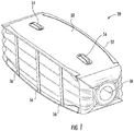
FIG. 1 is perspective view of a portion of a floatation device according to an embodiment; -
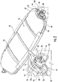
FIG. 2 is a perspective view of a floatation device in a retracted configuration according to an embodiment; -
FIG. 3 is a perspective view of a floatation device in an extended configuration according to an embodiment; -
FIGS. 4A and4B are perspective views of a portion of stiffener assembly according to an embodiment; -
FIGS. 5A and5B are perspective view of a stiffener assembly in a first and second configuration according to an embodiment; -
FIG. 6 is a perspective view of a valve assembly of the floatation device according to an embodiment; -
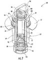
FIG. 7 is a partially cut away perspective view of a valve assembly of the floatation device according to an embodiment; -
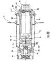
FIG. 8 is a plan view of a valve assembly of the floatation device according to an embodiment; -
FIG. 8A is a cross-sectional view of the valve assembly ofFIG. 8 taken along line A-A according to an embodiment; -
FIG. 8B is a cross-sectional view of the valve assembly ofFIG. 8 taken along line B-B according to an embodiment; -
FIG. 9 is a flow diagram illustrating a method of stowing a floatation device according to an embodiment; -
FIG. 10 is a cross-sectional view of the valve assembly of the floatation device when in an extended configuration according to an embodiment; -
FIG. 11 is a cross-sectional view of the valve assembly of the floatation device during manual inflation using a plunger according to an embodiment; and -
FIG. 12 is a perspective view of a plunger according to an embodiment. - A detailed description of one or more embodiments of the disclosed apparatus and method are presented herein by way of exemplification and not limitation with reference to the Figures.
- Referring now to the
FIGS. 1-3 , an example of a floatation device orfloat 20 is illustrated. Thefloatation device 20 is configured to transform between a first, retracted configuration (FIG. 2 ) and a second, extended configuration (FIGS. 1 and3 ). In the retracted configuration, thefloatation device 20 may be generally flattened and folded for storage, such as within a container for example. In the extended configuration, thefloatation device 20 is generally filled with air or another gas to achieve a sufficient level of buoyancy required for an application. Astiffener assembly 22 is operable to automatically transform thefloatation device 20 from the retracted configuration to the extended configuration. - An example of the
stiffener assembly 22 is illustrated in more detail inFIGS. 4 and 5 . Thestiffener assembly 22 includes afirst stiffener 24 and asecond stiffener 26 configured to cooperate with one another in a manner similar to a scissor mechanism to transition between a first configuration and a second configuration. Thefirst stiffener 24 includes at least onefirst member 28. In the illustrated, non-limiting embodiment, thestiffener assembly 22 includes a pair of substantially identicalfirst members 28 arranged generally parallel and offset from one another and in vertical alignment. In such embodiments, the pair offirst members 28 are rotated 180 degrees relative to one another such that a first surface of thefirst members 28 face towards one another. A pair of substantially identical firststructural connectors 30 extend between and connect a first side of the pair offirst members 28 and a second side of the pair offirst members 28, respectively. - The
second stiffener 26 similarly includes at least onesecond member 32. In an embodiment, the at least onesecond member 32 includes a pair of substantially identicalsecond members 32 arranged parallel to and offset from one another in vertical alignment. The pair ofsecond members 32 may additionally be rotated 180 degrees relative to one another. Further, a pair of substantially identical secondstructural connectors 34 extends between and connects a first side of the pair ofsecond members 32 and a second side of the pair ofsecond members 32, respectively. The firststructural connectors 30 of thefirst stiffener 24 and the secondstructural connectors 34 of thesecond stiffener 26 may, but need not be substantially identical to one another. In an embodiment, the first and secondstructural connectors - Each of the
first members 28 includes afirst arm 40 and asecond arm 42 extending therefrom. Similarly, each of thesecond members 32 has afirst arm 44 and asecond arm 46 extending therefrom. The at least onesecond member 32 is arranged in overlapping arrangement with the at least onefirst member 28. For example, thesecond member 32 may have a contour complementary to and configured to receive a flange extending from thefirst member 28. - The at least one
second member 32 is configured to rotate relative to thefirst members 28 between a first configuration and a second configuration. In an embodiment, a torsion spring 48 (seeFIG. 4B ) is positioned at the interface between afirst member 28 and a correspondingsecond member 32. The torsion spring is configured to bias the stiffener assembly into the second configuration. - In the first configuration, shown in
FIGS. 4A and 5A , thefirst arm 40 of thefirst member 28 is positioned generally adjacent thefirst arm 44 of thesecond member 32 and thesecond arm 42 of thefirst member 28 is positioned generally adjacent thesecond arm 46 of thesecond member 32 such that the firststructural connectors 30 and the secondstructural connectors 34 are generally parallel. However, the spring or biasing force of the structural connectors is configured to bias the assembly to a second configuration, illustrated inFIGS. 4B and 5B . As shown, in the second configuration, thesecond arm 46 of thesecond member 32 is arranged generally adjacent thefirst arm 40 of thefirst member 28, and thefirst arm 44 of thesecond member 32 is arranged generally adjacent thesecond arm 42 of thefirst member 28. Accordingly, in this second, rotated configuration, the secondstructural connectors 34 are arranged at an angle to the firststructural connectors 30. In an embodiment, the angle formed between the secondstructural connectors 34 and the firststructural connectors 30 is between about 60 degrees and about 120 degrees, such as about 90 degrees for example. - With reference again to
FIGS. 1-3 , askin 50 is connected to thestiffener assembly 22. Accordingly, movement of thestiffener assembly 22 between the first configuration and the second configuration causes thefloatation device 20 to transition between the retracted position and the extended position, respectively. Theskin 50 is shaped to define an interior cavity capable of being filled with air when thefloat 20 is extended and releasing air to retract thefloat 20. - The
skin 50 may be formed from any suitable air tight material, such as is used in other known inflatable floatation devices for use in water safety rescue applications. In an embodiment, as best shown inFIG. 2 , thestructural connectors stiffener assembly 22 are arranged about an exterior of theskin 50. However, it should be understood that embodiments where theskin 50 wraps about an exterior of thestructural connectors structural connectors skin 50 from being damaged or thestructural connectors - In an embodiment,
patches 52 are used to provide reinforcement at the interface between theskin 50 and a correspondingstructural connector patches 52 may be adhered to the surface of theskin 50, or alternatively, may be mechanically fastened thereto. In an embodiment, one or more handles or grips 54 is mounted to the exterior of the skin. Thehandle 54 is intended to allow a user to easy grasp and maneuver the floatation device when deployed. - When the
floatation device 20 is in a retracted position, the length of theskin 50 extending between thestructural connector 30, coupling thefirst arms 40 of thefirst members 28 and thestructural connector 34 connected to thesecond arms 46 of thesecond member 32 is greater than the distance between thosestructural connectors floatation device 20 is extended. This difference is length will vary based on the angle between thestructural members skin 50 when thefloat 20 is deployed, one or moreelastic bands 56 extends across this elongated length betweenstructural members elastic bands 56 are sized such that when thefloatation device 20 is in the retracted configuration, theelastic bands 56 are extended beyond normal length. Accordingly, the biasing or tension force of theelastic bands 56 urges theskin 50 towards the extended position. - Referring now to
FIGS. 6-8 , thefloatation device 20 additionally includes at least onevalve assembly 60. Ahousing 62 of thevalve assembly 60 may be formed from a lightweight, durable material, such as plastic for example. As shown, thehousing 62 includes a complementaryrear housing 64 andfront housing 66. Therear housing 64 may be located within anopening 58 formed in theskin 50 of thefloatation device 20, and thefront housing 66 may extend beyond the exterior of theskin 50. In the illustrated, non-limiting embodiment, afirst end 68 of thefront housing 66 is receivable within thefirst end 70 of therear housing 64 in an overlapping arrangement. However, ahousing 62 having another configuration, such as where the first ends 68, 70 of the front andrear housing front housing 66 and therear housing 64 are integrally formed, are also contemplated herein. An outwardly extending sealingflange 72 may be mounted adjacent thefirst end 70 of therear housing 64 to substantially seal theopening 58 in theskin 50 so that no fluid can flow between the exterior of thehousing 62 and the interior of theopening 58. - The overlapping
first member 28 andsecond member 32 of thestiffener assembly 22 are positioned about the exterior surface of thefront housing 66. Accordingly, in embodiments including two pairs of first andsecond members distinct valve assembly 60 may be located at opposing ends of thefloatation device 20. In an embodiment, a groove orkeyway 74 is formed in a portion of the first member 28 (seeFIGS. 4A and4B ). When thefirst member 28 is coupled to thefront housing 66, a flange ortooth 76 extending outwardly from the exterior of thefront housing 66 is received within thekeyway 74 to restrict rotation of thefirst member 28 relative to thevalve assembly 60. - Together the front and
rear housings hollow chamber 78. Asecond chamber 80 formed in therear housing 64 may be arranged in fluid communication withfirst chamber 78 and the interior cavity of thefloat 20. Aplunger 82 is arranged within the interior of thehousing 62 and extends between the first andsecond chambers first end 84 of theplunger 82 extends beyond thefront housing 66, outside thefirst chamber 78. In an embodiment, ahandle 86 is mounted about thefirst end 84 of theplunger 82 for manipulation thereof. Abiasing mechanism 88, such as a coil spring for example, is coupled to a second,opposite end 90 of theplunger 82 and is configured to bias theplunger 82 to a default position relative to thefirst chamber 78. - A
cylinder 92 is arranged within the interior of a portion of theplunger 82. In an embodiment, apull knob 94 extends from thefirst end 95 of thecylinder 92 beyond the adjacentfirst end 84 of theplunger 82. Thepull knob 94 may, but need not be, oriented substantially perpendicular to thehandle 86 as shown in the FIGS. Formed at the second end of thecylinder 92 is a first valve V1 movable to form a seal against a correspondingsurface 96 of theplunger 82. Anotherbiasing mechanism 98 is positioned between a portion of theplunger 82 and thecylinder 92. Thebiasing mechanism 98 is operable to bias thecylinder 92 into a default position relative to theplunger 82. In an embodiment, in the default position, the first valve V1 is in sealing engagement withsurface 96 of theplunger 82. - A groove, best shown in
FIGS. 7 and8B , is formed about a circumference of thecylinder 92. Atrigger pin 102 is movably mounted to thefront housing 64 in alignment with the groove 100. When a portion of thetrigger pin 102 is received within and engages the groove 100, thetrigger pin 102 opposes the biasing force of thebiasing mechanism 98 to retain the first valve V1 in a position offset from acorresponding engagement surface 96. Abiasing mechanism 104 is coupled to thetrigger pin 102 and is configured to move thetrigger pin 102 out of engagement with thecylinder 92. Accordingly, upon movement of thetrigger pin 102, thecylinder 92 is movable towardsurface 96 in response to the biasing force of thebiasing mechanism 98. - In an embodiment, the
second members 32 of thestiffener assembly 22 include aflange 106 extending from a surface thereof (seeFIGS. 4A and4B ). When thesecond member 32 is in the first position, theflange 106 is configured to oppose the biasing force ofmechanism 104, thereby restricting movement of thetrigger pin 102 from the groove 100. Upon deployment of thestiffener assembly 22, as thesecond member 32 rotates relative to thehousing 64 and thefirst member 28, theflange 106 rotates out of engagement with thetrigger pin 102. - A second valve V2 is positioned within an interior portion of the
plunger 82, for example adjacent thesecond end 90 thereof. The second valve V2 is similarly movable to form a seal against acorresponding surface 108 of theplunger 82. Abiasing mechanism 110 extends between the second valve V2 and an interior surface of theplunger 82. Thebiasing mechanism 110 is configured to bias the second valve V2 to a position where the second valve V2 is sealed against thesurface 108 of theplunger 82. - In an embodiment, the first valve V1 and the second valve V2 are operably coupled via a
cam mechanism 112 rotatably mounted within theplunger 82 via apin 114. Accordingly, the first valve V1 and the second valve V2 are configured to move between a sealed position and an unsealed position generally in unison. As a result, application of a force to thecylinder 92 opposing the biasing force of thebiasing mechanism 98, such as via thetrigger pin 102 for example, may be transmitted to the second valve V2 via thecam mechanism 112. The rotation of the arms of thecam mechanism 112 applies a similar force to the second valve V2 in a direction opposing thebiasing mechanism 110 coupled thereto. Upon release of the opposing force, both biasingmechanisms - A third valve V3 is mounted to a
second end 116 of therear housing 64 and is operable to selectively seal the interface between thefirst chamber 78 and thesecond chamber 80. Abiasing mechanism 118 is operably coupled to the third valve V3 to bias the valve into sealing engagement with anadjacent surface 120, such as an adjacent surface of thehousing 64 for example. At least one fourth valve V4 positioned within a channel defined by thehousing 62 selectively seals anopening 122 formed in thehousing 62. Abiasing mechanism 124 associated with the at least one fourth valve V4 is biased into sealing engagement with thehousing 62 adjacent theopening 122 to block a flow of air through the chamber and into thefirst chamber 78. - With reference now to
FIG. 9 , thefloatation device 20 should be stored within a container to maintain the float in the retracted configuration. To store theflotation device 20, once the air has been removed from the interior cavity and thestiffener assembly 22 has been transformed to the first position where the pairs of first and secondstructural members float 20. Again, the second portion of thefloatation device 20 that is twisted may be about one third of the float. As a result, each portion of thefloatation device 20 formed by the various twisting and folding operations is substantially identical. In an embodiment, once both the first and second portions have been folded over, thefloat 20 has a generally circular or rounded shape, and thevalve assemblies 60 extend from opposing sides thereof. In this compact configuration, thefloatation device 20 may be positioned within a container, such as a zippered bag for example, to stow and retain the position within this retracted and folded configuration. - When the float is in the retracted position, the first valve VI, second valve V2, and third valve V3 of the valve assemblies are all open and the fourth valve V4 is closed. As a result, fluid is able to flow through the first, second, and third valves into the interior cavity of the
floatation device 20. Once thefloatation device 20 is removed from the storage container, the spring force of the twistedstructural connectors floatation device 20 not only to untwist, but also to transform from the flattened, retracted configuration to the extended configuration due to the biasing force of the torsion spring of thestiffener assembly 22 and theelastic bands 56 attached to the skin. As thedevice 20 expands, a partial vacuum is created within the interior of thedevice 20. Further, thesecond member 32 of thestiffener assembly 22 moves relative to thehousing 62, out of engagement with thetrigger pin 102. As a result, the biasing force of thebiasing mechanism 104 coupled to thetrigger pin 102 moves thetrigger pin 102 out of engagement with the groove 100 formed in thecylinder 92, causing the first valve VI, and therefore the second valve V2 to bias into a sealed position. The sealed position of the first and second valves V1 and V2 will block a flow of air or another fluid into and out of from the interior of thedevice 20. Accordingly, in this extended configuration, thefloat 20 may be used in water. - After being deployed, in the extended position, the
floatation device 20 may be manually inflated to a point where the pressure within the interior of thefloat 20 is equal to the atmospheric pressure. Application of a force to thepull knob 94 will cause thecylinder 92 to translate within theplunger 82 in a direction opposite the force of thebiasing mechanism 98. As the first valve V1 moves out of sealing engagement withsurface 96 the second valve V2 is similarly translated away fromsurface 108, due to the rotation of thecam mechanism 112 connected to the first and second valves VI, V2 (seeFIG. 8A ),. With the first and second valves VI, V2 open, air will flow into the interior of thefloatation device 20, allowing the pressure within the chamber and the atmospheric pressure to equalize. Accordingly, the first valve VI, second valve V2 and third valve V3 are open during operation of thepull knob 94. Upon release of thepull knob 94, the biasing force of thebiasing mechanism 98 will cause the first valve VI, and therefore the second valve V2, to bias back into a sealed position to block a flow or air into or out of the device 20 (seeFIG. 10 ). In addition, the first and second valves V1, V2, prevent water from entering the inside of thefloatation device 20 when the pressure of the float is less than or equal to then ambient pressure. - Alternatively, the
floatation device 20 may be manually inflated using thehandle 86, as shown inFIG. 11 . Thehandle 86 provides a mechanism for moving theplunger 82 back and forth relative to thehousing 62 in a manner similar to a "pump." As theplunger 82 is pulled outwardly relative to thehousing 62, a vacuum is created within thefirst chamber 78. This causes air to rush through the bypass valve V4, and through anair inlet 126 into thefirst chamber 78. In addition, movement of theplunger 82 relative to thehousing 62 causes the third valve V3 to bias into sealing engagement with an adjacent surface. When a force is applied to thehandle 86 to reposition the plunger within thefirst chamber 78, the pressure generated within the first chamber acts on the third valve V3. The pressure causes the third valve V3 to open, and the bypass valve V4 to close, thereby allowing the air within thefirst chamber 78 to flow into thesecond chamber 80 and into the interior of the floatation device. This movement of the plunger can be repeated until a desired pressure is achieved within the interior of thefloat 20. - The
plunger 82 is additionally transformable between a locked position and an unlocked position. Theplunger 82 is operated to manually inflate thefloatation device 20 only when theplunger 82 is in the unlocked position. Theplunger 82 may be locked to prevent inadvertent transitioning between the retracted and extended positions. Thefloatation device 20 will not function properly if theplunger 82 is inadvertently unlocked when thefloat 20 is deployed because water will enter the interior cavity of thefloat 20. - The
plunger 82 may be retained in the locked position via thebiasing mechanism 88. Thebiasing mechanism 88 applies a force to theplunger 82 so as to prevent rotation of theplunger 82 due to vibration. In an embodiment, movement of theplunger 82 relative to thehousing 62 is also restricted via engagement with thetrigger pin 102. With reference toFIG. 12 , aguide channel 130 may be formed in a side of theplunger 82. In the illustrated, non-limiting embodiment, theguide channel 130 is generally T-shaped, however, a guide channel having any suitable configuration, such as an L-shape for example is contemplated herein. When theplunger 82 is positioned within thehousing 62, thetrigger pin 102 is arranged within a portion of theguide channel 130 that restricts translational movement of theplunger 80. - To transition the
plunger 82 to an unlocked position for manual inflation, theplunger 82 is rotated about an axis relative to thehousing 62. In an embodiment, a force must be applied to theplunger 82 opposing the bias of thebiasing mechanism 88 in order to release theplunger 82 from its locked position. In some embodiments, a visual indicator is mounted on thefront housing 66. The visual indicator is configured to provide a user with information related to the status of theplunger 82, such as whether theplunger 82 is in a locked or unlocked position for example. - It should be understood that the
floatation device 20 disclosed herein may additionally comprise a pressurized container configured to supplement the pressure within interior cavity after the float has been deployed. Further, the pressurized container may be operated in addition to the valve assembly, or in some embodiments, instead of the valve assembly. - The
floatation device 20 illustrated and described herein is configured to automatically inflate upon release from a container. Because this inflation occurs in the absence of a pressurized supply of air or gas, thefloatation device 20 has a reduced weight and may be continuously reused. Further, thefloatation device 20 has improved stability against buckling when at a reduced pressure due to thesprings skin 50. - The term "about" is intended to include the degree of error associated with measurement of the particular quantity based upon the equipment available at the time of filing the application. For example, "about" can include a range of ± 8% or 5%, or 2% of a given value.
- The terminology used herein is for the purpose of describing particular embodiments only and is not intended to be limiting of the present disclosure. As used herein, the singular forms "a", "an" and "the" are intended to include the plural forms as well, unless the context clearly indicates otherwise. It will be further understood that the terms "comprises" and/or "comprising," when used in this specification, specify the presence of stated features, integers, steps, operations, elements, and/or components, but do not preclude the presence or addition of one or more other features, integers, steps, operations, element components, and/or groups thereof.
- While the present disclosure has been described with reference to an exemplary embodiment or embodiments, it will be understood by those skilled in the art that various changes may be made and equivalents may be substituted for elements thereof without departing from the scope of the present invention as defined by the claims. In addition, many modifications may be made to adapt a particular situation or material to the teachings of the present disclosure without departing from the scope thereof. Therefore, it is intended that the present disclosure not be limited to the particular embodiment disclosed as the best mode contemplated for carrying out this present disclosure, but that the present disclosure will include all embodiments falling within the scope of the claims.
Claims (15)
- A floatation device comprising:a body (20) transformable between a retracted configuration and an extended configuration; anda stiffener assembly (22) movable between a first position and a second position, the stiffener assembly being biased into the second position, wherein the stiffener assembly is operably coupled to the body, such that movement of the stiffener assembly between the first position and the second position causes the body to transform between the retracted position and the extended position;wherein during the transformation of the body between the retracted position and the extended position, a partial vacuum is created within the body to inflate the floatation device.
- The floatation device of claim 1, further comprising a mechanism (94) for manually inflating the body when the body is in the extended configuration.
- The floatation device of claim 2, wherein the mechanism is operable to inflate the body to a pressure substantially equal to an ambient atmospheric pressure.
- The floatation device of claim 2, wherein the mechanism is operable to pump air into the body.
- The floatation device of claim 1, wherein the stiffener assembly includes:a pair of first members (28) operably coupled together by a pair of first structural connectors (30); anda pair of second members (32) operably coupled together by a pair of second structural connectors (34), each second member being disposed in overlapping arrangement with one of the pair of first members, the second members being rotatable relative to the first members.
- The floatation device of claim 5, wherein in the first position, the pair of first structural connectors and the pair of second structural connectors are substantially parallel.
- The floatation device of claim 5, wherein the pair of first structural connectors and the pair of second structural connectors are formed from a resilient material.
- The floatation device of any preceding claim, wherein the body includes a skin (50) configured to define an interior cavity, the stiffener assembly being operably coupled to the skin; and
the floatation device further comprises a valve assembly (60) arranged in fluid communication with the interior cavity, the valve assembly being coupled to the stiffener assembly. - The floatation device of claim 8, wherein movement of the stiffener assembly to the second position causes at least one valve of the valve assembly to seal and block a flow into and out of the interior cavity.
- The floatation device of claim 8, wherein the valve assembly comprises at least a first valve (V1) and a second valve (V2) operably coupled to one another, the first valve and the second valve being movable to selectively control a flow into and out of the interior cavity.
- A method of inflating a floatation device, comprising:biasing a stiffener assembly from a first position to a second position such that the floatation device transitions from a retracted position to an extended position;creating a partial vacuum within an interior cavity of the floatation device causing air to be drawn therein; andsealing at least one valve of a valve assembly of the floatation device to block a flow of air into and out of the interior cavity.
- The method of claim 11, further comprising removing the floatation device from a storage container.
- The method of claim 11, further comprising manually inflating the floatation device when in the extended configuration.
- The method of claim 13, wherein manually inflating the floatation device includes opening at least one valve of the valve assembly to allow air to flow into the interior cavity.
- The method of claim 13, wherein manually inflating the floatation device includes repeatedly translating a plunger of the valve assembly to form a pumping mechanism.
Applications Claiming Priority (1)
| Application Number | Priority Date | Filing Date | Title |
|---|---|---|---|
| IN201711010271 | 2017-03-23 |
Publications (2)
| Publication Number | Publication Date |
|---|---|
| EP3378755A1 true EP3378755A1 (en) | 2018-09-26 |
| EP3378755B1 EP3378755B1 (en) | 2020-04-29 |
Family
ID=61749953
Family Applications (1)
| Application Number | Title | Priority Date | Filing Date |
|---|---|---|---|
| EP18163159.9A Active EP3378755B1 (en) | 2017-03-23 | 2018-03-21 | Floatation device without pressurized container |
Country Status (2)
| Country | Link |
|---|---|
| US (1) | US10266243B2 (en) |
| EP (1) | EP3378755B1 (en) |
Families Citing this family (1)
| Publication number | Priority date | Publication date | Assignee | Title |
|---|---|---|---|---|
| US12448096B2 (en) * | 2023-02-02 | 2025-10-21 | Lary Z Enterprises, Inc. | Weight pocket liner for buoyancy control device (BCD) |
Citations (6)
| Publication number | Priority date | Publication date | Assignee | Title |
|---|---|---|---|---|
| DE58889C (en) * | F. REIMANN in Berlin, Perlebergerstr. 26k, und W. SCHLAMEÜSS in Berlin, Königgrätzerstr. 10 | Collapsible float | ||
| US205617A (en) * | 1878-07-02 | Improvement in life-preserving satchels | ||
| WO1985002156A1 (en) * | 1983-11-21 | 1985-05-23 | Hoch, Karl | Inflatable hollow body |
| DE4034593A1 (en) * | 1990-10-31 | 1992-07-30 | Marek Dipl Ing Zagorski | Integral air pump for inflatable prods. - has chamber filled with resilient insert |
| US20040222684A1 (en) * | 2002-11-22 | 2004-11-11 | Schukra Of North America | Self inflating pneumatic seat cushion apparatus and method |
| WO2005049384A1 (en) * | 2003-11-20 | 2005-06-02 | Georges Kach | Self-inflatable devices used in the form of floats and/or impact energy absorbers |
Family Cites Families (12)
| Publication number | Priority date | Publication date | Assignee | Title |
|---|---|---|---|---|
| US3339218A (en) | 1965-05-05 | 1967-09-05 | Stamberger Paul | Self-inflatable hollow bodies for use as floats and for like purposes |
| US3378864A (en) | 1966-02-18 | 1968-04-23 | Phil M. Cornes | Atmospherically self-inflating buoyant device |
| GB1152631A (en) * | 1967-01-05 | 1969-05-21 | Frankenstein Group Ltd | Improvements in or relating to Inflatable-Attachments for Marine Lifesaving |
| US3643268A (en) * | 1970-09-30 | 1972-02-22 | Paul Stamberger | Self-inflatable hollow bodies for use as cushions and for like purposes |
| US4521166A (en) * | 1981-11-02 | 1985-06-04 | Phillips William E | Inflatable air pump |
| HK1074968A2 (en) * | 2004-08-04 | 2005-11-25 | The Licensing Group, Inc. | Exercise device |
| US20060037145A1 (en) * | 2004-08-18 | 2006-02-23 | Cheng-Chung Wang | Self-inflating mattress |
| US20060270290A1 (en) | 2005-05-25 | 2006-11-30 | TELLEW John | Lightweight personal rescue tube flotation device |
| US7458120B2 (en) * | 2006-08-22 | 2008-12-02 | Hsien-Wen Chang | Inflatable item with a valve attached thereto |
| US8016627B2 (en) | 2007-11-19 | 2011-09-13 | West Neck Partners, Inc. | Personal water safety device |
| US20110089741A1 (en) * | 2009-10-15 | 2011-04-21 | Randolph Lee Cyr | Self inflating bellows chair |
| US8408959B2 (en) * | 2009-12-24 | 2013-04-02 | David Hirbe Wickham | Collapsible floatation system |
-
2017
- 2017-07-07 US US15/644,366 patent/US10266243B2/en active Active
-
2018
- 2018-03-21 EP EP18163159.9A patent/EP3378755B1/en active Active
Patent Citations (6)
| Publication number | Priority date | Publication date | Assignee | Title |
|---|---|---|---|---|
| DE58889C (en) * | F. REIMANN in Berlin, Perlebergerstr. 26k, und W. SCHLAMEÜSS in Berlin, Königgrätzerstr. 10 | Collapsible float | ||
| US205617A (en) * | 1878-07-02 | Improvement in life-preserving satchels | ||
| WO1985002156A1 (en) * | 1983-11-21 | 1985-05-23 | Hoch, Karl | Inflatable hollow body |
| DE4034593A1 (en) * | 1990-10-31 | 1992-07-30 | Marek Dipl Ing Zagorski | Integral air pump for inflatable prods. - has chamber filled with resilient insert |
| US20040222684A1 (en) * | 2002-11-22 | 2004-11-11 | Schukra Of North America | Self inflating pneumatic seat cushion apparatus and method |
| WO2005049384A1 (en) * | 2003-11-20 | 2005-06-02 | Georges Kach | Self-inflatable devices used in the form of floats and/or impact energy absorbers |
Also Published As
| Publication number | Publication date |
|---|---|
| US10266243B2 (en) | 2019-04-23 |
| US20180273150A1 (en) | 2018-09-27 |
| EP3378755B1 (en) | 2020-04-29 |
Similar Documents
| Publication | Publication Date | Title |
|---|---|---|
| EP2114763B1 (en) | Inflatable fender for a boat | |
| US9533757B2 (en) | Buoyancy system for an aircraft | |
| US3841256A (en) | Device for temporarily sealing holes in boats | |
| EP3378755B1 (en) | Floatation device without pressurized container | |
| US3934292A (en) | Triggering devices | |
| CN113697066B (en) | Ship lifesaving device | |
| US4058862A (en) | Water safety device | |
| US7207522B2 (en) | Safety device trigger for activating a safety device | |
| WO2011008536A2 (en) | Method of and apparatus for bouyancy compensation for divers | |
| KR102351443B1 (en) | Lifesaving throwable tube | |
| US3102705A (en) | Flotation device | |
| US3992739A (en) | Water safety device | |
| EP4244129A1 (en) | Inflatable salvage bag | |
| GB2126171A (en) | Inflatable life-raft | |
| WO2005095203A1 (en) | Safe swim suit | |
| CN110356532A (en) | A kind of life jacket | |
| IT201700010263A1 (en) | EXTENSIBLE RESCUE DEVICE | |
| US4731037A (en) | Water survival kit | |
| US7887382B1 (en) | Multipurpose water rescue apparatus | |
| US1765002A (en) | Pneumatic water craft | |
| GB2224979A (en) | Emergency buoyancy system | |
| GB2569882A (en) | A valve for an inflatable article | |
| US3489318A (en) | Buoyancy system | |
| US1890405A (en) | Submarine salvage apparatus | |
| CN117916152A (en) | Protection device for protecting ship hull comprising inflatable anti-collision element |
Legal Events
| Date | Code | Title | Description |
|---|---|---|---|
| PUAI | Public reference made under article 153(3) epc to a published international application that has entered the european phase |
Free format text: ORIGINAL CODE: 0009012 |
|
| STAA | Information on the status of an ep patent application or granted ep patent |
Free format text: STATUS: THE APPLICATION HAS BEEN PUBLISHED |
|
| AK | Designated contracting states |
Kind code of ref document: A1 Designated state(s): AL AT BE BG CH CY CZ DE DK EE ES FI FR GB GR HR HU IE IS IT LI LT LU LV MC MK MT NL NO PL PT RO RS SE SI SK SM TR |
|
| AX | Request for extension of the european patent |
Extension state: BA ME |
|
| STAA | Information on the status of an ep patent application or granted ep patent |
Free format text: STATUS: REQUEST FOR EXAMINATION WAS MADE |
|
| 17P | Request for examination filed |
Effective date: 20190325 |
|
| RBV | Designated contracting states (corrected) |
Designated state(s): AL AT BE BG CH CY CZ DE DK EE ES FI FR GB GR HR HU IE IS IT LI LT LU LV MC MK MT NL NO PL PT RO RS SE SI SK SM TR |
|
| GRAP | Despatch of communication of intention to grant a patent |
Free format text: ORIGINAL CODE: EPIDOSNIGR1 |
|
| STAA | Information on the status of an ep patent application or granted ep patent |
Free format text: STATUS: GRANT OF PATENT IS INTENDED |
|
| INTG | Intention to grant announced |
Effective date: 20191018 |
|
| GRAS | Grant fee paid |
Free format text: ORIGINAL CODE: EPIDOSNIGR3 |
|
| GRAA | (expected) grant |
Free format text: ORIGINAL CODE: 0009210 |
|
| STAA | Information on the status of an ep patent application or granted ep patent |
Free format text: STATUS: THE PATENT HAS BEEN GRANTED |
|
| AK | Designated contracting states |
Kind code of ref document: B1 Designated state(s): AL AT BE BG CH CY CZ DE DK EE ES FI FR GB GR HR HU IE IS IT LI LT LU LV MC MK MT NL NO PL PT RO RS SE SI SK SM TR |
|
| REG | Reference to a national code |
Ref country code: GB Ref legal event code: FG4D |
|
| REG | Reference to a national code |
Ref country code: CH Ref legal event code: EP |
|
| REG | Reference to a national code |
Ref country code: AT Ref legal event code: REF Ref document number: 1262922 Country of ref document: AT Kind code of ref document: T Effective date: 20200515 |
|
| REG | Reference to a national code |
Ref country code: DE Ref legal event code: R096 Ref document number: 602018004083 Country of ref document: DE |
|
| REG | Reference to a national code |
Ref country code: IE Ref legal event code: FG4D |
|
| REG | Reference to a national code |
Ref country code: NL Ref legal event code: MP Effective date: 20200429 |
|
| REG | Reference to a national code |
Ref country code: LT Ref legal event code: MG4D |
|
| PG25 | Lapsed in a contracting state [announced via postgrant information from national office to epo] |
Ref country code: IS Free format text: LAPSE BECAUSE OF FAILURE TO SUBMIT A TRANSLATION OF THE DESCRIPTION OR TO PAY THE FEE WITHIN THE PRESCRIBED TIME-LIMIT Effective date: 20200829 Ref country code: PT Free format text: LAPSE BECAUSE OF FAILURE TO SUBMIT A TRANSLATION OF THE DESCRIPTION OR TO PAY THE FEE WITHIN THE PRESCRIBED TIME-LIMIT Effective date: 20200831 Ref country code: LT Free format text: LAPSE BECAUSE OF FAILURE TO SUBMIT A TRANSLATION OF THE DESCRIPTION OR TO PAY THE FEE WITHIN THE PRESCRIBED TIME-LIMIT Effective date: 20200429 Ref country code: SE Free format text: LAPSE BECAUSE OF FAILURE TO SUBMIT A TRANSLATION OF THE DESCRIPTION OR TO PAY THE FEE WITHIN THE PRESCRIBED TIME-LIMIT Effective date: 20200429 Ref country code: GR Free format text: LAPSE BECAUSE OF FAILURE TO SUBMIT A TRANSLATION OF THE DESCRIPTION OR TO PAY THE FEE WITHIN THE PRESCRIBED TIME-LIMIT Effective date: 20200730 Ref country code: NO Free format text: LAPSE BECAUSE OF FAILURE TO SUBMIT A TRANSLATION OF THE DESCRIPTION OR TO PAY THE FEE WITHIN THE PRESCRIBED TIME-LIMIT Effective date: 20200729 Ref country code: FI Free format text: LAPSE BECAUSE OF FAILURE TO SUBMIT A TRANSLATION OF THE DESCRIPTION OR TO PAY THE FEE WITHIN THE PRESCRIBED TIME-LIMIT Effective date: 20200429 |
|
| REG | Reference to a national code |
Ref country code: AT Ref legal event code: MK05 Ref document number: 1262922 Country of ref document: AT Kind code of ref document: T Effective date: 20200429 |
|
| PG25 | Lapsed in a contracting state [announced via postgrant information from national office to epo] |
Ref country code: BG Free format text: LAPSE BECAUSE OF FAILURE TO SUBMIT A TRANSLATION OF THE DESCRIPTION OR TO PAY THE FEE WITHIN THE PRESCRIBED TIME-LIMIT Effective date: 20200729 Ref country code: LV Free format text: LAPSE BECAUSE OF FAILURE TO SUBMIT A TRANSLATION OF THE DESCRIPTION OR TO PAY THE FEE WITHIN THE PRESCRIBED TIME-LIMIT Effective date: 20200429 Ref country code: HR Free format text: LAPSE BECAUSE OF FAILURE TO SUBMIT A TRANSLATION OF THE DESCRIPTION OR TO PAY THE FEE WITHIN THE PRESCRIBED TIME-LIMIT Effective date: 20200429 Ref country code: RS Free format text: LAPSE BECAUSE OF FAILURE TO SUBMIT A TRANSLATION OF THE DESCRIPTION OR TO PAY THE FEE WITHIN THE PRESCRIBED TIME-LIMIT Effective date: 20200429 |
|
| PG25 | Lapsed in a contracting state [announced via postgrant information from national office to epo] |
Ref country code: AL Free format text: LAPSE BECAUSE OF FAILURE TO SUBMIT A TRANSLATION OF THE DESCRIPTION OR TO PAY THE FEE WITHIN THE PRESCRIBED TIME-LIMIT Effective date: 20200429 Ref country code: NL Free format text: LAPSE BECAUSE OF FAILURE TO SUBMIT A TRANSLATION OF THE DESCRIPTION OR TO PAY THE FEE WITHIN THE PRESCRIBED TIME-LIMIT Effective date: 20200429 |
|
| PG25 | Lapsed in a contracting state [announced via postgrant information from national office to epo] |
Ref country code: AT Free format text: LAPSE BECAUSE OF FAILURE TO SUBMIT A TRANSLATION OF THE DESCRIPTION OR TO PAY THE FEE WITHIN THE PRESCRIBED TIME-LIMIT Effective date: 20200429 Ref country code: CZ Free format text: LAPSE BECAUSE OF FAILURE TO SUBMIT A TRANSLATION OF THE DESCRIPTION OR TO PAY THE FEE WITHIN THE PRESCRIBED TIME-LIMIT Effective date: 20200429 Ref country code: ES Free format text: LAPSE BECAUSE OF FAILURE TO SUBMIT A TRANSLATION OF THE DESCRIPTION OR TO PAY THE FEE WITHIN THE PRESCRIBED TIME-LIMIT Effective date: 20200429 Ref country code: RO Free format text: LAPSE BECAUSE OF FAILURE TO SUBMIT A TRANSLATION OF THE DESCRIPTION OR TO PAY THE FEE WITHIN THE PRESCRIBED TIME-LIMIT Effective date: 20200429 Ref country code: IT Free format text: LAPSE BECAUSE OF FAILURE TO SUBMIT A TRANSLATION OF THE DESCRIPTION OR TO PAY THE FEE WITHIN THE PRESCRIBED TIME-LIMIT Effective date: 20200429 Ref country code: SM Free format text: LAPSE BECAUSE OF FAILURE TO SUBMIT A TRANSLATION OF THE DESCRIPTION OR TO PAY THE FEE WITHIN THE PRESCRIBED TIME-LIMIT Effective date: 20200429 Ref country code: EE Free format text: LAPSE BECAUSE OF FAILURE TO SUBMIT A TRANSLATION OF THE DESCRIPTION OR TO PAY THE FEE WITHIN THE PRESCRIBED TIME-LIMIT Effective date: 20200429 Ref country code: DK Free format text: LAPSE BECAUSE OF FAILURE TO SUBMIT A TRANSLATION OF THE DESCRIPTION OR TO PAY THE FEE WITHIN THE PRESCRIBED TIME-LIMIT Effective date: 20200429 |
|
| REG | Reference to a national code |
Ref country code: DE Ref legal event code: R097 Ref document number: 602018004083 Country of ref document: DE |
|
| PG25 | Lapsed in a contracting state [announced via postgrant information from national office to epo] |
Ref country code: SK Free format text: LAPSE BECAUSE OF FAILURE TO SUBMIT A TRANSLATION OF THE DESCRIPTION OR TO PAY THE FEE WITHIN THE PRESCRIBED TIME-LIMIT Effective date: 20200429 Ref country code: PL Free format text: LAPSE BECAUSE OF FAILURE TO SUBMIT A TRANSLATION OF THE DESCRIPTION OR TO PAY THE FEE WITHIN THE PRESCRIBED TIME-LIMIT Effective date: 20200429 |
|
| PLBE | No opposition filed within time limit |
Free format text: ORIGINAL CODE: 0009261 |
|
| STAA | Information on the status of an ep patent application or granted ep patent |
Free format text: STATUS: NO OPPOSITION FILED WITHIN TIME LIMIT |
|
| 26N | No opposition filed |
Effective date: 20210201 |
|
| PG25 | Lapsed in a contracting state [announced via postgrant information from national office to epo] |
Ref country code: SI Free format text: LAPSE BECAUSE OF FAILURE TO SUBMIT A TRANSLATION OF THE DESCRIPTION OR TO PAY THE FEE WITHIN THE PRESCRIBED TIME-LIMIT Effective date: 20200429 |
|
| PG25 | Lapsed in a contracting state [announced via postgrant information from national office to epo] |
Ref country code: MC Free format text: LAPSE BECAUSE OF FAILURE TO SUBMIT A TRANSLATION OF THE DESCRIPTION OR TO PAY THE FEE WITHIN THE PRESCRIBED TIME-LIMIT Effective date: 20200429 |
|
| REG | Reference to a national code |
Ref country code: CH Ref legal event code: PL |
|
| REG | Reference to a national code |
Ref country code: BE Ref legal event code: MM Effective date: 20210331 |
|
| PG25 | Lapsed in a contracting state [announced via postgrant information from national office to epo] |
Ref country code: LU Free format text: LAPSE BECAUSE OF NON-PAYMENT OF DUE FEES Effective date: 20210321 Ref country code: LI Free format text: LAPSE BECAUSE OF NON-PAYMENT OF DUE FEES Effective date: 20210331 Ref country code: IE Free format text: LAPSE BECAUSE OF NON-PAYMENT OF DUE FEES Effective date: 20210321 Ref country code: CH Free format text: LAPSE BECAUSE OF NON-PAYMENT OF DUE FEES Effective date: 20210331 |
|
| PG25 | Lapsed in a contracting state [announced via postgrant information from national office to epo] |
Ref country code: BE Free format text: LAPSE BECAUSE OF NON-PAYMENT OF DUE FEES Effective date: 20210331 |
|
| P01 | Opt-out of the competence of the unified patent court (upc) registered |
Effective date: 20230522 |
|
| PG25 | Lapsed in a contracting state [announced via postgrant information from national office to epo] |
Ref country code: CY Free format text: LAPSE BECAUSE OF FAILURE TO SUBMIT A TRANSLATION OF THE DESCRIPTION OR TO PAY THE FEE WITHIN THE PRESCRIBED TIME-LIMIT Effective date: 20200429 |
|
| PG25 | Lapsed in a contracting state [announced via postgrant information from national office to epo] |
Ref country code: HU Free format text: LAPSE BECAUSE OF FAILURE TO SUBMIT A TRANSLATION OF THE DESCRIPTION OR TO PAY THE FEE WITHIN THE PRESCRIBED TIME-LIMIT; INVALID AB INITIO Effective date: 20180321 |
|
| PG25 | Lapsed in a contracting state [announced via postgrant information from national office to epo] |
Ref country code: MK Free format text: LAPSE BECAUSE OF FAILURE TO SUBMIT A TRANSLATION OF THE DESCRIPTION OR TO PAY THE FEE WITHIN THE PRESCRIBED TIME-LIMIT Effective date: 20200429 |
|
| PG25 | Lapsed in a contracting state [announced via postgrant information from national office to epo] |
Ref country code: TR Free format text: LAPSE BECAUSE OF FAILURE TO SUBMIT A TRANSLATION OF THE DESCRIPTION OR TO PAY THE FEE WITHIN THE PRESCRIBED TIME-LIMIT Effective date: 20200429 |
|
| PG25 | Lapsed in a contracting state [announced via postgrant information from national office to epo] |
Ref country code: MT Free format text: LAPSE BECAUSE OF FAILURE TO SUBMIT A TRANSLATION OF THE DESCRIPTION OR TO PAY THE FEE WITHIN THE PRESCRIBED TIME-LIMIT Effective date: 20200429 |
|
| PGFP | Annual fee paid to national office [announced via postgrant information from national office to epo] |
Ref country code: GB Payment date: 20260219 Year of fee payment: 9 |
|
| PGFP | Annual fee paid to national office [announced via postgrant information from national office to epo] |
Ref country code: DE Payment date: 20260219 Year of fee payment: 9 |
|
| PGFP | Annual fee paid to national office [announced via postgrant information from national office to epo] |
Ref country code: FR Payment date: 20260219 Year of fee payment: 9 |