EP3378709A1 - Airbag for side collision - Google Patents
Airbag for side collision Download PDFInfo
- Publication number
- EP3378709A1 EP3378709A1 EP16866659.2A EP16866659A EP3378709A1 EP 3378709 A1 EP3378709 A1 EP 3378709A1 EP 16866659 A EP16866659 A EP 16866659A EP 3378709 A1 EP3378709 A1 EP 3378709A1
- Authority
- EP
- European Patent Office
- Prior art keywords
- head
- airbag
- occupant
- area
- side airbag
- Prior art date
- Legal status (The legal status is an assumption and is not a legal conclusion. Google has not performed a legal analysis and makes no representation as to the accuracy of the status listed.)
- Granted
Links
- 230000001681 protective effect Effects 0.000 claims abstract description 60
- 210000000038 chest Anatomy 0.000 description 21
- 239000004744 fabric Substances 0.000 description 9
- 230000000694 effects Effects 0.000 description 2
- 238000012986 modification Methods 0.000 description 2
- 230000004048 modification Effects 0.000 description 2
- 238000009958 sewing Methods 0.000 description 2
- 238000007792 addition Methods 0.000 description 1
- 238000006243 chemical reaction Methods 0.000 description 1
- 230000002452 interceptive effect Effects 0.000 description 1
- 210000004197 pelvis Anatomy 0.000 description 1
- 229920000728 polyester Polymers 0.000 description 1
- 238000006467 substitution reaction Methods 0.000 description 1
Images


Classifications
-
- B—PERFORMING OPERATIONS; TRANSPORTING
- B60—VEHICLES IN GENERAL
- B60R—VEHICLES, VEHICLE FITTINGS, OR VEHICLE PARTS, NOT OTHERWISE PROVIDED FOR
- B60R21/00—Arrangements or fittings on vehicles for protecting or preventing injuries to occupants or pedestrians in case of accidents or other traffic risks
- B60R21/02—Occupant safety arrangements or fittings, e.g. crash pads
- B60R21/16—Inflatable occupant restraints or confinements designed to inflate upon impact or impending impact, e.g. air bags
- B60R21/23—Inflatable members
- B60R21/231—Inflatable members characterised by their shape, construction or spatial configuration
- B60R21/23138—Inflatable members characterised by their shape, construction or spatial configuration specially adapted for side protection
-
- B—PERFORMING OPERATIONS; TRANSPORTING
- B60—VEHICLES IN GENERAL
- B60R—VEHICLES, VEHICLE FITTINGS, OR VEHICLE PARTS, NOT OTHERWISE PROVIDED FOR
- B60R21/00—Arrangements or fittings on vehicles for protecting or preventing injuries to occupants or pedestrians in case of accidents or other traffic risks
- B60R21/02—Occupant safety arrangements or fittings, e.g. crash pads
- B60R21/16—Inflatable occupant restraints or confinements designed to inflate upon impact or impending impact, e.g. air bags
- B60R21/20—Arrangements for storing inflatable members in their non-use or deflated condition; Arrangement or mounting of air bag modules or components
- B60R21/207—Arrangements for storing inflatable members in their non-use or deflated condition; Arrangement or mounting of air bag modules or components in vehicle seats
-
- B—PERFORMING OPERATIONS; TRANSPORTING
- B60—VEHICLES IN GENERAL
- B60R—VEHICLES, VEHICLE FITTINGS, OR VEHICLE PARTS, NOT OTHERWISE PROVIDED FOR
- B60R21/00—Arrangements or fittings on vehicles for protecting or preventing injuries to occupants or pedestrians in case of accidents or other traffic risks
- B60R21/02—Occupant safety arrangements or fittings, e.g. crash pads
- B60R21/16—Inflatable occupant restraints or confinements designed to inflate upon impact or impending impact, e.g. air bags
- B60R21/23—Inflatable members
- B60R21/231—Inflatable members characterised by their shape, construction or spatial configuration
- B60R21/2334—Expansion control features
- B60R21/2338—Tethers
-
- B—PERFORMING OPERATIONS; TRANSPORTING
- B60—VEHICLES IN GENERAL
- B60R—VEHICLES, VEHICLE FITTINGS, OR VEHICLE PARTS, NOT OTHERWISE PROVIDED FOR
- B60R21/00—Arrangements or fittings on vehicles for protecting or preventing injuries to occupants or pedestrians in case of accidents or other traffic risks
- B60R2021/0002—Type of accident
- B60R2021/0006—Lateral collision
-
- B—PERFORMING OPERATIONS; TRANSPORTING
- B60—VEHICLES IN GENERAL
- B60R—VEHICLES, VEHICLE FITTINGS, OR VEHICLE PARTS, NOT OTHERWISE PROVIDED FOR
- B60R21/00—Arrangements or fittings on vehicles for protecting or preventing injuries to occupants or pedestrians in case of accidents or other traffic risks
- B60R2021/003—Arrangements or fittings on vehicles for protecting or preventing injuries to occupants or pedestrians in case of accidents or other traffic risks characterised by occupant or pedestian
- B60R2021/0039—Body parts of the occupant or pedestrian affected by the accident
- B60R2021/0044—Chest
-
- B—PERFORMING OPERATIONS; TRANSPORTING
- B60—VEHICLES IN GENERAL
- B60R—VEHICLES, VEHICLE FITTINGS, OR VEHICLE PARTS, NOT OTHERWISE PROVIDED FOR
- B60R21/00—Arrangements or fittings on vehicles for protecting or preventing injuries to occupants or pedestrians in case of accidents or other traffic risks
- B60R2021/003—Arrangements or fittings on vehicles for protecting or preventing injuries to occupants or pedestrians in case of accidents or other traffic risks characterised by occupant or pedestian
- B60R2021/0039—Body parts of the occupant or pedestrian affected by the accident
- B60R2021/0048—Head
-
- B—PERFORMING OPERATIONS; TRANSPORTING
- B60—VEHICLES IN GENERAL
- B60R—VEHICLES, VEHICLE FITTINGS, OR VEHICLE PARTS, NOT OTHERWISE PROVIDED FOR
- B60R21/00—Arrangements or fittings on vehicles for protecting or preventing injuries to occupants or pedestrians in case of accidents or other traffic risks
- B60R21/02—Occupant safety arrangements or fittings, e.g. crash pads
- B60R21/16—Inflatable occupant restraints or confinements designed to inflate upon impact or impending impact, e.g. air bags
- B60R21/23—Inflatable members
- B60R21/231—Inflatable members characterised by their shape, construction or spatial configuration
- B60R21/23138—Inflatable members characterised by their shape, construction or spatial configuration specially adapted for side protection
- B60R2021/23146—Inflatable members characterised by their shape, construction or spatial configuration specially adapted for side protection seat mounted
-
- B—PERFORMING OPERATIONS; TRANSPORTING
- B60—VEHICLES IN GENERAL
- B60R—VEHICLES, VEHICLE FITTINGS, OR VEHICLE PARTS, NOT OTHERWISE PROVIDED FOR
- B60R21/00—Arrangements or fittings on vehicles for protecting or preventing injuries to occupants or pedestrians in case of accidents or other traffic risks
- B60R21/02—Occupant safety arrangements or fittings, e.g. crash pads
- B60R21/16—Inflatable occupant restraints or confinements designed to inflate upon impact or impending impact, e.g. air bags
- B60R21/23—Inflatable members
- B60R21/231—Inflatable members characterised by their shape, construction or spatial configuration
- B60R2021/23161—Inflatable members characterised by their shape, construction or spatial configuration specially adapted for protecting at least two passengers, e.g. preventing them from hitting each other
Definitions
- the embodiment relates to an airbag for side collision, which is deployed between two seats in a width direction of a vehicle upon a vehicle collision.
- an airbag for side collision for protecting an occupant upon a side collision of a vehicle.
- the airbag for side collision includes a near side airbag which is inflated to be deployed between an occupant and a component such as a door of a vehicle such that an occupant is protected from the component of a vehicle protruding inwardly due to side collision impact, and a far side airbag which restricts an occupant to move inwardly due to reaction after a side collision.
- Such a far side airbag is required to remain at a predetermined position in an expanded state in order to prevent occupants from colliding with each other, specifically, head-to-head collision.
- a side airbag for side collision which is deployed between two seats in a width direction of a vehicle to prevent occupants siting on the two seats from colliding with each other, which includes: a chest protective area to protect a chest of an occupant; a head protective area extending upward from the chest protective area to protect a head of the occupant; and a support area extending rearward from the head protective area and making contact with a head rest, which is provided on an upper portion of a back of the seat, so as to be supported by the head rest, wherein, the support area of the airbag is supported by the head rest when the vehicle collision occurs to prevent a head of an occupant who sits near a crashed side from moving rearward of the head protective area, thereby preventing the head of the occupant sitting near the crashed side from colliding with a head of a counterparty occupant who faces the occupant sitting near the crashed side in the width direction of the vehicle.
- the chest protective area, the head protective area and the support area are integrally formed, and the side airbag is deployed by a single inflator provided in the back of the seat.
- the support area is larger than an area overlapping the head rest such that the support area is sufficiently supported on the head rest when impact is applied from the occupant.
- a shoulder of the occupant is primarily restricted by a shoulder restricting part formed on the chest protective area when the vehicle collision occurs, and then the head of the occupant near the crashed side slides downwardly along an outer surface of the side airbag.
- the side airbag is configured such that the head of the occupant near the crashed side slides downwardly along an outer surface of the side airbag.
- An inflated thickness of the side airbag in the width direction of the vehicle is gradually narrowed from an upper portion of the side airbag to a lower portion of the side airbag.
- the side airbag further includes a supplementary chamber area provided at a side of the support area facing the head rest and protruding toward the head rest.
- the side airbag further includes a tether including one end connected to the support area and an opposite end connected to a portion near a portion connected to the inflator, wherein the tether reinforces a supporting strength of the side airbag when the side airbag is inflated.
- the support area protruding rearward of the head protective area makes direct contact with the head rest of a vehicle to be supported, so that the head of an occupant who sits near a crashed side may be prevented from rotatably moving rearward of the head protective area of the airbag upon a vehicle collision, thereby preventing a head-to-head collision from occurring between the occupants.
- arrow F represents a front direction of a vehicle
- arrow U represents an upper direction of a vehicle
- arrow I represents an inside of a vehicle in a width direction of the vehicle.
- two occupants are denoted as reference numerals O1 and O2, respectively.
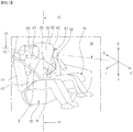
- FIG. 1 is a side view showing a side airbag according to an embodiment.
- FIG. 2 is a side perspective view showing an inflated state of a side airbag according to an embodiment.
- the airbag 1 is installed in a side portion of a seat bag 11 of a vehicle seat 10 toward an inside of a vehicle.
- the seat back 11 of the vehicle seat 10 is connected to a rear end of a seat cushion.
- a head rest 15 is connected to an upper end of the seat back 13.
- the airbag 30 is modularized with an inflator 40 and stored in a side portion of the seat back 11 in a folded state.
- the airbag 30 is inflated by the gas pressure generated from the single inflator 40 to be deployed between two occupants O1 and O2 (see FIG. 2 ) sitting in the width direction of a vehicle.
- the inflator 40 is electrically connected to a control device 51 installed in a vehicle.
- a crash sensor 53 for sensing a side collision of the vehicle is connected to the control device 51.
- the control device 51 operates the inflator 40.
- a free crash sensor for predicting a side collision is electrically connected to the control device 51, if the control device 51 determines the side collision based on the signal from the free crash sensor, the control device 51 may operate the inflator 40.
- the airbag 30 includes a chest protective area A1 for protecting chests T of the occupants O1 and O2, a head protective area A2 for protecting the heads of the occupants O1 and O2, and a support area A3 which makes contact with the head rest 15 to be supported.
- the support area A3 extends rearward of the head protective area A2 to make contact with the head rest 15 when the airbag 30 is inflated.
- the support area A3 has a size enough to cover the head rest 15, so that the support area A3 is sufficiently supported by the head rest 15 to prohibit the head H1 of the occupant 01 who sits near the crushed side of a vehicle from moving rearward of the head protective area A2 while the head H1 of the occupant O1 is rotated by the impact force applied to the occupant O1 when the vehicle collision occurs, thereby preventing the head H1 of the occupant O1 from colliding with the head of a counterparty occupant.
- the airbag 30 is formed of two pieces of polyester-based fabric which overlap each other and of which outer circumferences are sewed onto each other.
- the chest protective area A1, the head protective area A2 and the support area A3 are integrated with one another.
- the chest protective area A1, the head protective area A2 and the support area A3 may be integrally connected to one another through sewing.
- the airbag 30 is stored in a side of the seat back 11 in a folded state.
- the chest protective area A1 is first inflated with the gas generated from the inflator 40 to be deployed forward F of the vehicle. Then, the gas moves upwardly from the chest protective area A1 to be introduced into the head protective area A2 and the support area A3, so that the head protective area A2 and the support area A3 are rapidly inflated.
- the chest protective area A1 of the airbag 30 includes a concave part 33 for receiving the shoulders S and arms A of the occupants O1 and O2.
- the concave part 300 is inclined forward and downwardly of the vehicle substantially corresponding gradients of the shoulders S and arms A of the occupants O1 and O2.
- the concave part 33 may be formed by a seam line 38 having a substantial U-sharped part 38a and a circular-shaped part 38b formed on both ends of the U-sharped part 38a.
- the concave part 33 may be formed by an inner tether connected to both inner side surfaces of the airbag 10.
- the chest protective area A1 is primarily inflated with the gas generated from the single inflator 40 provided in the inner side surface of the seat back 11 to be deployed in the front direction of the vehicle. Then, the gas in the chest protective area A1 rises in an instant, so that the head protective area A2 and the support area A3 are inflated.
- the support area A3 extends rearward from the head protective area A2 to overlap the head rest 15.
- the support area A3 makes contact with the head rest 15 to be supported when the airbag is inflated.
- the support area A3 has a size enough to cover the head rest 15, such that the support area A3 does not depart from the head rest 15 when the occupant O1 collides with the airbag upon a vehicle collision.
- a tether 39 may be provided to reinforce the supporting strength of the airbag 30 when the airbag 30 is inflated.
- One end of the tether 39 is coupled to a portion near the inflator 40 and the opposite end of the tether 39 is connected to the support area A3, so that the support area 30 may be induced to suitably make contact with the head rest 15 when the airbag 30 is inflated.
- the tether 39 may be provided to an inside or outside of the airbag 30.
- the tether 39 When the tether 39 is provided to an outside of the airbag 30, the tether 39 is restricted by a link member which supports the tether 39 to enable the tether 39 to slide on an outer surface of the airbag 30, such that the tether 39 is prevented from interfering with the structures in the vehicle or the occupants when the airbag 30 is inflated.
- FIGS. 1 and 2 show the airbag 30 protecting the chests and heads of occupants O1 and O2.
- the airbag may be configured in various forms.
- the airbag may extend downwardly to protect the pelvis of an occupant.
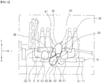
- FIG. 3 is a cross-sectional view taken along line III-III of FIG. 2 .
- FIG. 4 is a longitudinal-sectional view taken along line IV-IV of FIG. 2 .
- the description will be made with regard to the state in which an occupant O1 in a passenger seat (right in the drawings) inertially moves toward an occupant O2 in a driver seat upon a vehicle collision.
- the airbag 30 is deployed between two seats 10 arranged in a width direction of a vehicle when a vehicle collision occurs.
- the airbag 300 may be provided on at least one of the two seats 10.
- the airbag 30, which is inflated and deployed from the inner side surface of the seat back 13 of a left seat 10 based on the front direction F of a vehicle, is depicted.
- the chest protective area A1 of the airbag 10 is first inflated to be deployed in the front direction F of a vehicle and then, the head protective area A2 and the support area A3 are inflated and deployed in sequence.
- the support area A3 of the airbag 30 makes contact with the head rest 15 to be supported.
- the head H2 of an occupant 01 sitting at the crushed side may be rotated clockwise while making contact with the head protective area A2 of the airbag 30, and may move rearward of the head protective area A2.
- the support area A2 is sufficiently supported by the head rest 15 to restrict the head H1 of the occupant 01, so that the head H1 of the occupant O1 is prevented from colliding with the head H2 of a counterparty occupant O2.
- an upper inflation thickness T1 of the airbag 30 in the width direction of a vehicle may be greater than a lower inflation thickness T2 of the airbag 30.
- the upper inflation thickness of the airbag 30 in the width direction of a vehicle may be gradually narrowed from an upper portion to a lower portion.
- the head H1 of the occupant O1 makes contact with the outer surface 36 of the airbag 30 upon a vehicle collision, the head H1 slides downwardly L of the airbag 30 so that the head H1 may be effectively prevented from colliding with the head H1 of the counterparty occupant O2.
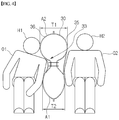
- FIG. 5 is a view showing an uninflated state and a fully inflated state of a side airbag according to an embodiment.
- the airbag 30 is formed to have a pocket shape by sewing outer edges of two sheets of fabric panels 35 and 36 overlapping each other.
- the rear side of the airbag 30 is not sewed to remain in an opened state.
- an inflator connecting part 32 is placed in the seat back 11 of the seat 10 and connected to the inflator 40 (see FIG. 1 ), such that the gas generated from the inflator 40 is supplied into the airbag 30.
- the airbag 30 includes the chest protective area A1, the head protective area A2 and the support area A3 to have a substantial D shape, and the support area A3 protrudes from the head protective area A2.
- FIG. 6 is a cross-sectional view showing an inflated state of a side airbag according to another embodiment.
- an additional chamber area A4 may be formed in the support area A3 of the airbag 30 in order to improve the contact ability with the head rest 15.
- a length of the head rest 15 in the width direction of a vehicle is shorter than that of the back 11 of the seat 10 in the width direction of a vehicle.
- a step difference having a predetermined length G is formed between the seat back 11 and the head rest 15.
- the additional chamber area A4 is inflated corresponding to the step difference between the head rest 15 and the seat back 11, so that the support area A3 is effectively supported by the head rest 15, thereby improving the supporting strength of the airbag 30.
- the inflator 40 is operated by the control device 51.
- the inflator 40 discharges gas into the airbag 30 in which the inflator 40 is stored, the chest protective area A1 of the airbag 30 is inflated to be deployed in the front direction F of the vehicle.
- the gas in the chest protective area A1 rapidly rises into the head protective area A2 and the support area A3, so that the head protective area A2 and the support area A3 are rapidly inflated.
- the airbag 30 When the airbag 30 is inflated, the substantial central portion of the airbag 30 is restricted by the seam line 39 so that the concave part 33 is formed in the chest protective area A1.
- the head H1 of the occupant O1 may substantially crash to the head protective area A2 and may be pushed rearward of the head protective area A2 while being rotated clockwise (arrow C of FIG. 3 ).
- the support area A3 is supported by the head rest 15 of the seat 10 while making contact with the head rest 15, so that the head H1 of the occupant O1 is prohibited from moving toward the head H2 of the counterparty occupant O2, thereby preventing the heads H1 and H2 of the occupants O1 and O2 from colliding with each other.
- the weight of the occupant O1 inertially moved toward the center in the width direction of a vehicle due to the impact of a side collision is applied to the fabric panel 36 of the airbag 30.
- the shoulder S or arm A of the occupant O1 is primarily restricted by the concave part 33 formed in the airbag 30, so that the occupant O1 is prevented from moving.
- the head H1 of the occupant O1 slides downwardly L on the outer surface of the fabric panel 36 of the airbag 30, so that the head H1 of the occupant O1 is prevented from colliding with the head H2 of the counterparty occupant O2.
- the inflation thickness T1 of an upper portion of the airbag 30 in the width direction of the vehicle may be less than the inflation thickness T2 of a lower portion of the airbag 30 in the width direction of the vehicle, so that the airbag 30 may be gradually narrowed from the upper portion of the airbag 30 to the lower portion of the airbag 30, thereby allowing the head H1 of the occupant O1 to smoothly move downwardly.
- the support area A3 When the airbag 30 is inflated, the support area A3 is inflated and deployed in a size enough to cover the head rest 15, such that the support area A3 makes contact with and is supported by the head rest 15. As the result, since the supporting strength of the airbag 30 is excellent, the head H1 of the occupant O1 moves rearward of the head protective area A2, so that the head H1 of the occupant O1 is effectively prevented from colliding with the head H2 of the counterparty occupant O2.
- the tether 39 is provided to a portion near the support area A3 and the inflator 40, when the airbag is inflated, the supporting strength of the airbag 30, specifically, the support area A3 is increased, so that the support area A3 may be suitably supported to the position of the head rest 15.
- the additional inflation area A4 is inflated from both sides of the support area A3, so that the additional inflation area A4 is positioned at the step difference between the back 11 and the head rest 15 of the seat 10.
- the support area A3 of the airbag 30 may more effectively make contact with and supported by the head rest 15, so that the effect of restricting the head H1 of the occupant O1 may be increased.
- the airbag apparatus 1 is provided to a seat (driver or passenger seat) of the first seat row of the vehicle, but the embodiment is not limited thereto.
- the airbag apparatus 1 may be applied to a seat of the second or third seat row of a vehicle.
Abstract
Description
- The embodiment relates to an airbag for side collision, which is deployed between two seats in a width direction of a vehicle upon a vehicle collision.
- Generally, an airbag for side collision for protecting an occupant upon a side collision of a vehicle has been known. The airbag for side collision includes a near side airbag which is inflated to be deployed between an occupant and a component such as a door of a vehicle such that an occupant is protected from the component of a vehicle protruding inwardly due to side collision impact, and a far side airbag which restricts an occupant to move inwardly due to reaction after a side collision.
- Such a far side airbag is required to remain at a predetermined position in an expanded state in order to prevent occupants from colliding with each other, specifically, head-to-head collision.
-
- (Patent document 1) International Publication No.
WO 2009/035114 - (Patent document 2) Japanese Unexamined Patent Publication No.
2015-110373 - It is an object of the disclosure to provide an airbag for side collision capable of preventing the head of an occupant near a crashed side from rotatably moving rearward of a head protective area of the airbag.
- To solve the problem, according to the embodiment, there is provided a side airbag for side collision, which is deployed between two seats in a width direction of a vehicle to prevent occupants siting on the two seats from colliding with each other, which includes: a chest protective area to protect a chest of an occupant; a head protective area extending upward from the chest protective area to protect a head of the occupant; and a support area extending rearward from the head protective area and making contact with a head rest, which is provided on an upper portion of a back of the seat, so as to be supported by the head rest, wherein, the support area of the airbag is supported by the head rest when the vehicle collision occurs to prevent a head of an occupant who sits near a crashed side from moving rearward of the head protective area, thereby preventing the head of the occupant sitting near the crashed side from colliding with a head of a counterparty occupant who faces the occupant sitting near the crashed side in the width direction of the vehicle.
- The chest protective area, the head protective area and the support area are integrally formed, and the side airbag is deployed by a single inflator provided in the back of the seat.
- The support area is larger than an area overlapping the head rest such that the support area is sufficiently supported on the head rest when impact is applied from the occupant.
- A shoulder of the occupant is primarily restricted by a shoulder restricting part formed on the chest protective area when the vehicle collision occurs, and then the head of the occupant near the crashed side slides downwardly along an outer surface of the side airbag.
- The side airbag is configured such that the head of the occupant near the crashed side slides downwardly along an outer surface of the side airbag.
- An inflated thickness of the side airbag in the width direction of the vehicle is gradually narrowed from an upper portion of the side airbag to a lower portion of the side airbag.
- The side airbag further includes a supplementary chamber area provided at a side of the support area facing the head rest and protruding toward the head rest.
- The side airbag further includes a tether including one end connected to the support area and an opposite end connected to a portion near a portion connected to the inflator, wherein the tether reinforces a supporting strength of the side airbag when the side airbag is inflated.
- According to the airbag for side collision of the embodiment, when the air bag is inflated, the support area protruding rearward of the head protective area makes direct contact with the head rest of a vehicle to be supported, so that the head of an occupant who sits near a crashed side may be prevented from rotatably moving rearward of the head protective area of the airbag upon a vehicle collision, thereby preventing a head-to-head collision from occurring between the occupants.
-
-
FIG. 1 is a side view showing a side airbag according to an embodiment. -
FIG. 2 is a side perspective view showing an inflated state of a side airbag according to an embodiment. -
FIG. 3 is a cross-sectional view taken along line III-III ofFIG. 2 . -
FIG. 4 is a longitudinal-sectional view taken along line IV-IV ofFIG. 2 . -
FIG. 5 is a view showing an uninflated state and a fully inflated state of a side airbag according to an embodiment. -
FIG. 6 is a cross-sectional view showing an inflated state of a side airbag according to another embodiment. - Hereinafter, embodiments of the disclosure will be described in more detail with reference to accompanying drawings. The disclosure is not limited to the following embodiments but includes various applications and modifications. The embodiments will make the disclosure of the present invention complete, and allow those skilled in the art to completely comprehend the scope of the disclosure.
- In the drawings, arrow F represents a front direction of a vehicle, arrow U represents an upper direction of a vehicle, and arrow I represents an inside of a vehicle in a width direction of the vehicle. In addition, two occupants are denoted as reference numerals O1 and O2, respectively.
-
FIG. 1 is a side view showing a side airbag according to an embodiment.FIG. 2 is a side perspective view showing an inflated state of a side airbag according to an embodiment. - Referring to
FIGS. 1 and2 , the airbag 1 is installed in a side portion of aseat bag 11 of avehicle seat 10 toward an inside of a vehicle. - The
seat back 11 of thevehicle seat 10 is connected to a rear end of a seat cushion. Ahead rest 15 is connected to an upper end of the seat back 13. - The
airbag 30 is modularized with aninflator 40 and stored in a side portion of the seat back 11 in a folded state. Theairbag 30 is inflated by the gas pressure generated from thesingle inflator 40 to be deployed between two occupants O1 and O2 (seeFIG. 2 ) sitting in the width direction of a vehicle. - The
inflator 40 is electrically connected to acontrol device 51 installed in a vehicle. Acrash sensor 53 for sensing a side collision of the vehicle is connected to thecontrol device 51. When the side collision of the vehicle is sensed based on a signal from thecrash sensor 53, thecontrol device 51 operates theinflator 40. In addition, when a free crash sensor for predicting a side collision is electrically connected to thecontrol device 51, if thecontrol device 51 determines the side collision based on the signal from the free crash sensor, thecontrol device 51 may operate theinflator 40. - The
airbag 30 includes a chest protective area A1 for protecting chests T of the occupants O1 and O2, a head protective area A2 for protecting the heads of the occupants O1 and O2, and a support area A3 which makes contact with thehead rest 15 to be supported. - The support area A3 extends rearward of the head protective area A2 to make contact with the
head rest 15 when theairbag 30 is inflated. The support area A3 has a size enough to cover thehead rest 15, so that the support area A3 is sufficiently supported by thehead rest 15 to prohibit the head H1 of theoccupant 01 who sits near the crushed side of a vehicle from moving rearward of the head protective area A2 while the head H1 of the occupant O1 is rotated by the impact force applied to the occupant O1 when the vehicle collision occurs, thereby preventing the head H1 of the occupant O1 from colliding with the head of a counterparty occupant. - For example, the
airbag 30 is formed of two pieces of polyester-based fabric which overlap each other and of which outer circumferences are sewed onto each other. The chest protective area A1, the head protective area A2 and the support area A3 are integrated with one another. According to another embodiment, after the chest protective area A1, the head protective area A2 and the support area A3 are separately formed, the chest protective area A1, the head protective area A2 and the support area A3 may be integrally connected to one another through sewing. - In this case, the
airbag 30 is stored in a side of the seat back 11 in a folded state. When a vehicle collision occurs, the chest protective area A1 is first inflated with the gas generated from theinflator 40 to be deployed forward F of the vehicle. Then, the gas moves upwardly from the chest protective area A1 to be introduced into the head protective area A2 and the support area A3, so that the head protective area A2 and the support area A3 are rapidly inflated. - The chest protective area A1 of the
airbag 30 includes aconcave part 33 for receiving the shoulders S and arms A of the occupants O1 and O2. The concave part 300 is inclined forward and downwardly of the vehicle substantially corresponding gradients of the shoulders S and arms A of the occupants O1 and O2. - According to one embodiment, the
concave part 33 may be formed by aseam line 38 having a substantial U-sharpedpart 38a and a circular-shaped part 38b formed on both ends of the U-sharpedpart 38a. According to another embodiment, theconcave part 33 may be formed by an inner tether connected to both inner side surfaces of theairbag 10. - In this case, when a vehicle collision occurs, after the shoulder S or arm A of an occupant O1 is primarily restricted in the
concave part 33, the head H1 of the occupant O1 slides downwardly from the head protective area A2 of theairbag 30. - According to the
airbag 30, the chest protective area A1 is primarily inflated with the gas generated from thesingle inflator 40 provided in the inner side surface of theseat back 11 to be deployed in the front direction of the vehicle. Then, the gas in the chest protective area A1 rises in an instant, so that the head protective area A2 and the support area A3 are inflated. - In this case, the support area A3 extends rearward from the head protective area A2 to overlap the
head rest 15. The support area A3 makes contact with thehead rest 15 to be supported when the airbag is inflated. Thus, when a vehicle collision occurs, the head H1 of an occupant O1 is prevented from rotatably moving rearward of the head protective area A2 so that the head H1 of an occupant O1 may not collide with the head H2 of a counterparty occupant O2. - It is preferable that the support area A3 has a size enough to cover the
head rest 15, such that the support area A3 does not depart from thehead rest 15 when the occupant O1 collides with the airbag upon a vehicle collision. - According to an embodiment, a
tether 39 may be provided to reinforce the supporting strength of theairbag 30 when theairbag 30 is inflated. One end of thetether 39 is coupled to a portion near the inflator 40 and the opposite end of thetether 39 is connected to the support area A3, so that thesupport area 30 may be induced to suitably make contact with thehead rest 15 when theairbag 30 is inflated. Thetether 39 may be provided to an inside or outside of theairbag 30. When thetether 39 is provided to an outside of theairbag 30, thetether 39 is restricted by a link member which supports thetether 39 to enable thetether 39 to slide on an outer surface of theairbag 30, such that thetether 39 is prevented from interfering with the structures in the vehicle or the occupants when theairbag 30 is inflated. -
FIGS. 1 and2 show theairbag 30 protecting the chests and heads of occupants O1 and O2. However, the airbag may be configured in various forms. For example, the airbag may extend downwardly to protect the pelvis of an occupant. -
FIG. 3 is a cross-sectional view taken along line III-III ofFIG. 2 .FIG. 4 is a longitudinal-sectional view taken along line IV-IV ofFIG. 2 . Hereinafter, the description will be made with regard to the state in which an occupant O1 in a passenger seat (right in the drawings) inertially moves toward an occupant O2 in a driver seat upon a vehicle collision. - Referring to
FIGS. 3 and4 , theairbag 30 is deployed between twoseats 10 arranged in a width direction of a vehicle when a vehicle collision occurs. The airbag 300 may be provided on at least one of the twoseats 10. In the drawings, theairbag 30, which is inflated and deployed from the inner side surface of the seat back 13 of aleft seat 10 based on the front direction F of a vehicle, is depicted. - In the side portion facing an inside of the vehicle, the chest protective area A1 of the
airbag 10 is first inflated to be deployed in the front direction F of a vehicle and then, the head protective area A2 and the support area A3 are inflated and deployed in sequence. - When the
airbag 30 is inflated, the support area A3 of theairbag 30 makes contact with thehead rest 15 to be supported. When a vehicle collision occurs, the head H2 of anoccupant 01 sitting at the crushed side may be rotated clockwise while making contact with the head protective area A2 of theairbag 30, and may move rearward of the head protective area A2. In this case, the support area A2 is sufficiently supported by thehead rest 15 to restrict the head H1 of theoccupant 01, so that the head H1 of the occupant O1 is prevented from colliding with the head H2 of a counterparty occupant O2. - The head H1 of the occupant O1 restricted by the support area A2 slides downwardly of the vehicle on the
outer surface 36 of theairbag 30. In this case, an upper inflation thickness T1 of theairbag 30 in the width direction of a vehicle may be greater than a lower inflation thickness T2 of theairbag 30. - According another embodiment, the upper inflation thickness of the
airbag 30 in the width direction of a vehicle may be gradually narrowed from an upper portion to a lower portion. - In the configuration described above, when the head H1 of the occupant O1 makes contact with the
outer surface 36 of theairbag 30 upon a vehicle collision, the head H1 slides downwardly L of theairbag 30 so that the head H1 may be effectively prevented from colliding with the head H1 of the counterparty occupant O2. -
FIG. 5 is a view showing an uninflated state and a fully inflated state of a side airbag according to an embodiment. - Referring to
FIG. 5 , theairbag 30 is formed to have a pocket shape by sewing outer edges of two sheets offabric panels - The rear side of the
airbag 30 is not sewed to remain in an opened state. Thus, aninflator connecting part 32 is placed in the seat back 11 of theseat 10 and connected to the inflator 40 (seeFIG. 1 ), such that the gas generated from the inflator 40 is supplied into theairbag 30. - While the two
fabric panels fabric panels seam line 38. When gas is supplied to theairbag 30 through theseam line 38 between thefabric panels airbag 30 is inflated, theconcave part 33 is formed in theinflated airbag 30, so that theconcave part 33 receives the shoulder S or arm A of the occupant O. - The
airbag 30 includes the chest protective area A1, the head protective area A2 and the support area A3 to have a substantial D shape, and the support area A3 protrudes from the head protective area A2. -
FIG. 6 is a cross-sectional view showing an inflated state of a side airbag according to another embodiment. - In the following description, the same elements will be assigned with the same reference numerals, and the repetition in the description of the same elements having the same reference numerals will be omitted.
- Referring to
FIG. 6 , an additional chamber area A4 may be formed in the support area A3 of theairbag 30 in order to improve the contact ability with thehead rest 15. - A length of the
head rest 15 in the width direction of a vehicle is shorter than that of theback 11 of theseat 10 in the width direction of a vehicle. Thus, a step difference having a predetermined length G is formed between the seat back 11 and thehead rest 15. The additional chamber area A4 is inflated corresponding to the step difference between thehead rest 15 and the seat back 11, so that the support area A3 is effectively supported by thehead rest 15, thereby improving the supporting strength of theairbag 30. - Hereinafter, an operation of the airbag according to an embodiment will be described.
- Referring to
FIGS. 1 to 5 , when a vehicle collision occurs and thecontrol device 51 determines the vehicle collision based on the signal from thecrush sensor 53, theinflator 40 is operated by thecontrol device 51. When the inflator 40 discharges gas into theairbag 30 in which theinflator 40 is stored, the chest protective area A1 of theairbag 30 is inflated to be deployed in the front direction F of the vehicle. - Thereafter, the gas in the chest protective area A1 rapidly rises into the head protective area A2 and the support area A3, so that the head protective area A2 and the support area A3 are rapidly inflated.
- When the
airbag 30 is inflated, the substantial central portion of theairbag 30 is restricted by theseam line 39 so that theconcave part 33 is formed in the chest protective area A1. - Thus, while the shoulder S or arm of the occupant O1 moving toward an inside of the vehicle is primarily restricted to the
concave part 33 on thefabric panel 36 of theairbag 30, the head H1 of the occupant O1 slides downwardly on the outer surface of thefabric panel 36 of theairbag 30. - When a vehicle collision occurs, the head H1 of the occupant O1 may substantially crash to the head protective area A2 and may be pushed rearward of the head protective area A2 while being rotated clockwise (arrow C of
FIG. 3 ). In this case, the support area A3 is supported by thehead rest 15 of theseat 10 while making contact with thehead rest 15, so that the head H1 of the occupant O1 is prohibited from moving toward the head H2 of the counterparty occupant O2, thereby preventing the heads H1 and H2 of the occupants O1 and O2 from colliding with each other. - The weight of the occupant O1 inertially moved toward the center in the width direction of a vehicle due to the impact of a side collision is applied to the
fabric panel 36 of theairbag 30. At this time, the shoulder S or arm A of the occupant O1 is primarily restricted by theconcave part 33 formed in theairbag 30, so that the occupant O1 is prevented from moving. - Thus, the head H1 of the occupant O1 slides downwardly L on the outer surface of the
fabric panel 36 of theairbag 30, so that the head H1 of the occupant O1 is prevented from colliding with the head H2 of the counterparty occupant O2. In this case, the inflation thickness T1 of an upper portion of theairbag 30 in the width direction of the vehicle may be less than the inflation thickness T2 of a lower portion of theairbag 30 in the width direction of the vehicle, so that theairbag 30 may be gradually narrowed from the upper portion of theairbag 30 to the lower portion of theairbag 30, thereby allowing the head H1 of the occupant O1 to smoothly move downwardly. - When the
airbag 30 is inflated, the support area A3 is inflated and deployed in a size enough to cover thehead rest 15, such that the support area A3 makes contact with and is supported by thehead rest 15. As the result, since the supporting strength of theairbag 30 is excellent, the head H1 of the occupant O1 moves rearward of the head protective area A2, so that the head H1 of the occupant O1 is effectively prevented from colliding with the head H2 of the counterparty occupant O2. - Since the
tether 39 is provided to a portion near the support area A3 and the inflator 40, when the airbag is inflated, the supporting strength of theairbag 30, specifically, the support area A3 is increased, so that the support area A3 may be suitably supported to the position of thehead rest 15. - Referring to
FIG. 6 together with the above-described operation, the additional inflation area A4 is inflated from both sides of the support area A3, so that the additional inflation area A4 is positioned at the step difference between the back 11 and thehead rest 15 of theseat 10. As the result, the support area A3 of theairbag 30 may more effectively make contact with and supported by thehead rest 15, so that the effect of restricting the head H1 of the occupant O1 may be increased. - In the above-described embodiment, the airbag apparatus 1 is provided to a seat (driver or passenger seat) of the first seat row of the vehicle, but the embodiment is not limited thereto. The airbag apparatus 1 may be applied to a seat of the second or third seat row of a vehicle.
- Although an exemplary embodiment of the disclosure has been described for illustrative purposes, those skilled in the art will appreciate that various modifications, additions and substitutions are possible, without departing from the scope and spirit of the disclosure as disclosed in the accompanying claims.
Claims (8)
- A side airbag for side collision, which is deployed between two seats in a width direction of a vehicle to prevent occupants siting on the two seats from colliding with each other, the side airbag comprising:a chest protective area to protect a chest of an occupant;a head protective area extending upward from the chest protective area to protect a head of the occupant; anda support area extending rearward from the head protective area and making contact with a head rest, which is provided on an upper portion of a back of the seat, so as to be supported by the head rest,wherein, the support area of the airbag is supported by the head rest when the vehicle collision occurs to prevent a head of an occupant who sits near a crashed side from moving rearward of the head protective area, thereby preventing the head of the occupant sitting near the crashed side from colliding with a head of a counterparty occupant who faces the occupant sitting near the crashed side in the width direction of the vehicle.
- The side airbag of claim 1, wherein the chest protective area, the head protective area and the support area are integrally formed, and
the side airbag is deployed by a single inflator provided in the back of the seat. - The side airbag of claim 2, wherein the support area is larger than an area overlapping the head rest such that the support area is sufficiently supported on the head rest when impact is applied from the occupant.
- The side airbag of claim 1, wherein a shoulder of the occupant is primarily restricted by a shoulder restricting part formed on the chest protective area when the vehicle collision occurs, and then the head of the occupant near the crashed side slides downwardly along an outer surface of the side airbag.
- The side airbag of claim 1, wherein the side airbag is configured such that the head of the occupant near the crashed side slides downwardly along an outer surface of the side airbag.
- The side airbag of claim 5, wherein an inflated thickness of the side airbag in the width direction of the vehicle is gradually narrowed from an upper portion of the side airbag to a lower portion of the side airbag.
- The side airbag of claim 1, further comprising a supplementary chamber area provided at a side of the support area facing the head rest and protruding toward the head rest.
- The side airbag of claim 2, further comprising a tether including one end connected to the support area and an opposite end connected to a portion near a portion connected to the inflator, wherein the tether reinforces a supporting strength of the side airbag when the side airbag is inflated.
Applications Claiming Priority (2)
| Application Number | Priority Date | Filing Date | Title |
|---|---|---|---|
| KR1020150162398A KR101739857B1 (en) | 2015-11-19 | 2015-11-19 | Airbag for side impact |
| PCT/KR2016/013257 WO2017086707A1 (en) | 2015-11-19 | 2016-11-17 | Airbag for side collision |
Publications (3)
| Publication Number | Publication Date |
|---|---|
| EP3378709A1 true EP3378709A1 (en) | 2018-09-26 |
| EP3378709A4 EP3378709A4 (en) | 2019-04-03 |
| EP3378709B1 EP3378709B1 (en) | 2021-06-09 |
Family
ID=58719064
Family Applications (1)
| Application Number | Title | Priority Date | Filing Date |
|---|---|---|---|
| EP16866659.2A Active EP3378709B1 (en) | 2015-11-19 | 2016-11-17 | Airbag for side collision |
Country Status (5)
| Country | Link |
|---|---|
| US (1) | US10899305B2 (en) |
| EP (1) | EP3378709B1 (en) |
| JP (1) | JP6756825B2 (en) |
| KR (1) | KR101739857B1 (en) |
| WO (1) | WO2017086707A1 (en) |
Cited By (4)
| Publication number | Priority date | Publication date | Assignee | Title |
|---|---|---|---|---|
| DE102018130029A1 (en) * | 2018-11-28 | 2020-05-28 | Dr. Ing. H.C. F. Porsche Aktiengesellschaft | Airbag device for a side airbag of a vehicle |
| EP3838688A1 (en) * | 2019-12-20 | 2021-06-23 | Autoliv Development AB | Side airbag device |
| CN114802084A (en) * | 2021-01-19 | 2022-07-29 | 丰田自动车株式会社 | Side airbag device for vehicle |
| WO2022223454A1 (en) * | 2021-04-22 | 2022-10-27 | Zf Automotive Germany Gmbh | Central airbag, and vehicle occupant restraint system having a central airbag |
Families Citing this family (10)
| Publication number | Priority date | Publication date | Assignee | Title |
|---|---|---|---|---|
| KR101708213B1 (en) * | 2015-07-22 | 2017-02-20 | 아우토리브 디벨롭먼트 아베 | Airbag for side collision |
| US10773678B2 (en) | 2018-08-21 | 2020-09-15 | Honda Motor Co., Ltd. | Side impact occupant restraint airbag module |
| CN111976644B (en) * | 2019-05-21 | 2022-10-14 | 奥托立夫开发公司 | Airbag device |
| CN111660982A (en) * | 2019-12-05 | 2020-09-15 | 摩登汽车有限公司 | Automobile |
| JP2021098495A (en) * | 2019-12-20 | 2021-07-01 | オートリブ ディベロップメント エービー | Side airbag device |
| JP2021130377A (en) * | 2020-02-19 | 2021-09-09 | 本田技研工業株式会社 | Vehicular side airbag device |
| KR20210110474A (en) * | 2020-02-28 | 2021-09-08 | 현대자동차주식회사 | Center side airbag for vehicle |
| KR102543716B1 (en) * | 2021-04-07 | 2023-06-16 | 아우토리브 디벨롭먼트 아베 | Side airbag apparatus for vehicle |
| US11628795B1 (en) | 2022-05-12 | 2023-04-18 | Ford Global Technologies, Llc | Middle console airbag |
| CN115056742B (en) * | 2022-07-28 | 2023-10-31 | 奇瑞汽车股份有限公司 | Roof airbag structure |
Family Cites Families (20)
| Publication number | Priority date | Publication date | Assignee | Title |
|---|---|---|---|---|
| US5556128A (en) * | 1994-11-24 | 1996-09-17 | Volkswagen Ag | Safety arrangement for a vehicle occupant |
| GB2322338B (en) * | 1997-02-20 | 2001-03-14 | Autoliv Dev | Improvements in or relating to an air-bag arrangement |
| JP5382584B2 (en) | 2007-09-14 | 2014-01-08 | トヨタ自動車東日本株式会社 | Airbag device |
| US8702122B2 (en) * | 2007-09-16 | 2014-04-22 | Toyota Motor East Japan, Inc. | Airbag |
| JP5131658B2 (en) * | 2007-09-16 | 2013-01-30 | トヨタ自動車東日本株式会社 | Airbag |
| DE102007056848B4 (en) * | 2007-11-26 | 2018-10-11 | GM Global Technology Operations LLC (n. d. Ges. d. Staates Delaware) | Side airbag system, backrest and headrest |
| US8388019B2 (en) * | 2009-09-29 | 2013-03-05 | Tk Holdings Inc. | Airbag module |
| KR20120051279A (en) | 2010-11-12 | 2012-05-22 | 현대자동차주식회사 | Center airbag module in vehicle |
| KR101292323B1 (en) * | 2011-07-12 | 2013-07-31 | 아우토리브 디벨롭먼트 아베 | Side airbag module for vehicle seat |
| US20130079208A1 (en) * | 2011-09-26 | 2013-03-28 | GM Global Technology Operations LLC | Method for folding airbag cushion |
| DE102012008390A1 (en) * | 2012-04-26 | 2013-10-31 | Trw Automotive Gmbh | Vehicle occupant protection system |
| JP5918621B2 (en) * | 2012-05-09 | 2016-05-18 | 芦森工業株式会社 | Side airbag device |
| JP5594327B2 (en) * | 2012-07-10 | 2014-09-24 | トヨタ自動車株式会社 | Vehicle seat |
| JP2014076702A (en) * | 2012-10-09 | 2014-05-01 | Toyota Motor Corp | Occupant protection device for vehicle |
| JP5754436B2 (en) * | 2012-12-03 | 2015-07-29 | トヨタ自動車株式会社 | Vehicle occupant restraint system |
| JP5949737B2 (en) | 2013-12-06 | 2016-07-13 | トヨタ自動車株式会社 | Far-side airbag device for vehicles |
| JP5949791B2 (en) * | 2014-01-14 | 2016-07-13 | トヨタ自動車株式会社 | Vehicle occupant protection device |
| JP5879380B2 (en) * | 2014-03-28 | 2016-03-08 | 富士重工業株式会社 | Airbag device |
| JP5895014B2 (en) | 2014-03-28 | 2016-03-30 | 富士重工業株式会社 | Airbag device |
| JP5914556B2 (en) * | 2014-03-28 | 2016-05-11 | 富士重工業株式会社 | Airbag device |
-
2015
- 2015-11-19 KR KR1020150162398A patent/KR101739857B1/en active IP Right Grant
-
2016
- 2016-11-17 US US15/776,230 patent/US10899305B2/en active Active
- 2016-11-17 WO PCT/KR2016/013257 patent/WO2017086707A1/en active Application Filing
- 2016-11-17 EP EP16866659.2A patent/EP3378709B1/en active Active
- 2016-11-17 JP JP2018523751A patent/JP6756825B2/en active Active
Cited By (4)
| Publication number | Priority date | Publication date | Assignee | Title |
|---|---|---|---|---|
| DE102018130029A1 (en) * | 2018-11-28 | 2020-05-28 | Dr. Ing. H.C. F. Porsche Aktiengesellschaft | Airbag device for a side airbag of a vehicle |
| EP3838688A1 (en) * | 2019-12-20 | 2021-06-23 | Autoliv Development AB | Side airbag device |
| CN114802084A (en) * | 2021-01-19 | 2022-07-29 | 丰田自动车株式会社 | Side airbag device for vehicle |
| WO2022223454A1 (en) * | 2021-04-22 | 2022-10-27 | Zf Automotive Germany Gmbh | Central airbag, and vehicle occupant restraint system having a central airbag |
Also Published As
| Publication number | Publication date |
|---|---|
| US10899305B2 (en) | 2021-01-26 |
| JP6756825B2 (en) | 2020-09-16 |
| JP2018535883A (en) | 2018-12-06 |
| WO2017086707A1 (en) | 2017-05-26 |
| KR101739857B1 (en) | 2017-05-25 |
| EP3378709A4 (en) | 2019-04-03 |
| EP3378709B1 (en) | 2021-06-09 |
| US20200254961A1 (en) | 2020-08-13 |
Similar Documents
| Publication | Publication Date | Title |
|---|---|---|
| EP3378709B1 (en) | Airbag for side collision | |
| KR101708213B1 (en) | Airbag for side collision | |
| JP6907103B2 (en) | Vehicle airbags | |
| CN107415886B (en) | Occupant protection device | |
| JP6107757B2 (en) | Passenger airbag device | |
| JP6411971B2 (en) | Crew protection device | |
| JP6428929B2 (en) | Crew protection device | |
| US9296357B2 (en) | Vehicle far-side airbag apparatus | |
| US9403500B2 (en) | Airbag device | |
| JP2008201175A (en) | Side airbag device | |
| US11752966B2 (en) | Side airbag device | |
| US9469267B2 (en) | Airbag device | |
| JP6940629B2 (en) | Side airbag device and vehicle seat equipped with it | |
| US10155495B2 (en) | Side and seat-back airbag | |
| CN114763120A (en) | Occupant restraint system | |
| JP6613855B2 (en) | Rear seat occupant protection airbag device for vehicle | |
| JP6517662B2 (en) | Occupant protection device | |
| JP6350423B2 (en) | Crew protection device | |
| JP6287706B2 (en) | Vehicle occupant protection device | |
| JP2010247661A (en) | Occupant safety device | |
| JP5672222B2 (en) | Vehicle occupant restraint system | |
| CN110871765B (en) | Airbag device | |
| EP4368459A1 (en) | Airbag device |
Legal Events
| Date | Code | Title | Description |
|---|---|---|---|
| STAA | Information on the status of an ep patent application or granted ep patent |
Free format text: STATUS: THE INTERNATIONAL PUBLICATION HAS BEEN MADE |
|
| PUAI | Public reference made under article 153(3) epc to a published international application that has entered the european phase |
Free format text: ORIGINAL CODE: 0009012 |
|
| STAA | Information on the status of an ep patent application or granted ep patent |
Free format text: STATUS: REQUEST FOR EXAMINATION WAS MADE |
|
| 17P | Request for examination filed |
Effective date: 20180504 |
|
| AK | Designated contracting states |
Kind code of ref document: A1 Designated state(s): AL AT BE BG CH CY CZ DE DK EE ES FI FR GB GR HR HU IE IS IT LI LT LU LV MC MK MT NL NO PL PT RO RS SE SI SK SM TR |
|
| AX | Request for extension of the european patent |
Extension state: BA ME |
|
| DAV | Request for validation of the european patent (deleted) | ||
| DAX | Request for extension of the european patent (deleted) | ||
| A4 | Supplementary search report drawn up and despatched |
Effective date: 20190304 |
|
| RIC1 | Information provided on ipc code assigned before grant |
Ipc: B60R 21/231 20110101ALI20190226BHEP Ipc: B60R 21/2334 20110101ALI20190226BHEP Ipc: B60R 21/2338 20110101ALI20190226BHEP Ipc: B60R 21/207 20060101AFI20190226BHEP |
|
| GRAP | Despatch of communication of intention to grant a patent |
Free format text: ORIGINAL CODE: EPIDOSNIGR1 |
|
| STAA | Information on the status of an ep patent application or granted ep patent |
Free format text: STATUS: GRANT OF PATENT IS INTENDED |
|
| INTG | Intention to grant announced |
Effective date: 20210316 |
|
| GRAS | Grant fee paid |
Free format text: ORIGINAL CODE: EPIDOSNIGR3 |
|
| GRAA | (expected) grant |
Free format text: ORIGINAL CODE: 0009210 |
|
| STAA | Information on the status of an ep patent application or granted ep patent |
Free format text: STATUS: THE PATENT HAS BEEN GRANTED |
|
| AK | Designated contracting states |
Kind code of ref document: B1 Designated state(s): AL AT BE BG CH CY CZ DE DK EE ES FI FR GB GR HR HU IE IS IT LI LT LU LV MC MK MT NL NO PL PT RO RS SE SI SK SM TR |
|
| REG | Reference to a national code |
Ref country code: GB Ref legal event code: FG4D |
|
| REG | Reference to a national code |
Ref country code: CH Ref legal event code: EP Ref country code: AT Ref legal event code: REF Ref document number: 1400211 Country of ref document: AT Kind code of ref document: T Effective date: 20210615 |
|
| REG | Reference to a national code |
Ref country code: DE Ref legal event code: R096 Ref document number: 602016059230 Country of ref document: DE |
|
| REG | Reference to a national code |
Ref country code: IE Ref legal event code: FG4D |
|
| REG | Reference to a national code |
Ref country code: LT Ref legal event code: MG9D |
|
| PG25 | Lapsed in a contracting state [announced via postgrant information from national office to epo] |
Ref country code: FI Free format text: LAPSE BECAUSE OF FAILURE TO SUBMIT A TRANSLATION OF THE DESCRIPTION OR TO PAY THE FEE WITHIN THE PRESCRIBED TIME-LIMIT Effective date: 20210609 Ref country code: LT Free format text: LAPSE BECAUSE OF FAILURE TO SUBMIT A TRANSLATION OF THE DESCRIPTION OR TO PAY THE FEE WITHIN THE PRESCRIBED TIME-LIMIT Effective date: 20210609 Ref country code: BG Free format text: LAPSE BECAUSE OF FAILURE TO SUBMIT A TRANSLATION OF THE DESCRIPTION OR TO PAY THE FEE WITHIN THE PRESCRIBED TIME-LIMIT Effective date: 20210909 Ref country code: HR Free format text: LAPSE BECAUSE OF FAILURE TO SUBMIT A TRANSLATION OF THE DESCRIPTION OR TO PAY THE FEE WITHIN THE PRESCRIBED TIME-LIMIT Effective date: 20210609 |
|
| REG | Reference to a national code |
Ref country code: AT Ref legal event code: MK05 Ref document number: 1400211 Country of ref document: AT Kind code of ref document: T Effective date: 20210609 |
|
| REG | Reference to a national code |
Ref country code: NL Ref legal event code: MP Effective date: 20210609 |
|
| PG25 | Lapsed in a contracting state [announced via postgrant information from national office to epo] |
Ref country code: SE Free format text: LAPSE BECAUSE OF FAILURE TO SUBMIT A TRANSLATION OF THE DESCRIPTION OR TO PAY THE FEE WITHIN THE PRESCRIBED TIME-LIMIT Effective date: 20210609 Ref country code: RS Free format text: LAPSE BECAUSE OF FAILURE TO SUBMIT A TRANSLATION OF THE DESCRIPTION OR TO PAY THE FEE WITHIN THE PRESCRIBED TIME-LIMIT Effective date: 20210609 Ref country code: NO Free format text: LAPSE BECAUSE OF FAILURE TO SUBMIT A TRANSLATION OF THE DESCRIPTION OR TO PAY THE FEE WITHIN THE PRESCRIBED TIME-LIMIT Effective date: 20210909 Ref country code: GR Free format text: LAPSE BECAUSE OF FAILURE TO SUBMIT A TRANSLATION OF THE DESCRIPTION OR TO PAY THE FEE WITHIN THE PRESCRIBED TIME-LIMIT Effective date: 20210910 Ref country code: LV Free format text: LAPSE BECAUSE OF FAILURE TO SUBMIT A TRANSLATION OF THE DESCRIPTION OR TO PAY THE FEE WITHIN THE PRESCRIBED TIME-LIMIT Effective date: 20210609 |
|
| PG25 | Lapsed in a contracting state [announced via postgrant information from national office to epo] |
Ref country code: RO Free format text: LAPSE BECAUSE OF FAILURE TO SUBMIT A TRANSLATION OF THE DESCRIPTION OR TO PAY THE FEE WITHIN THE PRESCRIBED TIME-LIMIT Effective date: 20210609 Ref country code: PT Free format text: LAPSE BECAUSE OF FAILURE TO SUBMIT A TRANSLATION OF THE DESCRIPTION OR TO PAY THE FEE WITHIN THE PRESCRIBED TIME-LIMIT Effective date: 20211011 Ref country code: NL Free format text: LAPSE BECAUSE OF FAILURE TO SUBMIT A TRANSLATION OF THE DESCRIPTION OR TO PAY THE FEE WITHIN THE PRESCRIBED TIME-LIMIT Effective date: 20210609 Ref country code: ES Free format text: LAPSE BECAUSE OF FAILURE TO SUBMIT A TRANSLATION OF THE DESCRIPTION OR TO PAY THE FEE WITHIN THE PRESCRIBED TIME-LIMIT Effective date: 20210609 Ref country code: EE Free format text: LAPSE BECAUSE OF FAILURE TO SUBMIT A TRANSLATION OF THE DESCRIPTION OR TO PAY THE FEE WITHIN THE PRESCRIBED TIME-LIMIT Effective date: 20210609 Ref country code: CZ Free format text: LAPSE BECAUSE OF FAILURE TO SUBMIT A TRANSLATION OF THE DESCRIPTION OR TO PAY THE FEE WITHIN THE PRESCRIBED TIME-LIMIT Effective date: 20210609 Ref country code: AT Free format text: LAPSE BECAUSE OF FAILURE TO SUBMIT A TRANSLATION OF THE DESCRIPTION OR TO PAY THE FEE WITHIN THE PRESCRIBED TIME-LIMIT Effective date: 20210609 Ref country code: SM Free format text: LAPSE BECAUSE OF FAILURE TO SUBMIT A TRANSLATION OF THE DESCRIPTION OR TO PAY THE FEE WITHIN THE PRESCRIBED TIME-LIMIT Effective date: 20210609 Ref country code: SK Free format text: LAPSE BECAUSE OF FAILURE TO SUBMIT A TRANSLATION OF THE DESCRIPTION OR TO PAY THE FEE WITHIN THE PRESCRIBED TIME-LIMIT Effective date: 20210609 |
|
| PG25 | Lapsed in a contracting state [announced via postgrant information from national office to epo] |
Ref country code: PL Free format text: LAPSE BECAUSE OF FAILURE TO SUBMIT A TRANSLATION OF THE DESCRIPTION OR TO PAY THE FEE WITHIN THE PRESCRIBED TIME-LIMIT Effective date: 20210609 |
|
| REG | Reference to a national code |
Ref country code: DE Ref legal event code: R097 Ref document number: 602016059230 Country of ref document: DE |
|
| PLBE | No opposition filed within time limit |
Free format text: ORIGINAL CODE: 0009261 |
|
| STAA | Information on the status of an ep patent application or granted ep patent |
Free format text: STATUS: NO OPPOSITION FILED WITHIN TIME LIMIT |
|
| PG25 | Lapsed in a contracting state [announced via postgrant information from national office to epo] |
Ref country code: DK Free format text: LAPSE BECAUSE OF FAILURE TO SUBMIT A TRANSLATION OF THE DESCRIPTION OR TO PAY THE FEE WITHIN THE PRESCRIBED TIME-LIMIT Effective date: 20210609 |
|
| 26N | No opposition filed |
Effective date: 20220310 |
|
| PG25 | Lapsed in a contracting state [announced via postgrant information from national office to epo] |
Ref country code: AL Free format text: LAPSE BECAUSE OF FAILURE TO SUBMIT A TRANSLATION OF THE DESCRIPTION OR TO PAY THE FEE WITHIN THE PRESCRIBED TIME-LIMIT Effective date: 20210609 |
|
| PG25 | Lapsed in a contracting state [announced via postgrant information from national office to epo] |
Ref country code: MC Free format text: LAPSE BECAUSE OF FAILURE TO SUBMIT A TRANSLATION OF THE DESCRIPTION OR TO PAY THE FEE WITHIN THE PRESCRIBED TIME-LIMIT Effective date: 20210609 |
|
| REG | Reference to a national code |
Ref country code: CH Ref legal event code: PL |
|
| PG25 | Lapsed in a contracting state [announced via postgrant information from national office to epo] |
Ref country code: LU Free format text: LAPSE BECAUSE OF NON-PAYMENT OF DUE FEES Effective date: 20211117 Ref country code: IT Free format text: LAPSE BECAUSE OF FAILURE TO SUBMIT A TRANSLATION OF THE DESCRIPTION OR TO PAY THE FEE WITHIN THE PRESCRIBED TIME-LIMIT Effective date: 20210609 Ref country code: BE Free format text: LAPSE BECAUSE OF NON-PAYMENT OF DUE FEES Effective date: 20211130 |
|
| REG | Reference to a national code |
Ref country code: BE Ref legal event code: MM Effective date: 20211130 |
|
| PG25 | Lapsed in a contracting state [announced via postgrant information from national office to epo] |
Ref country code: IE Free format text: LAPSE BECAUSE OF NON-PAYMENT OF DUE FEES Effective date: 20211117 |
|
| PG25 | Lapsed in a contracting state [announced via postgrant information from national office to epo] |
Ref country code: HU Free format text: LAPSE BECAUSE OF FAILURE TO SUBMIT A TRANSLATION OF THE DESCRIPTION OR TO PAY THE FEE WITHIN THE PRESCRIBED TIME-LIMIT; INVALID AB INITIO Effective date: 20161117 |
|
| P01 | Opt-out of the competence of the unified patent court (upc) registered |
Effective date: 20230507 |
|
| PG25 | Lapsed in a contracting state [announced via postgrant information from national office to epo] |
Ref country code: CY Free format text: LAPSE BECAUSE OF FAILURE TO SUBMIT A TRANSLATION OF THE DESCRIPTION OR TO PAY THE FEE WITHIN THE PRESCRIBED TIME-LIMIT Effective date: 20210609 |
|
| PG25 | Lapsed in a contracting state [announced via postgrant information from national office to epo] |
Ref country code: LI Free format text: LAPSE BECAUSE OF NON-PAYMENT OF DUE FEES Effective date: 20220701 Ref country code: CH Free format text: LAPSE BECAUSE OF NON-PAYMENT OF DUE FEES Effective date: 20220701 |
|
| PGFP | Annual fee paid to national office [announced via postgrant information from national office to epo] |
Ref country code: GB Payment date: 20231121 Year of fee payment: 8 |
|
| PGFP | Annual fee paid to national office [announced via postgrant information from national office to epo] |
Ref country code: FR Payment date: 20231123 Year of fee payment: 8 Ref country code: DE Payment date: 20231127 Year of fee payment: 8 |
|
| PG25 | Lapsed in a contracting state [announced via postgrant information from national office to epo] |
Ref country code: MK Free format text: LAPSE BECAUSE OF FAILURE TO SUBMIT A TRANSLATION OF THE DESCRIPTION OR TO PAY THE FEE WITHIN THE PRESCRIBED TIME-LIMIT Effective date: 20210609 |