EP4368459A1 - Airbag device - Google Patents
Airbag device Download PDFInfo
- Publication number
- EP4368459A1 EP4368459A1 EP22837435.1A EP22837435A EP4368459A1 EP 4368459 A1 EP4368459 A1 EP 4368459A1 EP 22837435 A EP22837435 A EP 22837435A EP 4368459 A1 EP4368459 A1 EP 4368459A1
- Authority
- EP
- European Patent Office
- Prior art keywords
- chamber
- occupant
- airbag device
- airbag
- base fabric
- Prior art date
- Legal status (The legal status is an assumption and is not a legal conclusion. Google has not performed a legal analysis and makes no representation as to the accuracy of the status listed.)
- Pending
Links
- 239000004744 fabric Substances 0.000 claims description 32
- JOYRKODLDBILNP-UHFFFAOYSA-N Ethyl urethane Chemical compound CCOC(N)=O JOYRKODLDBILNP-UHFFFAOYSA-N 0.000 description 2
- 239000010985 leather Substances 0.000 description 2
- 238000010586 diagram Methods 0.000 description 1
- 239000012530 fluid Substances 0.000 description 1
- 239000006261 foam material Substances 0.000 description 1
- 238000005187 foaming Methods 0.000 description 1
- 230000002452 interceptive effect Effects 0.000 description 1
- 239000000463 material Substances 0.000 description 1
- 238000012986 modification Methods 0.000 description 1
- 230000004048 modification Effects 0.000 description 1
Images


Classifications
-
- B—PERFORMING OPERATIONS; TRANSPORTING
- B60—VEHICLES IN GENERAL
- B60R—VEHICLES, VEHICLE FITTINGS, OR VEHICLE PARTS, NOT OTHERWISE PROVIDED FOR
- B60R21/00—Arrangements or fittings on vehicles for protecting or preventing injuries to occupants or pedestrians in case of accidents or other traffic risks
- B60R21/02—Occupant safety arrangements or fittings, e.g. crash pads
- B60R21/16—Inflatable occupant restraints or confinements designed to inflate upon impact or impending impact, e.g. air bags
- B60R21/20—Arrangements for storing inflatable members in their non-use or deflated condition; Arrangement or mounting of air bag modules or components
- B60R21/207—Arrangements for storing inflatable members in their non-use or deflated condition; Arrangement or mounting of air bag modules or components in vehicle seats
-
- B—PERFORMING OPERATIONS; TRANSPORTING
- B60—VEHICLES IN GENERAL
- B60N—SEATS SPECIALLY ADAPTED FOR VEHICLES; VEHICLE PASSENGER ACCOMMODATION NOT OTHERWISE PROVIDED FOR
- B60N2/00—Seats specially adapted for vehicles; Arrangement or mounting of seats in vehicles
- B60N2/24—Seats specially adapted for vehicles; Arrangement or mounting of seats in vehicles for particular purposes or particular vehicles
- B60N2/42—Seats specially adapted for vehicles; Arrangement or mounting of seats in vehicles for particular purposes or particular vehicles the seat constructed to protect the occupant from the effect of abnormal g-forces, e.g. crash or safety seats
- B60N2/427—Seats or parts thereof displaced during a crash
-
- B—PERFORMING OPERATIONS; TRANSPORTING
- B60—VEHICLES IN GENERAL
- B60R—VEHICLES, VEHICLE FITTINGS, OR VEHICLE PARTS, NOT OTHERWISE PROVIDED FOR
- B60R21/00—Arrangements or fittings on vehicles for protecting or preventing injuries to occupants or pedestrians in case of accidents or other traffic risks
- B60R21/02—Occupant safety arrangements or fittings, e.g. crash pads
- B60R21/16—Inflatable occupant restraints or confinements designed to inflate upon impact or impending impact, e.g. air bags
- B60R21/23—Inflatable members
- B60R21/231—Inflatable members characterised by their shape, construction or spatial configuration
- B60R21/233—Inflatable members characterised by their shape, construction or spatial configuration comprising a plurality of individual compartments; comprising two or more bag-like members, one within the other
-
- B—PERFORMING OPERATIONS; TRANSPORTING
- B60—VEHICLES IN GENERAL
- B60R—VEHICLES, VEHICLE FITTINGS, OR VEHICLE PARTS, NOT OTHERWISE PROVIDED FOR
- B60R21/00—Arrangements or fittings on vehicles for protecting or preventing injuries to occupants or pedestrians in case of accidents or other traffic risks
- B60R21/02—Occupant safety arrangements or fittings, e.g. crash pads
- B60R21/16—Inflatable occupant restraints or confinements designed to inflate upon impact or impending impact, e.g. air bags
- B60R21/23—Inflatable members
- B60R21/231—Inflatable members characterised by their shape, construction or spatial configuration
- B60R21/2334—Expansion control features
- B60R21/2338—Tethers
-
- B—PERFORMING OPERATIONS; TRANSPORTING
- B60—VEHICLES IN GENERAL
- B60R—VEHICLES, VEHICLE FITTINGS, OR VEHICLE PARTS, NOT OTHERWISE PROVIDED FOR
- B60R21/00—Arrangements or fittings on vehicles for protecting or preventing injuries to occupants or pedestrians in case of accidents or other traffic risks
- B60R2021/003—Arrangements or fittings on vehicles for protecting or preventing injuries to occupants or pedestrians in case of accidents or other traffic risks characterised by occupant or pedestian
- B60R2021/0039—Body parts of the occupant or pedestrian affected by the accident
- B60R2021/0048—Head
-
- B—PERFORMING OPERATIONS; TRANSPORTING
- B60—VEHICLES IN GENERAL
- B60R—VEHICLES, VEHICLE FITTINGS, OR VEHICLE PARTS, NOT OTHERWISE PROVIDED FOR
- B60R21/00—Arrangements or fittings on vehicles for protecting or preventing injuries to occupants or pedestrians in case of accidents or other traffic risks
- B60R21/02—Occupant safety arrangements or fittings, e.g. crash pads
- B60R21/16—Inflatable occupant restraints or confinements designed to inflate upon impact or impending impact, e.g. air bags
- B60R21/23—Inflatable members
- B60R21/231—Inflatable members characterised by their shape, construction or spatial configuration
- B60R21/233—Inflatable members characterised by their shape, construction or spatial configuration comprising a plurality of individual compartments; comprising two or more bag-like members, one within the other
- B60R2021/23308—Inflatable members characterised by their shape, construction or spatial configuration comprising a plurality of individual compartments; comprising two or more bag-like members, one within the other the individual compartments defining the external shape of the bag
-
- B—PERFORMING OPERATIONS; TRANSPORTING
- B60—VEHICLES IN GENERAL
- B60R—VEHICLES, VEHICLE FITTINGS, OR VEHICLE PARTS, NOT OTHERWISE PROVIDED FOR
- B60R21/00—Arrangements or fittings on vehicles for protecting or preventing injuries to occupants or pedestrians in case of accidents or other traffic risks
- B60R21/02—Occupant safety arrangements or fittings, e.g. crash pads
- B60R21/16—Inflatable occupant restraints or confinements designed to inflate upon impact or impending impact, e.g. air bags
- B60R21/23—Inflatable members
- B60R21/231—Inflatable members characterised by their shape, construction or spatial configuration
- B60R21/233—Inflatable members characterised by their shape, construction or spatial configuration comprising a plurality of individual compartments; comprising two or more bag-like members, one within the other
- B60R2021/23324—Inner walls crating separate compartments, e.g. communicating with vents
-
- B—PERFORMING OPERATIONS; TRANSPORTING
- B60—VEHICLES IN GENERAL
- B60R—VEHICLES, VEHICLE FITTINGS, OR VEHICLE PARTS, NOT OTHERWISE PROVIDED FOR
- B60R21/00—Arrangements or fittings on vehicles for protecting or preventing injuries to occupants or pedestrians in case of accidents or other traffic risks
- B60R21/02—Occupant safety arrangements or fittings, e.g. crash pads
- B60R21/16—Inflatable occupant restraints or confinements designed to inflate upon impact or impending impact, e.g. air bags
- B60R21/23—Inflatable members
- B60R21/231—Inflatable members characterised by their shape, construction or spatial configuration
- B60R21/2334—Expansion control features
- B60R21/2338—Tethers
- B60R2021/23386—External tether means
Definitions
- the present invention relates to an airbag device equipped in a vehicle seat, and particularly relates to an airbag device that can appropriately protect the head of an occupant.
- Providing a vehicle with one or a plurality of airbag devices in order to protect an occupant therein in the event of a vehicle accident is well known.
- airbag devices such as so-called driver airbag devices that deploy from near the center of a steering wheel to protect a driver, curtain airbags that deploy downward inside a window to protect an occupant in the event of a lateral impact, rollover, or overturning accident, side airbag devices that are deployed to a side of an occupant (side of a seat) to protect the occupant in the event of a lateral impact of the vehicle, and the like.
- the present invention relates to a novel side airbag device provided in a vehicle seat.
- Patent Document 1 can restrain one side of an occupant's head (either left or right side) with a deployed airbag, but it is virtually impossible for such devices to protect an entire area including the front of the head.
- Patent Document 1 Japanese Unexamined Patent Application Publication 2019-137307
- an object of the present invention is to provide a revolutionary airbag device that can protect an occupant's head from one side, to the front, to the other side.
- the present invention is an airbag device stored in a vehicle seat, the airbag device including: an inflator for generating expansion gas; and an airbag for deploying from near an upper end of the vehicle seat to protect the periphery of the head of an occupant.
- the airbag includes: a first chamber for protecting one side of an occupant; a second chamber connected to the first chamber and for protecting the front of the occupant's head; a third chamber connected to the second chamber and for deploying from the front of the occupant's head across to the other side of the occupant; and a fourth chamber connected to the third chamber and for deploying at the other side of the occupant.
- the airbag surrounds the occupant's head from one side, the front, and to the other side, such that the occupant's head can be securely restrained regardless of the seat position, reclining angle, and the like.
- the present invention does not require the steering wheel, instrument panel, or the like to be used as a reaction surface when the airbag deploys, and the deployment behavior and shape of the airbag can be stabilized without depending on the seat position or the like.
- the first chamber and the second chamber can be formed integrally by adhering two pieces of base fabric together.
- a bent part can be formed near the boundary between the first chamber and the second chamber, which bends in a direction closer to the occupant's head. Thereby, the second chamber is reliably deployed in front of the occupant's head.
- At least the second chamber can be connected to a tether, and the tension of the tether can form the bent part when the airbag is deployed.
- the first chamber and second chamber can be formed as separate chambers.
- Each of the first chamber and second chamber can be formed by adhering two pieces of base fabrics together. Furthermore, a vicinity of a front end of an inner panel facing an occupant of the base fabric forming the first chamber can be connected to a vicinity of an end part of an inner panel facing the occupant of the base fabric forming the second chamber on the opposite side from the third chamber.
- connection portion By connecting the inner panels of the base fabric, when the airbag is deployed, the connection portion can be restricted from spreading in an outer direction (away from the occupant's head), thereby facilitating the creation of a curved shape so as to surround the head of the occupant.
- the third chamber can be formed by adhering at least two pieces of base fabrics together. Furthermore, an end part of an inner panel facing the occupant of the base fabric forming the second chamber can be connected to an end part of an inner panel facing the occupant of the base fabric forming the third chamber.
- a first vent hole can be formed at a connection part between the second chamber and third chamber.
- the fourth chamber can be formed by folding one piece of base fabric or adhering two pieces of base fabric together.
- a second vent hole can be formed at a connection portion between the third chamber and fourth chamber.
- the first chamber can include an upper direction part for first deploying upward and a front direction part connected to the upper direction part and for deploying toward the front.
- a side protection chamber which is connected near a lower end of the upper direction part of the first chamber and protects the side of the body of the occupant, can be further provided.
- the inflator can be disposed inside the side protection chamber. Furthermore, the configuration can be such that the expansion gas flows from the side protection chamber to the first chamber, second chamber, third chamber, and fourth chamber.
- the second chamber can be extend downward from the first chamber, and can be configured such that an end part of the second chamber that is connected to the third chamber bends upward during deployment of the airbag.
- a side airbag device for protecting a side of the occupant can be provided separately from the airbag device on an opposite side of the vehicle seat with respect to the side where the airbag device is stored.
- the side airbag device is disposed on the so-called near side, and the airbag device for mainly protecting the head is disposed on the far side, such that the occupant can be fully protected.
- the airbag device when an occupant is seated in a seat in a normal posture, the direction the occupant faces is referred to as the "front”, the opposite direction is referred to as the "back”, and the direction indicating the coordinate axis is referred to as the "front-to-back direction”. Moreover, when the passenger is seated in the seat in a regular posture, the right of the passenger is referred to as the "right direction”, the left of the passenger is referred to as the "left direction”, and the direction indicating the coordinate axis is referred to as the "left and right direction”.
- a head direction of the occupant is referred to as "up”
- a waist direction of the occupant is referred to as “down”
- a direction indicating the coordinate axis is referred to as an "up-down direction”.
- the side of a deployed airbag facing the occupant (head) is referred to as the inner side and the opposite side is referred to as the outer side.
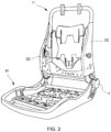
- FIG. 1 is a perspective view mainly illustrating the external shape of a vehicle seat used for a passenger protection apparatus according to the present invention, with an illustration of the airbag device (20) omitted.
- FIG. 2 is a perspective view illustrating an internal structure (seat frame) functioning as a framework of the vehicle seat illustrated in FIG. 1 , with an illustration of the airbag device (20) also omitted herein.
- FIG. 3 is a schematic side surface view of the occupant protection device according to the present invention, and depicts a condition in which the airbag device 20 stored therein on a side surface (far side) of the vehicle seat near a door is observed from the outer side in the vehicle width direction.
- the vehicle seat to which the present invention can be applied includes: a seat cushion 2 of a portion on which an occupant is seated; a seatback 1 forming a backrest; and a headrest 3 connected to an upper end of the seatback 1.
- the airbag device 20 As depicted in FIG. 1 , the airbag device 20 according to the present example is stored in a side support part (far side) of the vehicle seat.
- Code 21 represents a housing for storing one part (head protection part 31) of an airbag configuring the airbag device 20, is an upper part of the seatback 1, and is secured to a side part of a headrest 3.
- the housing 21 is open to the front or diagonally to the front when the airbag device 20 is activated and an airbag 30 is deployed.
- an upper part of the airbag 30 can be stored in the housing 21, which is configured as a separate body, or inside the seatback 1 near an upper end.
- a storing space for the airbag 30 can be flexibly set, particularly in the case of a vehicle seat in which the headrest 3 is integrated into the seatback 1.
- a seatback frame 1f forming a skeleton of the seat is provided inside the seatback 1, a pad made of a urethane foam material or the like is provided on a surface and periphery thereof, and a surface of the pad is covered with a surface skin such as leather, fabric, or the like.
- a seating frame 2f is provided on a bottom side of the seat cushion 2, while a pad made of a urethane foaming material or the like is provided on an upper surface and periphery thereof, and the surface of the pad is covered by a surface skin such as leather, fabric, or the like.
- the seating frame 2f and the seatback frame 1f are connected via a reclining mechanism 4.
- the seat back frame 1f is configured into a frame shape by a seat frame 10 disposed laterally spaced apart and extending in the up-down direction, an upper frame connecting the upper end of the seat frame 10, and a lower frame connecting the lower ends thereof.
- the headrest 3 is configured by providing a cushioned member on an outer side of a headrest frame.
- FIG. 3 is a schematic side surface view of the occupant protection device according to the present invention, and depicts a condition in which the airbag device 20 stored therein on a side surface (far side) of the vehicle seat near a door is observed from the outer side in the vehicle width direction.
- the airbag device 20 is stored near a right upper end of the seatback 1 of the vehicle seat. Note that the airbag device 20 is disposed on the so-called far side in the present example, but can also be disposed on the near side.
- FIG. 4 is a top surface view schematically depicting a condition in which the airbag (30) in the airbag device 20 according to the example of the present invention is deployed.
- FIG. 5 is a top surface perspective view (overhead view) depicting a condition in which the airbag (30) is deployed.
- FIG. 6 is a front surface perspective view depicting a condition in which the airbag (30) is deployed. Note that the dashed lines in FIG. 4 and FIG. 5 indicate stitching lines.
- the airbag device 20 includes: an inflator 160 for generating expansion gas (see FIGS. 6 and 8 ); and an airbag 30 for protecting the periphery of the head of an occupant P by deploying from near the right upper end of the vehicle seat.
- the airbag 30 includes: a first chamber 32 for protecting one side of the occupant P; a second chamber 34 connected to the first chamber 32 and for protecting the front of the head of the occupant P; a third chamber 36 connected to the second chamber 34 and for deploying across the front of the head of the occupant P; and a fourth chamber 38 connected to the third chamber 36 and for deploying at the other side of the occupant P.
- the first chamber 32 and the second chamber 34 are formed integrally as a single chamber.
- a bent part 33 that bends in a direction closer to the head of the occupant P is formed in a vicinity of the boundary between the first chamber 32 and the second chamber 34, which ensures that the second chamber 34 can deploy in front of the occupant's head.
- a tether 200 is connected so as to traverse the first chamber 32 and second chamber 34, and the tension of the tether 200 during deployment of the airbag 30 bends the second chamber 34.
- the tether 200 is connected to an inner surface of the second chamber 34 at one end.
- the other end of the tether 200 can also be connected to a surface of the first chamber 32 at least rearward of the inner surface of the second chamber 34 or to another member such as a seat frame or the like.
- a side chamber 40 is connected below the first chamber 32.
- the side chamber 40 restrains at least the chest from near the right shoulder of the occupant P, but may also be configured to restrain up to the waist.
- the side chamber 40 and the first chamber 32 may be configured such that both deploy simultaneously or one deploys before the other depending on the direction and timing of the force applied to the occupant to be protected.
- expansion gas is released from the inflator 160 stored in the side chamber 40, and the gas flows sequentially through the first chamber 32 and/or the side chamber 40, the second chamber 34, the third chamber 36, and then the fourth chamber 38.
- the four chambers (32, 34, 36, and 38) deploy so as to surround a vicinity from near the right side to near the left side of the head of the occupant P.
- the second chamber 34 simultaneously deploys so as to bend in the direction (inner side) of the occupant side from the first chamber and to bend slightly upward to thus reliably protect the front, including the diagonal front, of the head (face) of the occupant P.
- the airbag 30 (at least the first chamber 32 and the fourth chamber 38) is positioned above the shoulder of the occupant P, such that the shoulder of the occupant P can be suppressed from interfering to degrade the deployment behavior.
- providing the airbag 30 above the shoulder of the occupant P can reduce the distance from the airbag 30 to the head of the occupant P, and thus the head of the occupant can quickly be restrained.
- the longitudinal direction of the second chamber 34 when viewed from the top when the airbag 30 is expanded and deployed, is provided so as to extend in front of the occupant P at an angle from a bent region 200a toward the long longitudinal direction in the front-back direction of the first chamber 32.
- the expansion/deployment direction of the third chamber 36 facing a gas inlet port of the fourth chamber 38 from a gas inlet port of the third chamber 36, which is near a terminus of the second chamber 34, is provided facing roughly opposite the longitudinal direction of the expansion/deployment direction of the first chamber 32 in the front-back direction, and at an angle in a direction approaching the occupant P from the terminus of the second chamber 34 with respect to the longitudinal direction of the expanded and deployed second chamber 34.
- the expansion/deployment direction of the fourth chamber 38 from a gas inlet port of the fourth chamber 38, which is near a terminus of the third chamber 36, is provided facing roughly opposite the longitudinal direction of the expansion/deployment direction of the first chamber 32 in the front-back direction, and at an angle in a direction approaching the occupant side P from the terminus of the third chamber 36 with respect to the expansion/deployment direction of the third chamber 36.
- the airbag 30 expands and deploys so as to wind around a circumference of the head of the occupant P from one shoulder opening of the occupant P.
- FIG. 7 is a plan view depicting a panel (base fabric) forming the first chamber 32 and the second chamber 34.
- the first chamber 32 and the second chamber 34 are formed integrally by adhering two pieces of base fabric 130a (inner panel) and 130b (outer panel) together.
- code 132 represents a region corresponding to the first chamber 32
- 134 represents a region corresponding to the second chamber.
- the first chamber 32 (the region 132) includes: an opening 154 connected to the side chamber 40; and a tab 152 connected to a tab 164 of the side chamber 40.
- the expansion gas flows into the first chamber 32 from the side chamber 40 through the opening 154.
- a vent opening 150a which is in fluid communication with the third chamber 36, is formed in the inner panel near the terminus of the second chamber 34, and is connected together with a vent opening 150b of an inner panel 136a of the third chamber 36 (see FIG. 9 ) by stitching around a perimeter. Furthermore, the vent openings 150a, 150b form a vent hole 37.
- the first chamber 32 is roughly configured from an upper direction part 132a for directing gas flowing in from the opening 154 upward, and a front direction part 132b connected to the upper direction part 132a and for deploying toward the front. Note that in FIG. 7 , dashed lines for those other than the upper direction part 132a and the front direction part 132b indicate stitching lines.
- the expansion gas flows first into the upper direction part 132a, which allows the first chamber 32 to be quickly and reliably raised on an upper part of a shoulder of the occupant P.
- FIG. 8 is a plan view depicting a panel (base fabric) forming the side chamber 40.
- the side chamber 40 is formed by adhering two pieces of base fabric 140a (inner panel) and 140b (outer panel) together.
- code 166 represents an opening connected to the opening 154a of the first chamber 32
- code 162 represents an inflator holding part for storing the inflator 160.
- code 164 represents a tab connected to the tab 152 of the first chamber 32.
- the connection tab 164 is provided on an upper edge part of the side chamber 40.
- the tab 152 of the first chamber 32 is provided on a lower edge part of the first chamber, and the connection therebetween reduces unintentional pivoting during mutual expansion and deployment, thereby increasing the stability of expansion and deployment.
- the connection therebetween allows the airbag cushions to not become disjointed during expansion and deployment in the expansion/deployment direction, allowing for more integral and comprehensive protection for the occupant P.
- the side chamber 40 and the first chamber 32 are directly connected at respective openings 154a, 166 thereof, and the deployment posture can be controlled by connecting the tabs 152, 166 together.
- the dashed lines for those other than the 160 inflator indicate stitching lines.
- FIG. 9 is a plan view depicting a panel (base fabric) forming the third chamber 36.
- the dashed lines in FIG. 9 indicate stitching lines.
- the third chamber 36 is formed by adhering two pieces of base fabric 136a (inner panel) and 136b (outer panel) together.
- the vent opening 150b connected to the vent opening 150a of the second chamber 34 is formed at a vicinity of one end part of the inner panel 136a.
- a vent opening 170a connected to a vent opening 170b of the fourth chamber 38 is formed at a vicinity of the other end part of the inner panel 136a.
- the vent openings 170a, 170b form a vent hole 39 ( FIG. 7 and FIG. 9 ). Note that the vent hole opening 150b is longer in the short direction and has a larger opening area than the vent opening 170a.
- FIG. 10 is a plan view depicting a panel (base fabric) 138 forming the fourth chamber 38.
- the dashed lines around an outer edge part and the vent opening 170b indicate the stitching lines.
- the fourth chamber 38 is formed into a bag shape by folding one panel 138 in half.
- a vent hole 170b which is connected to the vent hole 170a of the third chamber, is formed near the longitudinal center of the panel 138, and the center line along the longitudinal direction of the vent opening 170b is a crease of the panel 138.
- FIG. 11 is a plan view for describing the connection of the panels depicted in FIG. 7 to FIG. 10 .
- FIG. 12 is a plan view depicting a state where the panels depicted in FIG. 7 to FIG. 10 are connected.
- the chamber integrating the first chamber 32 and second chamber 34 has the largest capacity, followed by the side chamber 40.
- the capacity of the third chamber 36 is small, and the capacity of the fourth chamber 38 is designed to be even smaller.
- the second chamber 34 and the third chamber 36 are connected by stitching only around the vent openings 150a and 150b.
- the third chamber 36 and fourth chamber 38 are connected by stitching only around the vent openings 170a and 170b.
- the inflator 160 when a vehicle crash event occurs, the inflator 160 is activated and the expansion gas flows from the inflator holding part 162 at the rear end part of the side chamber 40 into the first chamber 32.
- the expansion gas flows into the first chamber 32, the upper direction part 132a ( FIG. 7 ) expands first, followed by the front direction part 132b.
- gas flows from the first chamber 32 into the second chamber 34.
- the tether 200 ( FIG. 4 ) connects the first chamber 32 to the second chamber 34 or the second chamber 34 to the seat frame. Therefore, the second chamber 34 does not deploy to the front, but bends near the boundary with the first chamber 32 and deploys toward the front of the occupant ( FIGS. 4 and 5 ). In addition, the second chamber 34 is bent such that the a tip end side faces upward and deploys such that the vent opening 150a is generally vertical, as depicted in FIG. 6 .
- the expansion gas flows from the second chamber 34 into the third chamber 36 through the vent hole 37, and the third chamber 36 deploys from the front of the occupant P near the left side of the head.
- the inner panel 134a of the second chamber 34 and inner panel 136a of the third chamber 36 are connected around the vent hole 37. Therefore, the behavior of the third chamber 36 to deploy in the outer direction (away from the head of the occupant) is restricted, creating a curved shape so as to surround the head of the occupant.
- the expansion gas flows from the third chamber 36 into the fourth chamber 38 through the vent hole 39, and the fourth chamber 38 deploys near the left side of the head of the occupant P.
- the inner panel 136a of the third chamber 36 and the fourth chamber 36 are connected around the vent hole 39. Therefore, the behavior of the fourth chamber 36 to deploy in the outer direction (away from the head of the occupant) is restricted, creating a curved shape so as to surround the head of the occupant P.
- FIG. 13 is a top surface view depicting a condition in which the airbag 30 in an airbag device according to another example of the present invention is deployed.
- the first chamber 32 and the second chamber 34 are formed as separate chambers.
- the first chamber 32 is formed by adhering two pieces of base fabric 230a, 230b together.
- the second chamber 34 is formed by adhering two pieces of base fabric 231a, 231b together.
- a vicinity of a front end (vicinity of a terminus) of the inner panel 230a facing the occupant P of the base fabric forming the first chamber 32 can be connected to a vicinity of an end part of the inner panel 231a facing the occupant P of the base fabric forming the second chamber 34 on the opposite side from the third chamber 36.
- a vent hole is formed at a boundary portion between the first chamber 32 and the second chamber 34.
- the side airbag device 20 for protecting a side of the occupant can be provided separately from the airbag device 20 on an opposite side of the vehicle seat with respect to the side where the airbag device is stored.
- the side airbag device is disposed on the so-called near side, and the airbag device 20 for mainly protecting the head is disposed on the far side, such that the occupant can be fully protected.
Landscapes
- Engineering & Computer Science (AREA)
- Mechanical Engineering (AREA)
- Aviation & Aerospace Engineering (AREA)
- Transportation (AREA)
- Air Bags (AREA)
Abstract
PROBLEMTo provide a revolutionary airbag device that can protect an occupant's head from one side, to the front, to the other side.RESOLUTION MEANSThe present invention is an airbag device stored in a vehicle seat, the airbag device including: an inflator for generating expansion gas; and an airbag for deploying from near an upper end of the vehicle seat to protect the periphery of the head of an occupant. Furthermore, the airbag includes: a first chamber for protecting one side of an occupant; a second chamber connected to the first chamber and for protecting the front of the occupant's head; a third chamber connected to the second chamber and for deploying from the front of the occupant's head across to the other side of the occupant; and a fourth chamber connected to the third chamber and for deploying at the other side of the occupant.
Description
- The present invention relates to an airbag device equipped in a vehicle seat, and particularly relates to an airbag device that can appropriately protect the head of an occupant.
- Providing a vehicle with one or a plurality of airbag devices in order to protect an occupant therein in the event of a vehicle accident is well known. There are various forms of airbag devices, such as so-called driver airbag devices that deploy from near the center of a steering wheel to protect a driver, curtain airbags that deploy downward inside a window to protect an occupant in the event of a lateral impact, rollover, or overturning accident, side airbag devices that are deployed to a side of an occupant (side of a seat) to protect the occupant in the event of a lateral impact of the vehicle, and the like. The present invention relates to a novel side airbag device provided in a vehicle seat.
- Side airbag devices restrain the movement of an occupant in a lateral direction using an airbag that deploys to the front from a seat, and such devices capable of protecting not only the body but head of an occupant, as in the invention disclosed in
Patent Document 1 for example, have been proposed. - However, the airbag device disclosed in
Patent Document 1 can restrain one side of an occupant's head (either left or right side) with a deployed airbag, but it is virtually impossible for such devices to protect an entire area including the front of the head. - Patent Document 1:
Japanese Unexamined Patent Application Publication 2019-137307 - In view of the foregoing, an object of the present invention is to provide a revolutionary airbag device that can protect an occupant's head from one side, to the front, to the other side.
- In order to solve the problem above, the present invention is an airbag device stored in a vehicle seat, the airbag device including: an inflator for generating expansion gas; and an airbag for deploying from near an upper end of the vehicle seat to protect the periphery of the head of an occupant. Furthermore, the airbag includes: a first chamber for protecting one side of an occupant; a second chamber connected to the first chamber and for protecting the front of the occupant's head; a third chamber connected to the second chamber and for deploying from the front of the occupant's head across to the other side of the occupant; and a fourth chamber connected to the third chamber and for deploying at the other side of the occupant.
- According to the present invention, the airbag surrounds the occupant's head from one side, the front, and to the other side, such that the occupant's head can be securely restrained regardless of the seat position, reclining angle, and the like. In addition, the present invention does not require the steering wheel, instrument panel, or the like to be used as a reaction surface when the airbag deploys, and the deployment behavior and shape of the airbag can be stabilized without depending on the seat position or the like.
- The first chamber and the second chamber can be formed integrally by adhering two pieces of base fabric together.
- A bent part can be formed near the boundary between the first chamber and the second chamber, which bends in a direction closer to the occupant's head. Thereby, the second chamber is reliably deployed in front of the occupant's head.
- At least the second chamber can be connected to a tether, and the tension of the tether can form the bent part when the airbag is deployed.
- The first chamber and second chamber can be formed as separate chambers.
- Each of the first chamber and second chamber can be formed by adhering two pieces of base fabrics together. Furthermore, a vicinity of a front end of an inner panel facing an occupant of the base fabric forming the first chamber can be connected to a vicinity of an end part of an inner panel facing the occupant of the base fabric forming the second chamber on the opposite side from the third chamber.
- By connecting the inner panels of the base fabric, when the airbag is deployed, the connection portion can be restricted from spreading in an outer direction (away from the occupant's head), thereby facilitating the creation of a curved shape so as to surround the head of the occupant.
- The third chamber can be formed by adhering at least two pieces of base fabrics together. Furthermore, an end part of an inner panel facing the occupant of the base fabric forming the second chamber can be connected to an end part of an inner panel facing the occupant of the base fabric forming the third chamber.
- A first vent hole can be formed at a connection part between the second chamber and third chamber.
- The fourth chamber can be formed by folding one piece of base fabric or adhering two pieces of base fabric together.
- A second vent hole can be formed at a connection portion between the third chamber and fourth chamber.
- The first chamber can include an upper direction part for first deploying upward and a front direction part connected to the upper direction part and for deploying toward the front.
- A side protection chamber, which is connected near a lower end of the upper direction part of the first chamber and protects the side of the body of the occupant, can be further provided.
- The inflator can be disposed inside the side protection chamber. Furthermore, the configuration can be such that the expansion gas flows from the side protection chamber to the first chamber, second chamber, third chamber, and fourth chamber.
- The second chamber can be extend downward from the first chamber, and can be configured such that an end part of the second chamber that is connected to the third chamber bends upward during deployment of the airbag.
- A side airbag device for protecting a side of the occupant can be provided separately from the airbag device on an opposite side of the vehicle seat with respect to the side where the airbag device is stored. For example, the side airbag device is disposed on the so-called near side, and the airbag device for mainly protecting the head is disposed on the far side, such that the occupant can be fully protected.
-
-
FIG. 1 is a perspective view depicting mainly the appearance form of a vehicle seat to which an airbag device according to the present invention can be applied, and a depiction of the airbag device is omitted. -
FIG. 2 is a perspective view depicting an internal structure (seat frame) functioning as a framework of the vehicle seat depicted inFIG. 1 , and a depiction of the airbag device is omitted. -
FIG. 3 is a schematic side surface view of the vehicle seat to which theairbag device 20 according to an example of the present invention has been mounted, and depicts a condition in which theairbag device 20 is stored therein, as viewed from the outer side in the vehicle width direction. -
FIG. 4 is a top surface view schematically depicting a condition in which an airbag in the airbag device according to the example of the present invention is deployed. -
FIG. 5 is a top surface perspective view (overhead view) depicting a condition in which the airbag in the airbag device according to the example of the present invention is deployed. -
FIG. 6 is a front surface perspective view depicting a condition in which the airbag in the airbag device according to the example of the present invention is deployed. -
FIG. 7 is a plan view depicting the shape of a panel configuring the airbag used in the airbag device according to the example of the present invention, where a first chamber and second chamber are formed. -
FIG. 8 is a plan view depicting the shape of the panel configuring the airbag used in the airbag device according to the example of the present invention, where a side chamber is formed. -
FIG. 9 is a plan view depicting the shape of the panel configuring the airbag used in the airbag device according to the example of the present invention, where a third chamber is formed. -
FIG. 10 is a plan view depicting the shape of the panel configuring the airbag used in the airbag device according to the example of the present invention, where a fourth chamber is formed. -
FIG. 11 is a plan view for describing the connection of the panels depicted inFIG. 7 to FIG. 10 . -
FIG. 12 is a plan view depicting a state where the panels depicted inFIG. 7 to FIG. 10 are connected. -
FIG. 13 is a top surface view depicting a condition in which an airbag in an airbag device according to another example of the present invention is deployed. - The airbag device according to the present invention will be described with reference to the accompanying drawings. In the description below, when an occupant is seated in a seat in a normal posture, the direction the occupant faces is referred to as the "front", the opposite direction is referred to as the "back", and the direction indicating the coordinate axis is referred to as the "front-to-back direction". Moreover, when the passenger is seated in the seat in a regular posture, the right of the passenger is referred to as the "right direction", the left of the passenger is referred to as the "left direction", and the direction indicating the coordinate axis is referred to as the "left and right direction". Furthermore, when the occupant is seated in the seat in a regular posture, a head direction of the occupant is referred to as "up", a waist direction of the occupant is referred to as "down", and a direction indicating the coordinate axis is referred to as an "up-down direction". In addition, the side of a deployed airbag facing the occupant (head) is referred to as the inner side and the opposite side is referred to as the outer side.
-
FIG. 1 is a perspective view mainly illustrating the external shape of a vehicle seat used for a passenger protection apparatus according to the present invention, with an illustration of the airbag device (20) omitted.FIG. 2 is a perspective view illustrating an internal structure (seat frame) functioning as a framework of the vehicle seat illustrated inFIG. 1 , with an illustration of the airbag device (20) also omitted herein.FIG. 3 is a schematic side surface view of the occupant protection device according to the present invention, and depicts a condition in which theairbag device 20 stored therein on a side surface (far side) of the vehicle seat near a door is observed from the outer side in the vehicle width direction. - As depicted in
FIG. 1 andFIG. 2 , from the viewpoint of parts, the vehicle seat to which the present invention can be applied includes: aseat cushion 2 of a portion on which an occupant is seated; aseatback 1 forming a backrest; and aheadrest 3 connected to an upper end of theseatback 1. - As depicted in
FIG. 1 , theairbag device 20 according to the present example is stored in a side support part (far side) of the vehicle seat.Code 21 represents a housing for storing one part (head protection part 31) of an airbag configuring theairbag device 20, is an upper part of theseatback 1, and is secured to a side part of aheadrest 3. Thehousing 21 is open to the front or diagonally to the front when theairbag device 20 is activated and anairbag 30 is deployed. - Note that an upper part of the airbag 30 (head protection part 31) can be stored in the
housing 21, which is configured as a separate body, or inside theseatback 1 near an upper end. A storing space for theairbag 30 can be flexibly set, particularly in the case of a vehicle seat in which theheadrest 3 is integrated into theseatback 1. - As illustrated in
FIG. 2 , a seatback frame 1f forming a skeleton of the seat is provided inside theseatback 1, a pad made of a urethane foam material or the like is provided on a surface and periphery thereof, and a surface of the pad is covered with a surface skin such as leather, fabric, or the like. Aseating frame 2f is provided on a bottom side of theseat cushion 2, while a pad made of a urethane foaming material or the like is provided on an upper surface and periphery thereof, and the surface of the pad is covered by a surface skin such as leather, fabric, or the like. Theseating frame 2f and the seatback frame 1f are connected via areclining mechanism 4. - As illustrated in
FIG. 2 , the seat back frame 1f is configured into a frame shape by aseat frame 10 disposed laterally spaced apart and extending in the up-down direction, an upper frame connecting the upper end of theseat frame 10, and a lower frame connecting the lower ends thereof. Theheadrest 3 is configured by providing a cushioned member on an outer side of a headrest frame. -
FIG. 3 is a schematic side surface view of the occupant protection device according to the present invention, and depicts a condition in which theairbag device 20 stored therein on a side surface (far side) of the vehicle seat near a door is observed from the outer side in the vehicle width direction. - As depicted in
FIG. 3 , theairbag device 20 is stored near a right upper end of theseatback 1 of the vehicle seat. Note that theairbag device 20 is disposed on the so-called far side in the present example, but can also be disposed on the near side. -
FIG. 4 is a top surface view schematically depicting a condition in which the airbag (30) in theairbag device 20 according to the example of the present invention is deployed.FIG. 5 is a top surface perspective view (overhead view) depicting a condition in which the airbag (30) is deployed.FIG. 6 is a front surface perspective view depicting a condition in which the airbag (30) is deployed. Note that the dashed lines inFIG. 4 andFIG. 5 indicate stitching lines. - As depicted mainly in
FIG. 4 , theairbag device 20 according to the present example includes: an inflator 160 for generating expansion gas (seeFIGS. 6 and8 ); and anairbag 30 for protecting the periphery of the head of an occupant P by deploying from near the right upper end of the vehicle seat. Theairbag 30 includes: afirst chamber 32 for protecting one side of the occupant P; asecond chamber 34 connected to thefirst chamber 32 and for protecting the front of the head of the occupant P; athird chamber 36 connected to thesecond chamber 34 and for deploying across the front of the head of the occupant P; and afourth chamber 38 connected to thethird chamber 36 and for deploying at the other side of the occupant P. - The
first chamber 32 and thesecond chamber 34 are formed integrally as a single chamber. Abent part 33 that bends in a direction closer to the head of the occupant P is formed in a vicinity of the boundary between thefirst chamber 32 and thesecond chamber 34, which ensures that thesecond chamber 34 can deploy in front of the occupant's head. - A
tether 200 is connected so as to traverse thefirst chamber 32 andsecond chamber 34, and the tension of thetether 200 during deployment of theairbag 30 bends thesecond chamber 34. Note that thetether 200 is connected to an inner surface of thesecond chamber 34 at one end. The other end of thetether 200 can also be connected to a surface of thefirst chamber 32 at least rearward of the inner surface of thesecond chamber 34 or to another member such as a seat frame or the like. - As depicted in
FIG. 4 to FIG. 6 , aside chamber 40 is connected below thefirst chamber 32. Theside chamber 40 restrains at least the chest from near the right shoulder of the occupant P, but may also be configured to restrain up to the waist. Theside chamber 40 and thefirst chamber 32 may be configured such that both deploy simultaneously or one deploys before the other depending on the direction and timing of the force applied to the occupant to be protected. As depicted inFIG. 6 andFIG. 8 , expansion gas is released from the inflator 160 stored in theside chamber 40, and the gas flows sequentially through thefirst chamber 32 and/or theside chamber 40, thesecond chamber 34, thethird chamber 36, and then thefourth chamber 38. - As depicted in
FIG. 4 andFIG. 5 , the four chambers (32, 34, 36, and 38) deploy so as to surround a vicinity from near the right side to near the left side of the head of the occupant P. Thesecond chamber 34 simultaneously deploys so as to bend in the direction (inner side) of the occupant side from the first chamber and to bend slightly upward to thus reliably protect the front, including the diagonal front, of the head (face) of the occupant P. In addition, the airbag 30 (at least thefirst chamber 32 and the fourth chamber 38) is positioned above the shoulder of the occupant P, such that the shoulder of the occupant P can be suppressed from interfering to degrade the deployment behavior. In addition, providing theairbag 30 above the shoulder of the occupant P can reduce the distance from theairbag 30 to the head of the occupant P, and thus the head of the occupant can quickly be restrained. - As depicted in
FIG. 4 andFIG. 5 , the longitudinal direction of thesecond chamber 34, when viewed from the top when theairbag 30 is expanded and deployed, is provided so as to extend in front of the occupant P at an angle from a bent region 200a toward the long longitudinal direction in the front-back direction of thefirst chamber 32. In addition, the expansion/deployment direction of thethird chamber 36 facing a gas inlet port of thefourth chamber 38 from a gas inlet port of thethird chamber 36, which is near a terminus of thesecond chamber 34, is provided facing roughly opposite the longitudinal direction of the expansion/deployment direction of thefirst chamber 32 in the front-back direction, and at an angle in a direction approaching the occupant P from the terminus of thesecond chamber 34 with respect to the longitudinal direction of the expanded and deployedsecond chamber 34. Furthermore, the expansion/deployment direction of thefourth chamber 38 from a gas inlet port of thefourth chamber 38, which is near a terminus of thethird chamber 36, is provided facing roughly opposite the longitudinal direction of the expansion/deployment direction of thefirst chamber 32 in the front-back direction, and at an angle in a direction approaching the occupant side P from the terminus of thethird chamber 36 with respect to the expansion/deployment direction of thethird chamber 36. With such a configuration, theairbag 30 expands and deploys so as to wind around a circumference of the head of the occupant P from one shoulder opening of the occupant P. -
FIG. 7 is a plan view depicting a panel (base fabric) forming thefirst chamber 32 and thesecond chamber 34. As depicted inFIG. 7 , thefirst chamber 32 and thesecond chamber 34 are formed integrally by adhering two pieces ofbase fabric 130a (inner panel) and 130b (outer panel) together. In the drawing,code 132 represents a region corresponding to thefirst chamber first chamber 32 and thesecond chamber 34 deploy, theinner panel 130a faces the occupant P side. - The first chamber 32 (the region 132) includes: an opening 154 connected to the
side chamber 40; and atab 152 connected to atab 164 of theside chamber 40. The expansion gas flows into thefirst chamber 32 from theside chamber 40 through theopening 154. Avent opening 150a, which is in fluid communication with thethird chamber 36, is formed in the inner panel near the terminus of thesecond chamber 34, and is connected together with avent opening 150b of aninner panel 136a of the third chamber 36 (seeFIG. 9 ) by stitching around a perimeter. Furthermore, thevent openings vent hole 37. - The
first chamber 32 is roughly configured from anupper direction part 132a for directing gas flowing in from theopening 154 upward, and afront direction part 132b connected to theupper direction part 132a and for deploying toward the front. Note that inFIG. 7 , dashed lines for those other than theupper direction part 132a and thefront direction part 132b indicate stitching lines. - In the
first chamber 32, the expansion gas flows first into theupper direction part 132a, which allows thefirst chamber 32 to be quickly and reliably raised on an upper part of a shoulder of the occupant P. -
FIG. 8 is a plan view depicting a panel (base fabric) forming theside chamber 40. As depicted inFIG. 8 , theside chamber 40 is formed by adhering two pieces ofbase fabric 140a (inner panel) and 140b (outer panel) together. In the diagram,code 166 represents an opening connected to the opening 154a of thefirst chamber 32, andcode 162 represents an inflator holding part for storing theinflator 160. In addition,code 164 represents a tab connected to thetab 152 of thefirst chamber 32. Theconnection tab 164 is provided on an upper edge part of theside chamber 40. Thetab 152 of thefirst chamber 32 is provided on a lower edge part of the first chamber, and the connection therebetween reduces unintentional pivoting during mutual expansion and deployment, thereby increasing the stability of expansion and deployment. In addition, the connection therebetween allows the airbag cushions to not become disjointed during expansion and deployment in the expansion/deployment direction, allowing for more integral and comprehensive protection for the occupant P. - The
side chamber 40 and thefirst chamber 32 are directly connected atrespective openings 154a, 166 thereof, and the deployment posture can be controlled by connecting thetabs FIG. 8 , the dashed lines for those other than the 160 inflator indicate stitching lines. -
FIG. 9 is a plan view depicting a panel (base fabric) forming thethird chamber 36. The dashed lines inFIG. 9 indicate stitching lines. - As depicted in
FIG. 9 , thethird chamber 36 is formed by adhering two pieces ofbase fabric 136a (inner panel) and 136b (outer panel) together. Thevent opening 150b connected to thevent opening 150a of thesecond chamber 34 is formed at a vicinity of one end part of theinner panel 136a. In addition, avent opening 170a connected to avent opening 170b of thefourth chamber 38 is formed at a vicinity of the other end part of theinner panel 136a. Furthermore, thevent openings FIG. 7 andFIG. 9 ). Note that thevent hole opening 150b is longer in the short direction and has a larger opening area than thevent opening 170a. -
FIG. 10 is a plan view depicting a panel (base fabric) 138 forming thefourth chamber 38. InFIG. 10 , the dashed lines around an outer edge part and thevent opening 170b indicate the stitching lines. - As depicted in
FIG. 10(B) , thefourth chamber 38 is formed into a bag shape by folding onepanel 138 in half. Avent hole 170b, which is connected to thevent hole 170a of the third chamber, is formed near the longitudinal center of thepanel 138, and the center line along the longitudinal direction of thevent opening 170b is a crease of thepanel 138. -
FIG. 11 is a plan view for describing the connection of the panels depicted inFIG. 7 to FIG. 10 . In addition,FIG. 12 is a plan view depicting a state where the panels depicted inFIG. 7 to FIG. 10 are connected. As depicted inFIG. 11 , the chamber integrating thefirst chamber 32 andsecond chamber 34 has the largest capacity, followed by theside chamber 40. In contrast, the capacity of thethird chamber 36 is small, and the capacity of thefourth chamber 38 is designed to be even smaller. - The
second chamber 34 and thethird chamber 36 are connected by stitching only around thevent openings third chamber 36 andfourth chamber 38 are connected by stitching only around thevent openings - In the
airbag device 20 according to the present example, when a vehicle crash event occurs, theinflator 160 is activated and the expansion gas flows from theinflator holding part 162 at the rear end part of theside chamber 40 into thefirst chamber 32. When the expansion gas flows into thefirst chamber 32, theupper direction part 132a (FIG. 7 ) expands first, followed by thefront direction part 132b. Next, gas flows from thefirst chamber 32 into thesecond chamber 34. - At this time, the tether 200 (
FIG. 4 ) connects thefirst chamber 32 to thesecond chamber 34 or thesecond chamber 34 to the seat frame. Therefore, thesecond chamber 34 does not deploy to the front, but bends near the boundary with thefirst chamber 32 and deploys toward the front of the occupant (FIGS. 4 and5 ). In addition, thesecond chamber 34 is bent such that the a tip end side faces upward and deploys such that thevent opening 150a is generally vertical, as depicted inFIG. 6 . - Next, the expansion gas flows from the
second chamber 34 into thethird chamber 36 through thevent hole 37, and thethird chamber 36 deploys from the front of the occupant P near the left side of the head. The inner panel 134a of thesecond chamber 34 andinner panel 136a of thethird chamber 36 are connected around thevent hole 37. Therefore, the behavior of thethird chamber 36 to deploy in the outer direction (away from the head of the occupant) is restricted, creating a curved shape so as to surround the head of the occupant. - Next, the expansion gas flows from the
third chamber 36 into thefourth chamber 38 through thevent hole 39, and thefourth chamber 38 deploys near the left side of the head of the occupant P. Theinner panel 136a of thethird chamber 36 and thefourth chamber 36 are connected around thevent hole 39. Therefore, the behavior of thefourth chamber 36 to deploy in the outer direction (away from the head of the occupant) is restricted, creating a curved shape so as to surround the head of the occupant P. -
FIG. 13 is a top surface view depicting a condition in which theairbag 30 in an airbag device according to another example of the present invention is deployed. In the present example, unlike the example described above, thefirst chamber 32 and thesecond chamber 34 are formed as separate chambers. - The
first chamber 32 is formed by adhering two pieces ofbase fabric second chamber 34 is formed by adhering two pieces ofbase fabric inner panel 230a facing the occupant P of the base fabric forming thefirst chamber 32 can be connected to a vicinity of an end part of theinner panel 231a facing the occupant P of the base fabric forming thesecond chamber 34 on the opposite side from thethird chamber 36. A vent hole is formed at a boundary portion between thefirst chamber 32 and thesecond chamber 34. - In the present invention, the
side airbag device 20 for protecting a side of the occupant can be provided separately from theairbag device 20 on an opposite side of the vehicle seat with respect to the side where the airbag device is stored. For example, the side airbag device is disposed on the so-called near side, and theairbag device 20 for mainly protecting the head is disposed on the far side, such that the occupant can be fully protected. - While the present invention has been described with reference to the abovementioned illustrative embodiments, many equivalent changes and variations will be obvious to those skilled in the art from the present disclosure. Therefore, the abovementioned illustrative embodiments of the present invention are presumably illustrative and not limiting. Without departing from the spirit and scope of the present invention, the described embodiments may take on various modifications.
Claims (15)
- An airbag device stored in a vehicle seat, comprising:an inflator for generating expansion gas; andan airbag for deploying near an upper end of the vehicle seat to protect the periphery of the head of an occupant, whereinthe airbag includes: a first chamber for protecting one side of the occupant; a second chamber connected to the first chamber and for protecting the front of the occupant's head; a third chamber connected to the second chamber and for deploying from the front of the occupant's head across to the other side of the occupant; and a fourth chamber connected to the third chamber and for deploying at the other side of the occupant.
- The airbag device according to claim 1, wherein the first chamber and second chamber are integrally formed by adhering two pieces of base fabric together.
- The airbag device according to claim 2, wherein a bent part is formed near the boundary between the first chamber and the second chamber, which bends in a direction closer to the occupant's head.
- The airbag device according to claim 3, wherein at least the second chamber is connected to a tether, and the tension of the tether forms the bent part when the airbag is deployed.
- The airbag device according to claim 1, wherein the first chamber and second chamber are formed as separate chambers.
- The airbag device according to claim 5, wherein each of the first chamber and second chamber is formed by adhering two pieces of base fabric together, and
a vicinity of a front end of an inner panel facing the occupant of the base fabric forming the first chamber is connected to a vicinity of an end part of an inner panel facing the occupant of the base fabric forming the second chamber on the opposite side from the third chamber. - The airbag device according to any one of claims 1 to 6, wherein the third chamber is formed by adhering at least two pieces of base fabric together, and
an end part of an inner panel facing the occupant of the base fabric forming the second chamber is connected to an end part of an inner panel facing the occupant of the base fabric forming the third chamber. - The airbag device according to any one of claims 1 to 6, wherein a first vent hole is formed at a connection part between the second chamber and third chamber.
- The airbag device according to any one of claims 1 to 6, wherein the fourth chamber is formed by folding one piece of base fabric or adhering two pieces of base fabric together.
- The airbag device according to any one of claims 1 to 6, wherein a second vent hole is formed at a connection portion between the third chamber and fourth chamber.
- The airbag device according to any one of claims 1 to 6, wherein the first chamber includes an upper direction part for first deploying upward and a front direction part connected to the upper direction part and for deploying toward the front.
- The airbag device according to claim 11, further comprising a side protection chamber connected near a lower end of the upper direction part of the first chamber and for protecting the side of the body of the occupant.
- The airbag device according to claim 12, wherein the inflator is disposed inside the side protection chamber and configured such that expansion gas flows from the side protection chamber into the first chamber, the second chamber, the third chamber, and the fourth chamber.
- The airbag device according to any one of claims 1 to 6, wherein the second chamber extends downward from the first chamber, and
an end part of the second chamber that is connected to the third chamber bends upward during deployment of the airbag. - The airbag device according to any one of claims 1 to 6, wherein a side airbag device for protecting a side of the occupant is provided separately from the airbag device on an opposite side of the vehicle seat with respect to the side where the airbag device is stored.
Applications Claiming Priority (2)
| Application Number | Priority Date | Filing Date | Title |
|---|---|---|---|
| JP2021114624 | 2021-07-09 | ||
| PCT/JP2022/024230 WO2023282017A1 (en) | 2021-07-09 | 2022-06-16 | Airbag device |
Publications (1)
| Publication Number | Publication Date |
|---|---|
| EP4368459A1 true EP4368459A1 (en) | 2024-05-15 |
Family
ID=84801445
Family Applications (1)
| Application Number | Title | Priority Date | Filing Date |
|---|---|---|---|
| EP22837435.1A Pending EP4368459A1 (en) | 2021-07-09 | 2022-06-16 | Airbag device |
Country Status (6)
| Country | Link |
|---|---|
| US (1) | US20240286573A1 (en) |
| EP (1) | EP4368459A1 (en) |
| JP (1) | JPWO2023282017A1 (en) |
| KR (1) | KR20240032072A (en) |
| CN (1) | CN117651658A (en) |
| WO (1) | WO2023282017A1 (en) |
Family Cites Families (7)
| Publication number | Priority date | Publication date | Assignee | Title |
|---|---|---|---|---|
| CN107531206B (en) * | 2015-04-28 | 2019-08-27 | 丰田自动车株式会社 | Occupant protection system |
| US9950687B2 (en) * | 2015-05-28 | 2018-04-24 | Toyoda Gosei Co., Ltd. | Occupant protection device |
| JP6426553B2 (en) * | 2015-08-05 | 2018-11-21 | トヨタ自動車株式会社 | Occupant protection device |
| JP6500826B2 (en) * | 2016-04-08 | 2019-04-17 | トヨタ自動車株式会社 | Occupant protection device |
| US10336283B2 (en) * | 2017-05-09 | 2019-07-02 | Autoliv Asp, Inc. | Oblique impact airbag mitts and related systems and methods |
| JP6915561B2 (en) | 2018-02-14 | 2021-08-04 | 豊田合成株式会社 | Far side airbag device |
| JP7100509B2 (en) * | 2018-06-22 | 2022-07-13 | Joyson Safety Systems Japan株式会社 | Airbag device |
-
2022
- 2022-06-16 CN CN202280046621.6A patent/CN117651658A/en active Pending
- 2022-06-16 JP JP2023533497A patent/JPWO2023282017A1/ja active Pending
- 2022-06-16 KR KR1020247003804A patent/KR20240032072A/en unknown
- 2022-06-16 WO PCT/JP2022/024230 patent/WO2023282017A1/en active Application Filing
- 2022-06-16 US US18/577,084 patent/US20240286573A1/en active Pending
- 2022-06-16 EP EP22837435.1A patent/EP4368459A1/en active Pending
Also Published As
| Publication number | Publication date |
|---|---|
| US20240286573A1 (en) | 2024-08-29 |
| KR20240032072A (en) | 2024-03-08 |
| JPWO2023282017A1 (en) | 2023-01-12 |
| WO2023282017A1 (en) | 2023-01-12 |
| CN117651658A (en) | 2024-03-05 |
Similar Documents
| Publication | Publication Date | Title |
|---|---|---|
| JP6756922B2 (en) | Vehicle seat with airbag device and airbag device | |
| JP6131935B2 (en) | Far-side airbag device for vehicles | |
| JP6428929B2 (en) | Crew protection device | |
| US10071702B2 (en) | Vehicle occupant protection device | |
| US20060267323A1 (en) | Divided airbag system | |
| US20230242061A1 (en) | Airbag device and vehicle seat | |
| KR20160014634A (en) | Shaped airbag | |
| JP2011005908A (en) | Side airbag device | |
| KR20220047836A (en) | air bag device | |
| EP3744579B1 (en) | Side air bag device and vehicle seat with same | |
| EP4159552A1 (en) | Airbag device | |
| EP3812221B1 (en) | Side airbag device and vehicle seat provided therewith | |
| CN111086478B (en) | Side airbag device | |
| CN116194344A (en) | Airbag device | |
| EP4368459A1 (en) | Airbag device | |
| JP7409286B2 (en) | Vehicle side impact airbag system | |
| EP4368460A1 (en) | Airbag device | |
| WO2023282021A1 (en) | Airbag device | |
| WO2023282019A1 (en) | Airbag device | |
| US20230071361A1 (en) | Side airbag device | |
| WO2023282022A1 (en) | Airbag device |
Legal Events
| Date | Code | Title | Description |
|---|---|---|---|
| STAA | Information on the status of an ep patent application or granted ep patent |
Free format text: STATUS: THE INTERNATIONAL PUBLICATION HAS BEEN MADE |
|
| PUAI | Public reference made under article 153(3) epc to a published international application that has entered the european phase |
Free format text: ORIGINAL CODE: 0009012 |
|
| STAA | Information on the status of an ep patent application or granted ep patent |
Free format text: STATUS: REQUEST FOR EXAMINATION WAS MADE |
|
| 17P | Request for examination filed |
Effective date: 20240119 |
|
| AK | Designated contracting states |
Kind code of ref document: A1 Designated state(s): AL AT BE BG CH CY CZ DE DK EE ES FI FR GB GR HR HU IE IS IT LI LT LU LV MC MK MT NL NO PL PT RO RS SE SI SK SM TR |