EP3378609B1 - Passive compliance mechanism - Google Patents
Passive compliance mechanism Download PDFInfo
- Publication number
- EP3378609B1 EP3378609B1 EP17192816.1A EP17192816A EP3378609B1 EP 3378609 B1 EP3378609 B1 EP 3378609B1 EP 17192816 A EP17192816 A EP 17192816A EP 3378609 B1 EP3378609 B1 EP 3378609B1
- Authority
- EP
- European Patent Office
- Prior art keywords
- elastic slice
- base
- fixing member
- stiffness
- sliding block
- Prior art date
- Legal status (The legal status is an assumption and is not a legal conclusion. Google has not performed a legal analysis and makes no representation as to the accuracy of the status listed.)
- Active
Links
- 230000007246 mechanism Effects 0.000 title claims description 98
- 230000005489 elastic deformation Effects 0.000 claims description 9
- 238000006073 displacement reaction Methods 0.000 claims description 7
- 230000003247 decreasing effect Effects 0.000 claims description 4
- 230000004044 response Effects 0.000 claims description 4
- 230000005674 electromagnetic induction Effects 0.000 claims description 3
- 230000002411 adverse Effects 0.000 description 3
- 238000005516 engineering process Methods 0.000 description 2
- 238000000034 method Methods 0.000 description 2
- 230000009471 action Effects 0.000 description 1
- 230000008569 process Effects 0.000 description 1
Images


Classifications
-
- B—PERFORMING OPERATIONS; TRANSPORTING
- B25—HAND TOOLS; PORTABLE POWER-DRIVEN TOOLS; MANIPULATORS
- B25J—MANIPULATORS; CHAMBERS PROVIDED WITH MANIPULATION DEVICES
- B25J17/00—Joints
- B25J17/02—Wrist joints
- B25J17/0208—Compliance devices
-
- B—PERFORMING OPERATIONS; TRANSPORTING
- B25—HAND TOOLS; PORTABLE POWER-DRIVEN TOOLS; MANIPULATORS
- B25J—MANIPULATORS; CHAMBERS PROVIDED WITH MANIPULATION DEVICES
- B25J19/00—Accessories fitted to manipulators, e.g. for monitoring, for viewing; Safety devices combined with or specially adapted for use in connection with manipulators
- B25J19/06—Safety devices
- B25J19/063—Safety devices working only upon contact with an outside object
Definitions
- the present invention relates to a passive compliance mechanism, and more particularly to a passive compliance mechanism capable of adjusting the magnitude of the stiffness.
- the robot is equipped with a compliance mechanism, for example like in document CN 105 599 004 .
- the use of the compliance mechanism can comply with the flexible operation for the assembly process and enhance the safety of the robot that is in direct contact with the user (e.g., the service robot). Due to the compliance mechanism, the robot has the compliant property.
- the compliance mechanisms are divided into two types, i.e., an active compliance mechanism and a passive compliance mechanism. By absorbing energy or generating a compliant action, the passive compliance mechanism achieves the compliance. Since the response rate is very fast, the passive compliance mechanism is widely applied to various kinds of robots.
- the passive compliance mechanism uses the elastic force of a spring to achieve the compliance efficacy. Since the elasticity coefficient of the spring used in the conventional passive compliance mechanism is fixed, the stiffness of the conventional passive compliance mechanism is fixed and unable to be adjusted. If the conventional passive compliance mechanism is applied to a different working environment or a different robot, it is necessary to adjust the stiffness. In accordance with the conventional approach of adjusting the stiffness, the spring is replaced with a new one or the design of the passive compliance mechanism is changed. In other words, the applications of the conventional passive compliance mechanism are insufficient and the fabricating cost is high.
- An object of the present invention provides a passive compliance mechanism capable of adjusting the magnitude of the stiffness in order to overcome the drawbacks of the conventional technologies.
- a passive compliance mechanism includes a fixing member, a base and a stiffness adjustment assembly.
- the base is installed on the fixing member, and includes two notches and an elastic slice. The two notches are arranged side by side.
- the elastic slice is arranged between the two notches and protruded externally from the base in a direction toward an outer periphery of the fixing member. A first end of the elastic slice is connected with the base. A second end of the elastic slice is located near the outer periphery of the fixing member.
- the stiffness adjustment assembly is installed on the fixing member, and includes a linear guide, a sliding block and two stopping blocks. The linear guide is installed on the fixing member and aligned with the elastic slice.
- the sliding block is movably installed on the linear guide.
- the two stopping blocks are fixedly disposed on the sliding block and synchronously moved with the sliding block.
- the two stopping blocks are contacted with two opposite sides of the elastic slice to clamp the elastic slice.
- a stiffness of the base is adjustable according to a clamped position of the elastic slice.
- a passive compliance mechanism in accordance with another aspect of the present invention, there is provided a passive compliance mechanism.
- the passive compliance mechanism includes a fixing member, a base, a first stiffness adjustment assembly and a second stiffness adjustment assembly.
- the base is installed on the fixing member, and includes a first notch, a second notch and an elastic slice.
- the elastic slice is installed on the base, accommodated within the first notch, and protruded externally from the base in a direction toward an outer periphery of the fixing member.
- a first end of the elastic slice is connected with the base.
- a second end of the elastic slice is located near the outer periphery of the fixing member.
- the first stiffness adjustment assembly is installed on the fixing member, and includes a first linear guide, a first sliding block and two first stopping blocks.
- the first linear guide is installed on the fixing member and aligned with the elastic slice.
- the first sliding block is movably installed on the first linear guide.
- the two first stopping blocks are fixedly disposed on the first sliding block and synchronously moved with the first sliding block.
- the two first stopping blocks are contacted with two opposite sides of the elastic slice to clamp the elastic slice.
- a stiffness of the base is adjustable according to a clamped position of the elastic slice.
- the stiffness switching module is installed on the fixing member, and includes a second linear guide, a second sliding block and a second stopping block.
- the second linear guide is installed on the fixing member.
- the second sliding block is movably installed on the first linear guide and selectively moved to a first position or a second position.
- the second stopping block is fixedly disposed on the second sliding block and synchronously moved with the second sliding block.
- the second stopping block is moved to the second notch and engaged with the second notch, so that the base has the maximum stiffness.
- the second stopping block is disengaged from the second notch.
- FIG. 1 is a schematic perspective view illustrating a passive compliance mechanism according to a first embodiment of the present invention.
- the passive compliance mechanism 10 is applied to a service robot, a collaborative robot, an industrial robot or any other appropriate robot.
- the passive compliance mechanism 10 is installed in a joint of an arm or a leg of the robot.
- the passive compliance mechanism 10 comprises a fixing member 11, a base 12 and a stiffness adjustment assembly 13.
- the fixing member 11 is assembled with the joint of the robot.
- the base 12 is installed on the fixing member 11 through a bearing (not shown).
- the base 12 is made of a flexible (or elastic) material.
- the base 12 is subjected to an elastic deformation according to the magnitude of the stiffness of the base 12. Consequently, the base 12 is moved relative to the fixing member 11. Under this circumstance, the base 12 provides the compliant function.
- the base 12 comprises two notches 121 and an elastic slice 122.
- the two notches 121 are arranged side by side.
- the two notches 121 are concavely formed in the direction from an outer periphery of the base 12 to the center of the base 12.
- the elastic slice 122 is arranged between the two notches 121.
- the elastic slice 122 is protruded externally from the base 12 in the direction toward the outer periphery of the fixing member 11.
- a first end of the elastic slice 122 is connected with the base 12.
- a second end of the elastic slice 122 is located near the outer periphery of the fixing member 11.
- the elastic slice 122 is integrally formed with the base 12.
- the stiffness adjustment assembly 13 is installed on the fixing member 11.
- the stiffness adjustment assembly 13 comprises a linear guide 131, a sliding block 132 and two stopping blocks 133.
- the linear guide 131 is installed on the fixing member 11. Moreover, the linear guide 131 is aligned with the elastic slice 122.
- the sliding block 132 is movably installed on the linear guide 131.
- the two stopping blocks 133 are fixedly disposed on the sliding block 132 and synchronously moved with the sliding block 132. Moreover, the two stopping blocks 133 are contacted with two opposite sides of the elastic slice 122. Consequently, the elastic slice 122 is clamped by the two stopping blocks 133.
- the stiffness of the base 12 is adjustable according to the position of the elastic slice 122 clamped by the two stopping blocks 133.
- the two notches 121, the elastic slice 122 and the stiffness adjustment assembly 13 are collaboratively defined as a first stiffness adjustment module.
- the first stiffness adjustment module can be used to adjust the magnitude of the stiffness of the base 12.
- the sizes and shapes of the two notches 121 match the sizes and shapes of the two stopping blocks 133.
- the two notches 121 are concavely formed in the direction from the outer periphery of the base 12 to the center of the base 12. Consequently, the two stopping blocks 133 can be engaged with the two notches 121.
- the two stopping blocks 133 are moved with the sliding block 132.
- the base 12 has the maximum stiffness. Meanwhile, even if an external force is applied to the base 12, the base 12 is not subjected to the elastic deformation because the two stopping blocks 133 are engaged with the two notches 121.
- the base 12 is indirectly fixed on the fixing member 11. Since the base 12 is not subjected to the elastic deformation relative to the fixing member 11, the stiffness of the base 12 is similar to the stiffness of the fixing member 11.
- the two stopping blocks 133 are detached from the two notches 121 and disengaged from the two notches 121, the two stopping blocks 133 are moved between the first end and the second end of the elastic slice 122. Consequently, the position of the elastic slice 122 clamped by the two stopping blocks 133 is adjustable.
- the distance between the first end of the elastic slice 122 and the clamped position of the elastic slice 122 is an available length of the elastic slice 122.
- the magnitude of the stiffness of the base 12 is influenced by the available length of the elastic slice 122.
- the stiffness of the base 12 is lower.
- the stiffness of the base 12 is higher.
- the flexible (or elastic) base 12 of the passive compliance mechanism 10 is capable of absorbing the impact. Consequently, the passive compliance mechanism 10 and the robot with the passive compliance mechanism 10 achieve the compliance. Moreover, the stiffness of the base 12 can be adjusted through the stiffness adjustment assembly 13. Consequently, the compliance of the passive compliance mechanism 10 is correspondingly adjusted.
- the passive compliance mechanism 10 can be applied to many kinds of the robots without the need of replacing any component or changing the design. For example, if the stiffness of the base 12 is adjusted to the maximum value, the passive compliance mechanism 10 is suitably applied to the industrial robot that requires high stiffness. If the stiffness of the base 12 is adjusted to the lower value, the passive compliance mechanism 10 is suitably applied to the service robot that requires high compliance. Alternatively, the passive compliance mechanism 10 is suitably applied to the collaboratively robot that cooperates with the user. In other words, the passive compliance mechanism 10 of the present invention is user-friendly and cost-effective.
- the altitude of the first end of the elastic slice 122 is equal to the altitude of the second end of the elastic slice 122.
- the altitude of the elastic slice 122 is gradually decreased from the first end to the second end of the elastic slice 122.
- the passive compliance mechanism 10 further comprises a cable rope 16 and a motor 15.
- the cable rope 16 is connected between the motor 15 and the sliding block 132.
- the sliding block 132 is towed by the cable rope 16. Consequently, the sliding block 132 is moved along the linear guide 131.
- the way of driving the movement of the sliding block 132 along the linear guide 131 is not restricted.
- the movement of the sliding block 132 is driven according to electromagnetic induction.
- the fixing member 11 further comprises a raised block 111.
- the base 12 further comprises an opening 123 corresponding to the raised block 111. After the raised block 111 is penetrated through the opening 123, the base 12 is sheathed around the raised block 111. Consequently, the base 12 is installed on the fixing member 11.
- the passive compliance mechanism 10 further comprises a hollow pipe 19. The hollow pipe 19 runs through the center of the fixing member 11 and the center of the raised block 111. A portion of the cable rope 16 or any other wire of the passive compliance mechanism 10 can be wired through the hollow pipe 19. Consequently, the operation of the passive compliance mechanism 10 is not adversely affected by the cable rope 16 or the wire.
- the stiffness adjustment assembly 13 further comprises two position-limiting structures 134.
- the two position-limiting structures 134 are separately disposed on the fixing member 11. One of the two position-limiting structures 134 is located near the center of the fixing member 11. The other of the two position-limiting structures 134 is located near the outer periphery of the fixing member 11.
- the range between the two position-limiting structures 134 is substantially a movable range of the sliding block 132.
- the length of the movable range is slightly larger than or equal to the displacement of the two stopping blocks 133 from the two notches 121 to the second end of the elastic slice 122.
- the sliding block 132 further comprises a protrusion structure 135.
- the protrusion structure 135 is protruded from a lateral surface of the sliding block 132.
- the protrusion structure 135 is arranged between the two position-limiting structures 134. While the sliding block 132 is moved along the linear guide 131, the movable range of the protrusion structure 135 (or the sliding block 132) is limited by the two position-limiting structures 134. That is, when the two stopping blocks 133 are moved to the two notches 121 and engaged with the two notches 121, the sliding block 132 cannot be continuously moved toward the center of the fixing member 11. Similarly, when the two stopping blocks 133 are moved to the position corresponding to the second end of the elastic slice 122, the sliding block 132 cannot be continuously moved toward the outer periphery of the fixing member 11.
- the passive compliance mechanism 10 further comprises a sensor 14.
- the sensor 14 is aligned with the base 12 and installed on the fixing member 11.
- the sensor 14 is used for measuring the displacement of the base 12 relative to the fixing member 11 in response to the elastic deformation. After the magnitude of the stiffness of the base 12 is obtained and the displacement of the base 12 is measured by the sensor 14, the torque of the passive compliance mechanism 10 is calculated. Consequently, the passive compliance mechanism 10 is capable of sensing the torque.
- the sensor 14 is used for measuring the torque angle of the passive compliance mechanism 10.
- FIG. 2 is a schematic perspective view illustrating a variant example of the passive compliance mechanism of FIG. 1 .
- the passive compliance mechanism 10' further comprises a second stiffness adjustment module.
- the second stiffness adjustment module comprises two notches 121, an elastic slice 122 and a stiffness adjustment assembly 13.
- the components, relationships and functions of the second stiffness adjustment module are similar to those of the first stiffness adjustment module, and are not redundantly described herein.
- the first stiffness adjustment module and the second stiffness adjustment module are located at two opposite sides of the fixing member 11.
- the first stiffness adjustment module and the second stiffness adjustment module are arranged near each other. The first stiffness adjustment module and the second stiffness adjustment module cooperate with each other to adjust the stiffness of the base.
- the passive compliance mechanism comprises at least three stiffness adjustment modules according to the practical requirements.
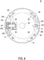
- FIG. 3 is a schematic perspective view illustrating a passive compliance mechanism according to a second embodiment of the present invention.
- FIG. 4 is a schematic top view illustrating the passive compliance mechanism of FIG. 3 .
- the passive compliance mechanism 20 is applied to a service robot, a collaborative robot, an industrial robot or any other appropriate robot.
- the passive compliance mechanism 20 is installed in a joint of an arm or a leg of the robot.
- the passive compliance mechanism 20 comprises a fixing member 21, a base 22, a first stiffness adjustment assembly 23 and a stiffness switching module 24.
- the fixing member 21 is assembled with the joint of the robot.
- the base 22 is installed on the fixing member 21 through a bearing (not shown).
- the base 22 is made of a flexible (or elastic) material.
- the base 22 is subjected to an elastic deformation according to the magnitude of the stiffness of the base 22. Consequently, the base 22 is moved relative to the fixing member 21. Under this circumstance, the base 22 provides the compliant function.
- the base 22 comprises a first notch 224, a second notch 221 and an elastic slice 222.
- the second notch 221 is a fan-shaped notch.
- the second notch 221 is concavely formed in the direction from an outer periphery of the base 22 to the center of the base 22.
- the elastic slice 222 is assembled with the base 22 and disposed within the first notch 224.
- the elastic slice 222 is protruded externally from the base 22 in the direction toward the outer periphery of the fixing member 21.
- a first end of the elastic slice 222 is connected with the base 22.
- a second end of the elastic slice 222 is located near the outer periphery of the fixing member 21.
- the elastic slice 222 is assembled with the base 22.
- the elastic slice 222 is integrally formed with the base 22.
- the first notch 224 is divided into two receiving spaces through the elastic slice 222.
- the first notch 224 and the second notch 221 are located at two opposite sides of the base 22.
- the first stiffness adjustment assembly 23 is installed on the fixing member 21.
- the first stiffness adjustment assembly 23 comprises a first linear guide 231, a first sliding block 232 and two first stopping blocks 233.
- the first linear guide 231 is installed on the fixing member 21. Moreover, the first linear guide 231 is aligned with the elastic slice 222.
- the first sliding block 232 is movably installed on the first linear guide 231.
- the two first stopping blocks 233 are fixedly disposed on the first sliding block 232 and synchronously moved with the first sliding block 232. Moreover, the two first stopping blocks 233 are contacted with two opposite sides of the elastic slice 222. Consequently, the elastic slice 222 is clamped by the two first stopping blocks 233.
- the stiffness of the base 22 is adjustable according to the position of the elastic slice 222 clamped by the two first stopping blocks 233. Moreover, the distance between the first end of the elastic slice 222 and the clamped position of the elastic slice 222 is an available length of the elastic slice 222.
- the magnitude of the stiffness of the base 22 is influenced by the available length of the elastic slice 222. That is, if the clamped position of the elastic slice 222 is changed, the magnitude of the stiffness of the base 22 is changed. In case that the clamped position of the elastic slice 222 is closer to the second end of the elastic slice 222, the stiffness of the base 22 is lower.
- the stiffness of the base 22 is higher.
- the two first stopping blocks 233 are moved to the first end of the elastic slice 222, the two first stopping blocks 233 are accommodated within the receiving spaces of the first notch 224, respectively.
- the first notch 224, the elastic slice 222 and the first stiffness adjustment assembly 23 are collaboratively defined as a first stiffness adjustment module.
- the first stiffness adjustment module can be used to adjust the magnitude of the stiffness of the base 22.
- the stiffness switching module 24 is installed on the fixing member 21 and aligned with the second notch 221.
- the stiffness switching module 24 comprises a second linear guide 241, a second sliding block 242 and a second stopping block 243.
- the second linear guide 241 is installed on the fixing member 21 and aligned with the second notch 221.
- the second sliding block 242 is movably installed on the second linear guide 241. Moreover, the second sliding block 242 can be moved to a first position or a second position.
- the second stopping block 243 is fixedly disposed on the second sliding block 242 and synchronously moved with the second sliding block 242.
- the second stopping block 243 is moved to the second notch 221 and engaged with the second notch 221, and thus the base 22 has the maximum stiffness. Meanwhile, even if an external force is applied to the base 22, the base 22 is not subjected to the elastic deformation because the second stopping block 243 is engaged with the second notch 221. Consequently, the base 22 is indirectly fixed on the fixing member 21. Since the base 22 is not subjected to the elastic deformation relative to the fixing member 21, the stiffness of the base 22 is similar to the stiffness of the fixing member 21. When the second sliding block 242 is moved to the second position, the second stopping block 243 is completely disengaged from the second notch 221.
- the second sliding block 242 For acquiring the maximum stiffness of the base 22, the second sliding block 242 is moved to the first position. Consequently, the second stopping block 243 is moved to the second notch 221 and engaged with the second notch 221. For dynamically adjusting stiffness of the base 22, the second sliding block 242 is moved to the second position. When the clamped position of the elastic slice 222 by the first stopping blocks 233 is changed, the magnitude of the stiffness of the base 22 is adjusted.
- the passive compliance mechanism 20 further comprises a magnetic driving module 17.
- the magnetic driving module 17 is installed on the fixing member 21 and located near the first sliding block 232.
- the magnetic driving module 17 drives the movement of the first sliding block 232 along the first linear guide 231 according to electromagnetic induction. It is noted that the way of driving the movement of the first sliding block 232 along the first linear guide 231 is not restricted.
- the use of the motor to drive to the cable rope to tow the sliding block along the linear guide is also feasible.
- the above driving method can be used to drive the stiffness switching module 24 in order to drive movement of the second sliding block 242 along the second linear guide 241.
- the passive compliance mechanism 20 further comprises a hollow pipe 29.
- the hollow pipe 29 runs the fixing member 21 and the base 22. A portion of the cable rope or any other wire of the passive compliance mechanism 20 can be wired through the hollow pipe 29. Consequently, the operation of the passive compliance mechanism 20 is not adversely affected by the cable rope or the wire.
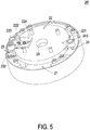
- FIG. 5 is a schematic perspective view illustrating a variant example of the passive compliance mechanism of FIG. 3 .
- the altitude of the elastic slice 222' is gradually decreased from the first end to the second end of the elastic slice 222'. Consequently, the efficacy of adjusting the stiffness by the passive compliance mechanism 20' is enhanced.
- FIG. 6 is a schematic top view illustrating another variant example of the passive compliance mechanism of FIG. 3 .
- the passive compliance mechanism 20' further comprises a second stiffness adjustment module.
- the second stiffness adjustment module comprises a first notch 224, an elastic slice 222 and a first stiffness adjustment assembly 23.
- the components, relationships and functions of the second stiffness adjustment module are similar to those of the first stiffness adjustment module, and are not redundantly described herein.
- the first stiffness adjustment module and the second stiffness adjustment module are located at two opposite sides of the fixing member 21.
- the first stiffness adjustment module and the second stiffness adjustment module are arranged near each other. The first stiffness adjustment module and the second stiffness adjustment module cooperate with each other to adjust the stiffness of the base.
- the passive compliance mechanism comprises at least three stiffness adjustment modules according to the practical requirements.
- the present invention provides the passive compliance mechanism.
- the stiffness adjustment assembly is used to adjust the stiffness of the base.
- the passive compliance mechanism can be applied to many kinds of the robots without the need of replacing any component or changing the design. For example, if the stiffness of the base is adjusted to the maximum value, the passive compliance mechanism is suitably applied to the industrial robot that requires high stiffness. If the stiffness of the base is adjusted to the lower value, the passive compliance mechanism is suitably applied to the service robot that requires high compliance. Alternatively, the passive compliance mechanism is suitably applied to the collaboratively robot that cooperates with the user. In other words, the passive compliance mechanism of the present invention is user-friendly and cost-effective.
- the passive compliance mechanism comprises plural stiffness adjustment modules.
- the sensor is used for measuring the displacement or the distortion angle of the base relative to the fixing member in response to the elastic deformation. According to the stiffness of the base and the displacement or the distortion angle of the base, the torque of the passive compliance mechanism is calculated.
Landscapes
- Engineering & Computer Science (AREA)
- Robotics (AREA)
- Mechanical Engineering (AREA)
- Manipulator (AREA)
- General Engineering & Computer Science (AREA)
- Manufacturing & Machinery (AREA)
- Quality & Reliability (AREA)
- Physics & Mathematics (AREA)
- General Physics & Mathematics (AREA)
- Automation & Control Theory (AREA)
Description
- The present invention relates to a passive compliance mechanism, and more particularly to a passive compliance mechanism capable of adjusting the magnitude of the stiffness.
- With increasing development of science and technology, robots have been widely used in various fields in order to enhance the production speed and reduce the labor cost. In some situations, the robot is equipped with a compliance mechanism, for example like in document
CN 105 599 004 . The use of the compliance mechanism can comply with the flexible operation for the assembly process and enhance the safety of the robot that is in direct contact with the user (e.g., the service robot). Due to the compliance mechanism, the robot has the compliant property. Generally, the compliance mechanisms are divided into two types, i.e., an active compliance mechanism and a passive compliance mechanism. By absorbing energy or generating a compliant action, the passive compliance mechanism achieves the compliance. Since the response rate is very fast, the passive compliance mechanism is widely applied to various kinds of robots. - Conventionally, the passive compliance mechanism uses the elastic force of a spring to achieve the compliance efficacy. Since the elasticity coefficient of the spring used in the conventional passive compliance mechanism is fixed, the stiffness of the conventional passive compliance mechanism is fixed and unable to be adjusted. If the conventional passive compliance mechanism is applied to a different working environment or a different robot, it is necessary to adjust the stiffness. In accordance with the conventional approach of adjusting the stiffness, the spring is replaced with a new one or the design of the passive compliance mechanism is changed. In other words, the applications of the conventional passive compliance mechanism are insufficient and the fabricating cost is high.
- Therefore, there is a need of providing an improved passive compliance mechanism in order to overcome the above drawbacks.
- An object of the present invention provides a passive compliance mechanism capable of adjusting the magnitude of the stiffness in order to overcome the drawbacks of the conventional technologies.
- In accordance with an aspect of the present invention, there is provided a passive compliance mechanism. The passive compliance mechanism includes a fixing member, a base and a stiffness adjustment assembly. The base is installed on the fixing member, and includes two notches and an elastic slice. The two notches are arranged side by side. The elastic slice is arranged between the two notches and protruded externally from the base in a direction toward an outer periphery of the fixing member. A first end of the elastic slice is connected with the base. A second end of the elastic slice is located near the outer periphery of the fixing member. The stiffness adjustment assembly is installed on the fixing member, and includes a linear guide, a sliding block and two stopping blocks. The linear guide is installed on the fixing member and aligned with the elastic slice. The sliding block is movably installed on the linear guide. The two stopping blocks are fixedly disposed on the sliding block and synchronously moved with the sliding block. The two stopping blocks are contacted with two opposite sides of the elastic slice to clamp the elastic slice. A stiffness of the base is adjustable according to a clamped position of the elastic slice.
- In accordance with another aspect of the present invention, there is provided a passive compliance mechanism. The passive compliance mechanism includes a fixing member, a base, a first stiffness adjustment assembly and a second stiffness adjustment assembly. The base is installed on the fixing member, and includes a first notch, a second notch and an elastic slice. The elastic slice is installed on the base, accommodated within the first notch, and protruded externally from the base in a direction toward an outer periphery of the fixing member. A first end of the elastic slice is connected with the base. A second end of the elastic slice is located near the outer periphery of the fixing member. The first stiffness adjustment assembly is installed on the fixing member, and includes a first linear guide, a first sliding block and two first stopping blocks. The first linear guide is installed on the fixing member and aligned with the elastic slice. The first sliding block is movably installed on the first linear guide. The two first stopping blocks are fixedly disposed on the first sliding block and synchronously moved with the first sliding block. The two first stopping blocks are contacted with two opposite sides of the elastic slice to clamp the elastic slice. A stiffness of the base is adjustable according to a clamped position of the elastic slice. The stiffness switching module is installed on the fixing member, and includes a second linear guide, a second sliding block and a second stopping block. The second linear guide is installed on the fixing member. The second sliding block is movably installed on the first linear guide and selectively moved to a first position or a second position. The second stopping block is fixedly disposed on the second sliding block and synchronously moved with the second sliding block. When the second sliding block is moved to the first position, the second stopping block is moved to the second notch and engaged with the second notch, so that the base has the maximum stiffness. When the second sliding block is moved to the second position, the second stopping block is disengaged from the second notch.
- The above contents of the present invention will become more readily apparent to those ordinarily skilled in the art after reviewing the following detailed description and accompanying drawings, in which:
-
-
FIG. 1 is a schematic perspective view illustrating a passive compliance mechanism according to a first embodiment of the present invention; -
FIG. 2 is a schematic perspective view illustrating a variant example of the passive compliance mechanism ofFIG. 1 ; -
FIG. 3 is a schematic perspective view illustrating a passive compliance mechanism according to a second embodiment of the present invention; -
FIG. 4 is a schematic top view illustrating the passive compliance mechanism ofFIG. 3 ; -
FIG. 5 is a schematic perspective view illustrating a variant example of the passive compliance mechanism ofFIG. 3 ; and -
FIG. 6 is a schematic top view illustrating another variant example of the passive compliance mechanism ofFIG. 3 . - The present invention will now be described more specifically with reference to the following embodiments. It is to be noted that the following descriptions of preferred embodiments of this invention are presented herein for purpose of illustration and description only. It is not intended to be exhaustive or to be limited to the precise form disclosed.
-
FIG. 1 is a schematic perspective view illustrating a passive compliance mechanism according to a first embodiment of the present invention. As shown inFIG. 1 , thepassive compliance mechanism 10 is applied to a service robot, a collaborative robot, an industrial robot or any other appropriate robot. Thepassive compliance mechanism 10 is installed in a joint of an arm or a leg of the robot. In an embodiment, thepassive compliance mechanism 10 comprises afixing member 11, abase 12 and astiffness adjustment assembly 13. - The fixing
member 11 is assembled with the joint of the robot. Thebase 12 is installed on the fixingmember 11 through a bearing (not shown). Thebase 12 is made of a flexible (or elastic) material. When an external force is applied to thebase 12, thebase 12 is subjected to an elastic deformation according to the magnitude of the stiffness of thebase 12. Consequently, thebase 12 is moved relative to the fixingmember 11. Under this circumstance, thebase 12 provides the compliant function. In this embodiment, thebase 12 comprises twonotches 121 and anelastic slice 122. The twonotches 121 are arranged side by side. Moreover, the twonotches 121 are concavely formed in the direction from an outer periphery of the base 12 to the center of thebase 12. Theelastic slice 122 is arranged between the twonotches 121. Moreover, theelastic slice 122 is protruded externally from the base 12 in the direction toward the outer periphery of the fixingmember 11. A first end of theelastic slice 122 is connected with thebase 12. A second end of theelastic slice 122 is located near the outer periphery of the fixingmember 11. Preferably, theelastic slice 122 is integrally formed with thebase 12. - The
stiffness adjustment assembly 13 is installed on the fixingmember 11. In an embodiment, thestiffness adjustment assembly 13 comprises alinear guide 131, a slidingblock 132 and two stoppingblocks 133. Thelinear guide 131 is installed on the fixingmember 11. Moreover, thelinear guide 131 is aligned with theelastic slice 122. The slidingblock 132 is movably installed on thelinear guide 131. The two stoppingblocks 133 are fixedly disposed on the slidingblock 132 and synchronously moved with the slidingblock 132. Moreover, the two stoppingblocks 133 are contacted with two opposite sides of theelastic slice 122. Consequently, theelastic slice 122 is clamped by the two stoppingblocks 133. The stiffness of thebase 12 is adjustable according to the position of theelastic slice 122 clamped by the two stoppingblocks 133. The twonotches 121, theelastic slice 122 and thestiffness adjustment assembly 13 are collaboratively defined as a first stiffness adjustment module. The first stiffness adjustment module can be used to adjust the magnitude of the stiffness of thebase 12. - Preferably but not exclusively, the sizes and shapes of the two
notches 121 match the sizes and shapes of the two stoppingblocks 133. The twonotches 121 are concavely formed in the direction from the outer periphery of the base 12 to the center of thebase 12. Consequently, the two stoppingblocks 133 can be engaged with the twonotches 121. As mentioned above, the two stoppingblocks 133 are moved with the slidingblock 132. When the two stoppingblocks 133 are moved to the twonotches 121 and engaged with the twonotches 121, thebase 12 has the maximum stiffness. Meanwhile, even if an external force is applied to thebase 12, thebase 12 is not subjected to the elastic deformation because the two stoppingblocks 133 are engaged with the twonotches 121. Consequently, thebase 12 is indirectly fixed on the fixingmember 11. Since thebase 12 is not subjected to the elastic deformation relative to the fixingmember 11, the stiffness of thebase 12 is similar to the stiffness of the fixingmember 11. When the two stoppingblocks 133 are detached from the twonotches 121 and disengaged from the twonotches 121, the two stoppingblocks 133 are moved between the first end and the second end of theelastic slice 122. Consequently, the position of theelastic slice 122 clamped by the two stoppingblocks 133 is adjustable. Moreover, the distance between the first end of theelastic slice 122 and the clamped position of theelastic slice 122 is an available length of theelastic slice 122. The magnitude of the stiffness of thebase 12 is influenced by the available length of theelastic slice 122. That is, if the clamped position of theelastic slice 122 is changed, the magnitude of the stiffness of thebase 12 is changed. In case that the clamped position of theelastic slice 122 is closer to the second end of theelastic slice 122, the stiffness of thebase 12 is lower. Whereas, in case that the clamped position of theelastic slice 122 is closer to the first end of theelastic slice 122, the stiffness of thebase 12 is higher. - From the above descriptions, the flexible (or elastic)
base 12 of thepassive compliance mechanism 10 is capable of absorbing the impact. Consequently, thepassive compliance mechanism 10 and the robot with thepassive compliance mechanism 10 achieve the compliance. Moreover, the stiffness of the base 12 can be adjusted through thestiffness adjustment assembly 13. Consequently, the compliance of thepassive compliance mechanism 10 is correspondingly adjusted. Thepassive compliance mechanism 10 can be applied to many kinds of the robots without the need of replacing any component or changing the design. For example, if the stiffness of thebase 12 is adjusted to the maximum value, thepassive compliance mechanism 10 is suitably applied to the industrial robot that requires high stiffness. If the stiffness of thebase 12 is adjusted to the lower value, thepassive compliance mechanism 10 is suitably applied to the service robot that requires high compliance. Alternatively, thepassive compliance mechanism 10 is suitably applied to the collaboratively robot that cooperates with the user. In other words, thepassive compliance mechanism 10 of the present invention is user-friendly and cost-effective. - In some embodiments, the altitude of the first end of the
elastic slice 122 is equal to the altitude of the second end of theelastic slice 122. For increasing the adjustable stiffness range of the base 12 according to the clamped position of theelastic slice 122, the altitude of theelastic slice 122 is gradually decreased from the first end to the second end of theelastic slice 122. - Please refer to
FIG. 1 again. Thepassive compliance mechanism 10 further comprises acable rope 16 and amotor 15. Thecable rope 16 is connected between themotor 15 and the slidingblock 132. When thecable rope 16 is driven by themotor 15, the slidingblock 132 is towed by thecable rope 16. Consequently, the slidingblock 132 is moved along thelinear guide 131. It is noted that the way of driving the movement of the slidingblock 132 along thelinear guide 131 is not restricted. For example, in another embodiment, the movement of the slidingblock 132 is driven according to electromagnetic induction. - The fixing
member 11 further comprises a raisedblock 111. The base 12 further comprises anopening 123 corresponding to the raisedblock 111. After the raisedblock 111 is penetrated through theopening 123, thebase 12 is sheathed around the raisedblock 111. Consequently, thebase 12 is installed on the fixingmember 11. Thepassive compliance mechanism 10 further comprises ahollow pipe 19. Thehollow pipe 19 runs through the center of the fixingmember 11 and the center of the raisedblock 111. A portion of thecable rope 16 or any other wire of thepassive compliance mechanism 10 can be wired through thehollow pipe 19. Consequently, the operation of thepassive compliance mechanism 10 is not adversely affected by thecable rope 16 or the wire. - Moreover, the
stiffness adjustment assembly 13 further comprises two position-limitingstructures 134. The two position-limitingstructures 134 are separately disposed on the fixingmember 11. One of the two position-limitingstructures 134 is located near the center of the fixingmember 11. The other of the two position-limitingstructures 134 is located near the outer periphery of the fixingmember 11. The range between the two position-limitingstructures 134 is substantially a movable range of the slidingblock 132. The length of the movable range is slightly larger than or equal to the displacement of the two stoppingblocks 133 from the twonotches 121 to the second end of theelastic slice 122. The slidingblock 132 further comprises aprotrusion structure 135. Theprotrusion structure 135 is protruded from a lateral surface of the slidingblock 132. Moreover, theprotrusion structure 135 is arranged between the two position-limitingstructures 134. While the slidingblock 132 is moved along thelinear guide 131, the movable range of the protrusion structure 135 (or the sliding block 132) is limited by the two position-limitingstructures 134. That is, when the two stoppingblocks 133 are moved to the twonotches 121 and engaged with the twonotches 121, the slidingblock 132 cannot be continuously moved toward the center of the fixingmember 11. Similarly, when the two stoppingblocks 133 are moved to the position corresponding to the second end of theelastic slice 122, the slidingblock 132 cannot be continuously moved toward the outer periphery of the fixingmember 11. - In an embodiment, the
passive compliance mechanism 10 further comprises asensor 14. Thesensor 14 is aligned with thebase 12 and installed on the fixingmember 11. Thesensor 14 is used for measuring the displacement of the base 12 relative to the fixingmember 11 in response to the elastic deformation. After the magnitude of the stiffness of thebase 12 is obtained and the displacement of thebase 12 is measured by thesensor 14, the torque of thepassive compliance mechanism 10 is calculated. Consequently, thepassive compliance mechanism 10 is capable of sensing the torque. In another embodiment, thesensor 14 is used for measuring the torque angle of thepassive compliance mechanism 10. - For increasing the precision of adjusting the stiffness, the passive compliance mechanism is modified.
FIG. 2 is a schematic perspective view illustrating a variant example of the passive compliance mechanism ofFIG. 1 . In this embodiment, the passive compliance mechanism 10' further comprises a second stiffness adjustment module. The second stiffness adjustment module comprises twonotches 121, anelastic slice 122 and astiffness adjustment assembly 13. The components, relationships and functions of the second stiffness adjustment module are similar to those of the first stiffness adjustment module, and are not redundantly described herein. In an embodiment, the first stiffness adjustment module and the second stiffness adjustment module are located at two opposite sides of the fixingmember 11. In another embodiment, the first stiffness adjustment module and the second stiffness adjustment module are arranged near each other. The first stiffness adjustment module and the second stiffness adjustment module cooperate with each other to adjust the stiffness of the base. In some other embodiments, the passive compliance mechanism comprises at least three stiffness adjustment modules according to the practical requirements. -
FIG. 3 is a schematic perspective view illustrating a passive compliance mechanism according to a second embodiment of the present invention.FIG. 4 is a schematic top view illustrating the passive compliance mechanism ofFIG. 3 . Thepassive compliance mechanism 20 is applied to a service robot, a collaborative robot, an industrial robot or any other appropriate robot. Thepassive compliance mechanism 20 is installed in a joint of an arm or a leg of the robot. In an embodiment, thepassive compliance mechanism 20 comprises a fixingmember 21, abase 22, a firststiffness adjustment assembly 23 and astiffness switching module 24. - The fixing
member 21 is assembled with the joint of the robot. Thebase 22 is installed on the fixingmember 21 through a bearing (not shown). Thebase 22 is made of a flexible (or elastic) material. When an external force is applied to thebase 22, thebase 22 is subjected to an elastic deformation according to the magnitude of the stiffness of thebase 22. Consequently, thebase 22 is moved relative to the fixingmember 21. Under this circumstance, thebase 22 provides the compliant function. In this embodiment, thebase 22 comprises afirst notch 224, asecond notch 221 and anelastic slice 222. Preferably but not exclusively, thesecond notch 221 is a fan-shaped notch. Moreover, thesecond notch 221 is concavely formed in the direction from an outer periphery of the base 22 to the center of thebase 22. Theelastic slice 222 is assembled with thebase 22 and disposed within thefirst notch 224. Moreover, theelastic slice 222 is protruded externally from the base 22 in the direction toward the outer periphery of the fixingmember 21. A first end of theelastic slice 222 is connected with thebase 22. A second end of theelastic slice 222 is located near the outer periphery of the fixingmember 21. In an embodiment, theelastic slice 222 is assembled with thebase 22. Alternatively, theelastic slice 222 is integrally formed with thebase 22. Moreover, thefirst notch 224 is divided into two receiving spaces through theelastic slice 222. Moreover, thefirst notch 224 and thesecond notch 221 are located at two opposite sides of thebase 22. - The first
stiffness adjustment assembly 23 is installed on the fixingmember 21. In an embodiment, the firststiffness adjustment assembly 23 comprises a firstlinear guide 231, a first slidingblock 232 and two first stopping blocks 233. The firstlinear guide 231 is installed on the fixingmember 21. Moreover, the firstlinear guide 231 is aligned with theelastic slice 222. The first slidingblock 232 is movably installed on the firstlinear guide 231. The two first stoppingblocks 233 are fixedly disposed on the first slidingblock 232 and synchronously moved with the first slidingblock 232. Moreover, the two first stoppingblocks 233 are contacted with two opposite sides of theelastic slice 222. Consequently, theelastic slice 222 is clamped by the two first stopping blocks 233. The stiffness of thebase 22 is adjustable according to the position of theelastic slice 222 clamped by the two first stopping blocks 233. Moreover, the distance between the first end of theelastic slice 222 and the clamped position of theelastic slice 222 is an available length of theelastic slice 222. The magnitude of the stiffness of thebase 22 is influenced by the available length of theelastic slice 222. That is, if the clamped position of theelastic slice 222 is changed, the magnitude of the stiffness of thebase 22 is changed. In case that the clamped position of theelastic slice 222 is closer to the second end of theelastic slice 222, the stiffness of thebase 22 is lower. Whereas, in case that the clamped position of theelastic slice 222 is closer to the first end of theelastic slice 222, the stiffness of thebase 22 is higher. When the two first stoppingblocks 233 are moved to the first end of theelastic slice 222, the two first stoppingblocks 233 are accommodated within the receiving spaces of thefirst notch 224, respectively. Moreover, thefirst notch 224, theelastic slice 222 and the firststiffness adjustment assembly 23 are collaboratively defined as a first stiffness adjustment module. The first stiffness adjustment module can be used to adjust the magnitude of the stiffness of thebase 22. - The
stiffness switching module 24 is installed on the fixingmember 21 and aligned with thesecond notch 221. In an embodiment, thestiffness switching module 24 comprises a secondlinear guide 241, a second slidingblock 242 and a second stoppingblock 243. The secondlinear guide 241 is installed on the fixingmember 21 and aligned with thesecond notch 221. The second slidingblock 242 is movably installed on the secondlinear guide 241. Moreover, the second slidingblock 242 can be moved to a first position or a second position. The second stoppingblock 243 is fixedly disposed on the second slidingblock 242 and synchronously moved with the second slidingblock 242. - When the second sliding
block 242 is moved to the first position, the second stoppingblock 243 is moved to thesecond notch 221 and engaged with thesecond notch 221, and thus thebase 22 has the maximum stiffness. Meanwhile, even if an external force is applied to thebase 22, thebase 22 is not subjected to the elastic deformation because the second stoppingblock 243 is engaged with thesecond notch 221. Consequently, thebase 22 is indirectly fixed on the fixingmember 21. Since thebase 22 is not subjected to the elastic deformation relative to the fixingmember 21, the stiffness of thebase 22 is similar to the stiffness of the fixingmember 21. When the second slidingblock 242 is moved to the second position, the second stoppingblock 243 is completely disengaged from thesecond notch 221. - For acquiring the maximum stiffness of the
base 22, the second slidingblock 242 is moved to the first position. Consequently, the second stoppingblock 243 is moved to thesecond notch 221 and engaged with thesecond notch 221. For dynamically adjusting stiffness of thebase 22, the second slidingblock 242 is moved to the second position. When the clamped position of theelastic slice 222 by the first stoppingblocks 233 is changed, the magnitude of the stiffness of thebase 22 is adjusted. - In an embodiment, the
passive compliance mechanism 20 further comprises amagnetic driving module 17. Themagnetic driving module 17 is installed on the fixingmember 21 and located near the first slidingblock 232. Themagnetic driving module 17 drives the movement of the first slidingblock 232 along the firstlinear guide 231 according to electromagnetic induction. It is noted that the way of driving the movement of the first slidingblock 232 along the firstlinear guide 231 is not restricted. For example, as described in the first embodiment, the use of the motor to drive to the cable rope to tow the sliding block along the linear guide is also feasible. The above driving method can be used to drive thestiffness switching module 24 in order to drive movement of the second slidingblock 242 along the secondlinear guide 241. Thepassive compliance mechanism 20 further comprises ahollow pipe 29. Thehollow pipe 29 runs the fixingmember 21 and thebase 22. A portion of the cable rope or any other wire of thepassive compliance mechanism 20 can be wired through thehollow pipe 29. Consequently, the operation of thepassive compliance mechanism 20 is not adversely affected by the cable rope or the wire. - In the embodiment of
FIG. 4 , the altitude of the first end of theelastic slice 222 is equal to the altitude of the second end of theelastic slice 222.FIG. 5 is a schematic perspective view illustrating a variant example of the passive compliance mechanism ofFIG. 3 . For increasing the adjustable stiffness range of the base 22 according to the clamped position of the elastic slice 222', the altitude of the elastic slice 222' is gradually decreased from the first end to the second end of the elastic slice 222'. Consequently, the efficacy of adjusting the stiffness by the passive compliance mechanism 20' is enhanced. - For increasing the precision of adjusting the stiffness, the passive compliance mechanism is modified.
FIG. 6 is a schematic top view illustrating another variant example of the passive compliance mechanism ofFIG. 3 . In this embodiment, the passive compliance mechanism 20' further comprises a second stiffness adjustment module. The second stiffness adjustment module comprises afirst notch 224, anelastic slice 222 and a firststiffness adjustment assembly 23. The components, relationships and functions of the second stiffness adjustment module are similar to those of the first stiffness adjustment module, and are not redundantly described herein. In an embodiment, the first stiffness adjustment module and the second stiffness adjustment module are located at two opposite sides of the fixingmember 21. In another embodiment, the first stiffness adjustment module and the second stiffness adjustment module are arranged near each other. The first stiffness adjustment module and the second stiffness adjustment module cooperate with each other to adjust the stiffness of the base. In some other embodiments, the passive compliance mechanism comprises at least three stiffness adjustment modules according to the practical requirements. - From the above descriptions, the present invention provides the passive compliance mechanism. The stiffness adjustment assembly is used to adjust the stiffness of the base. The passive compliance mechanism can be applied to many kinds of the robots without the need of replacing any component or changing the design. For example, if the stiffness of the base is adjusted to the maximum value, the passive compliance mechanism is suitably applied to the industrial robot that requires high stiffness. If the stiffness of the base is adjusted to the lower value, the passive compliance mechanism is suitably applied to the service robot that requires high compliance. Alternatively, the passive compliance mechanism is suitably applied to the collaboratively robot that cooperates with the user. In other words, the passive compliance mechanism of the present invention is user-friendly and cost-effective. For increasing the precision of adjusting the stiffness, the passive compliance mechanism comprises plural stiffness adjustment modules. A portion of the cable rope or any other wire of the passive compliance mechanism can be wired through the hollow pipe. Consequently, the operation of the passive compliance mechanism is not adversely affected by the cable rope or the wire. Moreover, the sensor is used for measuring the displacement or the distortion angle of the base relative to the fixing member in response to the elastic deformation. According to the stiffness of the base and the displacement or the distortion angle of the base, the torque of the passive compliance mechanism is calculated.
Claims (15)
- A passive compliance mechanism (10, 10'), comprising:a fixing member (11);a base (12) installed on the fixing member (11), and comprising two notches (121) and an elastic slice (122), wherein the two notches (121) are arranged side by side, the elastic slice (122) is arranged between the two notches (121) and protruded externally from the base (12) in a direction toward an outer periphery of the fixing member (11), a first end of the elastic slice (122) is connected with the base (12), and a second end of the elastic slice (122) is located near the outer periphery of the fixing member (11); anda stiffness adjustment assembly (13) installed on the fixing member (11), and comprising:a linear guide (131) installed on the fixing member (11) and aligned with the elastic slice (122);a sliding block (132) movably installed on the linear guide (131); andtwo stopping blocks (133) fixedly disposed on the sliding block (132) and synchronously moved with the sliding block (132), wherein the two stopping blocks (133) are contacted with two opposite sides of the elastic slice (122) to clamp the elastic slice (122), and a stiffness of the base (12) is adjustable according to a clamped position of the elastic slice (122).
- The passive compliance mechanism (10, 10') according to claim 1, wherein when the clamped position of the elastic slice (122) clamped by the two stopping blocks (133) is closer to the first end of the elastic slice (122), the stiffness of the base (12) is higher, wherein when the clamped position of the elastic slice (122) clamped by the two stopping blocks (133) is closer to the second end of the elastic slice (122), the stiffness of the base (12) is lower, wherein when the two stopping blocks (133) are moved by the sliding block (132) to the two notches (121) and engaged with the two notches (121), the stiffness of the base (12) has the maximum value.
- The passive compliance mechanism (10, 10') according to claim 1 or 2, wherein the elastic slice (122) is integrally formed with the base (12), wherein an altitude of the elastic slice (122) is gradually decreased from the first end to the second end of the elastic slice (122).
- The passive compliance mechanism (10, 10') according to one of the preceding claims, wherein the passive compliance mechanism (10, 10') further comprises a cable rope (16), and the cable rope (16) is connected between a motor (15) and the sliding block (132), wherein when the cable rope (16) is driven by the motor (15), the sliding block (132) is towed by the cable rope (16), so that the sliding block (132) is moved along the linear guide (131).
- The passive compliance mechanism (10, 10') according to one of the preceding claims, wherein the fixing member (11) further comprises a raised block (111), and the base (12) further comprises an opening (123), wherein the raised block (111) is penetrated through the opening (123), so that the base (12) is installed on the fixing member (11), wherein the passive compliance mechanism (10, 10') further comprises a hollow pipe (19), the hollow pipe (19) runs through a center of the fixing member (11) and a center of the raised block (111).
- The passive compliance mechanism (10, 10') according to one of the preceding claims, further comprising a sensor (14) corresponding to the base (12), wherein the sensor (14) is installed on the fixing member (11) to measure a displacement or a distortion angle of the base (12) relative to the fixing member (11) in response to an elastic deformation of the base (12).
- The passive compliance mechanism (10, 10') according to one of the preceding claims, wherein the two notches (121), the elastic slice (122) and the stiffness adjustment assembly (13) are collaboratively defined as a first stiffness adjustment module, and the passive compliance mechanism (10, 10') further comprises a second stiffness adjustment module with the same structure as the first stiffness adjustment module, wherein the first stiffness adjustment module and the second stiffness adjustment module are located at two opposite sides of the fixing member (11), and the first stiffness adjustment module and the second stiffness adjustment module cooperate with each other to adjust the stiffness of the base (12).
- The passive compliance mechanism (10, 10') according to one of the preceding claims, wherein the stiffness adjustment assembly (13) further comprises two position-limiting structures (134), and the two position-limiting structures (134) are separately disposed on the fixing member (11), wherein one of the two position-limiting structures (134) is located near a center of the fixing member (11), and the other of the two position-limiting structures (134) is located near the outer periphery of the fixing member (11), so that a movable range of the sliding block (132) is determined by the two position-limiting structures (134).
- The passive compliance mechanism (10, 10') according to claim 8, wherein the sliding block (132) further comprises a protrusion structure (135), and the protrusion structure (135) is protruded from a lateral surface of the sliding block (132) and arranged between the two position-limiting structures (134), wherein while the sliding block (132) is moved along the linear guide (131), the movable range of the sliding block (132) is limited by the two position-limiting structures (134) through the protrusion structure (135), wherein a length of the movable range is slightly larger than or equal to a displacement of the two stopping blocks (133) from the two notches (121) to the second end of the elastic slice (122).
- A passive compliance mechanism (20, 20', 20"), comprising:a fixing member (21);a base (22) installed on the fixing member (21), and comprising a first notch (224), a second notch (221) and an elastic slice (222), wherein the elastic slice (222) is installed on the base (22), accommodated within the first notch (224), and protruded externally from the base (22) in a direction toward an outer periphery of the fixing member (21), a first end of the elastic slice (222) is connected with the base (22), and a second end of the elastic slice (222) is located near the outer periphery of the fixing member (21);a first stiffness adjustment assembly (23) installed on the fixing member (21), and comprising:a first linear guide (231) installed on the fixing member (21) and aligned with the elastic slice (222);a first sliding block (232) movably installed on the first linear guide (231); andtwo first stopping blocks (233) fixedly disposed on the first sliding block (232) and synchronously moved with the first sliding block (232), wherein the two first stopping blocks (233) are contacted with two opposite sides of the elastic slice (222) to clamp the elastic slice (222), and a stiffness of the base (22) is adjustable according to a clamped position of the elastic slice (222); anda stiffness switching module (24) installed on the fixing member (21), and comprising:a second linear guide (241) installed on the fixing member (21);a second sliding block (242) movably installed on the first linear guide (241) and selectively moved to a first position or a second position; anda second stopping block (243) fixedly disposed on the second sliding block (242) and synchronously moved with the second sliding block (242), wherein when the second sliding block (242) is moved to the first position, the second stopping block (243) is moved to the second notch (221) and engaged with the second notch (221), so that the base (22) has the maximum stiffness, wherein when the second sliding block (242) is moved to the second position, the second stopping block (243) is disengaged from the second notch (221).
- The passive compliance mechanism (20, 20', 20") according to claim 10, wherein when the second sliding block (242) is moved to the second position and the clamped position of the elastic slice (222) clamped by the two first stopping blocks (233) is closer to the first end of the elastic slice (222), the stiffness of the base (22) is higher, wherein when the second sliding block (242) is moved to the second position and the clamped position of the elastic slice (222) clamped by the two first stopping blocks (233) is closer to the second end of the elastic slice (222), the stiffness of the base (22) is lower.
- The passive compliance mechanism (20, 20', 20") according to claim 10 or 11, wherein the elastic slice (222) is assembled with the base (22), wherein an altitude of the elastic slice (222') is gradually decreased from the first end to the second end of the elastic slice (222').
- The passive compliance mechanism (20, 20', 20") according to one of claims 10-12, further comprising a magnetic driving module (17), wherein the magnetic driving module (17) is installed on the fixing member (21) and located near the first sliding block (232), and the magnetic driving module (17) drives a movement of the first sliding block (232) along the first linear guide (231) according to electromagnetic induction.
- The passive compliance mechanism (20, 20', 20") according to one of claims 10-13, further comprising a hollow pipe (29), wherein the hollow pipe (29) runs through the fixing member (21) and the base (22).
- The passive compliance mechanism (20, 20', 20") according to one of claims 10-14, wherein the first notch (224), the elastic slice (222) and the first stiffness adjustment assembly (23) are collaboratively defined as a first stiffness adjustment module, and the passive compliance mechanism (20, 20', 20") further comprises a second stiffness adjustment module with the same structure as the first stiffness adjustment module, wherein the first stiffness adjustment module and the second stiffness adjustment module are arranged near each other or located at two opposite sides of the fixing member (21), and the first stiffness adjustment module and the second stiffness adjustment module cooperate with each other to adjust the stiffness of the base (22).
Priority Applications (1)
| Application Number | Priority Date | Filing Date | Title |
|---|---|---|---|
| PL17192816T PL3378609T3 (en) | 2017-03-23 | 2017-09-25 | Passive compliance mechanism |
Applications Claiming Priority (1)
| Application Number | Priority Date | Filing Date | Title |
|---|---|---|---|
| TW106109706A TWI593527B (en) | 2017-03-23 | 2017-03-23 | Passive compliant mechanism |
Publications (2)
| Publication Number | Publication Date |
|---|---|
| EP3378609A1 EP3378609A1 (en) | 2018-09-26 |
| EP3378609B1 true EP3378609B1 (en) | 2019-07-24 |
Family
ID=59968997
Family Applications (1)
| Application Number | Title | Priority Date | Filing Date |
|---|---|---|---|
| EP17192816.1A Active EP3378609B1 (en) | 2017-03-23 | 2017-09-25 | Passive compliance mechanism |
Country Status (7)
| Country | Link |
|---|---|
| US (1) | US20180275640A1 (en) |
| EP (1) | EP3378609B1 (en) |
| JP (1) | JP6571147B2 (en) |
| ES (1) | ES2748125T3 (en) |
| HU (1) | HUE044566T2 (en) |
| PL (1) | PL3378609T3 (en) |
| TW (1) | TWI593527B (en) |
Families Citing this family (7)
| Publication number | Priority date | Publication date | Assignee | Title |
|---|---|---|---|---|
| US11931888B2 (en) * | 2019-01-10 | 2024-03-19 | Ati Industrial Automation, Inc. | Robotic tool having selectable compliance modes |
| CN109732641B (en) * | 2019-01-28 | 2021-09-07 | 西安交通大学 | Two-state variable-rigidity compliant joint and operation method |
| CN109807938B (en) * | 2019-03-26 | 2020-12-29 | 清华大学 | Non-guide rail type variable stiffness driver |
| CN113146674B (en) * | 2020-01-22 | 2022-12-13 | 杭州新剑机器人技术股份有限公司 | Large flexible serial elastic unit and robot comprising same |
| CN111805145B (en) * | 2020-07-20 | 2022-05-10 | 湖南天一智能科技有限公司 | Clamp system control method and clamp system |
| CN112025735A (en) * | 2020-09-10 | 2020-12-04 | 河南工业职业技术学院 | Passive compliant robot polishing device based on visual perception |
| CN113084861B (en) * | 2021-04-20 | 2022-07-05 | 沈阳理工大学 | Series reconfigurable variable-stiffness robot joint structure based on permanent magnet springs |
Family Cites Families (8)
| Publication number | Priority date | Publication date | Assignee | Title |
|---|---|---|---|---|
| KR100861953B1 (en) * | 2007-10-05 | 2008-10-09 | 삼성전자주식회사 | Compliant joint |
| KR101412130B1 (en) * | 2008-03-14 | 2014-06-27 | 삼성전자주식회사 | Compliant Joint |
| KR101195700B1 (en) * | 2010-04-05 | 2012-10-29 | 고려대학교 산학협력단 | Variable stiffness actuation unit |
| TW201242732A (en) * | 2011-04-19 | 2012-11-01 | Prec Machinery Res & Dev Ct | Compliance mechanism |
| CN103846930B (en) * | 2012-12-27 | 2015-11-25 | 中国科学院合肥物质科学研究院 | Be applied to the passive type compliance impedance mechanisms on service robot mechanical arm |
| JP6556697B2 (en) * | 2013-04-24 | 2019-08-07 | マーケット ユニバーシティー | Variable stiffness actuator with wide stiffness range |
| CN103600358A (en) * | 2013-11-29 | 2014-02-26 | 中国科学院合肥物质科学研究院 | Passive compliance impedance mechanism and mechanical arm |
| CN105599004B (en) * | 2016-03-23 | 2017-06-20 | 华南理工大学 | A kind of adjustable Robot elastic joint of rigidity |
-
2017
- 2017-03-23 TW TW106109706A patent/TWI593527B/en active
- 2017-09-05 US US15/695,301 patent/US20180275640A1/en not_active Abandoned
- 2017-09-25 ES ES17192816T patent/ES2748125T3/en active Active
- 2017-09-25 PL PL17192816T patent/PL3378609T3/en unknown
- 2017-09-25 EP EP17192816.1A patent/EP3378609B1/en active Active
- 2017-09-25 HU HUE17192816 patent/HUE044566T2/en unknown
- 2017-09-25 JP JP2017184016A patent/JP6571147B2/en active Active
Non-Patent Citations (1)
| Title |
|---|
| None * |
Also Published As
| Publication number | Publication date |
|---|---|
| TWI593527B (en) | 2017-08-01 |
| JP2018158434A (en) | 2018-10-11 |
| PL3378609T3 (en) | 2019-11-29 |
| EP3378609A1 (en) | 2018-09-26 |
| TW201834806A (en) | 2018-10-01 |
| JP6571147B2 (en) | 2019-09-04 |
| HUE044566T2 (en) | 2019-11-28 |
| US20180275640A1 (en) | 2018-09-27 |
| ES2748125T3 (en) | 2020-03-13 |
Similar Documents
| Publication | Publication Date | Title |
|---|---|---|
| EP3378609B1 (en) | Passive compliance mechanism | |
| KR101848115B1 (en) | Electric cylinder system | |
| US9095984B2 (en) | Force control robot | |
| US9397586B2 (en) | Ultrasonic wave motor and ultrasonic wave motor-equipped device | |
| CN108015561B (en) | Motion platform capable of enlarging single-drive rigid-flexible coupling working area | |
| CN108386447B (en) | Rigid-flexible coupling sliding block and motion platform | |
| US20140167341A1 (en) | Clamping device | |
| KR20130138817A (en) | Electric cylinder and electric cylinder system | |
| US11000958B2 (en) | Deflection element | |
| US7834517B2 (en) | Linear drive ultrasonic motor | |
| EP1821000A2 (en) | Friction drive unit | |
| KR100396021B1 (en) | Ultra-precision moving apparatus | |
| CN103192279B (en) | Two-dimension decoupling motion platform | |
| CN101871549A (en) | Three-degree-of-freedom precision-positioning workbench | |
| JPS63156684A (en) | Safety coupling for robot | |
| CN108621123B (en) | Passive compliance mechanism | |
| US20110291383A1 (en) | Position adjustable coupler and hitch equipped therewith | |
| CN109465651B (en) | Friction type rigidity switching device, rigid-flexible coupling motion platform using same and method | |
| JP2007303541A (en) | Positioning device for vacuum | |
| US10634698B2 (en) | High-precision scanning device | |
| CN113113830A (en) | Bending device and bending equipment | |
| KR102110499B1 (en) | Gonio-stage | |
| CN108655435B (en) | Micro-action platform of lathe and lathe system | |
| CN110722523A (en) | Macro-micro composite motion platform based on piezoelectric ceramic measurement and compensation and application | |
| EP3229248A1 (en) | Push-pull switch device |
Legal Events
| Date | Code | Title | Description |
|---|---|---|---|
| PUAI | Public reference made under article 153(3) epc to a published international application that has entered the european phase |
Free format text: ORIGINAL CODE: 0009012 |
|
| STAA | Information on the status of an ep patent application or granted ep patent |
Free format text: STATUS: REQUEST FOR EXAMINATION WAS MADE |
|
| 17P | Request for examination filed |
Effective date: 20180511 |
|
| AK | Designated contracting states |
Kind code of ref document: A1 Designated state(s): AL AT BE BG CH CY CZ DE DK EE ES FI FR GB GR HR HU IE IS IT LI LT LU LV MC MK MT NL NO PL PT RO RS SE SI SK SM TR |
|
| AX | Request for extension of the european patent |
Extension state: BA ME |
|
| GRAP | Despatch of communication of intention to grant a patent |
Free format text: ORIGINAL CODE: EPIDOSNIGR1 |
|
| STAA | Information on the status of an ep patent application or granted ep patent |
Free format text: STATUS: GRANT OF PATENT IS INTENDED |
|
| INTG | Intention to grant announced |
Effective date: 20190311 |
|
| GRAS | Grant fee paid |
Free format text: ORIGINAL CODE: EPIDOSNIGR3 |
|
| GRAA | (expected) grant |
Free format text: ORIGINAL CODE: 0009210 |
|
| STAA | Information on the status of an ep patent application or granted ep patent |
Free format text: STATUS: THE PATENT HAS BEEN GRANTED |
|
| AK | Designated contracting states |
Kind code of ref document: B1 Designated state(s): AL AT BE BG CH CY CZ DE DK EE ES FI FR GB GR HR HU IE IS IT LI LT LU LV MC MK MT NL NO PL PT RO RS SE SI SK SM TR |
|
| REG | Reference to a national code |
Ref country code: GB Ref legal event code: FG4D |
|
| REG | Reference to a national code |
Ref country code: CH Ref legal event code: EP |
|
| REG | Reference to a national code |
Ref country code: DE Ref legal event code: R096 Ref document number: 602017005494 Country of ref document: DE |
|
| REG | Reference to a national code |
Ref country code: AT Ref legal event code: REF Ref document number: 1157650 Country of ref document: AT Kind code of ref document: T Effective date: 20190815 |
|
| REG | Reference to a national code |
Ref country code: IE Ref legal event code: FG4D |
|
| REG | Reference to a national code |
Ref country code: NL Ref legal event code: FP |
|
| REG | Reference to a national code |
Ref country code: HU Ref legal event code: AG4A Ref document number: E044566 Country of ref document: HU |
|
| REG | Reference to a national code |
Ref country code: SK Ref legal event code: T3 Ref document number: E 32138 Country of ref document: SK |
|
| REG | Reference to a national code |
Ref country code: LT Ref legal event code: MG4D |
|
| REG | Reference to a national code |
Ref country code: AT Ref legal event code: MK05 Ref document number: 1157650 Country of ref document: AT Kind code of ref document: T Effective date: 20190724 |
|
| PG25 | Lapsed in a contracting state [announced via postgrant information from national office to epo] |
Ref country code: AT Free format text: LAPSE BECAUSE OF FAILURE TO SUBMIT A TRANSLATION OF THE DESCRIPTION OR TO PAY THE FEE WITHIN THE PRESCRIBED TIME-LIMIT Effective date: 20190724 Ref country code: SE Free format text: LAPSE BECAUSE OF FAILURE TO SUBMIT A TRANSLATION OF THE DESCRIPTION OR TO PAY THE FEE WITHIN THE PRESCRIBED TIME-LIMIT Effective date: 20190724 Ref country code: PT Free format text: LAPSE BECAUSE OF FAILURE TO SUBMIT A TRANSLATION OF THE DESCRIPTION OR TO PAY THE FEE WITHIN THE PRESCRIBED TIME-LIMIT Effective date: 20191125 Ref country code: HR Free format text: LAPSE BECAUSE OF FAILURE TO SUBMIT A TRANSLATION OF THE DESCRIPTION OR TO PAY THE FEE WITHIN THE PRESCRIBED TIME-LIMIT Effective date: 20190724 Ref country code: NO Free format text: LAPSE BECAUSE OF FAILURE TO SUBMIT A TRANSLATION OF THE DESCRIPTION OR TO PAY THE FEE WITHIN THE PRESCRIBED TIME-LIMIT Effective date: 20191024 Ref country code: LT Free format text: LAPSE BECAUSE OF FAILURE TO SUBMIT A TRANSLATION OF THE DESCRIPTION OR TO PAY THE FEE WITHIN THE PRESCRIBED TIME-LIMIT Effective date: 20190724 Ref country code: FI Free format text: LAPSE BECAUSE OF FAILURE TO SUBMIT A TRANSLATION OF THE DESCRIPTION OR TO PAY THE FEE WITHIN THE PRESCRIBED TIME-LIMIT Effective date: 20190724 |
|
| PG25 | Lapsed in a contracting state [announced via postgrant information from national office to epo] |
Ref country code: LV Free format text: LAPSE BECAUSE OF FAILURE TO SUBMIT A TRANSLATION OF THE DESCRIPTION OR TO PAY THE FEE WITHIN THE PRESCRIBED TIME-LIMIT Effective date: 20190724 Ref country code: AL Free format text: LAPSE BECAUSE OF FAILURE TO SUBMIT A TRANSLATION OF THE DESCRIPTION OR TO PAY THE FEE WITHIN THE PRESCRIBED TIME-LIMIT Effective date: 20190724 Ref country code: GR Free format text: LAPSE BECAUSE OF FAILURE TO SUBMIT A TRANSLATION OF THE DESCRIPTION OR TO PAY THE FEE WITHIN THE PRESCRIBED TIME-LIMIT Effective date: 20191025 Ref country code: IS Free format text: LAPSE BECAUSE OF FAILURE TO SUBMIT A TRANSLATION OF THE DESCRIPTION OR TO PAY THE FEE WITHIN THE PRESCRIBED TIME-LIMIT Effective date: 20191124 Ref country code: RS Free format text: LAPSE BECAUSE OF FAILURE TO SUBMIT A TRANSLATION OF THE DESCRIPTION OR TO PAY THE FEE WITHIN THE PRESCRIBED TIME-LIMIT Effective date: 20190724 |
|
| REG | Reference to a national code |
Ref country code: ES Ref legal event code: FG2A Ref document number: 2748125 Country of ref document: ES Kind code of ref document: T3 Effective date: 20200313 |
|
| REG | Reference to a national code |
Ref country code: DE Ref legal event code: R119 Ref document number: 602017005494 Country of ref document: DE |
|
| PG25 | Lapsed in a contracting state [announced via postgrant information from national office to epo] |
Ref country code: RO Free format text: LAPSE BECAUSE OF FAILURE TO SUBMIT A TRANSLATION OF THE DESCRIPTION OR TO PAY THE FEE WITHIN THE PRESCRIBED TIME-LIMIT Effective date: 20190724 Ref country code: EE Free format text: LAPSE BECAUSE OF FAILURE TO SUBMIT A TRANSLATION OF THE DESCRIPTION OR TO PAY THE FEE WITHIN THE PRESCRIBED TIME-LIMIT Effective date: 20190724 Ref country code: DK Free format text: LAPSE BECAUSE OF FAILURE TO SUBMIT A TRANSLATION OF THE DESCRIPTION OR TO PAY THE FEE WITHIN THE PRESCRIBED TIME-LIMIT Effective date: 20190724 |
|
| PG25 | Lapsed in a contracting state [announced via postgrant information from national office to epo] |
Ref country code: IS Free format text: LAPSE BECAUSE OF FAILURE TO SUBMIT A TRANSLATION OF THE DESCRIPTION OR TO PAY THE FEE WITHIN THE PRESCRIBED TIME-LIMIT Effective date: 20200224 Ref country code: SM Free format text: LAPSE BECAUSE OF FAILURE TO SUBMIT A TRANSLATION OF THE DESCRIPTION OR TO PAY THE FEE WITHIN THE PRESCRIBED TIME-LIMIT Effective date: 20190724 Ref country code: MC Free format text: LAPSE BECAUSE OF FAILURE TO SUBMIT A TRANSLATION OF THE DESCRIPTION OR TO PAY THE FEE WITHIN THE PRESCRIBED TIME-LIMIT Effective date: 20190724 |
|
| PLBE | No opposition filed within time limit |
Free format text: ORIGINAL CODE: 0009261 |
|
| STAA | Information on the status of an ep patent application or granted ep patent |
Free format text: STATUS: NO OPPOSITION FILED WITHIN TIME LIMIT |
|
| PG2D | Information on lapse in contracting state deleted |
Ref country code: IS |
|
| PG25 | Lapsed in a contracting state [announced via postgrant information from national office to epo] |
Ref country code: DE Free format text: LAPSE BECAUSE OF NON-PAYMENT OF DUE FEES Effective date: 20200401 Ref country code: LU Free format text: LAPSE BECAUSE OF NON-PAYMENT OF DUE FEES Effective date: 20190925 Ref country code: IE Free format text: LAPSE BECAUSE OF NON-PAYMENT OF DUE FEES Effective date: 20190925 |
|
| 26N | No opposition filed |
Effective date: 20200603 |
|
| PG25 | Lapsed in a contracting state [announced via postgrant information from national office to epo] |
Ref country code: SI Free format text: LAPSE BECAUSE OF FAILURE TO SUBMIT A TRANSLATION OF THE DESCRIPTION OR TO PAY THE FEE WITHIN THE PRESCRIBED TIME-LIMIT Effective date: 20190724 |
|
| PG25 | Lapsed in a contracting state [announced via postgrant information from national office to epo] |
Ref country code: FR Free format text: LAPSE BECAUSE OF NON-PAYMENT OF DUE FEES Effective date: 20190930 |
|
| REG | Reference to a national code |
Ref country code: CH Ref legal event code: PL |
|
| PG25 | Lapsed in a contracting state [announced via postgrant information from national office to epo] |
Ref country code: CY Free format text: LAPSE BECAUSE OF FAILURE TO SUBMIT A TRANSLATION OF THE DESCRIPTION OR TO PAY THE FEE WITHIN THE PRESCRIBED TIME-LIMIT Effective date: 20190724 |
|
| PG25 | Lapsed in a contracting state [announced via postgrant information from national office to epo] |
Ref country code: MT Free format text: LAPSE BECAUSE OF FAILURE TO SUBMIT A TRANSLATION OF THE DESCRIPTION OR TO PAY THE FEE WITHIN THE PRESCRIBED TIME-LIMIT Effective date: 20190724 |
|
| PG25 | Lapsed in a contracting state [announced via postgrant information from national office to epo] |
Ref country code: LI Free format text: LAPSE BECAUSE OF NON-PAYMENT OF DUE FEES Effective date: 20200930 Ref country code: CH Free format text: LAPSE BECAUSE OF NON-PAYMENT OF DUE FEES Effective date: 20200930 |
|
| GBPC | Gb: european patent ceased through non-payment of renewal fee |
Effective date: 20210925 |
|
| PG25 | Lapsed in a contracting state [announced via postgrant information from national office to epo] |
Ref country code: MK Free format text: LAPSE BECAUSE OF FAILURE TO SUBMIT A TRANSLATION OF THE DESCRIPTION OR TO PAY THE FEE WITHIN THE PRESCRIBED TIME-LIMIT Effective date: 20190724 |
|
| PG25 | Lapsed in a contracting state [announced via postgrant information from national office to epo] |
Ref country code: GB Free format text: LAPSE BECAUSE OF NON-PAYMENT OF DUE FEES Effective date: 20210925 |
|
| PGFP | Annual fee paid to national office [announced via postgrant information from national office to epo] |
Ref country code: NL Payment date: 20230926 Year of fee payment: 7 Ref country code: IT Payment date: 20230921 Year of fee payment: 7 Ref country code: CZ Payment date: 20230905 Year of fee payment: 7 Ref country code: BG Payment date: 20230907 Year of fee payment: 7 |
|
| PGFP | Annual fee paid to national office [announced via postgrant information from national office to epo] |
Ref country code: SK Payment date: 20230831 Year of fee payment: 7 Ref country code: PL Payment date: 20230901 Year of fee payment: 7 Ref country code: HU Payment date: 20230913 Year of fee payment: 7 Ref country code: BE Payment date: 20230927 Year of fee payment: 7 |
|
| PGFP | Annual fee paid to national office [announced via postgrant information from national office to epo] |
Ref country code: ES Payment date: 20231002 Year of fee payment: 7 |
|
| PGFP | Annual fee paid to national office [announced via postgrant information from national office to epo] |
Ref country code: TR Payment date: 20231013 Year of fee payment: 7 |