EP3378558B1 - Festbett-gegenstrom-regenerationsvorrichtung aus ionenaustauscherharz und anwendungsverfahren einer festbett-gegenstrom-regenerationsvorrichtung - Google Patents
Festbett-gegenstrom-regenerationsvorrichtung aus ionenaustauscherharz und anwendungsverfahren einer festbett-gegenstrom-regenerationsvorrichtung Download PDFInfo
- Publication number
- EP3378558B1 EP3378558B1 EP18160832.4A EP18160832A EP3378558B1 EP 3378558 B1 EP3378558 B1 EP 3378558B1 EP 18160832 A EP18160832 A EP 18160832A EP 3378558 B1 EP3378558 B1 EP 3378558B1
- Authority
- EP
- European Patent Office
- Prior art keywords
- resin
- reactor
- regeneration
- regenerant
- ion exchange
- Prior art date
- Legal status (The legal status is an assumption and is not a legal conclusion. Google has not performed a legal analysis and makes no representation as to the accuracy of the status listed.)
- Active
Links
Images
Classifications
-
- B—PERFORMING OPERATIONS; TRANSPORTING
- B01—PHYSICAL OR CHEMICAL PROCESSES OR APPARATUS IN GENERAL
- B01J—CHEMICAL OR PHYSICAL PROCESSES, e.g. CATALYSIS OR COLLOID CHEMISTRY; THEIR RELEVANT APPARATUS
- B01J49/00—Regeneration or reactivation of ion-exchangers; Apparatus therefor
- B01J49/05—Regeneration or reactivation of ion-exchangers; Apparatus therefor of fixed beds
- B01J49/09—Regeneration or reactivation of ion-exchangers; Apparatus therefor of fixed beds of mixed beds
-
- B—PERFORMING OPERATIONS; TRANSPORTING
- B01—PHYSICAL OR CHEMICAL PROCESSES OR APPARATUS IN GENERAL
- B01J—CHEMICAL OR PHYSICAL PROCESSES, e.g. CATALYSIS OR COLLOID CHEMISTRY; THEIR RELEVANT APPARATUS
- B01J49/00—Regeneration or reactivation of ion-exchangers; Apparatus therefor
- B01J49/05—Regeneration or reactivation of ion-exchangers; Apparatus therefor of fixed beds
-
- B—PERFORMING OPERATIONS; TRANSPORTING
- B01—PHYSICAL OR CHEMICAL PROCESSES OR APPARATUS IN GENERAL
- B01J—CHEMICAL OR PHYSICAL PROCESSES, e.g. CATALYSIS OR COLLOID CHEMISTRY; THEIR RELEVANT APPARATUS
- B01J49/00—Regeneration or reactivation of ion-exchangers; Apparatus therefor
- B01J49/60—Cleaning or rinsing ion-exchange beds
-
- B—PERFORMING OPERATIONS; TRANSPORTING
- B01—PHYSICAL OR CHEMICAL PROCESSES OR APPARATUS IN GENERAL
- B01J—CHEMICAL OR PHYSICAL PROCESSES, e.g. CATALYSIS OR COLLOID CHEMISTRY; THEIR RELEVANT APPARATUS
- B01J49/00—Regeneration or reactivation of ion-exchangers; Apparatus therefor
- B01J49/90—Regeneration or reactivation of ion-exchangers; Apparatus therefor having devices which prevent back-flow of the ion-exchange mass during regeneration
-
- C—CHEMISTRY; METALLURGY
- C02—TREATMENT OF WATER, WASTE WATER, SEWAGE, OR SLUDGE
- C02F—TREATMENT OF WATER, WASTE WATER, SEWAGE, OR SLUDGE
- C02F1/00—Treatment of water, waste water, or sewage
- C02F1/38—Treatment of water, waste water, or sewage by centrifugal separation
-
- C—CHEMISTRY; METALLURGY
- C02—TREATMENT OF WATER, WASTE WATER, SEWAGE, OR SLUDGE
- C02F—TREATMENT OF WATER, WASTE WATER, SEWAGE, OR SLUDGE
- C02F1/00—Treatment of water, waste water, or sewage
- C02F1/42—Treatment of water, waste water, or sewage by ion-exchange
-
- C—CHEMISTRY; METALLURGY
- C02—TREATMENT OF WATER, WASTE WATER, SEWAGE, OR SLUDGE
- C02F—TREATMENT OF WATER, WASTE WATER, SEWAGE, OR SLUDGE
- C02F2303/00—Specific treatment goals
- C02F2303/16—Regeneration of sorbents, filters
Definitions
- the invention relates to the field of ion exchange resin regeneration and, in particular, to an ion exchange resin fixed bed counter-current regeneration device and the method of use thereof.
- Ion exchange technology has a wide range of application in drinking water depth treatment and used water reclamation.
- Ion exchange resin is effective in removing organic material from water, as well as some toxic inorganic ions such as nitrate, sulfate, and bromide ions. At the same time, ion exchange resin can effectively reduce water detoxification byproduct and biological toxicity.
- an ion exchange resin After an ion exchange resin reaches adsorption saturation, it needs desorption regeneration.
- an often-used regeneration method is to transport the saturated resin to a regeneration system, to drain the water, and to mix the resin with regenerant according to a certain ratio, and to complete the regeneration by mechanical stirring.
- the existing resin regeneration methods have the following disadvantages: the existing regeneration method directly pumps the resin and water to the regeneration reactor, the concentration of the resin is generally less than 20%, more than 80% of the water body needs to be drained, the resin is drained for a long time and the regeneration efficiency is low; mechanical stirring is prone to break the resin and reduce the life span of the resin, and the stirring process will form a dead space where the contact between the resin and the regenerant are insufficient, reducing desorption efficiency; regenerant is used one single time, resulting in excessive desorption solution, increasing desorption solution disposal difficulty, and leading to higher operating costs.
- the application discloses a powder resin desorption and regeneration reactor that comprises a reactor, a resin separator, a desorption solution storage tank and a regenerated resin delivery system.
- One end of the resin separator is connected to a desorption solution discharge pipe, the other end of the desorption solution discharge pipe is connected to a desorption solution storage tank circulation pipe water injector inlet.
- the desorption solution storage tank circulation pipe water injector is installed on top of the desorption solution storage tank circulation pipe, the upper outlet of the desorption solution storage tank circulation pipe is connected with the desorption solution storage tank, and the lower outlet of the desorption solution storage tank circulation pipe is connected with the desorption solution storage tank via the desorption solution storage tank circulation pump;
- the regenerated resin delivery system includes a fully mixed resin reactor, a fully mixed resin reactor circulation pipe, a fully mixed resin reactor circulation pipe water injector, and a fully mixed resin reactor circulation pump.
- the application may produce a better resin regeneration and increased operational speed.
- shortcomings in this application such as large amount of resin desorption solution, difficulty in desorption solution disposal, complicated internal structure of the reactor and high operation cost, which prevent its adoption.
- the present invention provides an ion exchange resin fixed bed counter-current regeneration device and a method for using the same, which allows comprehensive and systematic control of the resin regeneration process, reduces resin wear and tear, improves resin regeneration efficiency, and at the same time effectively reduces the desorption solution yield and lowers disposal costs.
- An ion exchange resin fixed bed counter-current regeneration device comprising: a cyclone separator, a regeneration reactor, a fully mixed resin reactor, a desorption solution storage tank, and a regenerant storage tank.
- the cyclone separator is placed on the top of the regeneration reactor.
- the upper part of the cyclonic separator is connected to the fully mixed resin reactor via a feed inlet.
- a resin inlet is provided at the bottom of the cyclone separator.
- a resin bed and a resin filter are arranged sequentially from top to bottom inside the regeneration reactor. Two ends of the resin filter are respectively connected to a fresh water outlet and the desorption solution storage tank.
- a resin outlet and a regenerant inlet are arranged at the bottom of the regeneration reactor.
- the resin outlet is connected to the fully mixed resin reactor.
- the regenerant inlet is connected to the desorption solution storage tank and the regenerant storage tank, respectively.
- the regeneration reactor is further provided with a regenerant outlet on one side, the regenerant outlet is connected to the desorption solution storage tank.
- a desorption solution storage tank water ejector is provided at a pipeline connecting the desorption solution storage tank and the resin filter.
- a fully mixed resin reactor water ejector is provided at the pipeline connecting the resin outlet to the fully mixed resin reactor.
- the upper part of the cyclone separator is a cylinder structure
- the lower part is a cone structure
- the cone angle of the cone is 10°to 45°.
- the regeneration reactor is a top open cylinder with a height to diameter ratio not exceeding 3:1.
- the bottom of the regeneration reactor is an inverted cone, and the angle between the generatrix of the inverted cone and the horizontal plane is 10°to 15°.
- the resin filter is two to four hollow cylinders closed at both ends, and the resin filter is radially in parallel with the regeneration reactor, and a sieve is tightly wound on the outside of the resin filter in the circumferential direction.
- a filter screen is arranged on the regenerant outlet, and the filter screen is made of a stainless-steel wire mesh.
- a method for using an ion exchange resin fixed bed counter-current regeneration device comprises the steps of:
- the contact time between the resin bed and the regenerant is 10 to 30 minutes.
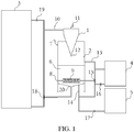
- Fig. 1 is a schematic structural diagram of an ion exchange resin fixed bed counter-current regeneration device according to one or more embodiments of the present invention.
- the corresponding labels in the diagram are: 1, Cyclone separator; 2, Regeneration reactor; 3, Fully mixed resin reactor; 4, Desorption solution storage tank; 5, Regenerant storage tank; 6, Resin bed; 7, Fresh water inlet; 8, Fresh water outlet; 9, Resin filter; 10, Feed inlet; 11, Overflow port; 12, Resin inlet; 13, Regenerant outlet; 14, Regenerant inlet; 15, Desorption solution storage tank water ejector; 16, Desorption solution storage tank circulating pump; 17, Regenerant pump; 18, Fully mixed reactor ejector; 19, Fully mixed resin reactor circulating pump; 20, Resin outlet.
- an ion exchange resin fixed bed counter-current regeneration device in this embodiment comprises a cyclone separator (1), a regeneration reactor (2), a fully mixed resin reactor (3), a desorption solution storage tank (4) and a regenerant storage tank (5).
- the cyclone separator (1) is placed on the top of the regenerative reactor (2), an overflow port (11) is arranged at the top of the cyclone separator (1), the upper part of the cyclone separator (1) is connected to the lower end of the fully mixed resin reactor (3) through a feed inlet (10), the feed inlet (10) comes into contact with the cyclone separator (1) tangentially, and transports the resin and water from the fully mixed resin reactor (3) to the cyclone separator (1) by water pressure, solid-liquid separation is achieved by centrifugal force in the cyclone separator (1).
- the bottom of the cyclone separator (1) is provided with a resin inlet (12) through which the resin enters the regeneration reactor (2) and the remaining water is discharged from the overflow port (11).
- the upper part of the cyclone separator (1) is a cylinder structure
- the lower part is a cone structure
- the cone angle of the cone is 10°which facilitates the flow guidance of the internal material and facilitates the enrichment of the resin.
- the cyclone separator (1) is lined with rubber or other wear-resistant material.
- the upper part and the lower part of the regeneration reactor (2) are also respectively provided with a fresh water inlet (7) and a fresh water outlet (8).
- a resin bed (6) and a resin filter (9) are sequentially arranged from top to bottom in the regeneration reactor (2). The two ends of the resin filter (9) are respectively connected to the fresh water outlet (8) and the desorption solution storage tank (4).
- a resin outlet (20) and a regenerant inlet (14) are arranged at the bottom of the regeneration reactor (2), the resin outlet (20) is connected to the fully mixed resin reactor (3).
- the regenerant inlet (14) is connected to the desorption solution storage tank (4) and the regenerant storage tank (5), in which the regenerant inlet (14) is connected to the regenerant storage tank (5) through the regenerant pump (17).
- One side of the regeneration reactor (2) is also provided with a regenerant outlet (13), which is connected to the desorption solution storage tank (4).
- one side of the full mixed resin reactor 3 in this embodiment is provided with a first circulation pipeline, the feed inlet 10 is connected to the first circulation pipeline, and the upper end of first circulation pipeline Is connected to the upper part of the fully mixed resin reactor (3) through the fully mixed resin reactor circulating pump (19), the lower end of the first circulating pipe is connected to the lower part of the fully mixed resin reactor (3).
- the first circulation pipeline is also provided with the fully mixed resin reactor water ejector 18, and the resin outlet (20) is connected to the fully mixed resin reactor water ejector (18).
- the resin produced in the regeneration reactor (2) is transferred to the fully mixed resin reactor (3) by the fully mixed resin reactor circulating pump (19) and the fully mixed resin reactor water ejector (18), where the circulation setting can backwash or wash counter-currently the resin sedimented on the bottom of the fully mixed resin reactor (3), which can keep the resin in a fluffy state and enhance the recycling or regeneration effect of the resin.
- one side of the desorption solution storage tank (4) is provided with a second circulation pipeline, the regenerant outlet (13) and the regenerant inlet (14) are respectively connected to the second circulation pipeline, the upper end of the second circulation pipeline is connected to the upper part of the desorption solution storage tank (4), the lower end of the second circulation pipeline is connected to the lower part of the desorption solution storage tank (4) through the desorption solution storage tank circulating pump (16).
- the second circulation pipeline is also provided with the desorption solution storage tank water ejector (15), which is connected to one end of the resin filter (9). Through the action of the regenerant pump(17), the regenerant slowly passes from bottom to top through the resin bed 6, and is discharged from the regenerant outlet (13).
- the desorption solution flows out of the bottom of the desorption solution storage tank (4) and flows into the top of the desorption solution storage tank (4) to form an internal circulation.
- a negative pressure is generated at the desorption solution storage tank water ejector (15), the remaining regenerant in the regeneration reactor (2) is drained to the desorption solution storage tank (4) through the resin filter (9).
- the desorption solution in the desorption solution storage tank (4) can be reused.
- the top part of the regeneration reactor (2) has a top open cylinder structure.
- the height-to-diameter ratio of the cylinder does not exceed 3:1, in order to avoid excessive column pressure and prevent the resin from forming clumps under pressure within the regenerating reactor (2), which would have deleterious effects on regeneration.
- the bottom part of the regeneration reactor (2) is an inverted cone structure. The angle between the generatrix of the inverted cone and the horizontal plane is 10° to 15° , which can effectively guide the resin flow.
- the inner wall of the bottom of the regeneration reactor (2) is made of smooth material, further facilitating the resin flow.
- the resin filter (9) is made of four hollow cylinders closed at both ends. Other numbers are possible. The resin filter (9) is radially parallel to the regeneration reactor (2).
- the outside of the resin filter (9) is tightly wound, in the circumferential direction, with a sieve having a diameter slightly smaller than that of the regenerated resin, therefore retaining the resin and passing the water/solution.
- the screen on the sieve can be selected from material such as stainless-steel wire mesh.
- the regenerant outlet (13) is provided with a filter screen, i.e., sieve, the pore size of the filter screen is slightly smaller than the regenerated resin, and the filter screen can also be made from a stainless-steel wire screen.
- the regeneration device of the embodiment comprehensively and systematically regulates the regeneration process of the resin through the coordination and cooperation of the cyclone separator, the regeneration reactor, the fully mixed resin reactor, the desorption solution storage tank and the regenerant storage tank, thereby significantly improves the resin regeneration efficiency, the service longevity of the resin, and the re-use of desorption solution, among many aspects.
- the device and the method are well suited for wide-range and large-scale expansion or adoption.
- Each component of the embodiment relies on and collaborates with other component(s) with precise, efficient, and clear structure distribution that maximizes space saving. As a result, the regeneration process flows smoothly and effortlessly, which greatly facilitates production operation.
- a specific method of use is disclosed as follows:
- a method for using the ion exchange resin fixed bed counter-current regeneration device comprises the following steps:
- the regenerative reactor (2) is a glass fiber steel structure with a diameter of 1.5 meters and a height of 2 meters.
- the cyclone separator (1) has an inner diameter of 250 mm, the cone angle of the lower part of the cyclone separator (1) is 20°, the diameter of the feed inlet (10) is 75 mm, the diameter of the overflow port (11) is 100 mm, and the diameter of the resin inlet (12) is 35 mm.
- the resin filter (9) includes two hollow cylinders with both ends closed. The sieve that tightly wraps around the periphery of the resin filter (9) has a sieve mesh aperture of 150 ⁇ m. The distance between the regenerant outlet (13) and the top of the regeneration reactor (2) is 60cm.
- the equilibrium adsorption amount of the regenerated resin is greater than 95% of the equilibrium adsorption amount of new resin.
- an ion exchange resin fixed bed counter-current regeneration device substantially similar to Example 2, is disclosed.
- the regeneration reactor (2) in this embodiment is a glass steel structure with a diameter of 2.0 meters and a height of 2.5 meters.
- the inner diameter of the cyclone separator (1) is 300mm
- the cone angle of the lower cone of the cyclone separator (1) is 45°
- the diameter of the feed inlet (10) is 50mm
- the diameter of the resin inlet (12) is 38mm.
- the resin filter (9) is 3 hollow cylinders with both ends closed.
- the sieve that tightly wraps around the periphery of the resin filter (9) has a sieve mesh aperture of 150 ⁇ m.
- the distance between the regenerant outlet (13) and the top of the regeneration reactor (2) is 60cm.
- a fresh regenerant (15% by mass of NaCl + 1% by mass of NaOH solution) from the regenerant tank (5) or a desorption solution from the desorption solution storage tank (4) is injected into the regenerating reactor (2) through the effect of the regenerant pump 17.
- the regenerant flows counter-currently and slowly through the resin bed (6) to complete the resin regeneration.
- the counter-current velocity of the regenerant is 4BV/h.
- the equilibrium adsorption amount of the regenerated resin is greater than 98% of the equilibrium adsorption amount of the new resin.
- an ion exchange resin fixed bed counter-current regeneration device substantially similar to Example 2, is disclosed.
- the regenerant in this embodiment is a 26% NaCl solution instead.
- the adsorption equilibrium amount of the regenerated resin is greater than 98% of the adsorption equilibrium amount of the new resin.
- an ion exchange resin fixed bed counter-current regeneration device substantially similar to Example 4, is disclosed.
- the regenerant is reused.
- the desorption solution storage tank (4) Prior to using the device, the desorption solution storage tank (4) is supplemented with NaCl powder to 5%. After the desorption solution was reused four times, the equilibrium adsorption amount of the regenerated resin was greater than 70% of the equilibrium adsorption amount of the new resin. The desorption solution yield was only 1/4 of the traditional regeneration method, and a large amount of salt was saved.
Landscapes
- Chemical & Material Sciences (AREA)
- Organic Chemistry (AREA)
- Chemical Kinetics & Catalysis (AREA)
- Engineering & Computer Science (AREA)
- Life Sciences & Earth Sciences (AREA)
- Hydrology & Water Resources (AREA)
- Environmental & Geological Engineering (AREA)
- Water Supply & Treatment (AREA)
- Analytical Chemistry (AREA)
- Mechanical Engineering (AREA)
- Treatment Of Water By Ion Exchange (AREA)
Claims (10)
- Gegenstrom-Regenerationsvorrichtung mit Festbett-Ionenaustauscherharz (1), umfassend:einen Zyklonabscheider (1);einen Regenerationsreaktor (2);einen Vollmischharzreaktor (3);einen Speichertank (4) für Desorptionslösung; undeinen Speichertank für Regenerationsmittel (5), wobei der Zyklonabscheider (1) oben auf den Regenerationsreaktor (2) aufgesetzt ist, und der obere Teil des Zyklonabscheiders (1) über einen Zuführeinlass (10) mit dem Vollmischharzreaktor (3) verbunden ist, wobei ein Harzeinlass (12) am Boden des Zyklonabscheiders (1) vorgesehen ist, und der obere Teil des Regenerationsreaktors (2) mit einem Frischwassereinlass (7) versehen ist, wobei ein Harzbett (6) und ein Harzfilter (9) nacheinander von oben nach unten innerhalb des Regenerationsreaktors (2) angeordnet sind, wobei zwei Enden des Harzfilters (9) jeweils mit einem Frischwasserauslass (8) verbunden sind, und wobei der Speichertank (4) für Desorptionslösung, ein Harzauslass (20) und ein Regenerationsmitteleinlass (14) am Boden des Regenerationsreaktors (2) vorgesehen sind, wobei der Harzauslass (20) mit dem Vollmischharzreaktor (3) verbunden ist, und der Regenerationsmitteleinlass (14) jeweils mit dem Speichertank (4) für Desorptionslösung und dem Speichertank (5) für Regenerationsmittel verbunden ist, wobei eine Seite des Regenerationsreaktors (2) ebenfalls mit einem Regenerationsmittelauslass (13) versehen ist, der mit dem Desorptionslösungstank (4) verbunden ist.
- Gegenstrom-Regenerationsvorrichtung mit Festbett-Ionenaustauscherharz nach Anspruch 1, ferner umfassend einen Wasserejektor (15) für den Speichertank für Desorptionslösung, vorgesehen an einer Rohrleitung, die den Speichertank (4) für Desorptionslösung und den Harzfilter (9) verbindet.
- Gegenstrom-Regenerationsvorrichtung mit Festbett-Ionenaustauscherharz nach Anspruch 1 oder 2, ferner umfassend einen Wasserejektor (18) für den Vollmischharzreaktor, der an der Rohrleitung angeordnet ist, die den Harzauslass (20) mit dem Vollmischharzreaktor (3) verbindet.
- Gegenstrom-Regenerationsvorrichtung mit Festbett-Ionenaustauscherharz nach Anspruch 1 oder 2, wobei der obere Teil des Zyklonabscheiders (1) eine Zylinderstruktur einnimmt und der untere Teil des Zyklonabscheiders (1) eine Kegelstruktur einnimmt und der Kegelwinkel der Kegelstruktur im Bereich von 10 ° bis 45 ° liegt.
- Gegenstrom-Regenerationsvorrichtung mit Festbett-Ionenaustauscherharz nach Anspruch 4, wobei der Regenerationsreaktor (2) eine oben offene Zylinderstruktur ist, und das Verhältnis von Höhe zu Durchmesser des Zylinders 3: 1 nicht überschreitet.
- Gegenstrom-Regenerationsvorrichtung mit Festbett-Ionenaustauscherharz nach Anspruch 5, wobei der untere Teil des Regenerationsreaktors (2) eine umgekehrte Kegelstruktur ist, und der Winkel zwischen der Erzeugenden der umgekehrten Kegelstruktur und der horizontalen Ebene innerhalb von 10° ∼ 15° liegt.
- Gegenstrom-Regenerationsvorrichtung mit Festbett-Ionenaustauscherharz nach Anspruch 6, wobei der Harzfilter (9) zwei bis vier an beiden Enden geschlossene Hohlzylinder aufweist, wobei der Harzfilter (9) radial parallel zum Regenerationsreaktor (2) ist, und wobei ein Sieb in Umfangsrichtung dicht um die Außenseite des Harzfilters (9) gewickelt ist.
- Gegenstrom-Regenerationsvorrichtung mit Festbett-Ionenaustauscherharz nach Anspruch 7, wobei am Regenerationsmittelauslass (13) ein Filtersieb angeordnet ist und das Filtersieb aus einem Edelstahldrahtgeflecht besteht.
- Verfahren zur Verwendung einer lonenaustauscherharz-Festbett-Gegenstrom-Regenerationsvorrichtung, umfassend die Schritte:Schritt 1: Abgeben eines Gemisches aus adsorptionsgesättigtem Ionenaustauscherharz und Wasser aus einem Vollmischharzreaktor (3) in einen Zyklonabscheider (1), Anreicherung des Harzes, Führen des Harzes in einen Regenerationsreaktor (2), Leiten von Restwasser durch einen Harzfilter (9) und Abgeben des Restwassers durch einen Frischwasserauslass (8);Schritt 2: Injizieren eines Regenerationsmittels aus einem Speichertank für Regenerationsmittel (5) oder einer Desorptionslösung aus einem Speichertank (4) für Desorptionsmittel in den Regenerationsreaktor (2), so dass das Regenerationsmittel im Gegenstrom durch ein Harzbett (6) fließt, um die Harzregeneration zu vervollständigen;Schritt 3: Ablassen der verbleibenden Desorptionslösung im Regenerationsreaktor (2), nachdem die Harzregeneration vervollständigt ist, Einspritzen von Frischwasser in das Harzbett (6) zum Reinigen des Harzes, und Ablassen des Frischwassers durch den Harzfilter (9); undSchritt 4: Abgeben des regenerierten Harzes aus dem Regenerationsreaktor (2) in den Vollmischharzreaktor (3), um den Regenerationsprozess zu vervollständigen.
- Verfahren zur Verwendung einer Gegenstrom-Regenerationsvorrichtung mit Festbett-Ionenaustauscherharz nach Anspruch 9, wobei die Kontaktzeit zwischen dem Harzbett (6) und dem Regenerationsmittel 10 bis 30 Minuten beträgt.
Applications Claiming Priority (1)
| Application Number | Priority Date | Filing Date | Title |
|---|---|---|---|
| CN201710177921.9A CN106881159B (zh) | 2017-03-23 | 2017-03-23 | 一种离子交换树脂固定床逆流再生装置及其使用方法 |
Publications (2)
| Publication Number | Publication Date |
|---|---|
| EP3378558A1 EP3378558A1 (de) | 2018-09-26 |
| EP3378558B1 true EP3378558B1 (de) | 2019-09-25 |
Family
ID=59182349
Family Applications (1)
| Application Number | Title | Priority Date | Filing Date |
|---|---|---|---|
| EP18160832.4A Active EP3378558B1 (de) | 2017-03-23 | 2018-03-08 | Festbett-gegenstrom-regenerationsvorrichtung aus ionenaustauscherharz und anwendungsverfahren einer festbett-gegenstrom-regenerationsvorrichtung |
Country Status (4)
| Country | Link |
|---|---|
| US (1) | US11103865B2 (de) |
| EP (1) | EP3378558B1 (de) |
| CN (1) | CN106881159B (de) |
| WO (1) | WO2018171068A1 (de) |
Families Citing this family (5)
| Publication number | Priority date | Publication date | Assignee | Title |
|---|---|---|---|---|
| CN106881159B (zh) * | 2017-03-23 | 2018-08-24 | 南京大学 | 一种离子交换树脂固定床逆流再生装置及其使用方法 |
| CN109967135A (zh) * | 2019-03-18 | 2019-07-05 | 南京利福达膜科技有限公司 | 一种工业级仓内高效树脂柱及工作仓 |
| CN112264112A (zh) * | 2020-09-29 | 2021-01-26 | 中信建设有限责任公司 | 一种水处理用树脂流化床系统 |
| CN116177572A (zh) * | 2022-12-05 | 2023-05-30 | 四川国理锂材料有限公司 | 一种硫酸锂溶液的除钙生产工艺 |
| CN117943135A (zh) * | 2024-01-31 | 2024-04-30 | 中冶华天南京工程技术有限公司 | 一种异向流树脂再生系统及方法 |
Family Cites Families (11)
| Publication number | Priority date | Publication date | Assignee | Title |
|---|---|---|---|---|
| US2563006A (en) * | 1946-11-02 | 1951-08-07 | Sharples Corp | Treatment of liquids with ion exchange materials |
| US3455819A (en) * | 1968-04-01 | 1969-07-15 | Crane Co | Method for scrubbing ion exchange resins |
| US4280904A (en) | 1978-04-12 | 1981-07-28 | American Petro Mart, Inc. | High capacity folded moving bed ion exchange apparatus and method for treating phosphoric acid |
| CN85100138B (zh) * | 1985-04-01 | 1988-08-17 | 清华大学 | 用二氧化碳再生放射性离子交换树脂的方法 |
| CN1038482C (zh) * | 1989-03-09 | 1998-05-27 | 邹萃林 | 纯水制备中离子交换树脂的再生方法 |
| CN2362838Y (zh) | 1998-11-11 | 2000-02-09 | 宜兴市江南水工设备厂 | 树脂再生废液处理装置 |
| CN2684923Y (zh) * | 2002-10-24 | 2005-03-16 | 北京市双峰纯水设备厂 | 离子交换树脂再生装置 |
| DE202008011162U1 (de) | 2008-08-21 | 2008-10-30 | Blum, Holger | Abwasserreinigungsvorrichtung |
| CN102489347B (zh) | 2011-12-19 | 2014-05-14 | 南京大学 | 一种粉体树脂脱附再生反应器 |
| CN104003478B (zh) | 2014-06-16 | 2015-12-02 | 成都丽雅纤维股份有限公司 | 离子交换树脂的体外逆流再生工艺 |
| CN106881159B (zh) | 2017-03-23 | 2018-08-24 | 南京大学 | 一种离子交换树脂固定床逆流再生装置及其使用方法 |
-
2017
- 2017-03-23 CN CN201710177921.9A patent/CN106881159B/zh active Active
- 2017-06-28 WO PCT/CN2017/090445 patent/WO2018171068A1/zh not_active Ceased
- 2017-06-28 US US15/774,966 patent/US11103865B2/en active Active
-
2018
- 2018-03-08 EP EP18160832.4A patent/EP3378558B1/de active Active
Non-Patent Citations (1)
| Title |
|---|
| None * |
Also Published As
| Publication number | Publication date |
|---|---|
| CN106881159A (zh) | 2017-06-23 |
| US11103865B2 (en) | 2021-08-31 |
| WO2018171068A1 (zh) | 2018-09-27 |
| US20210162397A1 (en) | 2021-06-03 |
| CN106881159B (zh) | 2018-08-24 |
| EP3378558A1 (de) | 2018-09-26 |
Similar Documents
| Publication | Publication Date | Title |
|---|---|---|
| EP3378558A1 (de) | Festbett-gegenstrom-regenerationsvorrichtung aus ionenaustauscherharz und anwendungsverfahren einer festbett-gegenstrom-regenerationsvorrichtung | |
| CN102992433B (zh) | 一种萘系染料中间体生产废水萃取回收方法 | |
| CN202688095U (zh) | 一种用于印染废水处理的高效生物反应器 | |
| US12172918B2 (en) | Domestic sewage treatment system | |
| CN108658225B (zh) | 一种农村污水强化复合厌氧处理装置及处理方法 | |
| CN106315843A (zh) | 一种低温条件下高效截留厌氧铵氧化菌的反应器 | |
| CN104888984A (zh) | 一种磁旋流分离器及分离装置和方法 | |
| CN205710086U (zh) | 一种mbr一体化污水处理设备 | |
| CN102489347B (zh) | 一种粉体树脂脱附再生反应器 | |
| CN105384230B (zh) | 一种纤维素废水预处理装置及应用 | |
| CN213680968U (zh) | 一种用于酸性液再生连续循环的废酸处理系统 | |
| CN212700660U (zh) | 用于吸附法卤水提锂的设备 | |
| CN204447403U (zh) | 一种活性炭连续逆流吸附净化装置 | |
| CN208532380U (zh) | 一种改进型ic厌氧反应器 | |
| CN214261916U (zh) | 一种水处理用树脂流化床系统 | |
| CN109279739A (zh) | 一种液固双床吸附脱酚处理化工污水的方法及其专用系统 | |
| KR20140022173A (ko) | 분뇨처리장치 | |
| CN209024357U (zh) | 一种有机废水处理设备 | |
| CN209997306U (zh) | 一种吸附分金装置 | |
| CN115057530A (zh) | 一种无三相分离器的厌氧反应器 | |
| CN113426433B (zh) | 一种磁性树脂的高效再生装置及方法 | |
| CN219174381U (zh) | 一种二苯乙烷含苯废水处理回用装置 | |
| CN209210531U (zh) | 一种循环中水回用水池 | |
| CN223980246U (zh) | 脱水装置及水循环系统 | |
| CN208022934U (zh) | 一种从吐氏酸废水中提取吐氏酸的提取系统 |
Legal Events
| Date | Code | Title | Description |
|---|---|---|---|
| PUAI | Public reference made under article 153(3) epc to a published international application that has entered the european phase |
Free format text: ORIGINAL CODE: 0009012 |
|
| STAA | Information on the status of an ep patent application or granted ep patent |
Free format text: STATUS: REQUEST FOR EXAMINATION WAS MADE |
|
| 17P | Request for examination filed |
Effective date: 20180323 |
|
| AK | Designated contracting states |
Kind code of ref document: A1 Designated state(s): AL AT BE BG CH CY CZ DE DK EE ES FI FR GB GR HR HU IE IS IT LI LT LU LV MC MK MT NL NO PL PT RO RS SE SI SK SM TR |
|
| AX | Request for extension of the european patent |
Extension state: BA ME |
|
| STAA | Information on the status of an ep patent application or granted ep patent |
Free format text: STATUS: EXAMINATION IS IN PROGRESS |
|
| 17Q | First examination report despatched |
Effective date: 20181012 |
|
| GRAP | Despatch of communication of intention to grant a patent |
Free format text: ORIGINAL CODE: EPIDOSNIGR1 |
|
| STAA | Information on the status of an ep patent application or granted ep patent |
Free format text: STATUS: GRANT OF PATENT IS INTENDED |
|
| RIC1 | Information provided on ipc code assigned before grant |
Ipc: B01J 49/90 20170101ALI20190329BHEP Ipc: B01J 49/60 20170101ALI20190329BHEP Ipc: B01J 49/05 20170101AFI20190329BHEP |
|
| INTG | Intention to grant announced |
Effective date: 20190502 |
|
| GRAS | Grant fee paid |
Free format text: ORIGINAL CODE: EPIDOSNIGR3 |
|
| GRAA | (expected) grant |
Free format text: ORIGINAL CODE: 0009210 |
|
| STAA | Information on the status of an ep patent application or granted ep patent |
Free format text: STATUS: THE PATENT HAS BEEN GRANTED |
|
| AK | Designated contracting states |
Kind code of ref document: B1 Designated state(s): AL AT BE BG CH CY CZ DE DK EE ES FI FR GB GR HR HU IE IS IT LI LT LU LV MC MK MT NL NO PL PT RO RS SE SI SK SM TR |
|
| REG | Reference to a national code |
Ref country code: GB Ref legal event code: FG4D |
|
| REG | Reference to a national code |
Ref country code: CH Ref legal event code: EP |
|
| REG | Reference to a national code |
Ref country code: AT Ref legal event code: REF Ref document number: 1183279 Country of ref document: AT Kind code of ref document: T Effective date: 20191015 |
|
| REG | Reference to a national code |
Ref country code: IE Ref legal event code: FG4D |
|
| REG | Reference to a national code |
Ref country code: DE Ref legal event code: R096 Ref document number: 602018000715 Country of ref document: DE |
|
| REG | Reference to a national code |
Ref country code: NL Ref legal event code: MP Effective date: 20190925 |
|
| PG25 | Lapsed in a contracting state [announced via postgrant information from national office to epo] |
Ref country code: SE Free format text: LAPSE BECAUSE OF FAILURE TO SUBMIT A TRANSLATION OF THE DESCRIPTION OR TO PAY THE FEE WITHIN THE PRESCRIBED TIME-LIMIT Effective date: 20190925 Ref country code: HR Free format text: LAPSE BECAUSE OF FAILURE TO SUBMIT A TRANSLATION OF THE DESCRIPTION OR TO PAY THE FEE WITHIN THE PRESCRIBED TIME-LIMIT Effective date: 20190925 Ref country code: BG Free format text: LAPSE BECAUSE OF FAILURE TO SUBMIT A TRANSLATION OF THE DESCRIPTION OR TO PAY THE FEE WITHIN THE PRESCRIBED TIME-LIMIT Effective date: 20191225 Ref country code: LT Free format text: LAPSE BECAUSE OF FAILURE TO SUBMIT A TRANSLATION OF THE DESCRIPTION OR TO PAY THE FEE WITHIN THE PRESCRIBED TIME-LIMIT Effective date: 20190925 Ref country code: FI Free format text: LAPSE BECAUSE OF FAILURE TO SUBMIT A TRANSLATION OF THE DESCRIPTION OR TO PAY THE FEE WITHIN THE PRESCRIBED TIME-LIMIT Effective date: 20190925 Ref country code: NO Free format text: LAPSE BECAUSE OF FAILURE TO SUBMIT A TRANSLATION OF THE DESCRIPTION OR TO PAY THE FEE WITHIN THE PRESCRIBED TIME-LIMIT Effective date: 20191225 |
|
| REG | Reference to a national code |
Ref country code: LT Ref legal event code: MG4D |
|
| PG25 | Lapsed in a contracting state [announced via postgrant information from national office to epo] |
Ref country code: GR Free format text: LAPSE BECAUSE OF FAILURE TO SUBMIT A TRANSLATION OF THE DESCRIPTION OR TO PAY THE FEE WITHIN THE PRESCRIBED TIME-LIMIT Effective date: 20191226 Ref country code: RS Free format text: LAPSE BECAUSE OF FAILURE TO SUBMIT A TRANSLATION OF THE DESCRIPTION OR TO PAY THE FEE WITHIN THE PRESCRIBED TIME-LIMIT Effective date: 20190925 Ref country code: LV Free format text: LAPSE BECAUSE OF FAILURE TO SUBMIT A TRANSLATION OF THE DESCRIPTION OR TO PAY THE FEE WITHIN THE PRESCRIBED TIME-LIMIT Effective date: 20190925 |
|
| REG | Reference to a national code |
Ref country code: AT Ref legal event code: MK05 Ref document number: 1183279 Country of ref document: AT Kind code of ref document: T Effective date: 20190925 |
|
| PG25 | Lapsed in a contracting state [announced via postgrant information from national office to epo] |
Ref country code: PT Free format text: LAPSE BECAUSE OF FAILURE TO SUBMIT A TRANSLATION OF THE DESCRIPTION OR TO PAY THE FEE WITHIN THE PRESCRIBED TIME-LIMIT Effective date: 20200127 Ref country code: AL Free format text: LAPSE BECAUSE OF FAILURE TO SUBMIT A TRANSLATION OF THE DESCRIPTION OR TO PAY THE FEE WITHIN THE PRESCRIBED TIME-LIMIT Effective date: 20190925 Ref country code: ES Free format text: LAPSE BECAUSE OF FAILURE TO SUBMIT A TRANSLATION OF THE DESCRIPTION OR TO PAY THE FEE WITHIN THE PRESCRIBED TIME-LIMIT Effective date: 20190925 Ref country code: IT Free format text: LAPSE BECAUSE OF FAILURE TO SUBMIT A TRANSLATION OF THE DESCRIPTION OR TO PAY THE FEE WITHIN THE PRESCRIBED TIME-LIMIT Effective date: 20190925 Ref country code: RO Free format text: LAPSE BECAUSE OF FAILURE TO SUBMIT A TRANSLATION OF THE DESCRIPTION OR TO PAY THE FEE WITHIN THE PRESCRIBED TIME-LIMIT Effective date: 20190925 Ref country code: AT Free format text: LAPSE BECAUSE OF FAILURE TO SUBMIT A TRANSLATION OF THE DESCRIPTION OR TO PAY THE FEE WITHIN THE PRESCRIBED TIME-LIMIT Effective date: 20190925 Ref country code: EE Free format text: LAPSE BECAUSE OF FAILURE TO SUBMIT A TRANSLATION OF THE DESCRIPTION OR TO PAY THE FEE WITHIN THE PRESCRIBED TIME-LIMIT Effective date: 20190925 Ref country code: PL Free format text: LAPSE BECAUSE OF FAILURE TO SUBMIT A TRANSLATION OF THE DESCRIPTION OR TO PAY THE FEE WITHIN THE PRESCRIBED TIME-LIMIT Effective date: 20190925 Ref country code: NL Free format text: LAPSE BECAUSE OF FAILURE TO SUBMIT A TRANSLATION OF THE DESCRIPTION OR TO PAY THE FEE WITHIN THE PRESCRIBED TIME-LIMIT Effective date: 20190925 |
|
| PG25 | Lapsed in a contracting state [announced via postgrant information from national office to epo] |
Ref country code: SM Free format text: LAPSE BECAUSE OF FAILURE TO SUBMIT A TRANSLATION OF THE DESCRIPTION OR TO PAY THE FEE WITHIN THE PRESCRIBED TIME-LIMIT Effective date: 20190925 Ref country code: CZ Free format text: LAPSE BECAUSE OF FAILURE TO SUBMIT A TRANSLATION OF THE DESCRIPTION OR TO PAY THE FEE WITHIN THE PRESCRIBED TIME-LIMIT Effective date: 20190925 Ref country code: IS Free format text: LAPSE BECAUSE OF FAILURE TO SUBMIT A TRANSLATION OF THE DESCRIPTION OR TO PAY THE FEE WITHIN THE PRESCRIBED TIME-LIMIT Effective date: 20200224 Ref country code: SK Free format text: LAPSE BECAUSE OF FAILURE TO SUBMIT A TRANSLATION OF THE DESCRIPTION OR TO PAY THE FEE WITHIN THE PRESCRIBED TIME-LIMIT Effective date: 20190925 |
|
| REG | Reference to a national code |
Ref country code: DE Ref legal event code: R097 Ref document number: 602018000715 Country of ref document: DE |
|
| PG2D | Information on lapse in contracting state deleted |
Ref country code: IS |
|
| PG25 | Lapsed in a contracting state [announced via postgrant information from national office to epo] |
Ref country code: DK Free format text: LAPSE BECAUSE OF FAILURE TO SUBMIT A TRANSLATION OF THE DESCRIPTION OR TO PAY THE FEE WITHIN THE PRESCRIBED TIME-LIMIT Effective date: 20190925 Ref country code: IS Free format text: LAPSE BECAUSE OF FAILURE TO SUBMIT A TRANSLATION OF THE DESCRIPTION OR TO PAY THE FEE WITHIN THE PRESCRIBED TIME-LIMIT Effective date: 20200126 |
|
| PLBE | No opposition filed within time limit |
Free format text: ORIGINAL CODE: 0009261 |
|
| STAA | Information on the status of an ep patent application or granted ep patent |
Free format text: STATUS: NO OPPOSITION FILED WITHIN TIME LIMIT |
|
| 26N | No opposition filed |
Effective date: 20200626 |
|
| PG25 | Lapsed in a contracting state [announced via postgrant information from national office to epo] |
Ref country code: MC Free format text: LAPSE BECAUSE OF FAILURE TO SUBMIT A TRANSLATION OF THE DESCRIPTION OR TO PAY THE FEE WITHIN THE PRESCRIBED TIME-LIMIT Effective date: 20190925 |
|
| PG25 | Lapsed in a contracting state [announced via postgrant information from national office to epo] |
Ref country code: SI Free format text: LAPSE BECAUSE OF FAILURE TO SUBMIT A TRANSLATION OF THE DESCRIPTION OR TO PAY THE FEE WITHIN THE PRESCRIBED TIME-LIMIT Effective date: 20190925 |
|
| REG | Reference to a national code |
Ref country code: BE Ref legal event code: MM Effective date: 20200331 |
|
| PG25 | Lapsed in a contracting state [announced via postgrant information from national office to epo] |
Ref country code: LU Free format text: LAPSE BECAUSE OF NON-PAYMENT OF DUE FEES Effective date: 20200308 |
|
| PG25 | Lapsed in a contracting state [announced via postgrant information from national office to epo] |
Ref country code: IE Free format text: LAPSE BECAUSE OF NON-PAYMENT OF DUE FEES Effective date: 20200308 |
|
| PG25 | Lapsed in a contracting state [announced via postgrant information from national office to epo] |
Ref country code: BE Free format text: LAPSE BECAUSE OF NON-PAYMENT OF DUE FEES Effective date: 20200331 |
|
| REG | Reference to a national code |
Ref country code: CH Ref legal event code: PL |
|
| PG25 | Lapsed in a contracting state [announced via postgrant information from national office to epo] |
Ref country code: LI Free format text: LAPSE BECAUSE OF NON-PAYMENT OF DUE FEES Effective date: 20210331 Ref country code: CH Free format text: LAPSE BECAUSE OF NON-PAYMENT OF DUE FEES Effective date: 20210331 |
|
| PG25 | Lapsed in a contracting state [announced via postgrant information from national office to epo] |
Ref country code: TR Free format text: LAPSE BECAUSE OF FAILURE TO SUBMIT A TRANSLATION OF THE DESCRIPTION OR TO PAY THE FEE WITHIN THE PRESCRIBED TIME-LIMIT Effective date: 20190925 Ref country code: MT Free format text: LAPSE BECAUSE OF FAILURE TO SUBMIT A TRANSLATION OF THE DESCRIPTION OR TO PAY THE FEE WITHIN THE PRESCRIBED TIME-LIMIT Effective date: 20190925 Ref country code: CY Free format text: LAPSE BECAUSE OF FAILURE TO SUBMIT A TRANSLATION OF THE DESCRIPTION OR TO PAY THE FEE WITHIN THE PRESCRIBED TIME-LIMIT Effective date: 20190925 |
|
| PG25 | Lapsed in a contracting state [announced via postgrant information from national office to epo] |
Ref country code: MK Free format text: LAPSE BECAUSE OF FAILURE TO SUBMIT A TRANSLATION OF THE DESCRIPTION OR TO PAY THE FEE WITHIN THE PRESCRIBED TIME-LIMIT Effective date: 20190925 |
|
| PGFP | Annual fee paid to national office [announced via postgrant information from national office to epo] |
Ref country code: GB Payment date: 20260323 Year of fee payment: 9 |
|
| PGFP | Annual fee paid to national office [announced via postgrant information from national office to epo] |
Ref country code: DE Payment date: 20260313 Year of fee payment: 9 |
|
| PGFP | Annual fee paid to national office [announced via postgrant information from national office to epo] |
Ref country code: FR Payment date: 20260330 Year of fee payment: 9 |