EP3378417B1 - Vorrichtung für minimalinvasive chirurgie zur knochenentnahme - Google Patents
Vorrichtung für minimalinvasive chirurgie zur knochenentnahme Download PDFInfo
- Publication number
- EP3378417B1 EP3378417B1 EP17182534.2A EP17182534A EP3378417B1 EP 3378417 B1 EP3378417 B1 EP 3378417B1 EP 17182534 A EP17182534 A EP 17182534A EP 3378417 B1 EP3378417 B1 EP 3378417B1
- Authority
- EP
- European Patent Office
- Prior art keywords
- head
- minimally invasive
- bone
- sleeve
- spiral
- Prior art date
- Legal status (The legal status is an assumption and is not a legal conclusion. Google has not performed a legal analysis and makes no representation as to the accuracy of the status listed.)
- Active
Links
Images
Classifications
-
- A—HUMAN NECESSITIES
- A61—MEDICAL OR VETERINARY SCIENCE; HYGIENE
- A61B—DIAGNOSIS; SURGERY; IDENTIFICATION
- A61B17/00—Surgical instruments, devices or methods
- A61B17/16—Instruments for performing osteoclasis; Drills or chisels for bones; Trepans
- A61B17/1635—Instruments for performing osteoclasis; Drills or chisels for bones; Trepans for grafts, harvesting or transplants
-
- A—HUMAN NECESSITIES
- A61—MEDICAL OR VETERINARY SCIENCE; HYGIENE
- A61B—DIAGNOSIS; SURGERY; IDENTIFICATION
- A61B17/00—Surgical instruments, devices or methods
- A61B17/16—Instruments for performing osteoclasis; Drills or chisels for bones; Trepans
-
- A—HUMAN NECESSITIES
- A61—MEDICAL OR VETERINARY SCIENCE; HYGIENE
- A61B—DIAGNOSIS; SURGERY; IDENTIFICATION
- A61B17/00—Surgical instruments, devices or methods
- A61B17/00234—Surgical instruments, devices or methods for minimally invasive surgery
-
- A—HUMAN NECESSITIES
- A61—MEDICAL OR VETERINARY SCIENCE; HYGIENE
- A61B—DIAGNOSIS; SURGERY; IDENTIFICATION
- A61B17/00—Surgical instruments, devices or methods
- A61B17/16—Instruments for performing osteoclasis; Drills or chisels for bones; Trepans
- A61B17/1604—Chisels; Rongeurs; Punches; Stamps
-
- A—HUMAN NECESSITIES
- A61—MEDICAL OR VETERINARY SCIENCE; HYGIENE
- A61B—DIAGNOSIS; SURGERY; IDENTIFICATION
- A61B17/00—Surgical instruments, devices or methods
- A61B17/16—Instruments for performing osteoclasis; Drills or chisels for bones; Trepans
- A61B17/1613—Component parts
- A61B17/1615—Drill bits, i.e. rotating tools extending from a handpiece to contact the worked material
- A61B17/1617—Drill bits, i.e. rotating tools extending from a handpiece to contact the worked material with mobile or detachable parts
-
- A—HUMAN NECESSITIES
- A61—MEDICAL OR VETERINARY SCIENCE; HYGIENE
- A61B—DIAGNOSIS; SURGERY; IDENTIFICATION
- A61B17/00—Surgical instruments, devices or methods
- A61B17/16—Instruments for performing osteoclasis; Drills or chisels for bones; Trepans
- A61B17/1613—Component parts
- A61B17/1622—Drill handpieces
- A61B17/1624—Drive mechanisms therefor
-
- A—HUMAN NECESSITIES
- A61—MEDICAL OR VETERINARY SCIENCE; HYGIENE
- A61B—DIAGNOSIS; SURGERY; IDENTIFICATION
- A61B17/00—Surgical instruments, devices or methods
- A61B17/16—Instruments for performing osteoclasis; Drills or chisels for bones; Trepans
- A61B17/1613—Component parts
- A61B17/1626—Control means; Display units
-
- A—HUMAN NECESSITIES
- A61—MEDICAL OR VETERINARY SCIENCE; HYGIENE
- A61B—DIAGNOSIS; SURGERY; IDENTIFICATION
- A61B17/00—Surgical instruments, devices or methods
- A61B17/16—Instruments for performing osteoclasis; Drills or chisels for bones; Trepans
- A61B17/1613—Component parts
- A61B17/1628—Motors; Power supplies
-
- A—HUMAN NECESSITIES
- A61—MEDICAL OR VETERINARY SCIENCE; HYGIENE
- A61B—DIAGNOSIS; SURGERY; IDENTIFICATION
- A61B17/00—Surgical instruments, devices or methods
- A61B17/16—Instruments for performing osteoclasis; Drills or chisels for bones; Trepans
- A61B17/1613—Component parts
- A61B17/1633—Sleeves, i.e. non-rotating parts surrounding the bit shaft, e.g. the sleeve forming a single unit with the bit shaft
-
- A—HUMAN NECESSITIES
- A61—MEDICAL OR VETERINARY SCIENCE; HYGIENE
- A61B—DIAGNOSIS; SURGERY; IDENTIFICATION
- A61B17/00—Surgical instruments, devices or methods
- A61B2017/00017—Electrical control of surgical instruments
-
- A—HUMAN NECESSITIES
- A61—MEDICAL OR VETERINARY SCIENCE; HYGIENE
- A61B—DIAGNOSIS; SURGERY; IDENTIFICATION
- A61B17/00—Surgical instruments, devices or methods
- A61B17/00234—Surgical instruments, devices or methods for minimally invasive surgery
- A61B2017/00238—Type of minimally invasive operation
-
- A—HUMAN NECESSITIES
- A61—MEDICAL OR VETERINARY SCIENCE; HYGIENE
- A61B—DIAGNOSIS; SURGERY; IDENTIFICATION
- A61B17/00—Surgical instruments, devices or methods
- A61B2017/00367—Details of actuation of instruments, e.g. relations between pushing buttons, or the like, and activation of the tool, working tip, or the like
- A61B2017/00398—Details of actuation of instruments, e.g. relations between pushing buttons, or the like, and activation of the tool, working tip, or the like using powered actuators, e.g. stepper motors, solenoids
-
- A—HUMAN NECESSITIES
- A61—MEDICAL OR VETERINARY SCIENCE; HYGIENE
- A61B—DIAGNOSIS; SURGERY; IDENTIFICATION
- A61B17/00—Surgical instruments, devices or methods
- A61B2017/00477—Coupling
-
- A—HUMAN NECESSITIES
- A61—MEDICAL OR VETERINARY SCIENCE; HYGIENE
- A61B—DIAGNOSIS; SURGERY; IDENTIFICATION
- A61B17/00—Surgical instruments, devices or methods
- A61B2017/00969—Surgical instruments, devices or methods used for transplantation
-
- A—HUMAN NECESSITIES
- A61—MEDICAL OR VETERINARY SCIENCE; HYGIENE
- A61B—DIAGNOSIS; SURGERY; IDENTIFICATION
- A61B17/00—Surgical instruments, devices or methods
- A61B17/16—Instruments for performing osteoclasis; Drills or chisels for bones; Trepans
- A61B2017/1602—Mills
-
- A—HUMAN NECESSITIES
- A61—MEDICAL OR VETERINARY SCIENCE; HYGIENE
- A61B—DIAGNOSIS; SURGERY; IDENTIFICATION
- A61B90/00—Instruments, implements or accessories specially adapted for surgery or diagnosis and not covered by any of the groups A61B1/00 - A61B50/00, e.g. for luxation treatment or for protecting wound edges
- A61B90/03—Automatic limiting or abutting means, e.g. for safety
- A61B2090/032—Automatic limiting or abutting means, e.g. for safety pressure limiting, e.g. hydrostatic
-
- A—HUMAN NECESSITIES
- A61—MEDICAL OR VETERINARY SCIENCE; HYGIENE
- A61B—DIAGNOSIS; SURGERY; IDENTIFICATION
- A61B90/00—Instruments, implements or accessories specially adapted for surgery or diagnosis and not covered by any of the groups A61B1/00 - A61B50/00, e.g. for luxation treatment or for protecting wound edges
- A61B90/03—Automatic limiting or abutting means, e.g. for safety
- A61B2090/033—Abutting means, stops, e.g. abutting on tissue or skin
- A61B2090/034—Abutting means, stops, e.g. abutting on tissue or skin abutting on parts of the device itself
- A61B2090/035—Abutting means, stops, e.g. abutting on tissue or skin abutting on parts of the device itself preventing further rotation
-
- A—HUMAN NECESSITIES
- A61—MEDICAL OR VETERINARY SCIENCE; HYGIENE
- A61B—DIAGNOSIS; SURGERY; IDENTIFICATION
- A61B90/00—Instruments, implements or accessories specially adapted for surgery or diagnosis and not covered by any of the groups A61B1/00 - A61B50/00, e.g. for luxation treatment or for protecting wound edges
- A61B90/03—Automatic limiting or abutting means, e.g. for safety
- A61B2090/033—Abutting means, stops, e.g. abutting on tissue or skin
- A61B2090/036—Abutting means, stops, e.g. abutting on tissue or skin abutting on tissue or skin
-
- A—HUMAN NECESSITIES
- A61—MEDICAL OR VETERINARY SCIENCE; HYGIENE
- A61B—DIAGNOSIS; SURGERY; IDENTIFICATION
- A61B90/00—Instruments, implements or accessories specially adapted for surgery or diagnosis and not covered by any of the groups A61B1/00 - A61B50/00, e.g. for luxation treatment or for protecting wound edges
- A61B90/06—Measuring instruments not otherwise provided for
- A61B2090/064—Measuring instruments not otherwise provided for for measuring force, pressure or mechanical tension
Definitions
- This invention relates to a piece of medical equipment and, more particularly, relates to a minimally invasive electrical (or pneumatic) bone surgery device for cutting (grinding) bone tissue and orientedly conveying the cancellous bone particles which are cut off or grinded off.
- Bone grafting is a surgical procedure that transplants bone tissue to the bone defect part needing to be strengthened or fused inside a patient, commonly used in bone defects, nonunion of fractures, cavity filling after curettage due to bone diseases or bone tumors, or fusion of spine and joints, etc.
- Clinical autogenous bone grafting has many advantages, such as good histocompatibility, no graft rejection reaction, and strong osteoinduction and so on, which has a good effect on promoting the bone fusion.
- the grafting part commonly used in the autogenous bone graft includes the part of ilium, tibia, upper fibula, rib, etc.
- Autogenous bone graft means taking down the sclerotin of the corresponding parts in the patient's own body and then transplanting to the bone defect site of the patient after processing. Take autogenous iliac bone graft for example.
- the prior art usually needs an incision of skin and soft tissue in a length up to several centimeters and a wider subperiosteal dissection, and then a widow is made on the ilium by an osteotome or the ilium is directly chiseled.
- a material removal instrument may include a cannula and a rotation mechanism.
- the cannula may include a cannula bore and a cannula opening at a distal end of the cannula.
- the cannula opening may provide access to the cannula bore.
- the rotation mechanism may be disposed at least partially within the cannula.
- the rotation mechanism may include an elongated shaft and a thread extended from a portion of the elongated shaft. The thread may be used for dislocating material from a target area. At least a portion of the rotation mechanism may extend from the cannula opening. The rotation mechanism may be rotated within the cannula to cause the thread to impact and dislocate material from the target area.
- devices for minimally invasive bone harvesting surgery include those disclosed in US2014/180321A1 , US2005/203527A1 , US2012/209273A1 , and US2011/112563A1 .
- this invention provides a device for minimally invasive bone harvesting surgery, which only needs a very tiny skin incision and tiny bone window (of several millimeters in diameter), and bone fragments are cut (ground) from cancellous bone and then conveyed through a screw thread channel, which realizes oriented conveying of the cut or ground bone, easy operation, and quick surgery operation, thereby greatly reducing the harm to the patient caused during surgery, reducing the occurrence of the sequelea, and improving the safety of the surgery.
- This invention provides a device for minimally invasive bone harvesting surgery, including a cutter, a sleeve, and a drive control system for driving and controlling the cutter to work.
- the cutter includes a head and a spiral conveying portion; an external screw thread is disposed on a surface of the spiral conveying portion, the sleeve is sleeved on the cutter, the head and at least a part of the external screw thread of the surface of the spiral conveying portion are exposed from the sleeve; and a spiral angle of the spiral conveying portion ranges from 10° to 89°, and the external screw thread of the spiral conveying portion is provided with a plurality of spiral blades, and a major diameter of a first spiral blade of the spiral conveying portion close to the head is less than that of other spiral blades.
- the shape of the head in the invention may be a sphere, ellipsoid, umbrella, hemisphere, semi-ellipsoid, hemisphere+cylinder, semi-ellipsoid+cylinder, taper, or cylinder, and the head may be any of the head whose contact surface in contact with bone is a blunt contact surface.
- the head may be a blunt end which is not edged.
- a front end of the spiral conveying portion may be utilized to cut the bone tissue.
- the surface of the not edged head may be smooth or matte.
- the head may be provided with a cutting edge, and the center of an end of the head may be a blunt surface.
- the head may be provided with a cutting edge, and the cutting edge may be a shallow cutting edge or a non-sharp cutting edge.
- the pitch of the spiral conveying portion may be 1-30 mm.
- the screw thread of the front end of the spiral conveying portion can be described as having a certain taper. Therefore, it can be ensured that during the cutting process of the bone harvesting device, the diameter of the screw thread of the front end in contact with the cortical bone may be relatively small, which makes the bone harvesting device can protect the cortical bone from being damaged by cutting during the bone harvesting process.
- the diameter of the cross section of the sleeve may gradually increase from the position of the head along a direction away from the head.
- the sleeve may be a straight tube, that is, the diameter of the cross section of the sleeve is unchanged from the position of the head along the direction away from the head.
- an edge of a front end surface of the sleeve may be rounded or chamfered.
- the sleeve may be divided into two parts, which are the first part and the second part, wherein the first part may be close to the head, and the second part may be away from the head; the diameter of the cross section of the second part may be larger than that of the first part; and a depth limiting safety step may be disposed at the junction of the second part and the first part of the sleeve.
- the diameter of the cross section of the sleeve may gradually increase from the position of the head along a direction away from the head; a front end surface of the sleeve may be provided with a chamfer or the front end surface may be provided as a slope, and an edge of the front end surface of the sleeve may retract backward, or a thickness of the edge may gradually increase backward.
- the device for minimally invasive bone harvesting surgery may have a pressure limiting safety device.
- the pressure limiting safety device may be a spring, and when the pressure of a front end of the head exceeds or is less than a set range, the spring may be compressed or released to control a motor to stop rotating.
- the pressure limiting safety device may be a current detection device through which a motor is controlled to stop rotating by detecting a current of the motor when the current exceeds or falls below a set range.
- the pressure limiting safety device may be a pressure sensor, and when the pressure of the front end of the head is exceeds or is less than a set range, the motor may be controlled to stop rotating.
- the basic work principle for the device for minimally invasive bone harvesting surgery the cutter is driven by the motor to spin into the cancellous bone, such as the ilium, the end of the tibia and so on, cuts (grinds) the cancellous bone and then conveys the bone through the spiral conveying portion of the cutter, thereby achieving oriented and quick conveying of the solid content (bone particles).
- a minimally invasive incision is made in the skin of the surgical spot, such as the ilium, two ends of the tibia and so on, next an opening is made at the cortical bone of the surgical spot by a puncture hole opener (or a drill bit), and then the device for minimally invasive bone harvesting surgery in the invention is stretched into the opening.
- the device for minimally invasive bone harvesting surgery is turned on, the cutter driven by the electric (or pneumatic) motor cuts (or grinds) the bone tissue, and the cut granular or muddy bone is rapidly and orientedly conveyed through the spiral conveying portion connected behind the head.
- the device for minimally invasive bone harvesting surgery is turned off, and the head is pulled out.
- the cut granular or muddy bone conveyed orientedly can be collected in different methods for the autologous bone transplant of the patient.
- Using the sleeve and the head in a small diameter of the invention can cut (or grind) the cancellous bone under a minimally invasive incision, which leads to a tiny operation wound and a good operation result.
- the head of the device for minimally invasive bone harvesting surgery is tiny (the diameter of the head is several millimeters), it is easy to operate under the minimally invasive incision in the minimally invasive bone harvesting surgery. Only a small skin incision and bone window is needed to be cut for the patient, and the bone is cut (or ground) to be granular or muddy broken bone and then conveyed through the spiral conveying portion connected with the head rapidly and orientedly. Different collection methods can be used for the autologous bone transplant. The operation is quick, convenient, tiny-wounded, and of a good operation result.
- the tiny operation wound greatly reduces the risk of femoral lateral nerve injury, the pain of the surgical spot, the incidence of fracture and laparacele, and the infection rate of the surgical spot after operation.
- the device for minimally invasive bone harvesting surgery in the invention is easy operated and saves time and effort, and the valuable operation time is saved, which leads to a great convenience for the clinical operation.
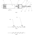
- FIG. 1 is a structure schematic diagram of a device for minimally invasive bone harvesting surgery in an embodiment of the invention.
- the device for minimally invasive bone harvesting surgery in this invention includes a cutter 1, a sleeve 2, a material collection device 3, and a drive control system 5.
- FIG. 2 is a structure schematic diagram of a cutter in the device for minimally invasive bone harvesting surgery in another embodiment of the invention. As shown in FIG. 2 , the cutter includes a head 11 and a spiral conveying portion 12.
- the head 11 has a main effect of guiding the cutter deep into the bone tissue, the head 11 can be a grinding bit or drill bit, etc.
- the head 11 can be a blunt end in small diameter which is not edged and can also be provided with a plurality of cutting edges.
- the head 11 may be a cutting head capable of cutting bone tissues; while in other embodiments, the head 11 may be a blunt head only capable of guiding the cutter into the bone tissue.
- the shape and surface feature of the head 11 can be differently designed according to different demands.
- the shape of the head is usually central symmetric. More particularly, the shape of the head may be a sphere, ellipsoid, umbrella, hemisphere, semi-ellipsoid, hemisphere+cylinder, semi-ellipsoid+cylinder, taper, or cylinder, and the head can be any of the head whose contact surface in contact with bone is a blunt contact surface.
- the proper width of the widest position of the cross section of the blunt end is normally 1.2mm- 15mm.
- the surface of the head 11 can be a smooth surface or a matte surface.
- the head 11 can also be provided with a cutting edge/blade.
- the cutting edge can be a central symmetric spiral cutting edge or a cutting edge with an irregularly disposed surface such as a chisel cutting edge, a longitudinal cutting edge, an oblique cutting edge and so on.
- the cutting edge of the head 11 can be straight, spiral, or inclined. To avoid hurting cortical bone, a shallow or non-sharp cutting edge is preferred when the cutting edge is disposed.
- FIG. 2 is the structure schematic diagram of the cutter in the device for minimally invasive bone harvesting surgery in an embodiment of the invention.
- the spiral conveying portion 12 is provided with a plurality of spiral blades 121, and a plurality of spiral grooves 122 are formed.
- Cancellous bone harvested by the head 11 is conveyed backward along the spiral conveying portion 12.
- the length of the spiral of the spiral conveying portion 12 can be adjusted according to the actual needs.
- the main work of the spiral conveying portion 12 is the transmission of the cut bone tissue. While the head 11 is a blunt end which is not edged, the cutting of the bone tissue is mainly relied on the spiral conveying portion 12, and at least one spiral blade 121 which can cut the bone tissue is disposed at the front end of the spiral conveying portion 12 close to the head.
- the first spiral blade 121 of the spiral conveying portion 12 close to the head is connected with the head 11.
- a certain distance is provided between the first spiral blade 121 of the spiral conveying portion close to the head and the head, and the distance which is set properly can ensure that the harvested bone tissue is smoothly conveyed backward along the spiral grooves 122 of the spiral conveying portion 12.
- the thickness of the spiral blade 121 of the spiral conveying portion 12 is relative small, the width of each spiral grooves 122 is relative large, and the harvested bone tissue is conveyed by the spiral grooves 122.
- the head 11 of the invention rotates and minces the cancellous bone, and the spiral conveying portion 12 conveys the cancellous bone backward.
- the spiral conveying portion 12 rotates, due to the gravity of the materials and the friction force generated between the materials and the groove wall of the spiral groove 122 of the spiral conveying portion 12 and between the materials and the inner wall of the sleeve 2, the materials can only be moved backward along the groove bottom of the spiral groove 122 under the push of the spiral blade 121.
- the conveyance of the materials in the middle section mainly depends on the thrust force of the subsequently advanced materials.
- the conveyance of the materials along the conveying pathway of the spiral conveying portion 12 is a sliding movement.
- the rotating spiral blades 121 push to convey the materials, but the materials do not rotate with the spiral blades 121.
- the key is the gravity of the materials themselves, the friction force of the sleeve 2 against the materials and the reverse pressure generated when the cutter 1 is pushed forward and extrudes the cancellous bone.
- FIG. 1 is the schematic diagram, where the external screw thread is drawn only for illustration. In fact, the length of the spiral conveying portion 12 only needs to satisfy the smooth conveyance of the materials. In a preferred embodiment, in order to better complete the conveyance of the materials, the external screw thread of the spiral conveying portion 12 is extended at least to the position of the material collection device 3.
- Both of the above mentioned materials and the materials that may be mentioned hereinbelow refer to the cancellous bone harvested by the cutter of the device for minimally invasive bone harvesting surgery.
- the pitch of the spiral conveying portion can be 1mm- 30mm, and the spiral angle thereof may be 10°-89°.
- the sleeve 2 is sleeved on the cutter 1, and the head 11 and at least a part of the external screw thread on the surface of the spiral conveying portion 12 are exposed out from the sleeve 2 during work.
- at least a half circle of the screw thread of the spiral conveying portion 12 is exposed out from the sleeve 2, and this is mainly for the cutting of the spiral blades 121 of the spiral conveying portion 12 if the head 11 has no cutting edge.
- the exposed screw threads or the spiral blades should not be too many, since the smooth backward conveyance of the harvested bone tissue also needs to be ensured.
- the sleeve 2 is divided into two parts, which are the first part 21 and the second part 22, wherein the first part 21 is close to the head 11, and the second part 22 is away from the head 11.
- the diameter of the cross section of the second part 22 is larger than that of the first part 21.
- a depth limiting safety step 221 is disposed at the junction of the second part 22 and the first part 21 of the sleeve 2.
- the depth limiting safety step 221 can limit the depth of the cutter 1 entering the bone, thereby preventing the cutter 1 from penetrating the cortical bone.
- another protection mechanism or structure capable of effectively limiting the depth of the cutter 1 entering the bone may also be disposed at the junction of the second part 22 and the first part 21 of the sleeve 2.
- the interior of the sleeve 2 is a hollow structure.
- the diameter of the cross section of the sleeve 2 gradually increases from the position of the head 11 along a direction D away from the head 11, and the increasing of the diameter of the cross section of the sleeve 2 from the front end to the back end (take the position of the head 11 as the front end) can ensure there is a large space for collecting the materials and can reduce the resistance of the conveyance of the materials, thereby conveying the materials more timely and effectively.
- an edge 23 of a front end surface of the sleeve 2 can be rounded or chamfered. In other words, rounding or chamfering can be applied to the edge 23 of the front end surface of the sleeve 2. If the edge 23 is chamfered, the edge 23 can be chamfered inward or outward. In this way, the contact area between the device for minimally invasive bone harvesting surgery and the bone tissue can be reduced, thus to reduce the resistance incurred when the device is pushed forward. In other embodiments, a thickness of the side wall of the sleeve 2 can gradually increase backward, which can also reduce the resistance.
- the material collection device 3 is connected with the sleeve 2, wherein a cavity is disposed.
- the cavity is communicated with the hollow body of the sleeve 2.
- the material conveyed by the spiral conveying portion 12 enters into the material collection device 3 for temporary storage, till the material collection device 3 is taken down to allow the bone tissue to be taken out after the bone tissue in a set value is harvested at one time.
- the drive control system 5 drives and controls the cutter 1 to work, and the drive control system 5 mainly includes a motor and a control system.
- the invention also provides a coupling 4, which is used to connect the output shaft of the motor and the rotation shaft of the cutter 1, which make them rotate together to transmit the torque.
- the device for minimally invasive bone harvesting surgery further has a pressure limiting safety device 6.
- the pressure limiting safety device 6 is a spring, and when the pressure of the front end of the head exceeds or falls down a set range, the spring is compressed or released to control the motor to stop rotating.
- the pressure limiting safety device 6 can be located at the position as shown in the figures or can be located between the cutter and the motor or inside the cutter.
- the pressure limiting safety device 6 can be a pressure sensor, and when the pressure of the front end of the head 11 exceeds or is less than a set range, the motor is controlled to stop rotating, such that the advancement of the head 11 is prevented.
- the pressure limiting safety device 6 can be a current detection device, and when the current exceeds or is less than a set range, the motor is controlled to stop rotating, such that the advancement of the head 11 is prevented.
- the pressure limiting safety device 6 can prevent the head 11 from further penetrating the cortical bone.
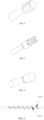
- FIG. 3 is a structure schematic diagram of the cutter in the device for minimally invasive bone harvesting surgery in Embodiment 1 of the invention.
- the head in the embodiment is not edged, and the diameter of the head is small.
- the diameter of the head is the same as or slightly smaller than that of the body of the spiral conveying portion.
- the rotation direction of the spiral blades of the spiral conveying portion is opposite to that shown in FIG. 2 . Since the head is not edged in this embodiment, the first spiral blade of the spiral conveying portion is utilized to realize the cutting of the bone tissue.
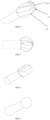
- FIG. 4 is a structure schematic diagram of the head of the cutter in Embodiment 2 of the invention.
- the head 11 has a plurality of spiral cutting edges 111, and none of the spiral cutting edges 111 reach the center 1111 of the end of the head 11.
- the center 1111 of the end of the head 11 is blunt, which is not edged. This is very important in this embodiment.
- the cutting edge of the head does not reach the center 1111 of the end of the head 11, which can ensure that the end of the head 11 has a blunt surface of a certain scale, such that the cutter is prevented from penetrating the cortical bone during the operation.
- the front ends of the spiral cutting edges 111 of the head 11 are all acute angles. Aiming at the characteristics of autologous bone graft surgery, the head 11 of the invention is in a small diameter.
- the front ends of the cutting edges 111 are all acute angles, which can ensure that the end of the head 11 has a certain ability of piercing. However, since the hardness of the cortical bone is much greater than that of the cancellous bone, the cutter can pierce through the cancellous bone during the operation and avoid piercing through the cortical bone at the same time.
- FIG. 5 is a structure schematic diagram of the head of the cutter of the device for minimally invasive bone harvesting surgery in Embodiment 3 of the invention.
- the head in this embodiment is spherical, and a plurality of spiral cutting edges are disposed on the head.
- the spiral cutting edges are oblique, and none of the spiral cutting edges reaches the center of the end surface of the head.
- FIG. 6 is a structure schematic diagram of the head of the cutter of the device for minimally invasive bone harvesting surgery in Embodiment 4 of the invention.
- the head in this embodiment is approximately ellipsoidal, a single cutting edge is disposed at the head, and the cutting edge is disposed longitudinally.
- the front end and other surfaces of the head in contact with the bone tissues are all blunt surfaces.
- FIG. 7 is a structure schematic diagram of the head of the cutter of the device for minimally invasive bone harvesting surgery in Embodiment 5 of the invention.
- the head in this embodiment is spherical without cutting edges, and the surface can be a rough matte surface or a smooth surface.
- the diameter of the head is relatively slightly smaller than that of the edged head in the same type.
- FIG. 8 is a structure schematic diagram of the head of the cutter of the device for minimally invasive bone harvesting surgery in Embodiment 6 of the invention.
- the head in this embodiment is approximately cylindrical, multiple cutting edges are disposed on the head, and the cutting edges are straight. None of the cutting edges reaches the center of the end surface of the head.
- FIG. 9 is a structure schematic diagram of the head of the device for minimally invasive bone harvesting surgery in Embodiment 7 of the invention.
- the shape of the head in the embodiment is a cylinder, multiple cutting edges are disposed on the head, and the cutting edges are non-sharp edges.
- FIG. 10 is a structure schematic diagram of the head of the cutter of the device for minimally invasive bone harvesting surgery in Embodiment 8 of the invention.
- the shape of the head in the embodiment is a cylinder which is not edged.
- the surface can be a rough matte surface or a smooth surface.
- FIG. 11 is a structure schematic diagram of the cutter of the device for minimally invasive bone harvesting surgery in Embodiment 9.
- a major diameter of the first spiral blade 1211 of the spiral conveying portion close to the head is less than that of other spiral blades 1212.
- the screw thread of the front end of the spiral conveying portion has a certain taper. Therefore, it can be ensured that during the cutting process of the bone harvesting device, the screw thread of the front end in contact with the cortical bone is relatively small, which makes the bone harvesting device able to protect the cortical bone from being damaged by cutting during the bone harvesting process.
- the cortical bone can be protected through other methods, and the screw thread of the spiral conveying portion may not have the taper.
- the major diameter of the first spiral blade 1211 can be the same as that of other spiral blades 1212.
Landscapes
- Health & Medical Sciences (AREA)
- Surgery (AREA)
- Life Sciences & Earth Sciences (AREA)
- Biomedical Technology (AREA)
- Medical Informatics (AREA)
- Veterinary Medicine (AREA)
- Public Health (AREA)
- Engineering & Computer Science (AREA)
- General Health & Medical Sciences (AREA)
- Heart & Thoracic Surgery (AREA)
- Nuclear Medicine, Radiotherapy & Molecular Imaging (AREA)
- Molecular Biology (AREA)
- Animal Behavior & Ethology (AREA)
- Dentistry (AREA)
- Oral & Maxillofacial Surgery (AREA)
- Orthopedic Medicine & Surgery (AREA)
- Transplantation (AREA)
- Surgical Instruments (AREA)
Claims (11)
- Vorrichtung für eine minimal-invasive Knochenentnahmeoperation, umfassend eine Schneidevorrichtung (1), eine Hülle (2) und ein Antriebssteuersystem (5) zum Antreiben und Steuern der Schneidevorrichtung (1) zum Betrieb dieser, wobei die Schneidevorrichtung (1) einen Kopf (11) und einen Spiralenförderabschnitt (12) umfasst, wobei ein externes Schraubgewinde auf einer Fläche des Spiralenförderabschnitts (12) angeordnet ist, die Hülle (2) auf die Schneidevorrichtung (1) gehüllt ist, der Kopf (11) und mindestens ein Teil des externen Schraubgewindes der Fläche des Spiralenförderabschnitts (12) von der Hülle (2) freigelegt sind, ein Spiralenwinkel des Spiralenförderabschnitts (12) von 10° bis 89° reicht und das externe Schraubgewinde des Spiralenförderabschnitts (12) mit einer Vielzahl von Spiralklingen (121) versehen ist,
dadurch gekennzeichnet, dass ein Hauptdurchmesser einer ersten Spiralklinge (1211) des Spiralenförderabschnitts (12), die nah zu dem Kopf (11) ist, kleiner als der von anderen Spiralklingen (121) ist. - Vorrichtung für eine minimal-invasive Knochenentnahmeoperation nach Anspruch 1, wobei eine Knochenkontaktfläche des Kopfes (11) zum Kontakt mit Knochengewebe eine stumpfe Kontaktfläche ist.
- Vorrichtung für eine minimal-invasive Knochenentnahmeoperation nach Anspruch 1, wobei der Kopf (11) ein stumpfes Ende aufweist, das nicht geschärft ist.
- Vorrichtung für eine minimal-invasive Knochenentnahmeoperation nach Anspruch 1, wobei der Kopf (11) mit einer Schneidkante (111) versehen ist und eine Mitte (1111) eines Endes des Kopfes (11) eine stumpfe Fläche ist.
- Vorrichtung für eine minimal-invasive Knochenentnahmeoperation nach Anspruch 1, wobei der Kopf (11) mit einer Schneidkante (111) versehen ist und die Schneidkante (111) eine flache Schneidkante oder eine nicht scharfe Schneidkante ist.
- Vorrichtung für eine minimal-invasive Knochenentnahmeoperation nach Anspruch 1, wobei die Hülle (2) hohl ist, die Hülle (2) in einen ersten Teil (21) und einen zweiten Teil (22) unterteilt ist, der erste Teil (21) nahe dem Kopf (11) ist und der zweite Teil (22) von dem Kopf (11) weg ist; ein Durchmesser eines Querschnitts des zweiten Teils (22) größer als ein Querschnitt des ersten Teils (21) ist und eine Tiefenbegrenzungssicherheitsstufe (221) an einer Verbindungsstelle des zweiten Teils (22) und des ersten Teils (21) der Hülle (2) angeordnet ist.
- Vorrichtung für eine minimal-invasive Knochenentnahmeoperation nach Anspruch 6, wobei ein Durchmesser eines Querschnitts der Hülle (2) von der Position des Kopfes (11) entlang einer Richtung von dem Kopf (11) weg allmählich zunimmt.
- Vorrichtung für eine minimal-invasive Knochenentnahmeoperation nach Anspruch 6, wobei eine Kante (23) einer vorderen Endfläche der Hülle (2) gerundet oder abgeschrägt ist.
- Vorrichtung für eine minimal-invasive Knochenentnahmeoperation nach Anspruch 1, weiterhin umfassend eine Druckbegrenzungssicherheitsvorrichtung (6), wobei die Druckbegrenzungssicherheitsvorrichtung (6) eine Feder ist und, wenn der Druck eines vorderen Endes des Kopfes (11) einen Sollbereich übersteigt oder unter diesen fällt, die Feder zum Steuern eines Motors dahingehend, seine Drehung zu stoppen, zusammengedrückt oder freigegeben wird.
- Vorrichtung für eine minimal-invasive Knochenentnahmeoperation nach Anspruch 1, weiterhin umfassend eine Druckbegrenzungssicherheitsvorrichtung (6), wobei die Druckbegrenzungssicherheitsvorrichtung (6) eine Stromerfassungsvorrichtung ist zum Steuern eines Motors dahingehend, seine Drehung zu stoppen, durch Erfassen eines Stroms des Motors, wenn der Strom einen Sollbereich übersteigt oder unter diesen fällt, ist.
- Vorrichtung für eine minimal-invasive Knochenentnahmeoperation nach Anspruch 1, weiterhin umfassend eine Druckbegrenzungssicherheitsvorrichtung (6), wobei die Druckbegrenzungssicherheitsvorrichtung (6) ein Drucksensor ist und, wenn ein Druck eines vorderen Endes des Kopfes (11) einen Sollbereich übersteigt oder unter diesen fällt, ein Motor dahingehend gesteuert wird, seine Drehung zu stoppen.
Applications Claiming Priority (1)
| Application Number | Priority Date | Filing Date | Title |
|---|---|---|---|
| CN201710170645.3A CN108618825B (zh) | 2017-03-21 | 2017-03-21 | 微创骨组织手术设备 |
Publications (3)
| Publication Number | Publication Date |
|---|---|
| EP3378417A1 EP3378417A1 (de) | 2018-09-26 |
| EP3378417B1 true EP3378417B1 (de) | 2024-02-14 |
| EP3378417C0 EP3378417C0 (de) | 2024-02-14 |
Family
ID=59387937
Family Applications (1)
| Application Number | Title | Priority Date | Filing Date |
|---|---|---|---|
| EP17182534.2A Active EP3378417B1 (de) | 2017-03-21 | 2017-07-21 | Vorrichtung für minimalinvasive chirurgie zur knochenentnahme |
Country Status (3)
| Country | Link |
|---|---|
| US (1) | US10456147B2 (de) |
| EP (1) | EP3378417B1 (de) |
| CN (1) | CN108618825B (de) |
Families Citing this family (8)
| Publication number | Priority date | Publication date | Assignee | Title |
|---|---|---|---|---|
| CN108618824A (zh) * | 2017-03-21 | 2018-10-09 | 浙江复润医疗科技有限公司 | 微创骨组织手术设备的刀具 |
| CN109480921A (zh) * | 2018-10-25 | 2019-03-19 | 宝鸡市中医医院 | 一种脊柱微创手术器械限深装置 |
| CN109528244A (zh) * | 2018-12-28 | 2019-03-29 | 河南农业大学 | 活体采样器及适用于该活体采样器的钻头 |
| CN109528245A (zh) * | 2018-12-28 | 2019-03-29 | 河南农业大学 | 一种取样头可更换的活体采样器 |
| US11471168B2 (en) * | 2019-12-20 | 2022-10-18 | Innovations 4 Surgery, LLC | Medical devices and related methods for transforming bone, other tissue, or material |
| CN112842453B (zh) * | 2021-02-06 | 2022-06-21 | 南京汉尔斯生物科技有限公司 | 一种轴向微创取骨装置 |
| CN113974763B (zh) * | 2021-12-07 | 2023-07-21 | 河南省中医药研究院 | 一种微创手术用智能磨钻机械臂 |
| CN117084749B (zh) * | 2023-10-13 | 2024-01-02 | 四川大学华西医院 | 一种安全快速的取骨器 |
Citations (4)
| Publication number | Priority date | Publication date | Assignee | Title |
|---|---|---|---|---|
| US20050203527A1 (en) * | 2004-03-03 | 2005-09-15 | Scimed Life Systems, Inc. | Apparatus and methods for removing vertebral bone and disc tissue |
| US20110112563A1 (en) * | 2006-06-30 | 2011-05-12 | Atheromed, Inc. | Atherectomy devices and methods |
| US20120209273A1 (en) * | 2010-11-15 | 2012-08-16 | Zaretzka Gary D | Tissue removal system with retention mechanism |
| US20140180321A1 (en) * | 2012-12-20 | 2014-06-26 | Spine View, Inc. | Discectomy devices and methods |
Family Cites Families (19)
| Publication number | Priority date | Publication date | Assignee | Title |
|---|---|---|---|---|
| US2526662A (en) * | 1946-12-10 | 1950-10-24 | Herbert E Hipps | Bone meal extractor |
| US6071284A (en) * | 1995-10-30 | 2000-06-06 | Biomedical Enterprises, Inc. | Materials collection system and uses thereof |
| US20070270771A1 (en) | 2006-04-24 | 2007-11-22 | Ralph James D | Autologous bone harvest during osteotomy and bone drilling procedures |
| CN101332112A (zh) * | 2007-04-28 | 2008-12-31 | 侯慧芳 | 微创取骨设备 |
| BR112013025667B1 (pt) * | 2011-04-07 | 2021-01-12 | Synthes Gmbh | broca cirúrgica e método para carregar uma broca de corte em uma broca cirúrgica |
| US8801713B2 (en) * | 2011-04-07 | 2014-08-12 | DePuy Synthes Products, LLC | Surgical drill instrument with motor and locking mechanism to receive an attachment and a cutting burr |
| CN102247174B (zh) * | 2011-08-18 | 2013-06-12 | 南京大学医学院附属鼓楼医院 | 组合式骨肿瘤微创切开活检器 |
| CN202409040U (zh) * | 2011-12-31 | 2012-09-05 | 北京惠慈假肢医疗用品开发有限责任公司 | 骨钻 |
| KR101159560B1 (ko) * | 2012-04-02 | 2012-06-25 | (주)애크로덴트 | 본펜, 본핀, 본펜 세트, 본핀 세트 및 이들과 이니셜 드릴을 포함하는 본펜 키트 |
| US9572589B2 (en) * | 2012-07-10 | 2017-02-21 | Stryker European Holdings I, Llc | Drill guide |
| BR112015021082B1 (pt) * | 2013-03-01 | 2022-05-10 | Ethicon Endo-Surgery, Inc | Instrumento cirúrgico |
| US9603610B2 (en) | 2013-03-15 | 2017-03-28 | DePuy Synthes Products, Inc. | Tools and methods for tissue removal |
| KR101295863B1 (ko) * | 2013-06-28 | 2013-08-12 | 황적희 | 신속한 교체가 가능한 본 컬렉터 |
| US20150025534A1 (en) * | 2013-07-17 | 2015-01-22 | Bone Buddies, Llc | Apparatus and method for bone harvesting |
| CN203539409U (zh) * | 2013-10-30 | 2014-04-16 | 重庆西山科技有限公司 | 加长型磨削刀具 |
| ES2854173T3 (es) * | 2014-03-11 | 2021-09-20 | Stryker European Holdings I Llc | Extractor de tejido para autoinjertos intramedulares |
| CN203935242U (zh) * | 2014-06-16 | 2014-11-12 | 李万里 | 微创快速取骨器 |
| CN204542282U (zh) * | 2014-12-31 | 2015-08-12 | 李万里 | 微创快速取骨器 |
| CN207575191U (zh) * | 2017-03-21 | 2018-07-06 | 浙江复润医疗科技有限公司 | 微创骨组织手术设备 |
-
2017
- 2017-03-21 CN CN201710170645.3A patent/CN108618825B/zh active Active
- 2017-07-21 US US15/656,855 patent/US10456147B2/en active Active
- 2017-07-21 EP EP17182534.2A patent/EP3378417B1/de active Active
Patent Citations (4)
| Publication number | Priority date | Publication date | Assignee | Title |
|---|---|---|---|---|
| US20050203527A1 (en) * | 2004-03-03 | 2005-09-15 | Scimed Life Systems, Inc. | Apparatus and methods for removing vertebral bone and disc tissue |
| US20110112563A1 (en) * | 2006-06-30 | 2011-05-12 | Atheromed, Inc. | Atherectomy devices and methods |
| US20120209273A1 (en) * | 2010-11-15 | 2012-08-16 | Zaretzka Gary D | Tissue removal system with retention mechanism |
| US20140180321A1 (en) * | 2012-12-20 | 2014-06-26 | Spine View, Inc. | Discectomy devices and methods |
Also Published As
| Publication number | Publication date |
|---|---|
| US20180271543A1 (en) | 2018-09-27 |
| US10456147B2 (en) | 2019-10-29 |
| CN108618825A (zh) | 2018-10-09 |
| EP3378417A1 (de) | 2018-09-26 |
| CN108618825B (zh) | 2024-06-18 |
| EP3378417C0 (de) | 2024-02-14 |
Similar Documents
| Publication | Publication Date | Title |
|---|---|---|
| EP3378417B1 (de) | Vorrichtung für minimalinvasive chirurgie zur knochenentnahme | |
| CN108742768A (zh) | 微创取骨设备 | |
| US20230270480A1 (en) | Implantable compression screws | |
| US6022354A (en) | Bone harvesting collection and delivery system | |
| US20190262007A1 (en) | Drill bit and method for producing a drill bit | |
| US7641677B2 (en) | Compression bone fragment wire | |
| US8523866B2 (en) | Modular tapered hollow reamer for medical applications | |
| AU758769B2 (en) | Device with a flexible shaft for removing bone grafts | |
| US20120179161A1 (en) | Surgical instruments for cutting cavities in intramedullary canals | |
| JP6864945B2 (ja) | 低侵襲骨組織手術器具 | |
| US11278335B2 (en) | Implantable compression screws | |
| AU2017268657B2 (en) | Methods and devices for cutting and removing tissue from a body | |
| US8403931B2 (en) | Modular tapered hollow reamer for medical applications | |
| CN207575191U (zh) | 微创骨组织手术设备 | |
| CN105395236A (zh) | 微创取骨器 | |
| EP3222226A1 (de) | Reamer des intramedullären kanals | |
| CN210009092U (zh) | 微创取骨设备 | |
| CN108618824A (zh) | 微创骨组织手术设备的刀具 | |
| EP3463105B1 (de) | Knochenschraube mit differentieller kompression | |
| CN205322417U (zh) | 微创取骨器 | |
| CN207575190U (zh) | 微创骨组织手术设备的刀具 | |
| AU2018420063B2 (en) | Frustoconical hair punch | |
| US12023047B1 (en) | Cannulated trephine | |
| CN115644981A (zh) | 一种微创手术刀具 | |
| CN119606483A (zh) | 一种微创取骨设备 |
Legal Events
| Date | Code | Title | Description |
|---|---|---|---|
| STAA | Information on the status of an ep patent application or granted ep patent |
Free format text: STATUS: EXAMINATION IS IN PROGRESS |
|
| PUAI | Public reference made under article 153(3) epc to a published international application that has entered the european phase |
Free format text: ORIGINAL CODE: 0009012 |
|
| 17P | Request for examination filed |
Effective date: 20170721 |
|
| AK | Designated contracting states |
Kind code of ref document: A1 Designated state(s): AL AT BE BG CH CY CZ DE DK EE ES FI FR GB GR HR HU IE IS IT LI LT LU LV MC MK MT NL NO PL PT RO RS SE SI SK SM TR |
|
| AX | Request for extension of the european patent |
Extension state: BA ME |
|
| GRAP | Despatch of communication of intention to grant a patent |
Free format text: ORIGINAL CODE: EPIDOSNIGR1 |
|
| STAA | Information on the status of an ep patent application or granted ep patent |
Free format text: STATUS: GRANT OF PATENT IS INTENDED |
|
| RIC1 | Information provided on ipc code assigned before grant |
Ipc: A61B 90/00 20160101ALN20230907BHEP Ipc: A61B 17/16 20060101AFI20230907BHEP |
|
| RIC1 | Information provided on ipc code assigned before grant |
Ipc: A61B 90/00 20160101ALN20230914BHEP Ipc: A61B 17/16 20060101AFI20230914BHEP |
|
| RIC1 | Information provided on ipc code assigned before grant |
Ipc: A61B 90/00 20160101ALN20230917BHEP Ipc: A61B 17/16 20060101AFI20230917BHEP |
|
| INTG | Intention to grant announced |
Effective date: 20231005 |
|
| GRAS | Grant fee paid |
Free format text: ORIGINAL CODE: EPIDOSNIGR3 |
|
| GRAA | (expected) grant |
Free format text: ORIGINAL CODE: 0009210 |
|
| STAA | Information on the status of an ep patent application or granted ep patent |
Free format text: STATUS: THE PATENT HAS BEEN GRANTED |
|
| AK | Designated contracting states |
Kind code of ref document: B1 Designated state(s): AL AT BE BG CH CY CZ DE DK EE ES FI FR GB GR HR HU IE IS IT LI LT LU LV MC MK MT NL NO PL PT RO RS SE SI SK SM TR |
|
| REG | Reference to a national code |
Ref country code: GB Ref legal event code: FG4D |
|
| REG | Reference to a national code |
Ref country code: CH Ref legal event code: EP |
|
| REG | Reference to a national code |
Ref country code: DE Ref legal event code: R096 Ref document number: 602017079098 Country of ref document: DE |
|
| REG | Reference to a national code |
Ref country code: IE Ref legal event code: FG4D |
|
| U01 | Request for unitary effect filed |
Effective date: 20240307 |
|
| U07 | Unitary effect registered |
Designated state(s): AT BE BG DE DK EE FI FR IT LT LU LV MT NL PT SE SI Effective date: 20240315 |
|
| PG25 | Lapsed in a contracting state [announced via postgrant information from national office to epo] |
Ref country code: IS Free format text: LAPSE BECAUSE OF FAILURE TO SUBMIT A TRANSLATION OF THE DESCRIPTION OR TO PAY THE FEE WITHIN THE PRESCRIBED TIME-LIMIT Effective date: 20240614 |
|
| PG25 | Lapsed in a contracting state [announced via postgrant information from national office to epo] |
Ref country code: GR Free format text: LAPSE BECAUSE OF FAILURE TO SUBMIT A TRANSLATION OF THE DESCRIPTION OR TO PAY THE FEE WITHIN THE PRESCRIBED TIME-LIMIT Effective date: 20240515 |
|
| PG25 | Lapsed in a contracting state [announced via postgrant information from national office to epo] |
Ref country code: RS Free format text: LAPSE BECAUSE OF FAILURE TO SUBMIT A TRANSLATION OF THE DESCRIPTION OR TO PAY THE FEE WITHIN THE PRESCRIBED TIME-LIMIT Effective date: 20240514 Ref country code: HR Free format text: LAPSE BECAUSE OF FAILURE TO SUBMIT A TRANSLATION OF THE DESCRIPTION OR TO PAY THE FEE WITHIN THE PRESCRIBED TIME-LIMIT Effective date: 20240214 |
|
| PG25 | Lapsed in a contracting state [announced via postgrant information from national office to epo] |
Ref country code: ES Free format text: LAPSE BECAUSE OF FAILURE TO SUBMIT A TRANSLATION OF THE DESCRIPTION OR TO PAY THE FEE WITHIN THE PRESCRIBED TIME-LIMIT Effective date: 20240214 |
|
| PG25 | Lapsed in a contracting state [announced via postgrant information from national office to epo] |
Ref country code: RS Free format text: LAPSE BECAUSE OF FAILURE TO SUBMIT A TRANSLATION OF THE DESCRIPTION OR TO PAY THE FEE WITHIN THE PRESCRIBED TIME-LIMIT Effective date: 20240514 Ref country code: NO Free format text: LAPSE BECAUSE OF FAILURE TO SUBMIT A TRANSLATION OF THE DESCRIPTION OR TO PAY THE FEE WITHIN THE PRESCRIBED TIME-LIMIT Effective date: 20240514 Ref country code: IS Free format text: LAPSE BECAUSE OF FAILURE TO SUBMIT A TRANSLATION OF THE DESCRIPTION OR TO PAY THE FEE WITHIN THE PRESCRIBED TIME-LIMIT Effective date: 20240614 Ref country code: HR Free format text: LAPSE BECAUSE OF FAILURE TO SUBMIT A TRANSLATION OF THE DESCRIPTION OR TO PAY THE FEE WITHIN THE PRESCRIBED TIME-LIMIT Effective date: 20240214 Ref country code: GR Free format text: LAPSE BECAUSE OF FAILURE TO SUBMIT A TRANSLATION OF THE DESCRIPTION OR TO PAY THE FEE WITHIN THE PRESCRIBED TIME-LIMIT Effective date: 20240515 Ref country code: ES Free format text: LAPSE BECAUSE OF FAILURE TO SUBMIT A TRANSLATION OF THE DESCRIPTION OR TO PAY THE FEE WITHIN THE PRESCRIBED TIME-LIMIT Effective date: 20240214 |
|
| PG25 | Lapsed in a contracting state [announced via postgrant information from national office to epo] |
Ref country code: PL Free format text: LAPSE BECAUSE OF FAILURE TO SUBMIT A TRANSLATION OF THE DESCRIPTION OR TO PAY THE FEE WITHIN THE PRESCRIBED TIME-LIMIT Effective date: 20240214 |
|
| U20 | Renewal fee for the european patent with unitary effect paid |
Year of fee payment: 8 Effective date: 20240717 |
|
| PG25 | Lapsed in a contracting state [announced via postgrant information from national office to epo] |
Ref country code: PL Free format text: LAPSE BECAUSE OF FAILURE TO SUBMIT A TRANSLATION OF THE DESCRIPTION OR TO PAY THE FEE WITHIN THE PRESCRIBED TIME-LIMIT Effective date: 20240214 |
|
| PG25 | Lapsed in a contracting state [announced via postgrant information from national office to epo] |
Ref country code: SM Free format text: LAPSE BECAUSE OF FAILURE TO SUBMIT A TRANSLATION OF THE DESCRIPTION OR TO PAY THE FEE WITHIN THE PRESCRIBED TIME-LIMIT Effective date: 20240214 |
|
| PG25 | Lapsed in a contracting state [announced via postgrant information from national office to epo] |
Ref country code: CZ Free format text: LAPSE BECAUSE OF FAILURE TO SUBMIT A TRANSLATION OF THE DESCRIPTION OR TO PAY THE FEE WITHIN THE PRESCRIBED TIME-LIMIT Effective date: 20240214 |
|
| PG25 | Lapsed in a contracting state [announced via postgrant information from national office to epo] |
Ref country code: SK Free format text: LAPSE BECAUSE OF FAILURE TO SUBMIT A TRANSLATION OF THE DESCRIPTION OR TO PAY THE FEE WITHIN THE PRESCRIBED TIME-LIMIT Effective date: 20240214 |
|
| PG25 | Lapsed in a contracting state [announced via postgrant information from national office to epo] |
Ref country code: SM Free format text: LAPSE BECAUSE OF FAILURE TO SUBMIT A TRANSLATION OF THE DESCRIPTION OR TO PAY THE FEE WITHIN THE PRESCRIBED TIME-LIMIT Effective date: 20240214 Ref country code: SK Free format text: LAPSE BECAUSE OF FAILURE TO SUBMIT A TRANSLATION OF THE DESCRIPTION OR TO PAY THE FEE WITHIN THE PRESCRIBED TIME-LIMIT Effective date: 20240214 Ref country code: RO Free format text: LAPSE BECAUSE OF FAILURE TO SUBMIT A TRANSLATION OF THE DESCRIPTION OR TO PAY THE FEE WITHIN THE PRESCRIBED TIME-LIMIT Effective date: 20240214 Ref country code: CZ Free format text: LAPSE BECAUSE OF FAILURE TO SUBMIT A TRANSLATION OF THE DESCRIPTION OR TO PAY THE FEE WITHIN THE PRESCRIBED TIME-LIMIT Effective date: 20240214 |
|
| REG | Reference to a national code |
Ref country code: DE Ref legal event code: R097 Ref document number: 602017079098 Country of ref document: DE |
|
| PLBE | No opposition filed within time limit |
Free format text: ORIGINAL CODE: 0009261 |
|
| STAA | Information on the status of an ep patent application or granted ep patent |
Free format text: STATUS: NO OPPOSITION FILED WITHIN TIME LIMIT |
|
| 26N | No opposition filed |
Effective date: 20241115 |
|
| PG25 | Lapsed in a contracting state [announced via postgrant information from national office to epo] |
Ref country code: MC Free format text: LAPSE BECAUSE OF FAILURE TO SUBMIT A TRANSLATION OF THE DESCRIPTION OR TO PAY THE FEE WITHIN THE PRESCRIBED TIME-LIMIT Effective date: 20240214 |
|
| REG | Reference to a national code |
Ref country code: CH Ref legal event code: PL |
|
| GBPC | Gb: european patent ceased through non-payment of renewal fee |
Effective date: 20240721 |
|
| PG25 | Lapsed in a contracting state [announced via postgrant information from national office to epo] |
Ref country code: CH Free format text: LAPSE BECAUSE OF NON-PAYMENT OF DUE FEES Effective date: 20240731 |
|
| PG25 | Lapsed in a contracting state [announced via postgrant information from national office to epo] |
Ref country code: GB Free format text: LAPSE BECAUSE OF NON-PAYMENT OF DUE FEES Effective date: 20240721 |
|
| PG25 | Lapsed in a contracting state [announced via postgrant information from national office to epo] |
Ref country code: IE Free format text: LAPSE BECAUSE OF NON-PAYMENT OF DUE FEES Effective date: 20240721 |
|
| U20 | Renewal fee for the european patent with unitary effect paid |
Year of fee payment: 9 Effective date: 20250729 |
|
| PG25 | Lapsed in a contracting state [announced via postgrant information from national office to epo] |
Ref country code: CY Free format text: LAPSE BECAUSE OF FAILURE TO SUBMIT A TRANSLATION OF THE DESCRIPTION OR TO PAY THE FEE WITHIN THE PRESCRIBED TIME-LIMIT; INVALID AB INITIO Effective date: 20170721 |
|
| PG25 | Lapsed in a contracting state [announced via postgrant information from national office to epo] |
Ref country code: HU Free format text: LAPSE BECAUSE OF FAILURE TO SUBMIT A TRANSLATION OF THE DESCRIPTION OR TO PAY THE FEE WITHIN THE PRESCRIBED TIME-LIMIT; INVALID AB INITIO Effective date: 20170721 |