EP3378370A1 - Dishwasher with rotary-translating spraying arm - Google Patents
Dishwasher with rotary-translating spraying arm Download PDFInfo
- Publication number
- EP3378370A1 EP3378370A1 EP18162180.6A EP18162180A EP3378370A1 EP 3378370 A1 EP3378370 A1 EP 3378370A1 EP 18162180 A EP18162180 A EP 18162180A EP 3378370 A1 EP3378370 A1 EP 3378370A1
- Authority
- EP
- European Patent Office
- Prior art keywords
- hub portion
- dishwasher
- rotation axis
- spraying
- end segment
- Prior art date
- Legal status (The legal status is an assumption and is not a legal conclusion. Google has not performed a legal analysis and makes no representation as to the accuracy of the status listed.)
- Granted
Links
Images


Classifications
-
- A—HUMAN NECESSITIES
- A47—FURNITURE; DOMESTIC ARTICLES OR APPLIANCES; COFFEE MILLS; SPICE MILLS; SUCTION CLEANERS IN GENERAL
- A47L—DOMESTIC WASHING OR CLEANING; SUCTION CLEANERS IN GENERAL
- A47L15/00—Washing or rinsing machines for crockery or tableware
- A47L15/42—Details
- A47L15/4278—Nozzles
- A47L15/428—Rotary nozzles
-
- A—HUMAN NECESSITIES
- A47—FURNITURE; DOMESTIC ARTICLES OR APPLIANCES; COFFEE MILLS; SPICE MILLS; SUCTION CLEANERS IN GENERAL
- A47L—DOMESTIC WASHING OR CLEANING; SUCTION CLEANERS IN GENERAL
- A47L15/00—Washing or rinsing machines for crockery or tableware
- A47L15/14—Washing or rinsing machines for crockery or tableware with stationary crockery baskets and spraying devices within the cleaning chamber
- A47L15/18—Washing or rinsing machines for crockery or tableware with stationary crockery baskets and spraying devices within the cleaning chamber with movably-mounted spraying devices
- A47L15/22—Rotary spraying devices
- A47L15/23—Rotary spraying devices moved by means of the sprays
-
- A—HUMAN NECESSITIES
- A47—FURNITURE; DOMESTIC ARTICLES OR APPLIANCES; COFFEE MILLS; SPICE MILLS; SUCTION CLEANERS IN GENERAL
- A47L—DOMESTIC WASHING OR CLEANING; SUCTION CLEANERS IN GENERAL
- A47L15/00—Washing or rinsing machines for crockery or tableware
-
- A—HUMAN NECESSITIES
- A47—FURNITURE; DOMESTIC ARTICLES OR APPLIANCES; COFFEE MILLS; SPICE MILLS; SUCTION CLEANERS IN GENERAL
- A47L—DOMESTIC WASHING OR CLEANING; SUCTION CLEANERS IN GENERAL
- A47L15/00—Washing or rinsing machines for crockery or tableware
- A47L15/14—Washing or rinsing machines for crockery or tableware with stationary crockery baskets and spraying devices within the cleaning chamber
- A47L15/18—Washing or rinsing machines for crockery or tableware with stationary crockery baskets and spraying devices within the cleaning chamber with movably-mounted spraying devices
- A47L15/22—Rotary spraying devices
-
- A—HUMAN NECESSITIES
- A47—FURNITURE; DOMESTIC ARTICLES OR APPLIANCES; COFFEE MILLS; SPICE MILLS; SUCTION CLEANERS IN GENERAL
- A47L—DOMESTIC WASHING OR CLEANING; SUCTION CLEANERS IN GENERAL
- A47L15/00—Washing or rinsing machines for crockery or tableware
- A47L15/42—Details
- A47L15/4285—Water-heater arrangements
-
- A—HUMAN NECESSITIES
- A47—FURNITURE; DOMESTIC ARTICLES OR APPLIANCES; COFFEE MILLS; SPICE MILLS; SUCTION CLEANERS IN GENERAL
- A47L—DOMESTIC WASHING OR CLEANING; SUCTION CLEANERS IN GENERAL
- A47L15/00—Washing or rinsing machines for crockery or tableware
- A47L15/42—Details
- A47L15/46—Devices for the automatic control of the different phases of cleaning ; Controlling devices
-
- A—HUMAN NECESSITIES
- A47—FURNITURE; DOMESTIC ARTICLES OR APPLIANCES; COFFEE MILLS; SPICE MILLS; SUCTION CLEANERS IN GENERAL
- A47L—DOMESTIC WASHING OR CLEANING; SUCTION CLEANERS IN GENERAL
- A47L15/00—Washing or rinsing machines for crockery or tableware
- A47L15/42—Details
- A47L15/4278—Nozzles
- A47L15/4282—Arrangements to change or modify spray pattern or direction
Definitions
- the present invention relates to a dishwasher of the type comprising a washing container for receiving dishes to be washed, a spraying device for spraying a washing liquid on the dishes arranged in the washing container and a heating device adapted to heat the washing liquid.
- Dishwashers are known in which the washing liquid is distributed in the washing container and on the dishes by means of nozzles formed in rotating arms hydraulically connected with a pump for the pressurization and recirculation of the washing liquid.
- the rotating arms are put in rotation by virtue of an orientation of the nozzles of the arms, with at least one jet vector component in a direction tangential to the vertical rotation axis, and the consequent reaction force of the washing liquid jet.
- the washing liquid is not uniformly distributed in all areas of the washing container, with a lack of distribution of the liquid in the corner areas of the washing container which are not covered by the movement of the spraying arms.
- stationary spraying devices or nozzles are known, whose invariable spraying directions may not, however, guarantee a uniform washing of all the dishes arranged in the washing container.
- washing liquid distribution bars have been proposed, equipped with spraying nozzles, and moved with an alternating rectilinear movement by virtue of a motorized movement system.
- rotating spraying arms are known, near the ends thereof secondary spraying arms are connected, also rotating, which perform a satellite movement with respect to the main movement of the rotating arms.
- a dishwasher comprises a washing container for receiving dishes to be washed, at least one spraying arm rotatably mounted in the washing container and forming a plurality of spraying nozzles for spraying a washing liquid in the washing container, a pump hydraulically connected with the spraying arm to feed the washing liquid to the spraying nozzles, a heating device for heating the washing liquid, and control means which control the actuation of the pump and of the heating means,
- the spraying arm comprises a hub portion rotatably connected about a rotation axis, and a bar portion extending from the hub portion in a direction transversal (preferably radial) to the rotation axis, towards an internal surface of the washing container, the bar portion forming a plurality of said spraying nozzles and being connected to the hub portion so as to rotate together with the hub portion about the rotation axis, characterized in that:
- the bar portion comprises an end segment translatable with respect to the hub portion away from and towards the rotation axis
- the spraying arm comprises a synchronization device connected with the washing container and with the end segment and configured to synchronize the translation movement of the end segment with the rotary movement of the hub portion so as to translate the end segment depending on the distance of the internal surface from the rotation axis.
- the end segment moves away from the rotation axis at the corner regions of the washing container which are further away from the rotation axis, and the end segment moves towards the rotation axis at the side regions of the washing container which are closer to the rotation axis.
- Figure 8 is a diagrammatic, top view of a cam track of the spraying arm in Figure 7 .
- a dishwasher 1 comprises at least one washing container 2 adapted to receive dishes 3 to be washed and closable by means of a door 4 (indicated in Figure 1 only diagrammatically, by means of a dashed line).
- At least one spraying arm 5 is positioned, rotatably mounted in the washing container and forming a plurality of spraying nozzles 6 for spraying a washing liquid on the dishes 3 received in the washing container 2.
- a pump 7 is hydraulically connected, for example by means of a supply duct 8, with the spraying arm 5 to feed the washing liquid to the spraying nozzles 6.
- the dishwasher 1 further comprises a heating device 9 adapted to heat the washing liquid, for example an electrical resistor arranged in a washing liquid collection tank 10.
- the collection tank 10 preferably formed in a lower region of the washing container 2 or below the washing container 2, is connected with the pump 7 to allow the drawing of the cold or heated washing liquid required for the washing treatment of the dishes 3.
- the collection tank 10 and/or the pump 7 are further connected with an inlet valve 11 for loading mains water, and to a draining duct 12 for draining the washing liquid.
- the dishwasher 1 further comprises control means, for example, an electronic control unit 40, configured to allow the selection of a dish washing treatment program among a plurality of dish washing treatment programs, and to control the actuation of the pump 6, of the heating device 10 and of the inlet valve 11.
- control means for example, an electronic control unit 40, configured to allow the selection of a dish washing treatment program among a plurality of dish washing treatment programs, and to control the actuation of the pump 6, of the heating device 10 and of the inlet valve 11.
- the one or more spraying arms 5 may be put in rotation by virtue of an orientation of the spraying nozzles 6, with at least one jet vector component in a direction tangential to the (vertical) rotation axis 13, and the consequent reaction force of the washing liquid jets produced by means of the pressure and the speed of the liquid conveyed by means of the pump 7.
- the one or more spraying arms 5 may be actuated in rotation by means of a rotary actuator, for example an electric motor or an electromechanic or electrohydraulic actuator.
- the spraying arm 5 comprises a hub portion 14 rotatably supported about a rotation axis 13, and an elongated portion in the shape of a bar 15 extending from the hub portion 14 in a direction transversal (preferably radial) to the rotation axis 13, towards an internal surface 16 of the washing container 2.
- the bar portion 15 forms a plurality of spraying nozzles 6 and is connected to the hub portion 14 so as to rotate together with the hub portion 14 about the rotation axis 13.
- the bar portion 15 comprises an end segment 17 which forms one or more of the spraying nozzles 6 and which is translatable with respect to the hub portion 14 away from and towards the rotation axis 13.
- the spraying arm 5 further comprises a synchronization device 18 connected with the washing container 2 and to the end segment 17 and configured to synchronize the translation movement 20 of the end segment 17 with the rotary movement 21 of the hub portion 14 so as to translate the end segment 17 depending on the distance of the internal surface 16 from the rotation axis 13 ( Figures 4, 5, 6 ).
- the end segment 17 moves away from the rotation axis 13 when the bar portion 15 is oriented towards the corner regions 19 of the washing container 2 which are further away from the rotation axis 13, and the end segment 17 moves towards to the rotation axis 13 when the bar portion 15 is oriented towards the wall regions 22 of the washing container 2 which are closer to the rotation axis 13.
- the rotation axis 13 is substantially vertical and the internal surface 16 is substantially rectangular, as shown in Figures 1 , 4, 5, 6 .
- the bar portion 15 may extend on two opposite sides of the hub portion 14, may protrude in a direction substantially radial with respect to the rotation axis 13, may lie and rotate on a plane substantially perpendicular to the rotation axis 13 and may have a rectilinear development, possibly tapered towards the free ends.
- the hub portion 14 and the bar portion 15 and the end segment 17 may form one or more spraying nozzles 6, so as ensure the most uniform possible washing liquid distribution.
- the spraying arm 5 comprises two translatable end segments 17 (forming the two radially outermost ends of the bar portion 15), arranged on two sides diametrically opposite ( Figures 2 , 4 ) with respect to the hub portion 13 and translatable with respect to one another and with respect to the hub portion 14.
- the synchronization device 18 is configured to make the two end segments 17 translate with respect to the hub portion 14 in an alternate and opposing manner, and in a manner synchronized with the instantaneous orientation of the spraying arm 5 with respect to the washing container 2.
- the spraying arm 5 comprises a single translatable end segment 17 (forming only one of the two radially outermost ends of the bar portion 15), translatable with respect to the hub portion 14 ( Figures 3 , 5 ).
- the synchronization device 18 may be configured to make the single translating end segment 17 translate, with respect to the hub portion 14, in an alternating manner and synchronized with the instantaneous orientation of the spraying arm 5 with respect to the washing container 2.
- the spraying arm 5 comprises two end segments 17 firmly connected to one another and forming both the radially outermost ends of the bar portion 15 or forming the entire bar portion 15.
- the two end segments 17 may be formed in a single piece or connected to one another so as to be translatable as a single body with respect to the hub portion 14 ( Figure 6 ).
- the synchronization device 18 may be configured to make the two end segments 17 together or the entire bar portion 15 translate with respect to the hub portion 14, in an alternating manner and synchronized with the instantaneous orientation of the spraying arm 5 with respect to the washing container 2.
- the synchronization device 18 is configured so as to translate the at least one translatable end segment 17:
- the spraying arm 5 forms one or more spraying nozzles 6, which:
- the end segments 17 are slidably connected, for example, inserted telescopically with the hub portion 14 or with a radially inner portion 23, not translatable, of the bar portion 15.
- a sliding gasket interposed therebetween or a bellow gasket 24 arranged around the sliding/translatable connection may be provided for ( Figures 2, 3 ).
- the hub portion 14, the bar portion 15 and the translatable end segment/s 17 are hollow plastic profiles, preferably made of fiber-filled polymers, e.g., calcium- or talc-filled polypropylene.
- the synchronization device 18 comprises a purely mechanical synchronization transmission with at least one stationary reference member 25 which is stationary with respect to the washing container 2, at least one alternating member 28 connected with the at least one translating end segment 17, and a synchronization mechanism 29 connected with the hub portion 14, to the stationary reference member and to the alternating member 28 to synchronize their relative movements.
- the stationary reference member 25 may comprise, for example, a toothed wheel, a toothed crown, a pulley or a cam ( Figures 2, 3 ), fixed and firmly connected to the washing container 2.
- the stationary reference member 25 is fastened to an extractable dish rack 26 or directly to the washing container 2, preferably together with (and inside) a duct portion 27 to which the hub portion 14 is rotatably coupled.
- the synchronization mechanism 29 may comprise a gear, a lever transmission, a cam or toothed belt transmission, or a crankshaft mechanism.
- the synchronization mechanism 29 comprises:
- Figure 2 shows a spraying arm 5 with a synchronization device 18 which actuates the reciprocating translation of two opposite end segments 17, while Figure 3 shows a spraying arm 5 with a synchronization device 18 which actuates the reciprocating translation of a single end segment 17.
- the hub portion 14 is rotatably connected and in hydraulic communication with a fixed duct portion 27.
- the stationary reference member 25 is a fixed toothed wheel (coaxial to the rotation axis 13), connected to a fixed shaft 34 extending from the inside of the duct portion 27 to the inside of the hub portion 14.
- the de/multiplication mechanism 30 comprises (on one single side or on two opposite sides of the rotation axis 13) a rotatable shaft 36 supported in the hub portion 14 so as to rotate together with the hub portion 14 about the rotation axis 13 and to be capable of rotating, with respect to the hub portion 14, about an own axis 37 spaced apart from the rotation axis 13, as well as a toothed wheel 35 fastened on the rotatable shaft 36 and meshed with the fixed toothed wheel 25.
- the conversion mechanism 31 comprises (on one single side or on two opposite sides of the rotation axis 13) a crank 32 formed by or fastened on the shaft 36 and a rod 33 connected between the crank 32 and the translating end segment 17.
- This embodiment allows a synchronized translation, but not necessarily of identical frequency, of the two end segments 17.
- the hub portion 14 is rotatably connected and in hydraulic communication with a fixed duct portion 27.
- the stationary reference member 25 is a fixed toothed wheel (coaxial to the rotation axis 13), connected to a fixed shaft 34 extending from the inside of the duct portion 27 to the inside of the hub portion 14.
- the de/multiplication mechanism 30 comprises (on one single side of the rotation axis 13) a rotatable shaft 36 supported in the hub portion 14 so as to rotate together with the hub portion 14 about the rotation axis 13 and to be capable of rotating, with respect to the hub portion 14, about an own axis 37 spaced apart from the rotation axis 13, as well as a toothed wheel 35 fastened on the rotatable shaft 36 and meshing with the fixed toothed wheel 25.
- a further toothed wheel 38 is fastened, which meshes, by means of a toothed crown 39, a crank 32' rotatably supported on the fixed shaft 34.
- the conversion mechanism 31 comprises the crank 32 supported on the fixed shaft 34 and a rod 33 connected between the crank 32 and the translating end segment 17.
- Figure 7 shows a spraying arm 5 with a synchronization device 18 which actuates the reciprocating translation of two opposite end segments 17, but which may even be used with a single translatable end segment 17.
- the hub portion 14 is rotatably connected and in hydraulic communication with a fixed duct portion 27.
- the stationary reference member 25 is a fixed cam track 41, for example, connected to a fixed shaft 34 extending from the inside of the duct portion 27 to the inside of the hub portion 14.
- the de/multiplication mechanism 30 is implemented by means of the number of oscillations of the cam track 41 with respect to a circumference about the rotation axis 13, in the present case, four oscillations corresponding to the four corner regions 19 of the washing container 2.
- the conversion mechanism 31 is implemented by the sliding engagement of a cam follower 42 (for example, equipped with a roller to reduce friction) which rotates together with the hub portion 14 about the rotation axis 13 and which is fastened directly or by means of an extension bar 43 to the translating end segment 17.
- the cam followers 42 of the two end segments 17 may slide in a same cam track 41 or in two different cam tracks 41, made, for example, on two opposite faces (above-below) of a cam plate 44.
- the synchronization device 18 is arranged inside the spraying arm 5 and, possibly, partially inside a fixed duct portion 27 to which the spraying arm 5 is connected. More precisely, the synchronization device 18 is arranged inside a hydraulic conveying space formed in the spraying arm 5 and, possibly, in the fixed duct portion 27.
Landscapes
- Washing And Drying Of Tableware (AREA)
- Cleaning By Liquid Or Steam (AREA)
Abstract
Description
- The present invention relates to a dishwasher of the type comprising a washing container for receiving dishes to be washed, a spraying device for spraying a washing liquid on the dishes arranged in the washing container and a heating device adapted to heat the washing liquid.
- Dishwashers are known in which the washing liquid is distributed in the washing container and on the dishes by means of nozzles formed in rotating arms hydraulically connected with a pump for the pressurization and recirculation of the washing liquid.
- The rotating arms are put in rotation by virtue of an orientation of the nozzles of the arms, with at least one jet vector component in a direction tangential to the vertical rotation axis, and the consequent reaction force of the washing liquid jet.
- Due to the rectangular shape of the washing container and the circular trajectory of the rotating spraying arms, the washing liquid is not uniformly distributed in all areas of the washing container, with a lack of distribution of the liquid in the corner areas of the washing container which are not covered by the movement of the spraying arms.
- Furthermore, stationary spraying devices or nozzles are known, whose invariable spraying directions may not, however, guarantee a uniform washing of all the dishes arranged in the washing container.
- Furthermore, washing liquid distribution bars have been proposed, equipped with spraying nozzles, and moved with an alternating rectilinear movement by virtue of a motorized movement system.
- Finally, rotating spraying arms are known, near the ends thereof secondary spraying arms are connected, also rotating, which perform a satellite movement with respect to the main movement of the rotating arms.
- The prior art systems, however, are not satisfactory, since they are not capable of spraying the washing liquid in sufficient quantity and with sufficient intensity in all areas of the washing container or of the dish racks and/or their movement and actuation mechanisms are expensive, mechanically complex, and of high energy consumption.
- It is therefore the object of the present invention to provide a dishwasher having features such as to obviate the drawbacks of the background art.
- It is a particular object of the invention to provide a dishwasher having features such as to distribute the washing liquid even in the corner areas of the washing container.
- It is a further object of the invention to provide a dishwasher having a robust washing liquid distribution system, with a simple and reliable structure.
- These and other objects are achieved by means of a dishwasher according to
claim 1. Advantageous embodiments are the subject of the dependent claims. - According to an aspect of the invention, a dishwasher comprises a washing container for receiving dishes to be washed, at least one spraying arm rotatably mounted in the washing container and forming a plurality of spraying nozzles for spraying a washing liquid in the washing container, a pump hydraulically connected with the spraying arm to feed the washing liquid to the spraying nozzles, a heating device for heating the washing liquid, and control means which control the actuation of the pump and of the heating means, in which the spraying arm comprises a hub portion rotatably connected about a rotation axis, and a bar portion extending from the hub portion in a direction transversal (preferably radial) to the rotation axis, towards an internal surface of the washing container, the bar portion forming a plurality of said spraying nozzles and being connected to the hub portion so as to rotate together with the hub portion about the rotation axis, characterized in that:
- the bar portion comprises an end segment translatable with respect to the hub portion away from and towards the rotation axis, and the spraying arm comprises a synchronization device connected with the washing container and with the end segment and configured to synchronize the translation movement of the end segment with the rotary movement of the hub portion so as to translate the end segment depending on the distance of the internal surface from the rotation axis.
- In particular, the end segment moves away from the rotation axis at the corner regions of the washing container which are further away from the rotation axis, and the end segment moves towards the rotation axis at the side regions of the washing container which are closer to the rotation axis.
- Thereby, an automatic adjustment of the position and of the extension of the spraying arm to the distance between the internal surface of the washing container and the rotation axis of the spraying arm is obtained, resulting in the washing liquid being sprayed also on the dishes arranged in the corner regions of the washing container.
- To better understand the invention and appreciate the advantages thereof, a number of embodiments thereof will be described below by way of non-limiting example, with reference to the accompanying Figures, in which:
-
Figure 1 is a diagrammatic front view of a dishwasher according to an embodiment of the invention; -
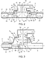
Figure 2 is a sectional view of a part of a spraying arm for a dishwasher according to an embodiment, -
Figure 3 is a sectional view of a part of a spraying arm for a dishwasher according to a further embodiment, -
Figure 4 is a diagrammatic view of the rotary-translation movement of the spraying arm inFigure 2 , -
Figure 5 is a diagrammatic view of the rotary-translation movement of the spraying arm inFigure 3 , -
Figure 6 is a diagrammatic view of the rotary-translation movement of the spraying arm according to a further embodiment, -
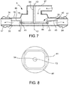
Figure 7 is a sectional view of a part of a spraying arm for a dishwasher according to a further embodiment, -
Figure 8 is a diagrammatic, top view of a cam track of the spraying arm inFigure 7 . - With reference to the Figures, a
dishwasher 1 comprises at least onewashing container 2 adapted to receivedishes 3 to be washed and closable by means of a door 4 (indicated inFigure 1 only diagrammatically, by means of a dashed line). - Inside the
dishwasher 1 at least one sprayingarm 5 is positioned, rotatably mounted in the washing container and forming a plurality of sprayingnozzles 6 for spraying a washing liquid on thedishes 3 received in thewashing container 2. Apump 7 is hydraulically connected, for example by means of asupply duct 8, with the sprayingarm 5 to feed the washing liquid to the sprayingnozzles 6. - The
dishwasher 1 further comprises aheating device 9 adapted to heat the washing liquid, for example an electrical resistor arranged in a washingliquid collection tank 10. Thecollection tank 10, preferably formed in a lower region of thewashing container 2 or below thewashing container 2, is connected with thepump 7 to allow the drawing of the cold or heated washing liquid required for the washing treatment of thedishes 3. Thecollection tank 10 and/or thepump 7 are further connected with aninlet valve 11 for loading mains water, and to a drainingduct 12 for draining the washing liquid. - The
dishwasher 1 further comprises control means, for example, anelectronic control unit 40, configured to allow the selection of a dish washing treatment program among a plurality of dish washing treatment programs, and to control the actuation of thepump 6, of theheating device 10 and of theinlet valve 11. - In a conventional manner, the one or more spraying
arms 5 may be put in rotation by virtue of an orientation of the sprayingnozzles 6, with at least one jet vector component in a direction tangential to the (vertical)rotation axis 13, and the consequent reaction force of the washing liquid jets produced by means of the pressure and the speed of the liquid conveyed by means of thepump 7. - Alternatively, the one or more spraying
arms 5 may be actuated in rotation by means of a rotary actuator, for example an electric motor or an electromechanic or electrohydraulic actuator. - The spraying
arm 5 comprises ahub portion 14 rotatably supported about arotation axis 13, and an elongated portion in the shape of abar 15 extending from thehub portion 14 in a direction transversal (preferably radial) to therotation axis 13, towards aninternal surface 16 of thewashing container 2. - The
bar portion 15 forms a plurality of sprayingnozzles 6 and is connected to thehub portion 14 so as to rotate together with thehub portion 14 about therotation axis 13. - According to an aspect of the invention, the
bar portion 15 comprises anend segment 17 which forms one or more of the sprayingnozzles 6 and which is translatable with respect to thehub portion 14 away from and towards therotation axis 13. The sprayingarm 5 further comprises asynchronization device 18 connected with thewashing container 2 and to theend segment 17 and configured to synchronize thetranslation movement 20 of theend segment 17 with therotary movement 21 of thehub portion 14 so as to translate theend segment 17 depending on the distance of theinternal surface 16 from the rotation axis 13 (Figures 4, 5, 6 ). - In particular, the
end segment 17 moves away from therotation axis 13 when thebar portion 15 is oriented towards thecorner regions 19 of thewashing container 2 which are further away from therotation axis 13, and theend segment 17 moves towards to therotation axis 13 when thebar portion 15 is oriented towards thewall regions 22 of thewashing container 2 which are closer to therotation axis 13. - Thereby, an automatic adjustment of the position and of the extension of the spraying
arm 5 to the change in distance between theinternal surface 16 of thewashing container 2 and therotation axis 13 of the sprayingarm 5 is obtained. As a result, the washing liquid is sprayed also on thedishes 3 arranged in the corner regions of the washing container 2 (Figures 4, 5, 6 ). - According to an embodiment, the
rotation axis 13 is substantially vertical and theinternal surface 16 is substantially rectangular, as shown inFigures 1 ,4, 5, 6 . - According to embodiments, the
bar portion 15 may extend on two opposite sides of thehub portion 14, may protrude in a direction substantially radial with respect to therotation axis 13, may lie and rotate on a plane substantially perpendicular to therotation axis 13 and may have a rectilinear development, possibly tapered towards the free ends. - Advantageously, the
hub portion 14 and thebar portion 15 and theend segment 17 may form one or more sprayingnozzles 6, so as ensure the most uniform possible washing liquid distribution. - According to an embodiment, the
spraying arm 5 comprises two translatable end segments 17 (forming the two radially outermost ends of the bar portion 15), arranged on two sides diametrically opposite (Figures 2 ,4 ) with respect to thehub portion 13 and translatable with respect to one another and with respect to thehub portion 14. Advantageously, thesynchronization device 18 is configured to make the twoend segments 17 translate with respect to thehub portion 14 in an alternate and opposing manner, and in a manner synchronized with the instantaneous orientation of the sprayingarm 5 with respect to thewashing container 2. - This allows a bilateral elongation and shortening of the spraying
arm 5, synchronized with the instantaneous orientation of the sprayingarm 5 with respect to the washing container 2 (Figure 4 ). - According to a further embodiment, the spraying
arm 5 comprises a single translatable end segment 17 (forming only one of the two radially outermost ends of the bar portion 15), translatable with respect to the hub portion 14 (Figures 3 ,5 ). In this case, thesynchronization device 18 may be configured to make the single translatingend segment 17 translate, with respect to thehub portion 14, in an alternating manner and synchronized with the instantaneous orientation of the sprayingarm 5 with respect to thewashing container 2. - This allows a unilateral elongation and shortening of the spraying
arm 5, synchronized with the instantaneous orientation of the spraying arm with respect to the washing container 2 (Figure 5 ). - According to a yet further embodiment, the spraying
arm 5 comprises twoend segments 17 firmly connected to one another and forming both the radially outermost ends of thebar portion 15 or forming theentire bar portion 15. The twoend segments 17 may be formed in a single piece or connected to one another so as to be translatable as a single body with respect to the hub portion 14 (Figure 6 ). In this embodiment, thesynchronization device 18 may be configured to make the twoend segments 17 together or theentire bar portion 15 translate with respect to thehub portion 14, in an alternating manner and synchronized with the instantaneous orientation of the sprayingarm 5 with respect to thewashing container 2. - This allows a rotary-translation of the spraying
arm 5, without changing the length thereof, in synchrony with the instantaneous orientation of the spraying arm with respect to the washing container 2 (Figure 6 ). - In an embodiment, the
synchronization device 18 is configured so as to translate the at least one translatable end segment 17: - in a protracted position at each passage through the
corner regions 19 of thewashing container 2, - in a retracted position at each passage through the
wall regions 22 of thewashing container 2. - This allows a greater washing liquid distribution frequency in the
corner regions 19, at the cost of greater friction and loss of energy due to the more frequent translations of theend segments 17. - Alternatively, the
synchronization device 18 is configured so as to translate the at least onetranslatable end segment 17 in the protracted position only at each nth passage through one of thecorner regions 19 of thewashing container 2, in which n > 1, preferably n = 2 or 3, and to translate or keep thetranslatable end segment 17 in the retracted position at each passage through one of thewall regions 22 of thewashing container 2. - This reduces the frictional resistance and energy losses due to the translations of the
end segments 17, at the cost of a lower washing liquid distribution frequency in thecorner regions 19. Obviously, in some cases, a lower spraying frequency is desired in the corner regions. - According to an embodiment, the spraying
arm 5 forms one or more sprayingnozzles 6, which: - with
end segment 17 in retracted position, are not fed with washing liquid or are only partially fed, and which - with
end segment 17 in protracted or extended position, are fed with washing liquid, - so as to increase the dispensing of the washing liquid with the increase of the length of the
spraying arm 5. - According to an embodiment, the
end segments 17 are slidably connected, for example, inserted telescopically with thehub portion 14 or with a radiallyinner portion 23, not translatable, of thebar portion 15. - For the waterproofing of the sliding or translatable connection between the
end segments 17 and thehub portion 14 or the radiallyinner portion 23, a sliding gasket interposed therebetween or abellow gasket 24 arranged around the sliding/translatable connection may be provided for (Figures 2, 3 ). - Advantageously, the
hub portion 14, thebar portion 15 and the translatable end segment/s 17 are hollow plastic profiles, preferably made of fiber-filled polymers, e.g., calcium- or talc-filled polypropylene. - According to an embodiment, the
synchronization device 18 comprises a purely mechanical synchronization transmission with at least onestationary reference member 25 which is stationary with respect to thewashing container 2, at least one alternatingmember 28 connected with the at least one translatingend segment 17, and asynchronization mechanism 29 connected with thehub portion 14, to the stationary reference member and to the alternatingmember 28 to synchronize their relative movements. - The
stationary reference member 25 may comprise, for example, a toothed wheel, a toothed crown, a pulley or a cam (Figures 2, 3 ), fixed and firmly connected to thewashing container 2. Advantageously, thestationary reference member 25 is fastened to anextractable dish rack 26 or directly to thewashing container 2, preferably together with (and inside) aduct portion 27 to which thehub portion 14 is rotatably coupled. - The
synchronization mechanism 29 may comprise a gear, a lever transmission, a cam or toothed belt transmission, or a crankshaft mechanism. - Preferably, the
synchronization mechanism 29 comprises: - a reduction or
multiplication mechanism 30, for example a gear, in connection between thehub portion 14 and thestationary reference member 25, and configured to make the desired ratio between an output motion frequency applied to the alternatingmember 28 and the rotation speed of thehub portion 14 with respect to thestationary reference member 25, - a
conversion mechanism 31, for example, a crank 32 androd 33 mechanism, connected between the reduction ormultiplication mechanism 30 and the alternating member 28 (in this case, therod 33 or the end thereof connected with theend segment 17 of the spraying arm 5), to convert the rotary output motion of the reduction/multiplication mechanism 30 into a reciprocating translation motion of the alternatingmember 28. -
Figure 2 shows aspraying arm 5 with asynchronization device 18 which actuates the reciprocating translation of twoopposite end segments 17, whileFigure 3 shows aspraying arm 5 with asynchronization device 18 which actuates the reciprocating translation of asingle end segment 17. - In the embodiment shown in
Figure 2 , thehub portion 14 is rotatably connected and in hydraulic communication with a fixedduct portion 27. Thestationary reference member 25 is a fixed toothed wheel (coaxial to the rotation axis 13), connected to a fixedshaft 34 extending from the inside of theduct portion 27 to the inside of thehub portion 14. - The de/
multiplication mechanism 30 comprises (on one single side or on two opposite sides of the rotation axis 13) arotatable shaft 36 supported in thehub portion 14 so as to rotate together with thehub portion 14 about therotation axis 13 and to be capable of rotating, with respect to thehub portion 14, about anown axis 37 spaced apart from therotation axis 13, as well as atoothed wheel 35 fastened on therotatable shaft 36 and meshed with the fixedtoothed wheel 25. - The
conversion mechanism 31 comprises (on one single side or on two opposite sides of the rotation axis 13) a crank 32 formed by or fastened on theshaft 36 and arod 33 connected between thecrank 32 and the translatingend segment 17. - This embodiment allows a synchronized translation, but not necessarily of identical frequency, of the two
end segments 17. - In the embodiment shown in
Figure 3 , thehub portion 14 is rotatably connected and in hydraulic communication with a fixedduct portion 27. Thestationary reference member 25 is a fixed toothed wheel (coaxial to the rotation axis 13), connected to a fixedshaft 34 extending from the inside of theduct portion 27 to the inside of thehub portion 14. - The de/
multiplication mechanism 30 comprises (on one single side of the rotation axis 13) arotatable shaft 36 supported in thehub portion 14 so as to rotate together with thehub portion 14 about therotation axis 13 and to be capable of rotating, with respect to thehub portion 14, about anown axis 37 spaced apart from therotation axis 13, as well as atoothed wheel 35 fastened on therotatable shaft 36 and meshing with the fixedtoothed wheel 25. On the samerotatable shaft 36, a furthertoothed wheel 38 is fastened, which meshes, by means of atoothed crown 39, a crank 32' rotatably supported on the fixedshaft 34. - The
conversion mechanism 31 comprises thecrank 32 supported on the fixedshaft 34 and arod 33 connected between thecrank 32 and the translatingend segment 17. -
Figure 7 shows aspraying arm 5 with asynchronization device 18 which actuates the reciprocating translation of twoopposite end segments 17, but which may even be used with a singletranslatable end segment 17. - In the embodiment shown in
Figure 7 , thehub portion 14 is rotatably connected and in hydraulic communication with a fixedduct portion 27. Thestationary reference member 25 is a fixedcam track 41, for example, connected to a fixedshaft 34 extending from the inside of theduct portion 27 to the inside of thehub portion 14. - The de/
multiplication mechanism 30 is implemented by means of the number of oscillations of thecam track 41 with respect to a circumference about therotation axis 13, in the present case, four oscillations corresponding to the fourcorner regions 19 of thewashing container 2. Theconversion mechanism 31 is implemented by the sliding engagement of a cam follower 42 (for example, equipped with a roller to reduce friction) which rotates together with thehub portion 14 about therotation axis 13 and which is fastened directly or by means of anextension bar 43 to the translatingend segment 17. - The
cam followers 42 of the twoend segments 17 may slide in asame cam track 41 or in two different cam tracks 41, made, for example, on two opposite faces (above-below) of acam plate 44. - Advantageously, the
synchronization device 18 is arranged inside the sprayingarm 5 and, possibly, partially inside a fixedduct portion 27 to which thespraying arm 5 is connected. More precisely, thesynchronization device 18 is arranged inside a hydraulic conveying space formed in thespraying arm 5 and, possibly, in the fixedduct portion 27. - This protects the synchronization device from external influences and ensures factory-set synchronization for the entire service life of the
spraying arm 5. - Obviously, further changes and variations to the
dishwasher 1 and thespraying arm 5 described so far may be introduced by those skilled in the art in order to meet contingent and specific needs, without thereby departing from the scope of protection of the invention as defined by the following claims.
Claims (15)
- A dishwasher (1), comprising:- a washing container (2) for receiving dishes (3) to be washed,- at least one spraying arm (5) rotatably mounted in the washing container (2) and forming a plurality of spraying nozzles (6) for spraying a washing liquid on the dishes in the washing container (2),- a pump (7) hydraulically connected with the spraying arm (5) to feed the washing liquid to the spraying nozzles (6),wherein the spraying arm (5) comprises:- a hub portion (14) rotatably supported about a rotation axis (13), and- a bar portion (15) extending from the hub portion (14) in a direction transversal to the rotation axis (13), towards an internal surface (16) of the washing container (2), wherein the bar portion (15) forms a plurality of said spraying nozzles (6) and is connected to the hub portion (14) so as to rotate together with the hub portion (14) about the rotation axis (13), characterized in that:- the bar portion comprises at least one end segment (17) translatable with respect to the hub portion (14) away from and towards the rotation axis (13),- the spraying arm (5) comprises a synchronization device (18) that synchronizes the translation movement of the end segment (17) with the rotary movement of the hub portion (14) so as to translate the end segment (17) depending on a distance between the internal surface (16) and the rotation axis (13).
- A dishwasher (1) according to claim 1, wherein said at least one end segment (17) is in a protracted position, away from the rotation axis (13) when the bar portion (15) is oriented towards corner regions (19) of the washing container (2), and the end segment (17) is in a retracted position towards the rotation axis (13) when the bar portion (15) is oriented towards wall regions (22) of the washing container (2) closer to the rotation axis (13) than the corner regions (19).
- A dishwasher (1) according to one of the previous claims, wherein the spraying arm (5) comprises two of said end segments (17) that form the two radially outermost ends of the bar portion (15) and that translate with respect to one another and with respect to the hub portion (14).
- A dishwasher (1) according to claim 3, wherein the synchronization device (18) is configured to make the two end segments (17) translate with respect to the hub portion (14) in an alternate and opposing manner.
- A dishwasher (1) according to one of claims 1 or 2, wherein the spraying arm (5) comprises a single end segment (17) forming only one of the two radially outermost ends of the bar portion (15) and translatable with respect to the hub portion (14).
- A dishwasher (1) according to one of claims 1 or 2, wherein the spraying arm (5) comprises two end segments (17) firmly connected to one another and that both form the radially outermost ends of the bar portion (15) or that form the entire bar portion (15), wherein said two end segments (17) translate as a single body with respect to the hub portion (14).
- A dishwasher (1) according to one of the previous claims, wherein the spraying arm (5) forms one or more spraying nozzles (6) that:- with end segment (17) in retracted position, are not fed with washing liquid or are only partially fed, and- with end segment (17) in protracted position, are fed with washing liquid.
- A dishwasher (1) according to one of the previous claims, wherein the end segments (17) are inserted telescopically with the hub portion (14) or with a radially inner portion (23), not translatable, of the bar portion (15).
- A dishwasher (1) according to one of the previous claims, wherein in a connection area between the end segments (17) and the hub portion (14) a bellow gasket (24) is formed.
- A dishwasher (1) according to one of the previous claims, wherein the synchronization device (18) comprises a purely mechanical synchronization transmission with at least one stationary reference member (25) that is stationary with respect to the washing container (2), at least one alternating member (28) connected with the at least one translating end segment (17), and a synchronization mechanism (29) connected with the hub portion (14), with the stationary reference member (25) and with the alternating member (28) to synchronize their relative movements.
- A dishwasher (1) according to claim 10, wherein:- the stationary reference member (25) is selected in the group consisting of:- a toothed wheel,- a toothed crown,- a pulley,- a cam,fixed and firmly connected with the washing container (2) or with a dish rack (26) supported in an extractable manner in the washing container (2).- the synchronization mechanism (29) is selected from the group consisting of:- a gear,- a lever transmission,- a cam transmission,- a toothed belt transmission,- a crankshaft mechanism.
- A dishwasher (1) according to claim 10 or 11, wherein the synchronization mechanism (29) comprises:- a de/multiplication mechanism (30) connected to the hub portion (14) and that interacts with the stationary reference member (25), to make the desired ratio between an output motion frequency applied to the alternating member (28) and the rotation speed of the hub portion (14) with respect to the stationary reference member (25),- a conversion mechanism (31) connected between the de/multiplication mechanism (30) and the alternating member (28) to convert the rotary output motion of the de/multiplication mechanism (30) into a reciprocating translation motion of the alternating member (28).
- A dishwasher (1) according to one of the previous claims, wherein the synchronization device (18) is arranged inside a hydraulic conveying space formed in the spraying arm (5) and extending in a fixed duct portion (27) to which the spraying arm (5) is connected.
- A dishwasher (1) according to one of the previous claims, wherein the hub portion (14), the bar portion (15) and the translatable end segment (17) are hollow plastic profiles.
- A dishwasher (1) according to one of the previous claims, wherein:- the rotation axis (13) is substantially vertical and the internal surface (16) is substantially rectangular, and/or the bar portion (15) extends on two opposite sides of the hub portion (14), projects in a substantially radial direction with respect to the rotation axis (13) and rotates in a plane substantially perpendicular to the rotation axis (13), and/or the hub portion (14) and the bar portion (15) and the end segment (17) form one or more of the spraying nozzles (6).
Applications Claiming Priority (1)
| Application Number | Priority Date | Filing Date | Title |
|---|---|---|---|
| IT102017000031111A IT201700031111A1 (en) | 2017-03-21 | 2017-03-21 | Dishwasher machine with rotary-moving spray arm |
Publications (2)
| Publication Number | Publication Date |
|---|---|
| EP3378370A1 true EP3378370A1 (en) | 2018-09-26 |
| EP3378370B1 EP3378370B1 (en) | 2021-03-31 |
Family
ID=59521540
Family Applications (1)
| Application Number | Title | Priority Date | Filing Date |
|---|---|---|---|
| EP18162180.6A Active EP3378370B1 (en) | 2017-03-21 | 2018-03-16 | Dishwasher with rotary-translating spraying arm |
Country Status (5)
| Country | Link |
|---|---|
| EP (1) | EP3378370B1 (en) |
| CN (1) | CN108618725B (en) |
| ES (1) | ES2877584T3 (en) |
| IT (1) | IT201700031111A1 (en) |
| RU (1) | RU2765734C2 (en) |
Cited By (5)
| Publication number | Priority date | Publication date | Assignee | Title |
|---|---|---|---|---|
| CN109674414A (en) * | 2019-01-24 | 2019-04-26 | 北京米浪科技有限公司 | Washing facility |
| CN110960165A (en) * | 2018-09-30 | 2020-04-07 | 青岛海尔智能技术研发有限公司 | Dish washer spraying assembly and dish washer |
| CN110960166A (en) * | 2018-09-30 | 2020-04-07 | 青岛海尔智能技术研发有限公司 | Dish washer spraying assembly and dish washer |
| EP3766400A1 (en) * | 2019-07-08 | 2021-01-20 | Vestel Beyaz Esya Sanayi Ve Ticaret A.S. | A spray arrangement for dishwashers |
| EP3881746A1 (en) * | 2020-03-19 | 2021-09-22 | Vestel Beyaz Esya Sanayi Ve Ticaret A.S. | A sprinkler device for dishwashers |
Families Citing this family (4)
| Publication number | Priority date | Publication date | Assignee | Title |
|---|---|---|---|---|
| CN107115079B (en) * | 2017-07-16 | 2019-07-12 | 宁波凯瑞博人力资源管理服务有限公司 | Spraying head capable of automatically changing direction for dish washing machine and dish washing machine with spraying head |
| DE102019211403A1 (en) * | 2019-07-31 | 2021-02-04 | BSH Hausgeräte GmbH | Household dishwasher |
| CN111870203B (en) * | 2020-07-22 | 2023-04-07 | 苏州科洁泰电器有限公司 | Spraying structure of dish-washing machine |
| EP3967207A1 (en) * | 2020-09-14 | 2022-03-16 | Electrolux Professional S.p.A. | Dishwasher |
Citations (6)
| Publication number | Priority date | Publication date | Assignee | Title |
|---|---|---|---|---|
| DE8114533U1 (en) * | 1981-05-16 | 1981-08-13 | Licentia Patent-Verwaltungs-Gmbh, 6000 Frankfurt | DISHWASHER WITH A HEIGHT-ADJUSTABLE DISH BASKET |
| EP0727177A2 (en) * | 1995-02-15 | 1996-08-21 | SMEG S.p.A. | Revolving sprinkling assembly for dishwashers, provided with horizontal reciprocating motion |
| GB2314009A (en) * | 1996-06-14 | 1997-12-17 | Daewoo Electronics Co Ltd | Dispersing washing water of a dishwasher |
| EP0836829A2 (en) * | 1996-10-16 | 1998-04-22 | Samsung Electronics Co., Ltd. | Dishwasher |
| EP1090579A1 (en) * | 1999-10-01 | 2001-04-11 | SMEG S.p.A. | Revolving sprinkling assembly for dishwasher provided with a device for horizontal shift |
| KR20070066340A (en) * | 2005-12-21 | 2007-06-27 | 주식회사 대우일렉트로닉스 | Dispenser of dishwasher |
Family Cites Families (10)
| Publication number | Priority date | Publication date | Assignee | Title |
|---|---|---|---|---|
| US4509687A (en) * | 1983-07-20 | 1985-04-09 | General Electric Company | Multiple spray distribution system for a domestic dishwasher |
| CN1207284A (en) * | 1998-04-28 | 1999-02-10 | 卢杲 | Dishwasher |
| CN2369625Y (en) * | 1999-01-12 | 2000-03-22 | 姚凌 | Cleaning machine for vegetable fruits and dining utensils |
| EP2279687B1 (en) * | 2009-07-28 | 2011-09-21 | Electrolux Home Products Corporation N.V. | Spray arm arrangement for a dishwasher |
| CN202122562U (en) * | 2011-07-06 | 2012-01-25 | 李创健 | Device in household dish washer for washing dinnerware |
| FR3031331B1 (en) * | 2015-01-05 | 2017-07-14 | Valeo Systemes Dessuyage | WIPER ARM EQUIPPED WITH SPRAY |
| CN104605800A (en) * | 2015-02-16 | 2015-05-13 | 桂林我爱你科技开发有限公司 | Swinging-type jet washing machine of dishwasher |
| CN104814710B (en) * | 2015-05-26 | 2018-02-06 | 佛山市顺德区美的洗涤电器制造有限公司 | Spray arm component and there is its dish-washing machine |
| CN105286752B (en) * | 2015-11-20 | 2018-10-26 | 佛山市顺德区美的洗涤电器制造有限公司 | For the gushing arm component of dish-washing machine and with its dish-washing machine |
| CN106308716B (en) * | 2016-09-05 | 2019-07-02 | 佛山市顺德区美的洗涤电器制造有限公司 | Dishwasher spray arm assembly |
-
2017
- 2017-03-21 IT IT102017000031111A patent/IT201700031111A1/en unknown
-
2018
- 2018-03-16 ES ES18162180T patent/ES2877584T3/en active Active
- 2018-03-16 EP EP18162180.6A patent/EP3378370B1/en active Active
- 2018-03-20 CN CN201810228413.3A patent/CN108618725B/en active Active
- 2018-03-20 RU RU2018109580A patent/RU2765734C2/en active
Patent Citations (6)
| Publication number | Priority date | Publication date | Assignee | Title |
|---|---|---|---|---|
| DE8114533U1 (en) * | 1981-05-16 | 1981-08-13 | Licentia Patent-Verwaltungs-Gmbh, 6000 Frankfurt | DISHWASHER WITH A HEIGHT-ADJUSTABLE DISH BASKET |
| EP0727177A2 (en) * | 1995-02-15 | 1996-08-21 | SMEG S.p.A. | Revolving sprinkling assembly for dishwashers, provided with horizontal reciprocating motion |
| GB2314009A (en) * | 1996-06-14 | 1997-12-17 | Daewoo Electronics Co Ltd | Dispersing washing water of a dishwasher |
| EP0836829A2 (en) * | 1996-10-16 | 1998-04-22 | Samsung Electronics Co., Ltd. | Dishwasher |
| EP1090579A1 (en) * | 1999-10-01 | 2001-04-11 | SMEG S.p.A. | Revolving sprinkling assembly for dishwasher provided with a device for horizontal shift |
| KR20070066340A (en) * | 2005-12-21 | 2007-06-27 | 주식회사 대우일렉트로닉스 | Dispenser of dishwasher |
Cited By (7)
| Publication number | Priority date | Publication date | Assignee | Title |
|---|---|---|---|---|
| CN110960165A (en) * | 2018-09-30 | 2020-04-07 | 青岛海尔智能技术研发有限公司 | Dish washer spraying assembly and dish washer |
| CN110960166A (en) * | 2018-09-30 | 2020-04-07 | 青岛海尔智能技术研发有限公司 | Dish washer spraying assembly and dish washer |
| CN110960166B (en) * | 2018-09-30 | 2023-08-18 | 青岛海尔智能技术研发有限公司 | Spraying assembly of dish washing machine and dish washing machine |
| CN110960165B (en) * | 2018-09-30 | 2023-08-22 | 青岛海尔智能技术研发有限公司 | Dishwasher spray assembly and dishwasher |
| CN109674414A (en) * | 2019-01-24 | 2019-04-26 | 北京米浪科技有限公司 | Washing facility |
| EP3766400A1 (en) * | 2019-07-08 | 2021-01-20 | Vestel Beyaz Esya Sanayi Ve Ticaret A.S. | A spray arrangement for dishwashers |
| EP3881746A1 (en) * | 2020-03-19 | 2021-09-22 | Vestel Beyaz Esya Sanayi Ve Ticaret A.S. | A sprinkler device for dishwashers |
Also Published As
| Publication number | Publication date |
|---|---|
| CN108618725B (en) | 2023-03-24 |
| RU2018109580A (en) | 2019-09-23 |
| RU2018109580A3 (en) | 2021-07-06 |
| EP3378370B1 (en) | 2021-03-31 |
| ES2877584T3 (en) | 2021-11-17 |
| CN108618725A (en) | 2018-10-09 |
| IT201700031111A1 (en) | 2018-09-21 |
| RU2765734C2 (en) | 2022-02-02 |
Similar Documents
| Publication | Publication Date | Title |
|---|---|---|
| EP3378370B1 (en) | Dishwasher with rotary-translating spraying arm | |
| AU2016304607B2 (en) | Hinge device with long reciprocating stroke of a front panel | |
| EP2772176B1 (en) | Dishwasher with hydraulically driven sprayer | |
| EP3900605B1 (en) | Dish-washing machine and spraying mechanism | |
| EP3082552A1 (en) | Arrangement in a dishwasher for creating a wash zone with intensified washing | |
| CN105877477A (en) | Pressure cooking utensil capable of opening and closing cover conveniently | |
| CN209076966U (en) | A kind of processing unit (plant) for truck drive shaft | |
| CN109114606B (en) | Food processor | |
| CN109419298B (en) | Cooking utensil | |
| EP3135180B1 (en) | A dishwasher comprising a liquid/gel dosing unit | |
| CN209693862U (en) | Automatic thin-pancake maker | |
| CN209863718U (en) | Dish washer and spray mechanism | |
| CN208991073U (en) | A kind of vacuum spray painting machine with positioning spraying function | |
| CN105082324B (en) | Crockery intelligence roller head machine | |
| CN202714736U (en) | Baking oven structure | |
| CN208228784U (en) | Cooking apparatus | |
| CN217185634U (en) | Energy-saving environment-friendly frequency conversion steaming cabinet | |
| CN110916517B (en) | A kind of automatic rice cooker and control method thereof | |
| CN209235727U (en) | Steam valve and cooking utensil | |
| CN109864622B (en) | Embedded kitchen material reason machine | |
| EP3040013A1 (en) | Household appliances heating method and related washing machine | |
| EP3796826B1 (en) | A dishwasher comprising spray arm | |
| WO2018024579A1 (en) | Infuser unit for a coffee machine | |
| CN210625250U (en) | Guiding mechanism of drying-machine of processing dacron surface fabric | |
| CN220778308U (en) | Dish-washing machine |
Legal Events
| Date | Code | Title | Description |
|---|---|---|---|
| PUAI | Public reference made under article 153(3) epc to a published international application that has entered the european phase |
Free format text: ORIGINAL CODE: 0009012 |
|
| STAA | Information on the status of an ep patent application or granted ep patent |
Free format text: STATUS: THE APPLICATION HAS BEEN PUBLISHED |
|
| AK | Designated contracting states |
Kind code of ref document: A1 Designated state(s): AL AT BE BG CH CY CZ DE DK EE ES FI FR GB GR HR HU IE IS IT LI LT LU LV MC MK MT NL NO PL PT RO RS SE SI SK SM TR |
|
| AX | Request for extension of the european patent |
Extension state: BA ME |
|
| STAA | Information on the status of an ep patent application or granted ep patent |
Free format text: STATUS: REQUEST FOR EXAMINATION WAS MADE |
|
| 17P | Request for examination filed |
Effective date: 20190207 |
|
| RBV | Designated contracting states (corrected) |
Designated state(s): AL AT BE BG CH CY CZ DE DK EE ES FI FR GB GR HR HU IE IS IT LI LT LU LV MC MK MT NL NO PL PT RO RS SE SI SK SM TR |
|
| STAA | Information on the status of an ep patent application or granted ep patent |
Free format text: STATUS: EXAMINATION IS IN PROGRESS |
|
| 17Q | First examination report despatched |
Effective date: 20200526 |
|
| GRAP | Despatch of communication of intention to grant a patent |
Free format text: ORIGINAL CODE: EPIDOSNIGR1 |
|
| STAA | Information on the status of an ep patent application or granted ep patent |
Free format text: STATUS: GRANT OF PATENT IS INTENDED |
|
| INTG | Intention to grant announced |
Effective date: 20201201 |
|
| RAP1 | Party data changed (applicant data changed or rights of an application transferred) |
Owner name: CANDY S.P.A. |
|
| RIN1 | Information on inventor provided before grant (corrected) |
Inventor name: FUMAGALLI, ALDO |
|
| GRAS | Grant fee paid |
Free format text: ORIGINAL CODE: EPIDOSNIGR3 |
|
| GRAA | (expected) grant |
Free format text: ORIGINAL CODE: 0009210 |
|
| STAA | Information on the status of an ep patent application or granted ep patent |
Free format text: STATUS: THE PATENT HAS BEEN GRANTED |
|
| AK | Designated contracting states |
Kind code of ref document: B1 Designated state(s): AL AT BE BG CH CY CZ DE DK EE ES FI FR GB GR HR HU IE IS IT LI LT LU LV MC MK MT NL NO PL PT RO RS SE SI SK SM TR |
|
| REG | Reference to a national code |
Ref country code: GB Ref legal event code: FG4D Ref country code: CH Ref legal event code: EP |
|
| REG | Reference to a national code |
Ref country code: DE Ref legal event code: R096 Ref document number: 602018014570 Country of ref document: DE Ref country code: AT Ref legal event code: REF Ref document number: 1375981 Country of ref document: AT Kind code of ref document: T Effective date: 20210415 |
|
| REG | Reference to a national code |
Ref country code: IE Ref legal event code: FG4D |
|
| REG | Reference to a national code |
Ref country code: LT Ref legal event code: MG9D |
|
| PG25 | Lapsed in a contracting state [announced via postgrant information from national office to epo] |
Ref country code: NO Free format text: LAPSE BECAUSE OF FAILURE TO SUBMIT A TRANSLATION OF THE DESCRIPTION OR TO PAY THE FEE WITHIN THE PRESCRIBED TIME-LIMIT Effective date: 20210630 Ref country code: FI Free format text: LAPSE BECAUSE OF FAILURE TO SUBMIT A TRANSLATION OF THE DESCRIPTION OR TO PAY THE FEE WITHIN THE PRESCRIBED TIME-LIMIT Effective date: 20210331 Ref country code: HR Free format text: LAPSE BECAUSE OF FAILURE TO SUBMIT A TRANSLATION OF THE DESCRIPTION OR TO PAY THE FEE WITHIN THE PRESCRIBED TIME-LIMIT Effective date: 20210331 Ref country code: BG Free format text: LAPSE BECAUSE OF FAILURE TO SUBMIT A TRANSLATION OF THE DESCRIPTION OR TO PAY THE FEE WITHIN THE PRESCRIBED TIME-LIMIT Effective date: 20210630 |
|
| PG25 | Lapsed in a contracting state [announced via postgrant information from national office to epo] |
Ref country code: SE Free format text: LAPSE BECAUSE OF FAILURE TO SUBMIT A TRANSLATION OF THE DESCRIPTION OR TO PAY THE FEE WITHIN THE PRESCRIBED TIME-LIMIT Effective date: 20210331 Ref country code: RS Free format text: LAPSE BECAUSE OF FAILURE TO SUBMIT A TRANSLATION OF THE DESCRIPTION OR TO PAY THE FEE WITHIN THE PRESCRIBED TIME-LIMIT Effective date: 20210331 Ref country code: LV Free format text: LAPSE BECAUSE OF FAILURE TO SUBMIT A TRANSLATION OF THE DESCRIPTION OR TO PAY THE FEE WITHIN THE PRESCRIBED TIME-LIMIT Effective date: 20210331 |
|
| REG | Reference to a national code |
Ref country code: NL Ref legal event code: MP Effective date: 20210331 |
|
| REG | Reference to a national code |
Ref country code: AT Ref legal event code: MK05 Ref document number: 1375981 Country of ref document: AT Kind code of ref document: T Effective date: 20210331 |
|
| PG25 | Lapsed in a contracting state [announced via postgrant information from national office to epo] |
Ref country code: NL Free format text: LAPSE BECAUSE OF FAILURE TO SUBMIT A TRANSLATION OF THE DESCRIPTION OR TO PAY THE FEE WITHIN THE PRESCRIBED TIME-LIMIT Effective date: 20210331 Ref country code: SM Free format text: LAPSE BECAUSE OF FAILURE TO SUBMIT A TRANSLATION OF THE DESCRIPTION OR TO PAY THE FEE WITHIN THE PRESCRIBED TIME-LIMIT Effective date: 20210331 Ref country code: AT Free format text: LAPSE BECAUSE OF FAILURE TO SUBMIT A TRANSLATION OF THE DESCRIPTION OR TO PAY THE FEE WITHIN THE PRESCRIBED TIME-LIMIT Effective date: 20210331 Ref country code: CZ Free format text: LAPSE BECAUSE OF FAILURE TO SUBMIT A TRANSLATION OF THE DESCRIPTION OR TO PAY THE FEE WITHIN THE PRESCRIBED TIME-LIMIT Effective date: 20210331 Ref country code: EE Free format text: LAPSE BECAUSE OF FAILURE TO SUBMIT A TRANSLATION OF THE DESCRIPTION OR TO PAY THE FEE WITHIN THE PRESCRIBED TIME-LIMIT Effective date: 20210331 Ref country code: LT Free format text: LAPSE BECAUSE OF FAILURE TO SUBMIT A TRANSLATION OF THE DESCRIPTION OR TO PAY THE FEE WITHIN THE PRESCRIBED TIME-LIMIT Effective date: 20210331 |
|
| REG | Reference to a national code |
Ref country code: ES Ref legal event code: FG2A Ref document number: 2877584 Country of ref document: ES Kind code of ref document: T3 Effective date: 20211117 |
|
| PG25 | Lapsed in a contracting state [announced via postgrant information from national office to epo] |
Ref country code: IS Free format text: LAPSE BECAUSE OF FAILURE TO SUBMIT A TRANSLATION OF THE DESCRIPTION OR TO PAY THE FEE WITHIN THE PRESCRIBED TIME-LIMIT Effective date: 20210731 Ref country code: PL Free format text: LAPSE BECAUSE OF FAILURE TO SUBMIT A TRANSLATION OF THE DESCRIPTION OR TO PAY THE FEE WITHIN THE PRESCRIBED TIME-LIMIT Effective date: 20210331 Ref country code: PT Free format text: LAPSE BECAUSE OF FAILURE TO SUBMIT A TRANSLATION OF THE DESCRIPTION OR TO PAY THE FEE WITHIN THE PRESCRIBED TIME-LIMIT Effective date: 20210802 Ref country code: RO Free format text: LAPSE BECAUSE OF FAILURE TO SUBMIT A TRANSLATION OF THE DESCRIPTION OR TO PAY THE FEE WITHIN THE PRESCRIBED TIME-LIMIT Effective date: 20210331 Ref country code: SK Free format text: LAPSE BECAUSE OF FAILURE TO SUBMIT A TRANSLATION OF THE DESCRIPTION OR TO PAY THE FEE WITHIN THE PRESCRIBED TIME-LIMIT Effective date: 20210331 |
|
| REG | Reference to a national code |
Ref country code: DE Ref legal event code: R097 Ref document number: 602018014570 Country of ref document: DE |
|
| PG25 | Lapsed in a contracting state [announced via postgrant information from national office to epo] |
Ref country code: AL Free format text: LAPSE BECAUSE OF FAILURE TO SUBMIT A TRANSLATION OF THE DESCRIPTION OR TO PAY THE FEE WITHIN THE PRESCRIBED TIME-LIMIT Effective date: 20210331 Ref country code: DK Free format text: LAPSE BECAUSE OF FAILURE TO SUBMIT A TRANSLATION OF THE DESCRIPTION OR TO PAY THE FEE WITHIN THE PRESCRIBED TIME-LIMIT Effective date: 20210331 |
|
| PLBE | No opposition filed within time limit |
Free format text: ORIGINAL CODE: 0009261 |
|
| STAA | Information on the status of an ep patent application or granted ep patent |
Free format text: STATUS: NO OPPOSITION FILED WITHIN TIME LIMIT |
|
| 26N | No opposition filed |
Effective date: 20220104 |
|
| PG25 | Lapsed in a contracting state [announced via postgrant information from national office to epo] |
Ref country code: IS Free format text: LAPSE BECAUSE OF FAILURE TO SUBMIT A TRANSLATION OF THE DESCRIPTION OR TO PAY THE FEE WITHIN THE PRESCRIBED TIME-LIMIT Effective date: 20210731 |
|
| PG25 | Lapsed in a contracting state [announced via postgrant information from national office to epo] |
Ref country code: MC Free format text: LAPSE BECAUSE OF FAILURE TO SUBMIT A TRANSLATION OF THE DESCRIPTION OR TO PAY THE FEE WITHIN THE PRESCRIBED TIME-LIMIT Effective date: 20210331 |
|
| REG | Reference to a national code |
Ref country code: CH Ref legal event code: PL |
|
| REG | Reference to a national code |
Ref country code: BE Ref legal event code: MM Effective date: 20220331 |
|
| PG25 | Lapsed in a contracting state [announced via postgrant information from national office to epo] |
Ref country code: LU Free format text: LAPSE BECAUSE OF NON-PAYMENT OF DUE FEES Effective date: 20220316 Ref country code: LI Free format text: LAPSE BECAUSE OF NON-PAYMENT OF DUE FEES Effective date: 20220331 Ref country code: IE Free format text: LAPSE BECAUSE OF NON-PAYMENT OF DUE FEES Effective date: 20220316 Ref country code: CH Free format text: LAPSE BECAUSE OF NON-PAYMENT OF DUE FEES Effective date: 20220331 |
|
| PG25 | Lapsed in a contracting state [announced via postgrant information from national office to epo] |
Ref country code: BE Free format text: LAPSE BECAUSE OF NON-PAYMENT OF DUE FEES Effective date: 20220331 |
|
| PG25 | Lapsed in a contracting state [announced via postgrant information from national office to epo] |
Ref country code: HU Free format text: LAPSE BECAUSE OF FAILURE TO SUBMIT A TRANSLATION OF THE DESCRIPTION OR TO PAY THE FEE WITHIN THE PRESCRIBED TIME-LIMIT; INVALID AB INITIO Effective date: 20180316 |
|
| PG25 | Lapsed in a contracting state [announced via postgrant information from national office to epo] |
Ref country code: MK Free format text: LAPSE BECAUSE OF FAILURE TO SUBMIT A TRANSLATION OF THE DESCRIPTION OR TO PAY THE FEE WITHIN THE PRESCRIBED TIME-LIMIT Effective date: 20210331 Ref country code: CY Free format text: LAPSE BECAUSE OF FAILURE TO SUBMIT A TRANSLATION OF THE DESCRIPTION OR TO PAY THE FEE WITHIN THE PRESCRIBED TIME-LIMIT Effective date: 20210331 |
|
| PG25 | Lapsed in a contracting state [announced via postgrant information from national office to epo] |
Ref country code: MT Free format text: LAPSE BECAUSE OF FAILURE TO SUBMIT A TRANSLATION OF THE DESCRIPTION OR TO PAY THE FEE WITHIN THE PRESCRIBED TIME-LIMIT Effective date: 20210331 |
|
| PG25 | Lapsed in a contracting state [announced via postgrant information from national office to epo] |
Ref country code: GR Free format text: LAPSE BECAUSE OF NON-PAYMENT OF DUE FEES Effective date: 20210331 |
|
| REG | Reference to a national code |
Ref country code: DE Ref legal event code: R081 Ref document number: 602018014570 Country of ref document: DE Owner name: CANDY S.P.A., IT Free format text: FORMER OWNER: CANDY S.P.A., MONZA, IT |
|
| PG25 | Lapsed in a contracting state [announced via postgrant information from national office to epo] |
Ref country code: GR Free format text: LAPSE BECAUSE OF NON-PAYMENT OF DUE FEES Effective date: 20210331 |
|
| PGFP | Annual fee paid to national office [announced via postgrant information from national office to epo] |
Ref country code: ES Payment date: 20250402 Year of fee payment: 8 |
|
| PGFP | Annual fee paid to national office [announced via postgrant information from national office to epo] |
Ref country code: GB Payment date: 20260324 Year of fee payment: 9 |
|
| PGFP | Annual fee paid to national office [announced via postgrant information from national office to epo] |
Ref country code: DE Payment date: 20260325 Year of fee payment: 9 |
|
| PGFP | Annual fee paid to national office [announced via postgrant information from national office to epo] |
Ref country code: IT Payment date: 20260123 Year of fee payment: 9 |
|
| PGFP | Annual fee paid to national office [announced via postgrant information from national office to epo] |
Ref country code: FR Payment date: 20260227 Year of fee payment: 9 |
|
| PGFP | Annual fee paid to national office [announced via postgrant information from national office to epo] |
Ref country code: TR Payment date: 20260314 Year of fee payment: 9 |