EP3378342B1 - Schutzelement für einem kleidungsstück - Google Patents
Schutzelement für einem kleidungsstück Download PDFInfo
- Publication number
- EP3378342B1 EP3378342B1 EP18172477.4A EP18172477A EP3378342B1 EP 3378342 B1 EP3378342 B1 EP 3378342B1 EP 18172477 A EP18172477 A EP 18172477A EP 3378342 B1 EP3378342 B1 EP 3378342B1
- Authority
- EP
- European Patent Office
- Prior art keywords
- component
- plate
- material layer
- cushioning
- plate component
- Prior art date
- Legal status (The legal status is an assumption and is not a legal conclusion. Google has not performed a legal analysis and makes no representation as to the accuracy of the status listed.)
- Active
Links
Images


Classifications
-
- A—HUMAN NECESSITIES
- A41—WEARING APPAREL
- A41D—OUTERWEAR; PROTECTIVE GARMENTS; ACCESSORIES
- A41D13/00—Professional, industrial or sporting protective garments, e.g. surgeons' gowns or garments protecting against blows or punches
- A41D13/05—Professional, industrial or sporting protective garments, e.g. surgeons' gowns or garments protecting against blows or punches protecting only a particular body part
- A41D13/055—Protector fastening, e.g. on the human body
- A41D13/0556—Protector fastening, e.g. on the human body with releasable fastening means
- A41D13/0562—Protector fastening, e.g. on the human body with releasable fastening means with hook and loop fastener
-
- A—HUMAN NECESSITIES
- A63—SPORTS; GAMES; AMUSEMENTS
- A63B—APPARATUS FOR PHYSICAL TRAINING, GYMNASTICS, SWIMMING, CLIMBING, OR FENCING; BALL GAMES; TRAINING EQUIPMENT
- A63B71/00—Games or sports accessories not covered in groups A63B1/00 - A63B69/00
- A63B71/08—Body-protectors for players or sportsmen, i.e. body-protecting accessories affording protection of body parts against blows or collisions
- A63B71/12—Body-protectors for players or sportsmen, i.e. body-protecting accessories affording protection of body parts against blows or collisions for the body or the legs, e.g. for the shoulders
- A63B71/1225—Body-protectors for players or sportsmen, i.e. body-protecting accessories affording protection of body parts against blows or collisions for the body or the legs, e.g. for the shoulders for the legs, e.g. thighs, knees, ankles, feet
- A63B2071/1233—Body-protectors for players or sportsmen, i.e. body-protecting accessories affording protection of body parts against blows or collisions for the body or the legs, e.g. for the shoulders for the legs, e.g. thighs, knees, ankles, feet for the hip
-
- A—HUMAN NECESSITIES
- A63—SPORTS; GAMES; AMUSEMENTS
- A63B—APPARATUS FOR PHYSICAL TRAINING, GYMNASTICS, SWIMMING, CLIMBING, OR FENCING; BALL GAMES; TRAINING EQUIPMENT
- A63B71/00—Games or sports accessories not covered in groups A63B1/00 - A63B69/00
- A63B71/08—Body-protectors for players or sportsmen, i.e. body-protecting accessories affording protection of body parts against blows or collisions
- A63B71/12—Body-protectors for players or sportsmen, i.e. body-protecting accessories affording protection of body parts against blows or collisions for the body or the legs, e.g. for the shoulders
- A63B71/1225—Body-protectors for players or sportsmen, i.e. body-protecting accessories affording protection of body parts against blows or collisions for the body or the legs, e.g. for the shoulders for the legs, e.g. thighs, knees, ankles, feet
- A63B2071/1241—Body-protectors for players or sportsmen, i.e. body-protecting accessories affording protection of body parts against blows or collisions for the body or the legs, e.g. for the shoulders for the legs, e.g. thighs, knees, ankles, feet for the thigh
-
- A—HUMAN NECESSITIES
- A63—SPORTS; GAMES; AMUSEMENTS
- A63B—APPARATUS FOR PHYSICAL TRAINING, GYMNASTICS, SWIMMING, CLIMBING, OR FENCING; BALL GAMES; TRAINING EQUIPMENT
- A63B2243/00—Specific ball sports not provided for in A63B2102/00 - A63B2102/38
- A63B2243/0066—Rugby; American football
- A63B2243/007—American football
-
- A—HUMAN NECESSITIES
- A63—SPORTS; GAMES; AMUSEMENTS
- A63B—APPARATUS FOR PHYSICAL TRAINING, GYMNASTICS, SWIMMING, CLIMBING, OR FENCING; BALL GAMES; TRAINING EQUIPMENT
- A63B71/00—Games or sports accessories not covered in groups A63B1/00 - A63B69/00
- A63B71/08—Body-protectors for players or sportsmen, i.e. body-protecting accessories affording protection of body parts against blows or collisions
- A63B71/12—Body-protectors for players or sportsmen, i.e. body-protecting accessories affording protection of body parts against blows or collisions for the body or the legs, e.g. for the shoulders
- A63B71/1225—Body-protectors for players or sportsmen, i.e. body-protecting accessories affording protection of body parts against blows or collisions for the body or the legs, e.g. for the shoulders for the legs, e.g. thighs, knees, ankles, feet
Definitions
- Articles of athletic apparel commonly incorporate elements that cushion or protect an athlete from contact with other athletes, equipment, or the ground.
- the protective elements include multiple layers of dissimilar materials, attaching the layers together may be time consuming and require expensive manual labor. Therefore, there is a need in the art for new designs for protective elements and methods of making the protective elements.
- Protective elements for an article of apparel include a plate component and a cushioning component that are secured together by stitching which passes through a thinned portion of the plate component.
- the thinned portion extends around a periphery of the plate component, and may be co-formed with the molding of the plate or formed after the making of the plate by removing a portion of the edge material of the plate.
- An attachment element may be passed through the attachment area and at least one layer of the cushioning component thereby attaching the plate component to at least the one layer.
- the cushioning component includes a pair of material layers and at least one pad located between the material layers.
- the plate component is typically made of a polymer material and the pad may include a polymer foam material.
- the plate element has greater rigidity than the cushioning material of the pads.
- US 2011/0277226 A1 discloses a protective element for an article of apparel, including a plate element and a cushioning element that are secured together with a hook-and-loop fastening system.
- the cushioning system includes a pair of material layers and a pad located between the material layers.
- the plate element may be easily separated, repositioned or replaced with another plate having a different configuration.
- the invention provides a protective element for an article of apparel including a plate component having a perimeter shape.
- the protective element includes a first material layer having an exterior surface and an opposing interior surface. The exterior surface is positioned adjacent to the plate component.
- a pad component having a first surface is positioned adjacent to an interior of the first material layer.
- a guide pattern is disposed on the exterior surface of the first material layer opposite the interior adjacent the pad component. The guide pattern corresponds to the perimeter shape of the plate component.
- the plate component is positioned on the first material layer using the guide pattern.
- An attachment element attaches the plate component to the first material layer proximate the guide pattern, wherein the attachment element is a hook-and-loop type attachment.
- the protective elements generally include a plate component and a cushioning component that are secured together by stitching or staples that pass through a thinned portion of the plate.
- the thinned portion extends around a periphery of the plate, and may be co-formed with the molding of the plate or formed after the making of the plate by removing a portion of the edge material of the plate.
- the stitching or staples may extend through the thinned portion of the plate and at least one layer of the cushioning component to secure the plate to the cushioning component.
- the cushioning component includes a pair of material layers and at least one pad located between the material layers.
- the plate is typically made of a polymer material and the cushioning component may include a polymer foam material.
- the plate is relatively inflexible and rigid to attenuate impact forces.
- the cushioning material of the pads is softer and more flexible than the plate to deform to absorb impact forces.
- the cushioning component is provided with a visible guide pattern for positioning the plate component in the desired location prior to attaching the plate component onto the cushioning component.
- the visible guide is roughly the same size and shape as the plate, so that a perimeter of the plate-typically the thinned portion of the plate-corresponds to the visible guide.
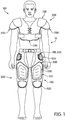
- an individual 10 is depicted as wearing an apparel system 100 that includes an exemplary upper protective garment 200 and a lower protective garment 300.
- Upper protective garment 200 has the general configuration of a shirt-type garment having shoulder pads, which may be utilized in various contact sports, such as American football.
- Upper protective garment 200 includes a plate component 210, a torso cushioning component 220, and a pair of shoulder cushioning components 230.
- Plate component 210 covers or extends over an upper torso and shoulders of individual 10.
- Torso cushioning component 220 is secured to plate component 210 and located between plate component 210 and individual 10.
- torso cushioning component 220 covers or extends over the upper torso and a middle torso of individual 10, thereby extending downward from plate component 210.
- Plate component 210, torso cushioning component 220, and shoulder cushioning components 230 impart padding, cushioning, or otherwise attenuate impact forces, thereby imparting protection to individual 10.
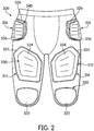
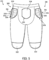
- An exemplary lower protective garment 300 of apparel system 100 exhibits the general configuration of a pants-type garment, which can include any of a plurality of articles of apparel that cover at least a portion of a pelvic area of individual 10 and may extend over the legs and cover the knees of individual 10.
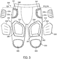
- Lower protective garment 300 incorporates cushioning components 320 and protective elements 310 which may include plate components 330 in addition to cushioning components 320.
- Cushioning components 320 can be positioned on the front, back, or sides of the knee, thigh, hip, and pelvic areas of lower protective garment 300.
- Plate components 330 may by incorporated with the cushioning components 320 to form protective elements 310 in any desirable area of lower protective garment 300.
- plate components 330 are shown secured to cushioning components 320 in the thigh and hip areas of lower protective garment 300.
- Cushioning components 320 of protective elements 310 are located between plate components 330 and individual 10.
- cushioning components 320, protective elements 310, and plate components 330 impart padding, cushioning, or otherwise attenuate impact forces, thereby imparting protection to individual 10.
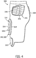
- cushioning components 320 are provided in the knee area and back pelvic area, referred to hereinafter as knee cushioning components 322 and rear cushioning component 328, respectively, to impart protection to the corresponding areas of individual 10.
- Protective elements 310 in the hip area include hip cushioning components 326 and hip plate components 336 that cooperatively impart protection to the corresponding hip areas of individual 10.
- Protective elements 310 in the thigh area herein after referred to as thigh protective elements 314, include thigh cushioning components 324 and thigh plate components 334 that cooperatively impart protection to the corresponding thigh areas of individual 10.
- cushioning components 320, plate components 330 or protective elements 310 may be positioned in various areas individually or in combination, including the sides or back of the leg regions or in the front or back of the pelvic region, to protect specific portions (e.g., muscles, bones, joints, impact areas) of individual 10.
- plate components 330 have an overall curved configuration that generally conforms to a shape of individual 10.
- plate components 330 may be depicted as generally planar in the drawings for simplicity.
- the quantity, shapes, sizes, and other properties of cushioning components 320 and plate components 330, as well as the materials utilized in cushioning components 320 and plate components 330 may vary significantly to provide a particular level of protection to the specific portions of individual 10.
- lower protective garment 300 is depicted as being short pants, various concepts disclosed below may also be applied to other pants-type garments, including pants, briefs, jeans, and underwear.
- the various concepts disclosed below for lower protective garment 300 may also be applied to upper protective garment 200 and other shirt-type garments, which cover a portion of a torso area of individual 10 and may extend over arms of individual 10.
- shirt-type garments include long-sleeved shirts, short-sleeved shirts, tank tops, undershirts, jackets, and coats.
- articles of apparel incorporating concepts disclosed below for garment 300 may be combinations of shirt-type garments and pants-type garments, including bodysuits, leotards, unitards, and wetsuits.
- articles of apparel incorporating concepts disclosed below for garment 300 may have configurations that cover other areas of individual 10, such as hats, helmets, arm and leg wraps, gloves, socks, and footwear, for example.
- lower protective garment 300 may be worn alone or exposed, lower protective garment 300 may also be worn in combination with other articles of apparel (e.g., under or over other articles of apparel). Apparel system 100 may also be worn in combination with other pieces of equipment (e.g., athletic or protective equipment). In general, lower protective garment 300 is worn over any inner garments, thereby positioning lower protective garment 300 to be the exterior garment worn by individual 10.
- cushioning components 320 may be constructed with a pad of polymer foam materials of cushioning components 320. When incorporated into apparel system 100 and protective garment 300, the pad of polymer foam materials of cushioning components 320 may compress to protect a wearer from contact with other athletes, equipment, or the ground.
- plate components 330 may be formed with semi-rigid or rigid polymer material to attenuate impact forces to provide protection. Plate components 330 may be configured to deform to absorb and distribute impact forces. Accordingly, protective elements 310 incorporating cushioning components 320 and plate components 330 may be utilized to provide protection to areas of individual 10 that are covered by protective elements 310. To explain in further detail, an example is provided below.
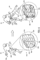
- FIG. 6 and FIGS. 7A through 7C provide an illustration of a collision scenario of a first player 20 with a second player 30.
- First player 20 is shown wearing an embodiment of apparel system 100, and in particular, wearing an embodiment of lower protective garment 300.
- player 20 is carrying a game ball and running downfield, for example, toward a scoring zone.
- An exemplary protective element 310 for a hip area of lower protective garment 300 is shown in detail in FIG. 6 , and in FIGS. 7A and 7B .
- hip protective element 316 includes hip cushioning component 326 and hip plate component 336.
- the hip cushioning component 326 is shown having a generally uniform thickness as can be seen at a peripheral edge 322 of hip cushioning component 326.
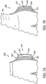
- FIG. 6 and FIGS. 7A through 7C (not to scale) provide an illustration of a collision scenario of a first player 20 with a second player 30.
- First player 20 is shown wearing an embodiment of apparel system 100, and in particular, wearing an embodiment of lower protective garment 300.
- lower protective garment is shown before being worn by first player 20.
- a space 337 may be provided between an interior of hip plate component 336 and an exterior of hip cushioning component 326.
- FIG. 7B lower protective garment is shown while being worn by first player 20.
- space 337 may become partially filled with a portion of hip cushioning component 326, due to the body of first player 20 pressing against the hip cushioning component 326, and due to the compressibility and flexibility of the material of hip cushioning component 326.
- hip plate component 336 In the first position of first player 20, hip plate component 336 is shown in an initial state, with virtually no forces being imparted to hip cushioning component 326 and hip plate component 336, other than from first player 20.
- the initial state of hip plate component 336 is shown having a generally convex curvature which extends outward from the exterior surface of hip cushioning component 326 with space 337 disposed there between.
- second player 30 is attempting to stop or tackle first player 20, for example.
- First player 20 is shown being hit in the hip area by the shoulder of second player 30.
- the second position of exemplary protective element 310 from hip area of lower protective garment 300 is shown in having an impact force from second player 30, as indicated by an arrow in FIG. 6 and FIG. 7C .
- the hip cushioning component 326 no longer has a uniform thickness but instead is compressed as depicted at the peripheral edge 322 of hip cushioning component 326.
- Hip plate component 336 is shown in a force attenuating state, in which the impact force is being absorbed and distributed, as the illustrated by zigzag lines.
- hip plate component 336 The force attenuating state of hip plate component 336 is further illustrated by the deformed hip plate component 336 having an indented curvature.
- hip plate component 336 pushes inward toward the exterior surface of hip cushioning component 326, thereby compressing hip cushioning component 326.
- Space 337 may be filled during the deformation of hip plate component 336 and compression of hip cushioning component 326, as shown in FIG. 7C .
- a plurality of flex indentations 338 may be provided on the exterior of hip plate component 336. Flex indentations 338 are configured to enhance flexibility and enable deformation of hip plate component 336 when exposed to an impact force.
- the impact force may be absorbed by deformation of the hip plate component 336 along flex indentations 338 into a partially concave shape as shown, for example.
- More or fewer flex indentations 338 may be provided in exemplary hip plate component 336 or for plate components 310 configured for other areas of individual 10.
- seams 328 in the exterior surface of hip cushioning component 326, which are configured to enhance flexibility in those area of the hip cushioning component 326 in which seam 328 are disposed.
- areas of cushioning components without seams 328 are stiffer than areas with seams 328.
- Seams 328 may be formed by a router for example, which can remove a portion of the exterior surface of hip cushioning component 326.
- the exterior surface of hip cushioning component 326 and the underlying material, foam padding for example may have different colors. The color of pad becomes exposed in the areas where first material layer was removed by a router. Here the exposed pad creates an aesthetically pleasing exterior of protective element 310.
- seams may be provided by other methods, such as stitching through the cushioning component or partially melting areas of the cushioning component, etc., to create seams 328.
- the collision scenario above describes one of many possible scenarios where protective elements 310 are used to protect an individual wearing a lower protective garment incorporating protective elements 310.
- the protective element remains intact during and after the collision.
- the protective elements incorporate a hook-and-loop type attachment system for attaching the plate component to the cushioning component.
- the plate component may become loosened or detached from the cushioning component, which is undesirable because of possible injury to the player or loss or destruction of the plate component.
- a more reliable permanent attachment method is provided which is utilized to prevent such an occurrence.
- the plate component may be securely stitched to the cushioning components.
- Such permanent attachment methods may be used as an alternative to or in combination with hook-and-loop type or other attachment systems.
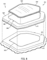
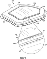
- FIGS. 8 through 12 illustrate various views of an exemplary embodiment for a protective element 310.
- thigh protective element 314 can include thigh cushioning component 324 and thigh plate component 334.
- Thigh cushioning component 324 includes a first material layer 311, a second material layer 312, at least one pad 313, and thigh plate component 334.
- pad 313 is positioned between first material layer 311 and second material layer 312.
- First material layer 311 and second material layer 312 cooperatively form an outer surface or covering for thigh cushioning components 324. That is, first material layer 311 and second material layer 312 cooperatively form a pocket or void, in which pad 313 is located.
- first material layer 311 extends over pad 313 and also along sides of pad 313 to join with second material layer 312 (e.g., through stitching, an adhesive, or thermal bonding, not shown).
- first material layer 311 may be positioned exterior of second material layer 312. That is, first material layer 311 may form a portion of an exterior surface of lower protective garment 300.
- An advantage to this configuration is that thigh cushioning component 324 protrudes outward from lower protective garment 300, rather than protruding inward and toward individual 10. In some configurations of protective garment 300, however, other cushioning components 320 may protrude inward.
- thigh plate component 334 is located at an exterior of thigh cushioning component 324 (i.e., located exterior of first material layer 311).
- cushioning components 320 in the hip areas and thigh areas are incorporated with plate components 330.
- further plates are absent from other cushioning components 320, such as in the knee and back pelvic areas.
- additional plate components 330 may be utilized in other cushioning components 320.
- first material layer 311 and second material layer 312 A variety of materials may be utilized for first material layer 311 and second material layer 312, including various textiles, polymer sheets, leather, or synthetic leather, for example. Combinations of these materials (e.g., a polymer sheet bonded to a textile) may also be utilized for first material layer 311 and second material layer 312.
- first material layer 311 and second material layer 312 may be formed from the same material, each of first material layer 311 and second material layer 312 may also be formed from different materials.
- first material layer 311 and second material layer 312 may be formed from knitted, woven, or non-woven textile elements that include rayon, nylon, polyester, polyacrylic, cotton, wool, or silk, for example.
- the textiles may be nonstretch, may exhibit one-directional stretch, or may exhibit multi-directional stretch. Accordingly, a variety of materials are suitable for first material layer 311 and second material layer 312.
- thigh cushioning component 324 may include a plurality of pads to configure a cushioning component with particular parameters, in accordance for the particular area of the body which the cushioning component is being applied.
- the thickness of pad 313 may vary depending upon various factors, including the type of material utilized for pad 313 and the desired level of protection. In general, however, the thickness of pad 313 may range from one to fifty millimeters or more when formed from a polymer foam material. Although pad 313 may exhibit a constant thickness between first material layer 311 and second material layer 312, the thickness may vary across the width of pad 313. For example, edges of pad 313 may be thinner than central areas of pad 313. Various apertures, gaps, and indentations may also be formed in pad 313 to enhance flexibility and breathability.
- Pad 313 may also be formed from a variety of materials, including various polymer foam materials that return to an original shape after being compressed. As an alternative to polymer foam materials, pad 313 may also be formed as fluid-filled chambers. Examples of suitable polymer foam materials for pad 313 include polyurethane, ethylvinylacetate, polyester, polypropylene, and polyethylene foams. Moreover, both thermoplastic and thermoset polymer foam materials may be utilized. In some configurations of cushioning components 320, pad 313 may be formed from a polymer foam material with a varying density, or solid polymer or rubber materials may be utilized. Also, different pad 313 may be formed from different materials, or may be formed from similar materials with different densities.
- Plate components 330 have an overall curved configuration that generally conforms to the shape of individual 10. Given that protective components 310 may be utilized to protect a thigh or hip of individual 10, plate components 330 may exhibit a curvature that corresponds with the thigh or hip, respectively. Additionally, plate components 330 may include various ribs (shown schematically) that enhance rigidity. In further configurations, plate components 330 may have a variety of other features that enhance the comfort or protective properties of apparel system 100 or protective component 310. For example, plate components 330 may define a plurality of apertures that enhance breathability or flexibility, plate components 330 may be formed from multiple materials that vary the rigidity or flexibility in different areas, or plate components 330 may have a varying thickness that also vary the rigidity or flexibility in different areas.
- Plate components 330 are primarily formed from a semi-rigid or rigid polymer material, which may be a non-foamed polymer material.
- suitable polymer materials for plate components 330 include polyethylene, polyurethane, polypropylene, acrylonitrile butadiene styrene, polyester, thermoset urethane, thermoplastic urethane, polyether block amide, polybutylene terephthalate various nylon formulations, or blends of these materials.
- Composite materials may also be formed by incorporating glass fibers, aramid fibers, or carbon fibers, for example, into the polymer materials discussed above in order to enhance the strength and rigidity of plate components 330.
- plate components 330 may also be formed from metal materials (e.g., aluminum, titanium, steel) or may include metal elements that enhance the strength and rigidity of plate components 330. Accordingly, a variety of materials may be utilized for plate components 330.
- Protective elements 310 which include plate components 330 and cushioning components 320, may be assembled before or after attachment of the protective elements 310 to lower protective garment 300, for example.
- the assembly of protective elements is typically performed by humans, rather than by automated machines or robots.
- One reason for this is that the positioning and attachment of the plate component relative to be cushioning components, and of the cushioning component to the garment, are tasks which are not easily automated.
- a human eye and touch is preferable in such types of tasks, particularly since the plate and/or cushioning component may have an irregular shape and/or curvature which requires careful positioning and guiding through a sewing machine or stapling machine.
- a method for assembly of protective elements incudes steps for facilitating a human when attaching a plate component to a cushioning component. Such methods are useful when a human needs to position and attach the plate component to the cushioning component, for example by using a hand held sewing machine, to ensure accuracy in the placement of the plate component, but do not form part of the claimed invention.
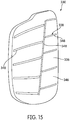
- thigh cushioning components 324 and hip cushioning components 326 of protective elements 310 are provided with a guide pattern 340 disposed on the exterior surfaces thereof.
- Guide pattern 340 are configured in or on the thigh cushioning components 324 and hip cushioning components 326 to provide a visual guide to a person assembling the protective elements 310 of lower protective garment 300. More particularly, guide pattern 340 forms a visual guide for attaching thigh plate components 334 and hip plate components 336 to respective thigh cushioning components 324 and hip cushioning components 326 of protective elements 310.
- a portion 341 of the first material layer 311 may be removed by a router, for example (not shown), or another cutting tool which thereby forms guide pattern 340 on the exterior of thigh cushioning component 324 (also see FIG. 8 ).
- This cutting creates a depression, groove, or incision in thigh cushioning component 324.
- the depression may have a bottom, which may be flat or curved, and sidewalls, which may be flat or curved. The sidewalls extend from the bottom to the exterior surface of the first material layer.
- the bottom of the depression may be between the exterior surface of first material layer 311 and an interior surface of first material layer 311.
- the bottom of the depression in some embodiments may be within the cushioning components.
- the depression extends entirely through first material layer 311 and into the cushioning components. In some embodiments, sufficient material is removed so that the sidewalls are spaced apart from each other. In other embodiments, the sidewalls may touch in one or more positions along the depression or incisions.
- the first material layer 311 and the pad 313 may be different colors, such that the color of the pad is exposed through portion 341 of the first material layer that has been removed. For example, if the first material layer 311 is black and the pad 313 is red, the guide pattern appears because the red pad 313 is exposed at portion 341 of first material layer 311, and the contrasting colors make the guide pattern visible. Additionally, a portion 343 of the pad 313 may also be removed by routing, for example, at the same time or at a different time as the portion 341 of first material later 311, thereby forming an indentation in at least a top surface of pad 313 at portion 343.
- the guide pattern be useful for positioning a plate component on an appropriate portion of a cushioning component, but additionally, the indentation in portion 343 of pad 313 can be utilized to position a plate component relative to the pad and facilitate attachment of plate to the pad, as will be explained in detail below, with reference to FIG 14 .
- guide pattern 340 may be formed by stitching through first material layer 311 to form a pattern of stiches left in first material layer (represented schematically). Additionally, guide pattern 340 may be formed by stitching through first material layer 311 and at least a portion of pad 313 to form an indentation in thigh cushioning component 324 at portion 341.
- first material layer 311 may be formed by stitching through first material layer 311 and at least a portion of pad 313 to form an indentation in thigh cushioning component 324 at portion 341.
- the guide patterns may be configured to have a substantially equal or a smaller area than the plate components, so as to be hidden or covered when the plate component is attached to the cushioning component. Additionally, in some embodiments at least a portion of or all of the guide pattern may be configured to have a larger area than the plate components, so as to be at least partially visible or exposed when the plate component is attached to the cushioning component. Furthermore, the configuration of the guide pattern can vary in a thickness and a depth for example, which parameters may correspond to the shape of a particular plate component.
- the thigh plate component 334 of lower protective garment 300 can be provided with an attachment area 350 extending along a peripheral edge or perimeter thereof.
- Attachment area 350 can be configured to provide a reduced thickness portion of thigh plate component 334 at an area desirable to attach the plate component to the cushioning component.
- attachment area 350 may extend around the entire outer perimeter of the plate component, thereby encompassing the plate component.
- Attachment area 350 is formed in the thigh plate component 334 to allow for attachment of thigh plate component 334 to thigh cushioning component 324 at attachment area 350.
- attachment area 350 extends around the entire perimeter of thigh plate component 344, the stitching or stapling provided in the attachment area also encompasses thigh plate component 334, thereby ensuring a secure attachment.
- attachment area 350 is shown in the perimeter of thigh plate component 334, alternative areas for providing an attachment area are possible. For example some attachment areas could be provided on alternating edges around the perimeter of a plate component, or in the middle of a plate component, or a combination thereof.
- thigh plate component 334 has attachment area 350 provided near the peripheral edge or perimeter of the thigh plate component 334.
- Attachment area 350 may be configured as a groove or channel, which can be formed during manufacturing of the plate component, such as by a mold during injection molding. Alternatively, attachment area 350 could be formed by being routed into the plate component after manufacturing of the plate component, for example.
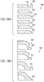
- FIGS. 13A and 13B show cross-sectional views of generally flat-edged plate components and generally curved-edged plate components, respectively.
- attachment area 350 may be configured as a groove or channel, having a semicircular profile 351.
- attachment areas 350 can be configured as a channel having a partially semicircular profile 352 or a curved profile 353 cut into a top and outer edge of a plate component.
- attachment area 350 may be configured as an "L" shaped notch 354, a slanted edge 355, or as a beveled edge 356.
- thigh plate component 334 is attached to thigh cushioning component 324 by stitches or staples of attachment medium 360 provided in attachment area 350 of plate.
- the thigh plate component 334 may have a thickness of 3.5 millimeters, for example.
- attachment area 350 formed in the thigh plate component 334 can have a reduced thickness of 1.5 millimeters, for example.
- an attachment device 362 such as a needle from a hand-held sewing machine, for example (shown schematically for simplicity), to penetrate more easily through the plate material, while maintaining the strength of thigh plate component 334 in attachment area 350.
- stitches of attachment medium 360 are made in attachment area 350 of the plate at a rate of 4 to 6 stitches per inch (2.54 cm). More or less stiches may be provided depending on the thicknesses of the plate component and of attachment medium 360.
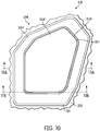
- FIGS. 10 through 12 an example for assembling protective component 310 is shown using a guide pattern and attachment area 350, described above.
- FIG 10 shows a plan view of thigh protective element 314 having thigh plate component 334 positioned on thigh cushioning component 324.
- plate component 334 can be positioned on the appropriate area of thigh cushioning component 324 using guide pattern 340 ( FIG 8 ), in a manner so as to conceal guide pattern 340, which may be desirable in some embodiments.
- thigh plate component 334 is provided with attachment area 350 which can be formed as a groove, for example.
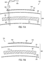
- FIG. 11A demonstrates a simplified example of a stitching path (shown as a dotted line) for a needle 362 and stitching medium 360 to pass through thigh plate component 334 at attachment area 350.
- the stitching path continues then through first material layer 311, top surface 321 of pad 313, bottom surface 322 of pad 313, second material layer 312, and then back through to bottom surface 322 of pad 313, top surface 321 of pad 313, first material layer 311 and thigh plate component 334.
- FIGS. 11A and 11B represent the exploded cross-sectional views of FIG. 10 prior to a step of stitching
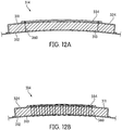
- FIGS. 12A and 12B represent cross-sectional views of FIG. 10 after a step of stitching.
- this configuration of attachment area 350 is discussed with respect to plate components 330 in the thigh area, the concept may also be applied to plate components 330 in other areas of individual 10, as will be explained below with reference FIG. 14 .
- the pad component may omit the second material layer 312, and only include first material layer and pad 313.
- the plate component may be attached to the pad by the stitching method described above, however by stitching only through the plate component, the first material layer, to the bottom of pad, and then back through the first material and plate component. This may be desirable when the plate component is attached to the cushioning component prior to the cushioning component being attached to a garment such as lower protective garment 300.
- FIG. 14 shows a detailed cross-sectional view of an embodiment for attachment of plate component 330 to cushioning component 320.
- plate component 330 of protective element 310 has a more curved configuration than thigh plate component 334 discussed above.
- Such a curved configuration of plate component 330 may be used in a protective element for the hip area, for example.
- Plate component 330 can be provided with an attachment area 350 disposed in the peripheral edge or perimeter thereof. Attachment area 350 can be configured to provide a reduced thickness portion of plate component 330 at an area desirable to attach plate component 330 to cushioning component 320.
- cushioning component 320 is provided with an opening at portion 341 of first material 311 and a coinciding indentation in portion 343 of pad 313, which are configured to receive the attachment area 350 of plate component 330.
- the opening at portion 341 of first material layer 311 is used as a visual guide to accurately position plate component 330 on cushioning component for attachment. It is advantageous to have the exterior of cushioning component 320 flush with the interior of plate component 330 at attachment area 350 to facilitate stitching through plate component 330 to cushioning component 320. Accordingly, attachment area 350 of plate component 330 is shown having first material later 311 and pad 313 disposed adjacently to the interior side of plate component 330.
- Plate component 330 is configured as a hip plate component 336 having a plurality of flex indentions 338, which were described previously with reference to FIG 6 .
- Flex indentations 338 are configured to enhance flexibility and enable deformation of hip plate component 336 when exposed to an impact force. Flex indentations 338 may be provided on the exterior of hip plate component 336 and may be configured as grooves or channels, which can be formed during manufacturing of the plate component, such as by a mold during injection molding. Alternatively, flex indentations 338 could be formed by being routed into the plate component after manufacturing of the plate component, for example.
- flex indentation are formed within a first material 346 of plate component 330.
- a second material 348 can be disposed in the flex indentations 338, thereby filling in the flex indentations 338. Additionally, the second material 348 can have a greater flexibility and compressibility than first material 346, so as to provide cushioning and force attenuation at the flex indentation during deformation of the plate component 330. Second material 348 can be deposited onto first material 346 by co-molding for example. However, other methods of manufacturing are possible.
- flex indentations 338 provided in a plate component are discussed with respect to a hip plate component, the concepts may also be applied to plate components in other areas of a protective garment incorporating protective elements, such as thigh plate components 334, which show representative flex indentations in several of the figures, although not enumerated.
Landscapes
- Health & Medical Sciences (AREA)
- General Health & Medical Sciences (AREA)
- Physical Education & Sports Medicine (AREA)
- Engineering & Computer Science (AREA)
- Textile Engineering (AREA)
- Professional, Industrial, Or Sporting Protective Garments (AREA)
- Buffer Packaging (AREA)
Claims (9)
- Schutzelement (310) für ein Bekleidungsstück, umfassend:eine Plattenkomponente (330), die eine Umfangsform aufweist;eine erste Materialschicht (311), die eine Außenoberfläche und eine gegenüberliegende Innenoberfläche aufweist, wobei die Außenoberfläche angrenzend an die Plattenkomponente positioniert ist;eine Polsterkomponente (313), die eine erste Oberfläche aufweist, die angrenzend an ein Inneres der ersten Materialschicht positioniert ist;ein Führungsmuster (340) auf der Außenoberfläche der ersten Materialschicht, gegenüber dem Inneren, angrenzend an die Polsterkomponente, worin das Führungsmuster der Umfangsform der Plattenkomponente entspricht,wobei die Plattenkomponente auf der ersten Materialschicht unter Verwendung des Führungsmusters positioniert ist; undein Befestigungselement, welches die Plattenkomponente an die erste Materialschicht in der Nähe des Führungsmusters befestigt, wobei das Befestigungselement eine Befestigung vom Klettverschlusstyp ist.
- Schutzelement nach Anspruch 1, wobei die Plattenkomponente eine höhere Steifigkeit als die Polsterkomponente aufweist.
- Schutzelement nach Anspruch 1, wobei das Führungsmuster ein sich vollständig durch die erste Materialschicht erstreckender Einschnitt ist, der die Polsterkomponente freilegt.
- Schutzelement nach einem der Ansprüche 1 bis 3, wobei die Polsterkomponente eine erste Farbe aufweist und die Plattenkomponente eine zweite Farbe aufweist, wobei die erste Farbe von der zweiten Farbe verschieden ist.
- Schutzelement nach Anspruch 1, wobei das Führungsmuster eine Vertiefung in der ersten Materialschicht ist,
wobei die Vertiefung einen Boden und Seitenwände einschließt,
wobei der Boden zwischen der Außenoberfläche der ersten Materialschicht und der Innenoberfläche der ersten Materialschicht angeordnet ist, und
wobei die Seitenwände sich von dem Boden zu der Außenoberfläche der ersten Materialschicht erstrecken. - Schutzelement nach Anspruch 1, wobei sich das Führungsmuster in die Polsterkomponente erstreckt.
- Schutzelement nach einem der Ansprüche 1 bis 6, wobei die Plattenkomponente ein energieabführendes Element ist und die Polsterkomponente ein dämpfendens Element ist.
- Schutzelement nach einem der Ansprüche 1 bis 7, wobei das Schutzelement an der äußersten Schicht eines Bekleidungsstückes befestigt ist.
- Schutzelement nach einem der Ansprüche 1 bis 8, wobei die Plattenkomponente zusätzlich an die erste Materialschicht durch Nähen befestigt ist.
Applications Claiming Priority (3)
| Application Number | Priority Date | Filing Date | Title |
|---|---|---|---|
| US13/927,436 US9149084B2 (en) | 2009-06-23 | 2013-06-26 | Apparel incorporating a protective element and method for making |
| PCT/US2014/044387 WO2014210343A2 (en) | 2013-06-26 | 2014-06-26 | Apparel incorporating a protective element and method for making |
| EP14752449.0A EP3013167B1 (de) | 2013-06-26 | 2014-06-26 | Kleidungsstück mit einem schutzelement und verfahren zur herstellung |
Related Parent Applications (1)
| Application Number | Title | Priority Date | Filing Date |
|---|---|---|---|
| EP14752449.0A Division EP3013167B1 (de) | 2013-06-26 | 2014-06-26 | Kleidungsstück mit einem schutzelement und verfahren zur herstellung |
Publications (2)
| Publication Number | Publication Date |
|---|---|
| EP3378342A1 EP3378342A1 (de) | 2018-09-26 |
| EP3378342B1 true EP3378342B1 (de) | 2020-02-12 |
Family
ID=51355607
Family Applications (2)
| Application Number | Title | Priority Date | Filing Date |
|---|---|---|---|
| EP18172477.4A Active EP3378342B1 (de) | 2013-06-26 | 2014-06-26 | Schutzelement für einem kleidungsstück |
| EP14752449.0A Active EP3013167B1 (de) | 2013-06-26 | 2014-06-26 | Kleidungsstück mit einem schutzelement und verfahren zur herstellung |
Family Applications After (1)
| Application Number | Title | Priority Date | Filing Date |
|---|---|---|---|
| EP14752449.0A Active EP3013167B1 (de) | 2013-06-26 | 2014-06-26 | Kleidungsstück mit einem schutzelement und verfahren zur herstellung |
Country Status (3)
| Country | Link |
|---|---|
| EP (2) | EP3378342B1 (de) |
| CN (1) | CN105491901B (de) |
| WO (1) | WO2014210343A2 (de) |
Family Cites Families (12)
| Publication number | Priority date | Publication date | Assignee | Title |
|---|---|---|---|---|
| US4512037A (en) * | 1982-08-17 | 1985-04-23 | Sports Marketing, Inc. | Protective pad assembly |
| US4441211A (en) * | 1983-03-25 | 1984-04-10 | Houston Protective Equipment, Inc. | Protective batting jacket |
| US4525875A (en) * | 1983-07-15 | 1985-07-02 | Macgregor Sporting Goods, Inc. | Chest protector with rigid plates |
| ATE48370T1 (de) * | 1986-07-25 | 1989-12-15 | Descente Ltd | Schutzteil fuer einen sportanzug. |
| US5337418A (en) * | 1988-07-08 | 1994-08-16 | K & K Inc. | Protector and article of sportswear using the same |
| US5373584A (en) * | 1993-02-19 | 1994-12-20 | Parcells, Iii; Charles A. | Sliding accessories to permit in-line roller skating maneuvers equivalent to ice skating maneuvers |
| US6105162A (en) * | 1996-09-03 | 2000-08-22 | Douglas Protective Equipment, Inc. | Hand protector |
| DE29619260U1 (de) * | 1996-11-06 | 1997-02-20 | Leberkern, Lenz, 92681 Erbendorf | Protektoren-Schutzanzug für den Kartsport |
| JP2000314074A (ja) * | 1998-03-31 | 2000-11-14 | Kiyoshi Mishima | 生地への模様形成方法及びそれに用いられるミシン並びに針通過孔群形成装置 |
| US7219372B2 (en) * | 2004-05-20 | 2007-05-22 | Craig Frieler | Kneepad |
| US8095996B2 (en) * | 2009-06-23 | 2012-01-17 | Nike, Inc. | Apparel incorporating a protective element |
| US8438669B2 (en) * | 2009-06-23 | 2013-05-14 | Nike, Inc. | Apparel incorporating a protective element |
-
2014
- 2014-06-26 CN CN201480047266.XA patent/CN105491901B/zh active Active
- 2014-06-26 WO PCT/US2014/044387 patent/WO2014210343A2/en not_active Ceased
- 2014-06-26 EP EP18172477.4A patent/EP3378342B1/de active Active
- 2014-06-26 EP EP14752449.0A patent/EP3013167B1/de active Active
Non-Patent Citations (1)
| Title |
|---|
| None * |
Also Published As
| Publication number | Publication date |
|---|---|
| WO2014210343A2 (en) | 2014-12-31 |
| CN105491901B (zh) | 2018-02-06 |
| EP3013167B1 (de) | 2018-05-30 |
| EP3013167A2 (de) | 2016-05-04 |
| CN105491901A (zh) | 2016-04-13 |
| WO2014210343A3 (en) | 2015-03-05 |
| EP3378342A1 (de) | 2018-09-26 |
Similar Documents
| Publication | Publication Date | Title |
|---|---|---|
| US9149084B2 (en) | Apparel incorporating a protective element and method for making | |
| EP2445364B1 (de) | Kleidung mit einem schutzelement | |
| US8438669B2 (en) | Apparel incorporating a protective element | |
| EP2555914B1 (de) | Herstellungsverfahren von polsterungselementen für bekleidung und andere produkte | |
| US10034498B2 (en) | Articles of apparel incorporating cushioning elements | |
| EP2678150B1 (de) | Polsterungselemente für bekleidung und andere produkte sowie verfahren zur herstellung der polsterungselemente | |
| US10194707B2 (en) | Apparel incorporating a protective element | |
| EP2709478B1 (de) | Verfahren zur herstellung von polsterungselementen für bekleidung und andere produkte | |
| EP2480104B1 (de) | Kleidungsstück mit einem schutzelement | |
| EP2736364B1 (de) | Bekleidungsartikel mit dämpfungselementen | |
| US20130025036A1 (en) | Articles Of Apparel Incorporating Cushioning Elements | |
| EP2858727B1 (de) | Bekleidungsartikel mit dämpfungselementen | |
| CN104379008B (zh) | 包含缓冲元件的服装物品 | |
| EP3013167B1 (de) | Kleidungsstück mit einem schutzelement und verfahren zur herstellung |
Legal Events
| Date | Code | Title | Description |
|---|---|---|---|
| PUAI | Public reference made under article 153(3) epc to a published international application that has entered the european phase |
Free format text: ORIGINAL CODE: 0009012 |
|
| STAA | Information on the status of an ep patent application or granted ep patent |
Free format text: STATUS: THE APPLICATION HAS BEEN PUBLISHED |
|
| AC | Divisional application: reference to earlier application |
Ref document number: 3013167 Country of ref document: EP Kind code of ref document: P |
|
| AK | Designated contracting states |
Kind code of ref document: A1 Designated state(s): AL AT BE BG CH CY CZ DE DK EE ES FI FR GB GR HR HU IE IS IT LI LT LU LV MC MK MT NL NO PL PT RO RS SE SI SK SM TR |
|
| STAA | Information on the status of an ep patent application or granted ep patent |
Free format text: STATUS: REQUEST FOR EXAMINATION WAS MADE |
|
| 17P | Request for examination filed |
Effective date: 20190322 |
|
| RBV | Designated contracting states (corrected) |
Designated state(s): AL AT BE BG CH CY CZ DE DK EE ES FI FR GB GR HR HU IE IS IT LI LT LU LV MC MK MT NL NO PL PT RO RS SE SI SK SM TR |
|
| GRAP | Despatch of communication of intention to grant a patent |
Free format text: ORIGINAL CODE: EPIDOSNIGR1 |
|
| STAA | Information on the status of an ep patent application or granted ep patent |
Free format text: STATUS: GRANT OF PATENT IS INTENDED |
|
| INTG | Intention to grant announced |
Effective date: 20190916 |
|
| GRAS | Grant fee paid |
Free format text: ORIGINAL CODE: EPIDOSNIGR3 |
|
| GRAA | (expected) grant |
Free format text: ORIGINAL CODE: 0009210 |
|
| STAA | Information on the status of an ep patent application or granted ep patent |
Free format text: STATUS: THE PATENT HAS BEEN GRANTED |
|
| AC | Divisional application: reference to earlier application |
Ref document number: 3013167 Country of ref document: EP Kind code of ref document: P |
|
| AK | Designated contracting states |
Kind code of ref document: B1 Designated state(s): AL AT BE BG CH CY CZ DE DK EE ES FI FR GB GR HR HU IE IS IT LI LT LU LV MC MK MT NL NO PL PT RO RS SE SI SK SM TR |
|
| REG | Reference to a national code |
Ref country code: GB Ref legal event code: FG4D |
|
| REG | Reference to a national code |
Ref country code: CH Ref legal event code: EP |
|
| REG | Reference to a national code |
Ref country code: AT Ref legal event code: REF Ref document number: 1230929 Country of ref document: AT Kind code of ref document: T Effective date: 20200215 |
|
| REG | Reference to a national code |
Ref country code: IE Ref legal event code: FG4D |
|
| REG | Reference to a national code |
Ref country code: DE Ref legal event code: R096 Ref document number: 602014061117 Country of ref document: DE |
|
| PG25 | Lapsed in a contracting state [announced via postgrant information from national office to epo] |
Ref country code: RS Free format text: LAPSE BECAUSE OF FAILURE TO SUBMIT A TRANSLATION OF THE DESCRIPTION OR TO PAY THE FEE WITHIN THE PRESCRIBED TIME-LIMIT Effective date: 20200212 Ref country code: FI Free format text: LAPSE BECAUSE OF FAILURE TO SUBMIT A TRANSLATION OF THE DESCRIPTION OR TO PAY THE FEE WITHIN THE PRESCRIBED TIME-LIMIT Effective date: 20200212 Ref country code: NO Free format text: LAPSE BECAUSE OF FAILURE TO SUBMIT A TRANSLATION OF THE DESCRIPTION OR TO PAY THE FEE WITHIN THE PRESCRIBED TIME-LIMIT Effective date: 20200512 |
|
| REG | Reference to a national code |
Ref country code: LT Ref legal event code: MG4D |
|
| REG | Reference to a national code |
Ref country code: NL Ref legal event code: MP Effective date: 20200212 |
|
| PG25 | Lapsed in a contracting state [announced via postgrant information from national office to epo] |
Ref country code: IS Free format text: LAPSE BECAUSE OF FAILURE TO SUBMIT A TRANSLATION OF THE DESCRIPTION OR TO PAY THE FEE WITHIN THE PRESCRIBED TIME-LIMIT Effective date: 20200612 Ref country code: BG Free format text: LAPSE BECAUSE OF FAILURE TO SUBMIT A TRANSLATION OF THE DESCRIPTION OR TO PAY THE FEE WITHIN THE PRESCRIBED TIME-LIMIT Effective date: 20200512 Ref country code: LV Free format text: LAPSE BECAUSE OF FAILURE TO SUBMIT A TRANSLATION OF THE DESCRIPTION OR TO PAY THE FEE WITHIN THE PRESCRIBED TIME-LIMIT Effective date: 20200212 Ref country code: SE Free format text: LAPSE BECAUSE OF FAILURE TO SUBMIT A TRANSLATION OF THE DESCRIPTION OR TO PAY THE FEE WITHIN THE PRESCRIBED TIME-LIMIT Effective date: 20200212 Ref country code: HR Free format text: LAPSE BECAUSE OF FAILURE TO SUBMIT A TRANSLATION OF THE DESCRIPTION OR TO PAY THE FEE WITHIN THE PRESCRIBED TIME-LIMIT Effective date: 20200212 Ref country code: GR Free format text: LAPSE BECAUSE OF FAILURE TO SUBMIT A TRANSLATION OF THE DESCRIPTION OR TO PAY THE FEE WITHIN THE PRESCRIBED TIME-LIMIT Effective date: 20200513 |
|
| PG25 | Lapsed in a contracting state [announced via postgrant information from national office to epo] |
Ref country code: NL Free format text: LAPSE BECAUSE OF FAILURE TO SUBMIT A TRANSLATION OF THE DESCRIPTION OR TO PAY THE FEE WITHIN THE PRESCRIBED TIME-LIMIT Effective date: 20200212 |
|
| PG25 | Lapsed in a contracting state [announced via postgrant information from national office to epo] |
Ref country code: DK Free format text: LAPSE BECAUSE OF FAILURE TO SUBMIT A TRANSLATION OF THE DESCRIPTION OR TO PAY THE FEE WITHIN THE PRESCRIBED TIME-LIMIT Effective date: 20200212 Ref country code: PT Free format text: LAPSE BECAUSE OF FAILURE TO SUBMIT A TRANSLATION OF THE DESCRIPTION OR TO PAY THE FEE WITHIN THE PRESCRIBED TIME-LIMIT Effective date: 20200705 Ref country code: LT Free format text: LAPSE BECAUSE OF FAILURE TO SUBMIT A TRANSLATION OF THE DESCRIPTION OR TO PAY THE FEE WITHIN THE PRESCRIBED TIME-LIMIT Effective date: 20200212 Ref country code: ES Free format text: LAPSE BECAUSE OF FAILURE TO SUBMIT A TRANSLATION OF THE DESCRIPTION OR TO PAY THE FEE WITHIN THE PRESCRIBED TIME-LIMIT Effective date: 20200212 Ref country code: SK Free format text: LAPSE BECAUSE OF FAILURE TO SUBMIT A TRANSLATION OF THE DESCRIPTION OR TO PAY THE FEE WITHIN THE PRESCRIBED TIME-LIMIT Effective date: 20200212 Ref country code: CZ Free format text: LAPSE BECAUSE OF FAILURE TO SUBMIT A TRANSLATION OF THE DESCRIPTION OR TO PAY THE FEE WITHIN THE PRESCRIBED TIME-LIMIT Effective date: 20200212 Ref country code: RO Free format text: LAPSE BECAUSE OF FAILURE TO SUBMIT A TRANSLATION OF THE DESCRIPTION OR TO PAY THE FEE WITHIN THE PRESCRIBED TIME-LIMIT Effective date: 20200212 Ref country code: SM Free format text: LAPSE BECAUSE OF FAILURE TO SUBMIT A TRANSLATION OF THE DESCRIPTION OR TO PAY THE FEE WITHIN THE PRESCRIBED TIME-LIMIT Effective date: 20200212 Ref country code: EE Free format text: LAPSE BECAUSE OF FAILURE TO SUBMIT A TRANSLATION OF THE DESCRIPTION OR TO PAY THE FEE WITHIN THE PRESCRIBED TIME-LIMIT Effective date: 20200212 |
|
| REG | Reference to a national code |
Ref country code: DE Ref legal event code: R097 Ref document number: 602014061117 Country of ref document: DE |
|
| REG | Reference to a national code |
Ref country code: AT Ref legal event code: MK05 Ref document number: 1230929 Country of ref document: AT Kind code of ref document: T Effective date: 20200212 |
|
| PLBE | No opposition filed within time limit |
Free format text: ORIGINAL CODE: 0009261 |
|
| STAA | Information on the status of an ep patent application or granted ep patent |
Free format text: STATUS: NO OPPOSITION FILED WITHIN TIME LIMIT |
|
| 26N | No opposition filed |
Effective date: 20201113 |
|
| PG25 | Lapsed in a contracting state [announced via postgrant information from national office to epo] |
Ref country code: IT Free format text: LAPSE BECAUSE OF FAILURE TO SUBMIT A TRANSLATION OF THE DESCRIPTION OR TO PAY THE FEE WITHIN THE PRESCRIBED TIME-LIMIT Effective date: 20200212 Ref country code: MC Free format text: LAPSE BECAUSE OF FAILURE TO SUBMIT A TRANSLATION OF THE DESCRIPTION OR TO PAY THE FEE WITHIN THE PRESCRIBED TIME-LIMIT Effective date: 20200212 Ref country code: AT Free format text: LAPSE BECAUSE OF FAILURE TO SUBMIT A TRANSLATION OF THE DESCRIPTION OR TO PAY THE FEE WITHIN THE PRESCRIBED TIME-LIMIT Effective date: 20200212 |
|
| REG | Reference to a national code |
Ref country code: CH Ref legal event code: PL |
|
| PG25 | Lapsed in a contracting state [announced via postgrant information from national office to epo] |
Ref country code: SI Free format text: LAPSE BECAUSE OF FAILURE TO SUBMIT A TRANSLATION OF THE DESCRIPTION OR TO PAY THE FEE WITHIN THE PRESCRIBED TIME-LIMIT Effective date: 20200212 Ref country code: PL Free format text: LAPSE BECAUSE OF FAILURE TO SUBMIT A TRANSLATION OF THE DESCRIPTION OR TO PAY THE FEE WITHIN THE PRESCRIBED TIME-LIMIT Effective date: 20200212 |
|
| PG25 | Lapsed in a contracting state [announced via postgrant information from national office to epo] |
Ref country code: LU Free format text: LAPSE BECAUSE OF NON-PAYMENT OF DUE FEES Effective date: 20200626 |
|
| REG | Reference to a national code |
Ref country code: BE Ref legal event code: MM Effective date: 20200630 |
|
| PG25 | Lapsed in a contracting state [announced via postgrant information from national office to epo] |
Ref country code: IE Free format text: LAPSE BECAUSE OF NON-PAYMENT OF DUE FEES Effective date: 20200626 Ref country code: LI Free format text: LAPSE BECAUSE OF NON-PAYMENT OF DUE FEES Effective date: 20200630 Ref country code: CH Free format text: LAPSE BECAUSE OF NON-PAYMENT OF DUE FEES Effective date: 20200630 |
|
| PG25 | Lapsed in a contracting state [announced via postgrant information from national office to epo] |
Ref country code: BE Free format text: LAPSE BECAUSE OF NON-PAYMENT OF DUE FEES Effective date: 20200630 |
|
| PG25 | Lapsed in a contracting state [announced via postgrant information from national office to epo] |
Ref country code: TR Free format text: LAPSE BECAUSE OF FAILURE TO SUBMIT A TRANSLATION OF THE DESCRIPTION OR TO PAY THE FEE WITHIN THE PRESCRIBED TIME-LIMIT Effective date: 20200212 Ref country code: MT Free format text: LAPSE BECAUSE OF FAILURE TO SUBMIT A TRANSLATION OF THE DESCRIPTION OR TO PAY THE FEE WITHIN THE PRESCRIBED TIME-LIMIT Effective date: 20200212 Ref country code: CY Free format text: LAPSE BECAUSE OF FAILURE TO SUBMIT A TRANSLATION OF THE DESCRIPTION OR TO PAY THE FEE WITHIN THE PRESCRIBED TIME-LIMIT Effective date: 20200212 |
|
| PG25 | Lapsed in a contracting state [announced via postgrant information from national office to epo] |
Ref country code: MK Free format text: LAPSE BECAUSE OF FAILURE TO SUBMIT A TRANSLATION OF THE DESCRIPTION OR TO PAY THE FEE WITHIN THE PRESCRIBED TIME-LIMIT Effective date: 20200212 Ref country code: AL Free format text: LAPSE BECAUSE OF FAILURE TO SUBMIT A TRANSLATION OF THE DESCRIPTION OR TO PAY THE FEE WITHIN THE PRESCRIBED TIME-LIMIT Effective date: 20200212 |
|
| P01 | Opt-out of the competence of the unified patent court (upc) registered |
Effective date: 20230515 |
|
| PGFP | Annual fee paid to national office [announced via postgrant information from national office to epo] |
Ref country code: GB Payment date: 20260409 Year of fee payment: 13 |
|
| PGFP | Annual fee paid to national office [announced via postgrant information from national office to epo] |
Ref country code: DE Payment date: 20260331 Year of fee payment: 13 |
|
| PGFP | Annual fee paid to national office [announced via postgrant information from national office to epo] |
Ref country code: FR Payment date: 20260401 Year of fee payment: 13 |