EP3378273B1 - Procédés et dispositifs pour exécuter une procédure resume - Google Patents
Procédés et dispositifs pour exécuter une procédure resume Download PDFInfo
- Publication number
- EP3378273B1 EP3378273B1 EP16801591.5A EP16801591A EP3378273B1 EP 3378273 B1 EP3378273 B1 EP 3378273B1 EP 16801591 A EP16801591 A EP 16801591A EP 3378273 B1 EP3378273 B1 EP 3378273B1
- Authority
- EP
- European Patent Office
- Prior art keywords
- wireless device
- message
- network
- wireless
- network node
- Prior art date
- Legal status (The legal status is an assumption and is not a legal conclusion. Google has not performed a legal analysis and makes no representation as to the accuracy of the status listed.)
- Active
Links
- 238000000034 method Methods 0.000 title claims description 39
- 238000013475 authorization Methods 0.000 claims description 11
- 230000007774 longterm Effects 0.000 claims description 4
- 230000011664 signaling Effects 0.000 description 13
- 238000012545 processing Methods 0.000 description 11
- 238000004891 communication Methods 0.000 description 10
- 230000006870 function Effects 0.000 description 8
- 238000004590 computer program Methods 0.000 description 7
- 238000004422 calculation algorithm Methods 0.000 description 5
- 230000004044 response Effects 0.000 description 5
- 230000008901 benefit Effects 0.000 description 4
- 230000003287 optical effect Effects 0.000 description 4
- 230000007704 transition Effects 0.000 description 4
- 230000005540 biological transmission Effects 0.000 description 3
- 238000010586 diagram Methods 0.000 description 3
- 238000012546 transfer Methods 0.000 description 3
- 101150096310 SIB1 gene Proteins 0.000 description 2
- 238000004364 calculation method Methods 0.000 description 2
- 230000010267 cellular communication Effects 0.000 description 2
- 238000005516 engineering process Methods 0.000 description 2
- 230000002085 persistent effect Effects 0.000 description 2
- 230000008569 process Effects 0.000 description 2
- 239000007787 solid Substances 0.000 description 2
- 230000004913 activation Effects 0.000 description 1
- 230000009286 beneficial effect Effects 0.000 description 1
- 230000001413 cellular effect Effects 0.000 description 1
- 230000008859 change Effects 0.000 description 1
- 238000012508 change request Methods 0.000 description 1
- 239000002131 composite material Substances 0.000 description 1
- 230000008878 coupling Effects 0.000 description 1
- 238000010168 coupling process Methods 0.000 description 1
- 238000005859 coupling reaction Methods 0.000 description 1
- 238000013461 design Methods 0.000 description 1
- 230000000694 effects Effects 0.000 description 1
- 238000011156 evaluation Methods 0.000 description 1
- 230000006872 improvement Effects 0.000 description 1
- 238000012986 modification Methods 0.000 description 1
- 230000004048 modification Effects 0.000 description 1
- 230000009467 reduction Effects 0.000 description 1
- 238000012795 verification Methods 0.000 description 1
Images


Classifications
-
- H—ELECTRICITY
- H04—ELECTRIC COMMUNICATION TECHNIQUE
- H04W—WIRELESS COMMUNICATION NETWORKS
- H04W76/00—Connection management
- H04W76/10—Connection setup
- H04W76/19—Connection re-establishment
-
- H—ELECTRICITY
- H04—ELECTRIC COMMUNICATION TECHNIQUE
- H04L—TRANSMISSION OF DIGITAL INFORMATION, e.g. TELEGRAPHIC COMMUNICATION
- H04L63/00—Network architectures or network communication protocols for network security
- H04L63/08—Network architectures or network communication protocols for network security for authentication of entities
- H04L63/0807—Network architectures or network communication protocols for network security for authentication of entities using tickets, e.g. Kerberos
-
- H—ELECTRICITY
- H04—ELECTRIC COMMUNICATION TECHNIQUE
- H04W—WIRELESS COMMUNICATION NETWORKS
- H04W12/00—Security arrangements; Authentication; Protecting privacy or anonymity
- H04W12/06—Authentication
-
- H—ELECTRICITY
- H04—ELECTRIC COMMUNICATION TECHNIQUE
- H04W—WIRELESS COMMUNICATION NETWORKS
- H04W4/00—Services specially adapted for wireless communication networks; Facilities therefor
- H04W4/70—Services for machine-to-machine communication [M2M] or machine type communication [MTC]
-
- H—ELECTRICITY
- H04—ELECTRIC COMMUNICATION TECHNIQUE
- H04W—WIRELESS COMMUNICATION NETWORKS
- H04W72/00—Local resource management
- H04W72/20—Control channels or signalling for resource management
- H04W72/21—Control channels or signalling for resource management in the uplink direction of a wireless link, i.e. towards the network
-
- H—ELECTRICITY
- H04—ELECTRIC COMMUNICATION TECHNIQUE
- H04W—WIRELESS COMMUNICATION NETWORKS
- H04W76/00—Connection management
- H04W76/10—Connection setup
- H04W76/11—Allocation or use of connection identifiers
-
- H—ELECTRICITY
- H04—ELECTRIC COMMUNICATION TECHNIQUE
- H04W—WIRELESS COMMUNICATION NETWORKS
- H04W76/00—Connection management
- H04W76/20—Manipulation of established connections
- H04W76/27—Transitions between radio resource control [RRC] states
-
- H—ELECTRICITY
- H04—ELECTRIC COMMUNICATION TECHNIQUE
- H04W—WIRELESS COMMUNICATION NETWORKS
- H04W88/00—Devices specially adapted for wireless communication networks, e.g. terminals, base stations or access point devices
- H04W88/02—Terminal devices
-
- H—ELECTRICITY
- H04—ELECTRIC COMMUNICATION TECHNIQUE
- H04W—WIRELESS COMMUNICATION NETWORKS
- H04W88/00—Devices specially adapted for wireless communication networks, e.g. terminals, base stations or access point devices
- H04W88/08—Access point devices
-
- H—ELECTRICITY
- H04—ELECTRIC COMMUNICATION TECHNIQUE
- H04W—WIRELESS COMMUNICATION NETWORKS
- H04W74/00—Wireless channel access
- H04W74/08—Non-scheduled access, e.g. ALOHA
- H04W74/0833—Random access procedures, e.g. with 4-step access
-
- H—ELECTRICITY
- H04—ELECTRIC COMMUNICATION TECHNIQUE
- H04W—WIRELESS COMMUNICATION NETWORKS
- H04W76/00—Connection management
- H04W76/20—Manipulation of established connections
- H04W76/25—Maintenance of established connections
-
- H—ELECTRICITY
- H04—ELECTRIC COMMUNICATION TECHNIQUE
- H04W—WIRELESS COMMUNICATION NETWORKS
- H04W76/00—Connection management
- H04W76/30—Connection release
- H04W76/38—Connection release triggered by timers
Definitions
- the present disclosure relates to a Radio Resource Control (RRC) resume procedure in a cellular communications network.
- RRC Radio Resource Control
- MTC Machine Type Communication
- 3GPP Third Generation Partnership Project
- LTE Long Term Evolution
- RRC resume which is based on re-using the User Equipment (UE) context from the previous RRC connection for the subsequent RRC connection setup.
- UE User Equipment
- eNB enhanced or evolved Node B
- UEs/WDs as described herein are not limited to mobile phones, but may extend to any fixed or mobile device with a wireless connection that performs MTC.
- eNB evolved node
- base station may be used interchangeably and may more generally be referred to as types of radio access nodes.
- Patent application EP2645804 discloses a procedure in which a RRC connection is suspended with one eNB, eNB1, and resumed with another eNB, eNB2.
- RRC resume is realized by introducing two new procedures: RRC Suspend and RRC Resume.
- the eNB suspends a connection by sending a RRC Connection Suspend (also referred to herein as an RRC Connection Suspend message) to the UE. This may happen, for example, after the UE has been inactive for a certain period of time, as shown in Figure 1 .
- RRC Connection Suspend is signaled with an RRCConnectionRelease message with releaseCause set to "rrc-Suspend.”
- Both the UE and eNB store the UE context and an associated identifier (ID), which is referred to herein as Resume ID.
- the UE context contains, e.g., bearer configuration and security related parameters.
- the RRC Connection Suspend message contains the Resume ID, but does not contain security parameters. However, in future releases, in addition to the Resume ID, it may be possible for the RRC Connection Suspend message to also contain security related parameters (Next hop Chaining Counter (NCC) and integrity and ciphering algorithms) which are required when Access Stratum (AS) security is later re-established.
- NCC Next hop Chaining Counter
- AS Access Stratum
- the UE resumes the connection by sending a RRC Connection Resume Request (also referred to herein as a RRC Connection Resume Request message) to the eNB, as shown in Figure 2 .
- the RRC Connection Resume Request message contains the previously received Resume ID, which the eNB uses to retrieve the UE context.
- An authorization token is also provided to allow the eNB to securely identify the UE.
- the authorization token may also be referred to as an authentication token.
- the eNB responds with a RRC Connection Resume (also referred to herein as a RRC Connection Resume message) to confirm that the connection is being resumed.
- the UE acknowledges the reception by sending a RRC Connection Resume Complete (also referred to herein as a RRC Connection Resume Complete message).
- RRC resume is not necessarily limited to a single cell or single eNB, but can also be supported across eNBs.
- Inter-eNB connection resumption is handled using context fetching, whereby the resuming eNB retrieves the UE context from the suspending eNB over the X2 interface.
- the resuming eNB provides the Resume ID, which is used by the suspending eNB to identify the UE context.
- Radio Resource Control (RRC) Resume is a feature that reduces signaling overhead when a User Equipment (UE) transitions from RRC IDLE to RRC CONNECTED.
- RRC Resume is particularly beneficial for UEs, such as Machine Type Communication (MTC) devices, that perform infrequent transmissions of small amounts of data, but is not limited thereto.
- MTC Machine Type Communication
- RRC Resume is based on re-using a UE context from the previous RRC connection for the UE when setting up a subsequent RRC connection for that UE.
- the UE context can be re-used when resuming the UE's RRC connection, thereby reducing signaling overhead.
- eNB enhanced or evolved Node B
- a Resume identifier is associated with the UE for RRC Resume.
- the Resume ID enables the UE to be identified.
- the present disclosure relates to systems and methods that utilize a format for the Resume ID that identifies both the UE and the suspending eNB.
- the format of Resume ID for RRC Resume is still unspecified.
- the Resume ID should first of all act as an identifier for the UE context of suspended UEs. This puts requirements on its length since it has to be large enough to address all the suspended UEs within a cell/eNB.
- the Resume ID should allow the resuming eNB to identify the eNB which suspended the connection so that the UE context can be fetched.
- the Resume ID should preferably be based on existing Long Term Evolution (LTE) identifiers to reduce signaling overhead.
- LTE Long Term Evolution
- Embodiments of a system and method for identifying and retrieving the UE context of a suspended UE when an RRC connection is resumed are disclosed.
- the identifier for the UE context i.e., the so called Resume ID
- the identifier for the UE context is made up of two parts, where the first part identifies the eNB and cell and the second part identifies the suspended UE within a cell.
- the first part of the Resume ID may identify the eNB, the cell, or both the eNB and the cell, depending on the particular implementation. This enables the use of RRC Resume, which is an important signaling reduction technique in LTE.
- the first part of the Resume ID is the 28 bit Evolved Universal Terrestrial Radio Access Network (E-UTRAN) Cell ID (ECI) broadcasted in System Information Block (SIB) SIB1, and the second part of the Resume ID is the 16 bit Cell Radio Network Temporary Identifier (C-RNTI) assigned to the UE as part of the random access procedure.
- C-RNTI is only one example of a network assigned UE identifier.
- the ECI includes both the eNB ID and the UE ID and, as such, the first part of the Resume ID may include only the portion of the ECI, or cell ID, that identifies the eNB, in some embodiments.
- the two parts can be swapped such that UE identity within a cell is the first part of the Resume ID and the eNB and cell identifier is the second part of the Resume ID.
- UE identity within a cell is the first part of the Resume ID and the eNB and cell identifier is the second part of the Resume ID.
- the 16-bit C-RNTI allows up to 65,536 UEs to be suspended in a cell before the address space is depleted. Since this this may not be enough for wide area cells containing many UEs, a group identifier can optionally be appended to the C-RNTI to increase the address space.
- the group identifier can be signaled to the UE either in the initial establishment of the RRC connection and when the RRC connection is resumed or when the RRC connection is suspended.
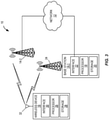
- FIG. 3 illustrates an exemplary wireless network 10 in which these embodiments may be carried out, comprising a network 12 which may also be referred to a core network, network nodes 14-1 and 14-2 which may generally be referred to herein as network nodes 14, and a wireless device (WD) 16.
- the network nodes 14 are, more specifically, radio access nodes and, in this example, base stations.
- the network nodes 14 are also referred to herein as base stations 14.
- base stations are referred to as eNBs. So, the network nodes 14 are also referred to herein as eNBs 14.
- FIG. 3 comprises more detailed views of the network node 14-1 and the WD 16, in accordance with a particular embodiment.
- the network node 14-1 comprises a processor 18, storage 20, an interface 22, and an antenna 24.
- the WD 16 comprises a processor 26, storage 28, an interface 30, and an antenna 32.
- These components may work together in order to provide network node and/or wireless device functionality, such as providing wireless connections in the wireless network 10.
- the wireless network 10 may comprise any number of wired or wireless networks, network nodes, base stations, controllers, wireless devices, relay stations, and/or any other components that may facilitate or participate in the communication of data and/or signals whether via wired or wireless connections.
- the network 12 may comprise one or more Internet Protocol (IP) networks, Public Switched Telephone Networks (PSTNs), packet data networks, optical networks, Wide Area Networks (WANs), Local Area Networks (LANs), Wireless Local Area Networks (WLANs), wired networks, wireless networks, metropolitan area networks, and other networks to enable communication between devices.
- IP Internet Protocol
- PSTNs Public Switched Telephone Networks
- WANs Wide Area Networks
- LANs Local Area Networks
- WLANs Wireless Local Area Networks
- wired networks wireless networks, metropolitan area networks, and other networks to enable communication between devices.
- the network node 14-1 comprises the processor 18, the storage 20, the interface 22, and the antenna 24. For the purposes of illustration, these components are depicted as single boxes located within a single larger box. In practice however, a network node may comprise multiple different physical components that make up a single illustrated component (e.g., the interface 22 may comprise terminals for coupling wires for a wired connection and a radio transceiver for a wireless connection). Similarly, the network node 14-1 may be composed of multiple physically separate components (e.g., a Node B component and a Radio Network Controller (RNC) component, a Base Transceiver Station (BTS) component and a Base Station Controller (BSC) component, etc.), which may each have their own respective processor, storage, and interface components.
- RNC Radio Network Controller
- BTS Base Transceiver Station
- BSC Base Station Controller
- the network node 14-1 comprises multiple separate components (e.g., BTS and BSC components)
- one or more of the separate components may be shared among several network nodes.
- a single RNC may control multiple Node Bs.
- each unique Node B and BSC pair may be a separate network node.
- the network node 14-1 may be configured to support multiple Radio Access Technologies (RATs).
- RATs Radio Access Technologies
- some components may be duplicated (e.g., separate storage 20 for the different RATs) and some components may be reused (e.g., the same antenna 24 may be shared by the RATs).
- the processor 18 may be a combination of one or more of a microprocessor, controller, microcontroller, Central Processing Unit (CPU), digital signal processor, Application Specific Integrated Circuit (ASIC), Field Programmable Gate Array (FPGA), or any other suitable computing device, resource, or combination of hardware, software, and/or encoded logic operable to provide, either alone or in conjunction with, other network node 14-1 components, such as storage 20, and network node 14-1 functionality.
- the processor 18 may execute instructions stored in the storage 20.
- Such functionality may include providing various wireless features discussed herein to a wireless device, such as the WD 16, including any of the features or benefits disclosed herein.
- the storage 20 may comprise any form of volatile or non-volatile computer readable memory including, without limitation, persistent storage, solid state memory, remotely mounted memory, magnetic media, optical media, Random Access Memory (RAM), Read-Only Memory (ROM), removable media, or any other suitable local or remote memory component.
- the storage 20 may store any suitable instructions, data, or information, including software and encoded logic, utilized by the network node 14-1.
- the storage 20 may be used to store any calculations made by the processor 18 and/or any data received via the interface 22.
- the network node 14-1 also comprises the interface 22 which may be used in the wired or wireless communication of signaling and/or data between the network node 14-1, the network 12, and/or the WD 16.
- the interface 22 may perform any formatting, coding, or translating that may be needed to allow the network node 14-1 to send and receive data from the network 12 over a wired connection.
- the interface 22 may also include a radio transmitter and/or receiver that may be coupled to or a part of the antenna 24.
- the radio may receive digital data that is to be sent out to other network nodes or WDs via a wireless connection.
- the radio may convert the digital data into a radio signal having the appropriate channel and bandwidth parameters.
- the radio signal may then be transmitted via the antenna 24 to the appropriate recipient (e.g., the WD 16).
- the antenna 24 may be any type of antenna capable of transmitting and receiving data and/or signals wirelessly.
- the antenna 24 may comprise one or more omni-directional, sector, or panel antennas operable to transmit/receive radio signals.
- An omni-directional antenna may be used to transmit/receive radio signals in any direction
- a sector antenna may be used to transmit/receive radio signals from devices within a particular area
- a panel antenna may be a line of sight antenna used to transmit/receive radio signals in a relatively straight line.
- the WD 16 may be any type of wireless endpoint, wireless machine, mobile station, mobile phone, wireless local loop phone, smartphone, UE, desktop computer, Personal Digital Assistant (PDA), cell phone, tablet, laptop, or Voice over IP (VoIP) phone or handset, which is able to wirelessly send and receive data and/or signals to and from a network node, such as the network node 14-1, and/or other WDs.
- the WD 16 comprises the processor 26, the storage 28, the interface 30, and the antenna 32.
- the components of the WD 16 are depicted as single boxes located within a single larger box; however, in practice a wireless device may comprises multiple different physical components that make up a single illustrated component (e.g., the storage 28 may comprise multiple discrete microchips, each microchip representing a portion of the total storage capacity).
- the processor 26 may be a combination of one or more of a microprocessor, controller, microcontroller, CPU, digital signal processor, ASIC, FPGA, or any other suitable computing device, resource, or combination of hardware, software, and/or encoded logic operable to provide, either alone or in combination with other WD 16 components, such as the storage 28, WD 16 functionality.
- Such functionality may include providing various wireless features discussed herein, including any of the features or benefits disclosed herein.
- the storage 28 may be any form of volatile or non-volatile memory including, without limitation, persistent storage, solid state memory, remotely mounted memory, magnetic media, optical media, RAM, ROM, removable media, or any other suitable local or remote memory component.
- the storage 28 may store any suitable data, instructions, or information, including software and encoded logic, utilized by the WD 16.
- the storage 28 may be used to store any calculations made by the processor 26 and/or any data received via the interface 30.
- the interface 30 may be used in the wireless communication of signaling and/or data between the WD 16 and the network node 14-1.
- the interface 30 may perform any formatting, coding, or translating that may be needed to allow the WD 16 to send and receive data from the network node 14-1 over a wireless connection.
- the interface 30 may also include a radio transmitter and/or receiver that may be coupled to or a part of the antenna 32.
- the radio may receive digital data that is to be sent out to the network node 14-1 via a wireless connection.
- the radio may convert the digital data into a radio signal having the appropriate channel and bandwidth parameters.
- the radio signal may then be transmitted via the antenna 32, to the network node 14-1.
- the antenna 32 may be any type of antenna capable of transmitting and receiving data and/or signals wirelessly.
- the antenna 32 may comprise one or more omni-directional, sector, or panel antennas operable to transmit/receive radio signals.
- the antenna 32 may be considered a part of the interface 30 to the extent that a wireless signal is being used.
- any appropriate steps, methods, or functions may be performed through a computer program product that may, for example, be executed by the components and equipment illustrated in Figure 3 .
- the storage 20 may comprise computer readable means on which a computer program can be stored.
- the computer program may include instructions which cause the processor 18 (and any operatively coupled entities and devices, such as the interface 22 and the storage 20) to execute methods according to embodiments described herein.
- the computer program and/or computer program product may thus provide means for performing any steps herein disclosed.
- Each functional module may comprise software, computer programs, sub-routines, libraries, source code, or any other form of executable instructions that are executed by, for example, a processor.
- each functional module may be implemented in hardware and/or in software.
- one or more or all functional modules may be implemented by the processors 26 and/or 18, possibly in cooperation with the storage 28 and/or 20.
- the processors 26 and/or 18 and the storage 28 and/or 20 may thus be arranged to allow the processors 26 and/or 18 to fetch instructions from the storage 28 and/or 20 and execute the fetched instructions to allow the respective functional module to perform any steps or functions disclosed herein.
- the wireless device 16 is a Third Generation Partnership Project (3GPP) LTE or future variation thereof and, as such, 3GPP terminology is used. Therefore, the wireless device 16 is referred to as UE 16, the suspending network node 14 is referred to as the suspending eNB 14, and the resuming network node 14 is referred to as the resuming eNB 14. Further, in the following example, the eNB 14-1 is the resuming eNB, and the eNB 14-2 is the suspending eNB. The description is made with reference to the signaling diagram in Figure 4 .
- 3GPP Third Generation Partnership Project
- the UE 16 has an established RRC connection with a source eNB 14-2. Due to some trigger (e.g., expiry of an UE inactivity timer), the source eNB 14-2 decides to suspend the RRC connection by sending a RRC Connection Suspend message to the UE 16 (step 100).
- the eNB 14-2 is therefore referred to as the suspending eNB 14-2.
- the UE 16 stores its UE context and transitions to IDLE/SUSPENDED state upon receiving the RRC Connection Suspend message.
- Various triggers may be envisioned that would cause the eNB 14-2 to suspend the RRC connection.
- the RRC Connection Suspend message may contain security related parameters (e.g., Next Hop Chaining Counter (NCC) and security algorithm configuration) which are required when Access Stratum (AS) security is later re-established.
- NCC Next Hop Chaining Counter
- AS Access Stratum
- the suspending eNB 14-2 can assign a GROUP_ID to increase the number of addressable UE contexts.
- the GROUP_ID is either included in the RRC Connection Suspend message or the GROUP_ID is sent to the UE 16 when the RRC connection was initially established, e.g. in the second step of the RRC Connection Establishment procedure.
- the GROUP_ID may also be included, or sent, in the RRC Connection Resume message to allow for change of the GROUP_ID to ensure that the combination of the GROUP_ID and the UE identity within the new cell (i.e., the cell in which the RRC connection is subsequently resumed) is unique within the new cell; i.e., not used for any other UE in the new cell.
- the UE 16 remains in IDLE/SUSPENDED state until new uplink (UL) data arrives (i.e., new data arrives in the uplink buffer of the UE 16) or the UE 16 is paged (step 102). At some later point in time, new data arrives in the uplink buffer at the UE 16 or the UE 16 is being paged by the network 12. This, or any other activity that would require a connection with the UE 16, triggers the UE 16 to resume the RRC connection.
- the UE 16 performs a random access procedure in which the UE 16 transmits a random access preamble (step 104) and, in response, receives a random access response from the eNB 14-1 (step 106).
- the UE 16 resumes its RRC connection by sending an RRC Connection Resume Request message to the eNB 14-1, which is referred to as the target or resuming eNB (step 108).
- the UE 16 includes its Resume ID and an authorization token in the RRC Connection Resume Request message.
- the Resume ID is made up of two or three parts, depending on the embodiment. One part identifies the eNB and cell and another part identifies the suspended UE within a cell. In some embodiments, the Resume ID includes another part that is a group identifier. In some particular embodiments, the Resume ID is a composite identifier made up of the following sub-parts:
- the resuming eNB 14-1 locates the suspending eNB 14-2 based on the ECI and sends a request to retrieve the UE context associated with the UE 16 (step 110).
- the UE context request includes the Resume ID of the UE 16.
- the UE context request may include the C-RNTI and, if included, the GROUP_ID of the UE 16.
- the suspending eNB 14-2 retrieves the UE context associated with the C-RNTI and GROUP_ID (if present) and sends the UE context to the resuming eNB 14-1 (step 112).
- the UE context response also includes the AS security key, the security algorithm configuration, and the authorization token.
- the suspending eNB 14-2 responds with an error message indicating that the Resume ID is missing.
- the resuming eNB 14-1 verifies the authorization token received from the UE 16 in the RRC Connection Resume Request message by matching it to the authorization token received from the suspending eNB 14-2 (step 114).
- the resuming eNB 14-1 activates AS security using the AS security key and the security algorithm configuration received from the suspending eNB 14-2 (step 114).
- the resuming eNB 14-1 sends a RRC Connection Resume message to the UE 16 to indicate that the connection is being resumed (step 116).
- contention resolution may also be performed as part of this step.
- multiple UEs perform random access at the same time and select the same preamble, they will all receive the same random access response and will therefore use the same resources for the uplink transmission.
- the eNB will receive multiple RRC Connection Resume Request messages but it may only be able to decode and respond to one of them.
- the eNB in order for a UE to be able to determine which UE the eNB actually responded to, the eNB includes a copy of the RRC Connection Resume Request in its response. Only a UE which observes a match between the received and transmitted message, i.e., the RRC Connection Resume Request, will declare the random access procedure successful.
- the UE 16 compares the copy of the RRC Connection Resume Request included in the RRC Connection Resume message to a local copy of the RRC Connection Resume Request for purposes of contention resolution. If there is a match between the received copy and the local copy, then the UE 16 will declare the random access procedure successful. Since the RRC Connection Resume Request contains the Resume ID which is unique among UEs, only one UE will be successful. The other UEs will restart from the beginning.
- contention resolution is performed by the Medium Access Control (MAC) layer in the same way as is done today for RRC connection establishment/re-establishment, i.e. the copy of the RRC Connection Resume Request is transmitted in the contention resolution identity MAC control element.
- MAC Medium Access Control
- One problem though is that the size of this control element is fixed to 48 bits which is less than the size of the RRC Connection Resume Request. There are two primary options for handling this problem:
- the claimed invention uses the latter case.
- the contention resolution identity may no longer be unique and there is a small risk that contention resolution succeeds for more than one UE.
- AS security is activated and only the UE with the correct key will be able to decipher and verify the integrity of subsequent messages, this situation can be detected and resolved.
- Copying parts of the content from the RRC Connection Resume Request message can be done, e.g.:
- the claimed invention uses the truncation option, i.e. truncating the CCCH SDU to the size of 48 bits.
- the message type included in the RRC message is kept, and it can be ensured that the contention resolution identities for legacy RRC Connection Request, RRC Connection Reestablishment Request, and RRC Connection Resume Request can be distinguished by means of the message type of the UL-CCCH included in the RRC message.
- truncated SDU from CCCH is used as contention resolution identity, ambiguity is avoided for legacy UEs which do not implement or understand the new functionality; i.e., legacy UEs can be kept unaffected.
- conflict can be detected and resolved by verification of AS integrity as described above.
- the risk of conflicts can be reduced by arranging the information included in the RRC Connection Resume Request in an order such that entropy in the contention resolution identity MAC control element becomes high; i.e., unlikely that more than one UE uses the same contention resolution identity at the same time in the same cell.
- the first part can be C-RNTI followed by GROUP_ID (if GROUP_ID is needed/used) and ECI.
- the bit orders in the C-RNTI, GROUP_ID, and ECI parts can be reversed so that, e.g., the cell identity part of ECI comes before the eNB part of ECI. Reversing the bit order of the C-RNTI and GROUP_ID parts is assuming that they are allocated incrementally and the distribution is biased towards smaller values. Alternatively to reversing bit orders of C-RNTI and GROUP_ID, the allocation algorithm can be adapted to achieve the same result.
- the UE may acknowledge the reception by sending a RRC Connection Resume Complete message (step 118). Note that step 118 is optional.
- the UE 16 is then in the RRC CONNECTED state and may then transmit uplink data (step 120) and receive downlink data (step 122) using the resumed RRC connection.
- the suspending eNB 14-2 is different from the resuming eNB 14-1, i.e., inter-eNB RRC resume is assumed.
- the suspending and resuming eNBs 14 are identical, or the same eNB 14, i.e., assuming an intra-eNB RRC resume, the procedure is the same except that steps 110 and 112 are performed internally in the eNB 14.
- Each functional module may comprise software, computer programs, sub-routines, libraries, source code, or any other form of executable instructions that are executed by, for example, a processor.
- each functional module may be implemented in hardware and/or in software.
- one or more or all functional modules may be implemented by the processors 26 and/or 18, possibly in cooperation with the storage 28 and/or 20.
- the processors 26 and/or 18 and the storage 28 and/or 20 may thus be arranged to allow the processors 26 and/or 18 to fetch instructions from the storage 28 and/or 20 and execute the fetched instructions to allow the respective functional module to perform any steps or functions disclosed herein.
- Figures 5 through 7 illustrate example embodiments of the wireless device 16 and the network node 14.
- the wireless device 16 includes a first receiving module 34-1, a transmitting module 34-2, and a second receiving module 34-3.
- the first receiving module 34-1 is operable to receive, from a first network node 14, a first message that instructs the wireless device 16 to suspend a connection between the wireless device 16 and the wireless network 10.
- the wireless device 16 Upon receiving the first message, the wireless device 16 stores a wireless device context (i.e., a UE context) of the wireless device 16 and enters a suspended mode of operation.
- a wireless device context i.e., a UE context
- the transmitting module 34-2 is operable to, upon an occurrence of a triggering event, transmit, to a second network node 14, a second message that requests that the connection between the wireless device 16 and the wireless network 16 be resumed.
- the second message includes a resume identifier, where the resume identifier includes a part that identifies the first network node 14 to which the wireless device 16 was connected upon suspending the connection and a part that identifies the wireless device 16.
- the second receiving module 34-3 is operable to receive, from the second network node 14, a third message that indicates that the connection between the wireless device 16 and the wireless network 10 is being resumed using the stored wireless device context of the wireless device 16.
- the network node 14 includes a receiving module 36-1, an obtaining module 36-2, and a transmitting module 36-3.
- the receiving module 36-1 is operable to receive, from a wireless device 16, a first message that requests that a connection between the wireless device 16 and the wireless network 10 be resumed.
- the first message includes a resume identifier, where the resume identifier includes a part that identifies a network node 14 and cell to which the wireless device 16 was connected upon suspending the connection and a part that identifies the wireless device 16 within the cell.
- the obtaining module 36-2 is operable to obtain, from the network node 14 identified by the resume identifier, a wireless device context of the wireless device 16 previously stored upon suspending the connection between the wireless device 16 and the wireless network 10.
- the transmitting module 36-3 is operable to transmit, to the wireless device 16, a second message that indicates that the connection between the wireless device 16 and the wireless network 10 is being resumed using the stored wireless device context of the wireless device 16.
- Figure 7 is a schematic block diagram that illustrates a virtualized embodiment of the base station 14 according to some embodiments of the present disclosure.
- Other types of network nodes may have similar architectures (particularly with respect to including processor(s), memory, and a network interface).
- a "virtualized" base station 14 is a base station 14 in which at least a portion of the functionality of the base station 14 is implemented as a virtual component (e.g., via a virtual machine(s) executing on a physical processing node(s) in a network(s)).
- the base station 14 optionally includes a control system 38 that includes the processor 18, the storage 20, and the network interface 22A, as described above.
- the base station 14 also includes a transceiver 22B, which may also be referred to as a radio interface, that includes one or more transmitters 40 and one or more receivers 42 coupled to a number of antennas 24.
- the control system 38 (if present) is connected to the transceiver 22B via, for example, an optical cable or the like.
- the control system 38 (if present) is connected to one or more processing nodes 44 coupled to or included as part of a network(s) 46 via the network interface 22A.
- the transceiver 22B is connected to the one or more processing nodes 44 via a network interface(s).
- Each processing node 44 includes one or more processors 48 (e.g., CPUs, ASICs, FPGAs, and/or the like), storage 50 (e.g., memory), and a network interface 52.
- functions 54 of the base station 14 described herein are implemented at the one or more processing nodes 44 or distributed across the control system 38 (if present) and the one or more processing nodes 44 in any desired manner.
- some or all of the functions 54 of the base station 14 described herein are implemented as virtual components executed by one or more virtual machines implemented in a virtual environment(s) hosted by the processing node(s) 44.
- additional signaling or communication between the processing node(s) 44 and the control system 38 (if present) or alternatively the transceiver 22B is used in order to carry out at least some of the desired functions.
- the control system 38 may not be included, in which case the transceiver 22B communicates directly with the processing node(s) 44 via an appropriate network interface(s).
Landscapes
- Engineering & Computer Science (AREA)
- Computer Networks & Wireless Communication (AREA)
- Signal Processing (AREA)
- Computer Security & Cryptography (AREA)
- Computer Hardware Design (AREA)
- Computing Systems (AREA)
- General Engineering & Computer Science (AREA)
- Mobile Radio Communication Systems (AREA)
Claims (11)
- Procédé de fonctionnement d'un dispositif sans fil (16) dans un réseau sans fil (10), comprenant :la réception (100), depuis un premier nœud de réseau (14), d'un premier message qui instruit au dispositif sans fil (16) de suspendre une connexion entre le dispositif sans fil (16) et le réseau sans fil (10), dans lequel, à la réception (100) du premier message, le dispositif sans fil (16) stocke un contexte de dispositif sans fil du dispositif sans fil (16) et entre dans un mode de fonctionnement suspendu ;lors d'une survenance d'un événement de déclenchement, la transmission (108), à un deuxième nœud de réseau (14), d'un deuxième message qui demande la reprise de la connexion entre le dispositif sans fil (16) et le réseau sans fil (10), le deuxième message comprenant un identifiant de reprise et l'identifiant de reprise comprenant :une partie qui identifie le premier nœud de réseau (14) auquel le dispositif sans fil (16) était connecté lors de la suspension de la connexion ; etune partie qui identifie le dispositif sans fil (16) ; etla réception (116), depuis le deuxième nœud de réseau (14), d'un troisième message qui indique la reprise de la connexion entre le dispositif sans fil (16) et le réseau sans fil (10) en utilisant le contexte de dispositif sans fil stocké du dispositif sans fil (16), dans lequel un élément de commande de commande d'accès au support, MAC, associé au troisième message comprend une copie d'une portion du deuxième message qui demande la reprise de la connexion entre le dispositif sans fil (16) et le réseau sans fil (10), etdans lequel le deuxième message est transmis dans une unité de données de service de canal de commande commun de liaison montante, et la portion du deuxième message est fournie par la troncation de l'unité de données de service de canal de commande commun de liaison montante à 48 bits.
- Procédé de fonctionnement d'un nœud de réseau (14) dans un réseau sans fil (10), comprenant :la réception (108), depuis un dispositif sans fil (16), d'un premier message qui demande la reprise d'une connexion entre le dispositif sans fil (16) et le réseau sans fil (10), le premier message comprenant un identifiant de reprise et l'identifiant de reprise comprenant :une partie qui identifie un nœud de réseau auquel le dispositif sans fil (16) était connecté lors de la suspension de la connexion ; etune partie qui identifie le dispositif sans fil (16) ; etl'obtention (110-112), depuis le nœud de réseau identifié par l'identifiant de reprise, d'un contexte de dispositif sans fil du dispositif sans fil (16) préalablement stocké lors de la suspension de la connexion entre le dispositif sans fil (16) et le réseau sans fil (10) ; etla transmission (116), au dispositif sans fil (16), d'un deuxième message qui indique la reprise de la connexion entre le dispositif sans fil (16) et le réseau sans fil (10) en utilisant le contexte de dispositif sans fil stocké du dispositif sans fil (16),dans lequel un élément de commande de commande d'accès au support, MAC, associé au deuxième message comprend une copie d'une portion du premier message qui demande la reprise de la connexion entre le dispositif sans fil (16) et le réseau sans fil (10), etdans lequel le premier message est transmis dans une unité de données de service de canal de commande commun de liaison montante, et la portion du premier message est fournie par la troncation de l'unité de données de service de canal de commande commun de liaison montante à 48 bits.
- Procédé selon la revendication 2, dans lequel :le nœud de réseau (14) est un premier nœud de réseau (14-1) et le nœud de réseau identifié par l'identifiant de reprise est un deuxième nœud de réseau (14-2), dans lequel le premier nœud de réseau (14-1) et le deuxième nœud de réseau (14-2) sont des nœuds de réseau différents ; etl'obtention (110-112) du contexte de dispositif sans fil du dispositif sans fil (16) comprend :l'envoi (110) d'une demande du contexte de dispositif sans fil du dispositif sans fil (16) au deuxième nœud de réseau (14-2), dans lequel la demande du contexte de dispositif sans fil du dispositif sans fil (16) comprend l'identifiant de reprise ; etla réception (112) du contexte de dispositif sans fil du dispositif sans fil (16) depuis le deuxième nœud de réseau (14-2).
- Procédé selon la revendication 2 ou 3, dans lequel le deuxième message comprend un jeton d'autorisation qui permet au nœud de réseau (14) d'identifier en toute sécurité le dispositif sans fil (16), et le procédé comprend en outre la vérification (114) du jeton d'autorisation.
- Procédé selon l'une quelconque des revendications précédentes, dans lequel le réseau sans fil (10) est un réseau d'évolution à long terme, LTE, et :la partie de l'identifiant de reprise qui identifie le premier nœud de réseau (14) est un identifiant, ID, de cellule de réseau d'accès radio terrestre universel évolué, E-UTRAN, ECI ; etla partie de l'identifiant de reprise qui identifie le dispositif sans fil (16) est un identifiant temporaire de réseau radio cellulaire, C-RNTI.
- Procédé selon l'une quelconque des revendications précédentes, dans lequel l'identifiant de reprise comprend en outre une partie qui contient un identifiant de groupe attribué au dispositif sans fil (16).
- Procédé selon la revendication 6, dans lequel un séquencement des parties à l'intérieur de l'identifiant de reprise est tel que :la partie de l'identifiant de reprise qui identifie le dispositif sans fil (16) survient en premier dans le séquencement ;la partie qui contient l'identifiant de groupe attribué au dispositif sans fil (16) survient après la partie de l'identifiant de reprise qui identifie le dispositif sans fil (16) dans le séquencement ; etla partie de l'identifiant de reprise qui identifie le premier nœud de réseau (14) survient après la partie qui contient l'identifiant de groupe attribué au dispositif sans fil (16) dans le séquencement.
- Procédé selon la revendication 7, dans lequel des ordres de bits à l'intérieur des parties de l'identifiant de reprise sont inversés.
- Procédé selon la revendication 1 ou l'une quelconque des revendications 5 à 8 dépendant de la revendication 1, dans lequel la copie d'au moins la portion du deuxième message inclut au moins l'un parmi :la partie de l'identifiant de reprise qui identifie le dispositif sans fil (16) ;un jeton d'autorisation qui permet au deuxième nœud de réseau (14) d'identifier en toute sécurité le dispositif sans fil (16) ; etune partie de l'identifiant de reprise qui contient un identifiant de groupe attribué au dispositif sans fil (16) .
- Dispositif sans fil (16) pour un réseau sans fil (10), le dispositif sans fil (16) étant apte à :recevoir, depuis un premier nœud de réseau (14), un premier message qui instruit au dispositif sans fil (16) de suspendre une connexion entre le dispositif sans fil (16) et le réseau sans fil (10), dans lequel, à la réception du premier message, le dispositif sans fil (16) stocke un contexte de dispositif sans fil du dispositif sans fil (16) et entre dans un mode de fonctionnement suspendu ;lors d'une survenance d'un événement de déclenchement, transmettre, à un deuxième nœud de réseau (14), un deuxième message qui demande la reprise de la connexion entre le dispositif sans fil (16) et le réseau sans fil (10), le deuxième message comprenant un identifiant de reprise et l'identifiant de reprise comprenant :une partie qui identifie le premier nœud de réseau (14) auquel le dispositif sans fil (16) était connecté lors de la suspension de la connexion ; etune partie qui identifie le dispositif sans fil (16) ; etrecevoir, depuis le deuxième nœud de réseau (14), un troisième message qui indique la reprise de la connexion entre le dispositif sans fil (16) et le réseau sans fil (10) en utilisant le contexte de dispositif sans fil stocké du dispositif sans fil (16),dans lequel un élément de commande de commande d'accès au support, MAC, associé au troisième message comprend une copie d'une portion du deuxième message qui demande la reprise de la connexion entre le dispositif sans fil (16) et le réseau sans fil (10), etdans lequel le deuxième message est transmis dans une unité de données de service de canal de commande commun de liaison montante, et la portion du deuxième message est fournie par la troncation de l'unité de données de service de canal de commande commun de liaison montante à 48 bits.
- Nœud de réseau (14) pour un réseau sans fil (10), le nœud de réseau (14) étant apte à :recevoir, depuis un dispositif sans fil (16), un premier message qui demande la reprise d'une connexion entre le dispositif sans fil (16) et le réseau sans fil (10), le premier message comprenant un identifiant de reprise et l'identifiant de reprise comprenant :une partie qui identifie un nœud de réseau auquel le dispositif sans fil (16) était connecté lors de la suspension de la connexion ; etune partie qui identifie le dispositif sans fil (16) ; etobtenir, depuis le nœud de réseau identifié par l'identifiant de reprise, un contexte de dispositif sans fil du dispositif sans fil (16) préalablement stocké lors de la suspension de la connexion entre le dispositif sans fil (16) et le réseau sans fil (10) ; ettransmettre, au dispositif sans fil (16), un deuxième message qui indique la reprise de la connexion entre le dispositif sans fil (16) et le réseau sans fil (10) en utilisant le contexte de dispositif sans fil stocké du dispositif sans fil (16),dans lequel un élément de commande de commande d'accès au support, MAC, associé au deuxième message comprend une copie d'une portion du premier message qui demande la reprise de la connexion entre le dispositif sans fil (16) et le réseau sans fil (10), etdans lequel le premier message est transmis dans une unité de données de service de canal de commande commun de liaison montante, et la portion du premier message est fournie par la troncation de l'unité de données de service de canal de commande commun de liaison montante à 48 bits.
Priority Applications (2)
| Application Number | Priority Date | Filing Date | Title |
|---|---|---|---|
| EP21209383.5A EP3979764B1 (fr) | 2015-11-17 | 2016-11-15 | Identificateur ue dans une reprise de rrc |
| PL16801591T PL3378273T3 (pl) | 2015-11-17 | 2016-11-15 | Sposoby i aparaty do wykonywania procedury wznawiania |
Applications Claiming Priority (2)
| Application Number | Priority Date | Filing Date | Title |
|---|---|---|---|
| US201562256378P | 2015-11-17 | 2015-11-17 | |
| PCT/IB2016/056867 WO2017085621A1 (fr) | 2015-11-17 | 2016-11-15 | Identifiant d'ue dans une reprise de rrc |
Related Child Applications (2)
| Application Number | Title | Priority Date | Filing Date |
|---|---|---|---|
| EP21209383.5A Division-Into EP3979764B1 (fr) | 2015-11-17 | 2016-11-15 | Identificateur ue dans une reprise de rrc |
| EP21209383.5A Division EP3979764B1 (fr) | 2015-11-17 | 2016-11-15 | Identificateur ue dans une reprise de rrc |
Publications (2)
| Publication Number | Publication Date |
|---|---|
| EP3378273A1 EP3378273A1 (fr) | 2018-09-26 |
| EP3378273B1 true EP3378273B1 (fr) | 2022-02-09 |
Family
ID=57396771
Family Applications (2)
| Application Number | Title | Priority Date | Filing Date |
|---|---|---|---|
| EP16801591.5A Active EP3378273B1 (fr) | 2015-11-17 | 2016-11-15 | Procédés et dispositifs pour exécuter une procédure resume |
| EP21209383.5A Active EP3979764B1 (fr) | 2015-11-17 | 2016-11-15 | Identificateur ue dans une reprise de rrc |
Family Applications After (1)
| Application Number | Title | Priority Date | Filing Date |
|---|---|---|---|
| EP21209383.5A Active EP3979764B1 (fr) | 2015-11-17 | 2016-11-15 | Identificateur ue dans une reprise de rrc |
Country Status (8)
| Country | Link |
|---|---|
| US (2) | US10945303B2 (fr) |
| EP (2) | EP3378273B1 (fr) |
| KR (1) | KR102067012B1 (fr) |
| DK (1) | DK3378273T3 (fr) |
| ES (1) | ES2907677T3 (fr) |
| HU (1) | HUE058340T2 (fr) |
| PL (1) | PL3378273T3 (fr) |
| WO (1) | WO2017085621A1 (fr) |
Families Citing this family (19)
| Publication number | Priority date | Publication date | Assignee | Title |
|---|---|---|---|---|
| US20170330153A1 (en) * | 2014-05-13 | 2017-11-16 | Monster Worldwide, Inc. | Search Extraction Matching, Draw Attention-Fit Modality, Application Morphing, and Informed Apply Apparatuses, Methods and Systems |
| WO2017135676A1 (fr) * | 2016-02-02 | 2017-08-10 | Lg Electronics Inc. | Procédé et appareil de radiomessagerie avec un id de reprise pour un équipement d'utilisateur interrompu dans un système de communication sans fil |
| KR20180035638A (ko) * | 2016-09-29 | 2018-04-06 | 삼성전자주식회사 | RRC Inactive 및 active 상태에서 data 전송 결정 및 방법 및 장치 |
| GB2555784A (en) * | 2016-11-04 | 2018-05-16 | Nec Corp | Communication system |
| US11184938B2 (en) * | 2017-03-24 | 2021-11-23 | Lg Electronics Inc. | Method and device for requesting RRC connection |
| CN110741725B (zh) * | 2017-06-16 | 2023-06-02 | 瑞典爱立信有限公司 | 在无线通信系统中恢复连接 |
| CN109548170A (zh) * | 2017-07-24 | 2019-03-29 | 中兴通讯股份有限公司 | 一种连接建立方法、网元、存储介质及系统 |
| EP3654697B1 (fr) * | 2017-09-04 | 2022-02-16 | Guangdong Oppo Mobile Telecommunications Corp., Ltd. | Procédés et dispositifs pour des communications sans fil |
| CN111418260B (zh) * | 2017-09-28 | 2022-10-04 | 联想(北京)有限公司 | 执行恢复请求过程的方法和装置 |
| WO2019101189A1 (fr) | 2017-11-27 | 2019-05-31 | Guangdong Oppo Mobile Telecommunications Corp., Ltd. | Équipement d'utilisateur et son procédé de communication sans fil |
| CN110710241A (zh) * | 2018-02-23 | 2020-01-17 | Oppo广东移动通信有限公司 | 完整性校验方法、网络设备、终端设备及计算机存储介质 |
| JP7139434B2 (ja) * | 2018-03-26 | 2022-09-20 | テレフオンアクチーボラゲット エルエム エリクソン(パブル) | Rrcコネクション再開時のセキュリティ検証 |
| CN110351894B (zh) | 2018-04-04 | 2024-06-18 | 北京三星通信技术研究有限公司 | 一种认证ue的方法和设备 |
| KR102143023B1 (ko) | 2018-04-16 | 2020-08-10 | 텔레호낙티에볼라게트 엘엠 에릭슨(피유비엘) | 비활성 상태로부터의 rrc 재개를 위한 보안 핸들링 |
| WO2019216749A1 (fr) * | 2018-05-09 | 2019-11-14 | 엘지전자 주식회사 | Procédé d'émission de signal associé à une pdu dans un système de communication sans fil et dispositif correspondant |
| EP3657898B1 (fr) * | 2018-10-31 | 2023-04-05 | ASUSTek Computer Inc. | Procédé et appareil de transmission utilisant des ressources de liaison montante préconfigurées dans un système de communication sans fil |
| WO2020165843A1 (fr) * | 2019-02-14 | 2020-08-20 | Telefonaktiebolaget Lm Ericsson (Publ) | Procédés de gestion d'informations de contexte pour une transmission de données précoce à terminaison mobile |
| EP3726923A1 (fr) | 2019-03-28 | 2020-10-21 | LG Electronics Inc. | Procédé de fonctionnement d'un équipement utilisateur de transmission de liaison latérale pour la transmission de messages de rrc associés à une rlf après une reprise de la rrc dans un système de communication sans fil |
| WO2021162597A1 (fr) * | 2020-02-14 | 2021-08-19 | Telefonaktiebolaget Lm Ericsson (Publ) | Nœuds de réseau et procédés dans un réseau d'accès radio pour améliorer la procédure de reprise de rrc |
Family Cites Families (8)
| Publication number | Priority date | Publication date | Assignee | Title |
|---|---|---|---|---|
| JP4625123B2 (ja) | 2008-12-11 | 2011-02-02 | 株式会社エヌ・ティ・ティ・ドコモ | 移動通信方法及び無線基地局 |
| KR101829832B1 (ko) | 2010-03-26 | 2018-02-19 | 엘지전자 주식회사 | 무선 통신 시스템에서 신호 송수신 방법 및 이를 위한 장치 |
| EP2645804B1 (fr) * | 2012-03-27 | 2017-12-20 | BlackBerry Limited | Rétablissement d'une connexion RRC suspendue à un ENB différent |
| WO2013144613A1 (fr) * | 2012-03-27 | 2013-10-03 | Research In Motion Limited | Enb stockant des informations de configuration rrc au niveau d'un autre composant de réseau |
| US9155121B2 (en) * | 2012-03-27 | 2015-10-06 | Blackberry Limited | Re-establishment of suspended RRC connection at a different eNB |
| GB2515456B (en) * | 2013-04-05 | 2015-11-11 | Broadcom Corp | Resource Control |
| WO2016123809A1 (fr) * | 2015-02-06 | 2016-08-11 | 华为技术有限公司 | Procédé et dispositif d'optimisation de signalisation |
| EP4236570A3 (fr) * | 2016-05-12 | 2023-11-15 | Samsung Electronics Co., Ltd. | Procédé et appareil de connexion lumineuse à utiliser dans un système de communication sans fil |
-
2016
- 2016-11-15 DK DK16801591.5T patent/DK3378273T3/da active
- 2016-11-15 US US15/981,461 patent/US10945303B2/en active Active
- 2016-11-15 EP EP16801591.5A patent/EP3378273B1/fr active Active
- 2016-11-15 WO PCT/IB2016/056867 patent/WO2017085621A1/fr active Application Filing
- 2016-11-15 ES ES16801591T patent/ES2907677T3/es active Active
- 2016-11-15 EP EP21209383.5A patent/EP3979764B1/fr active Active
- 2016-11-15 KR KR1020187016959A patent/KR102067012B1/ko active IP Right Grant
- 2016-11-15 PL PL16801591T patent/PL3378273T3/pl unknown
- 2016-11-15 HU HUE16801591A patent/HUE058340T2/hu unknown
-
2023
- 2023-05-01 US US18/141,489 patent/US20230262830A1/en active Pending
Non-Patent Citations (1)
| Title |
|---|
| INTEL CORPORATION: "Discussion on user plane solution of AS context reuse for NB-IOT", vol. RAN WG2, no. Anaheim, USA; 20151116 - 20151120, 16 November 2015 (2015-11-16), XP051005808, Retrieved from the Internet <URL:http://www.3gpp.org/ftp/Meetings_3GPP_SYNC/RAN2/Docs/> [retrieved on 20151116] * |
Also Published As
| Publication number | Publication date |
|---|---|
| KR20180084102A (ko) | 2018-07-24 |
| HUE058340T2 (hu) | 2022-07-28 |
| DK3378273T3 (da) | 2022-02-21 |
| US10945303B2 (en) | 2021-03-09 |
| WO2017085621A1 (fr) | 2017-05-26 |
| EP3979764C0 (fr) | 2024-08-21 |
| PL3378273T3 (pl) | 2022-06-13 |
| ES2907677T3 (es) | 2022-04-26 |
| KR102067012B1 (ko) | 2020-01-17 |
| EP3378273A1 (fr) | 2018-09-26 |
| US20230262830A1 (en) | 2023-08-17 |
| EP3979764B1 (fr) | 2024-08-21 |
| EP3979764A1 (fr) | 2022-04-06 |
| US20190357296A1 (en) | 2019-11-21 |
Similar Documents
| Publication | Publication Date | Title |
|---|---|---|
| US20230262830A1 (en) | Ue identifier in rrc resume | |
| CN110786065B (zh) | 在ran非活动模式下的下行链路传输 | |
| EP3689096B1 (fr) | Procédés et dispositifs pour la préservation d'un pdcp nr lors d'une reprise/suspension de rrc | |
| US9924460B2 (en) | Network nodes, a user equipment and methods therein for handling a connection between the user equipment and a wireless communications network | |
| US11672044B2 (en) | UE identifier in RRC resume | |
| US20190208411A1 (en) | Security framework for msg3 and msg4 in early data transmission | |
| US10812973B2 (en) | System and method for communicating with provisioned security protection | |
| TW201831031A (zh) | 處理無線通訊系統中狀態不匹配的裝置及方法 | |
| TW202226868A (zh) | 用於5g新無線電系統中之上行鏈路傳輸之方法 | |
| JP7405265B2 (ja) | 端末装置及び基地局 | |
| WO2019202455A1 (fr) | Gestion du temps d'attente de rejet | |
| EP3874821A1 (fr) | Équipement utilisateur, noeud d'accès source, noeud d'accès cible, et procédés exécutés dans un réseau de communications sans fil pour gérer des paquets de données lors d'un transfert | |
| US11212092B2 (en) | Optimized security key refresh procedure for 5G MC | |
| US20140335864A1 (en) | Radio communication system, radio base station, radio terminal and radio communication method | |
| TWI670985B (zh) | 處理雙連結的裝置及方法 | |
| US9820331B1 (en) | UE-context release in response to failure of air interface communication | |
| US10560870B2 (en) | Device and method of handling cellular-WLAN aggregation | |
| EP3844998B1 (fr) | Transfert de contexte d'équipement utilisateur sur radiomessagerie de réseau d'accès radio | |
| US20200252842A1 (en) | Managing cell group configuration in disaggregated base station architecture | |
| WO2020070719A1 (fr) | Gestion d'informations de capacité de dispositif sans fil dans des réseaux de communication sans fil | |
| WO2021101432A1 (fr) | Passage d'informations entre des nœuds de ran ne comprenant pas complètement la totalité de leur contenu | |
| US20130244674A1 (en) | Mobile terminal, radio base station, control method for a mobile terminal and method for a radio base station |
Legal Events
| Date | Code | Title | Description |
|---|---|---|---|
| STAA | Information on the status of an ep patent application or granted ep patent |
Free format text: STATUS: UNKNOWN |
|
| STAA | Information on the status of an ep patent application or granted ep patent |
Free format text: STATUS: THE INTERNATIONAL PUBLICATION HAS BEEN MADE |
|
| PUAI | Public reference made under article 153(3) epc to a published international application that has entered the european phase |
Free format text: ORIGINAL CODE: 0009012 |
|
| STAA | Information on the status of an ep patent application or granted ep patent |
Free format text: STATUS: REQUEST FOR EXAMINATION WAS MADE |
|
| 17P | Request for examination filed |
Effective date: 20180601 |
|
| AK | Designated contracting states |
Kind code of ref document: A1 Designated state(s): AL AT BE BG CH CY CZ DE DK EE ES FI FR GB GR HR HU IE IS IT LI LT LU LV MC MK MT NL NO PL PT RO RS SE SI SK SM TR |
|
| AX | Request for extension of the european patent |
Extension state: BA ME |
|
| DAV | Request for validation of the european patent (deleted) | ||
| DAX | Request for extension of the european patent (deleted) | ||
| STAA | Information on the status of an ep patent application or granted ep patent |
Free format text: STATUS: EXAMINATION IS IN PROGRESS |
|
| 17Q | First examination report despatched |
Effective date: 20210309 |
|
| REG | Reference to a national code |
Ref country code: DE Ref legal event code: R079 Ref document number: 602016068994 Country of ref document: DE Free format text: PREVIOUS MAIN CLASS: H04W0076040000 Ipc: H04W0076270000 |
|
| GRAP | Despatch of communication of intention to grant a patent |
Free format text: ORIGINAL CODE: EPIDOSNIGR1 |
|
| STAA | Information on the status of an ep patent application or granted ep patent |
Free format text: STATUS: GRANT OF PATENT IS INTENDED |
|
| RIC1 | Information provided on ipc code assigned before grant |
Ipc: H04L 29/06 20060101ALN20210920BHEP Ipc: H04W 4/70 20180101ALN20210920BHEP Ipc: H04W 12/06 20210101ALI20210920BHEP Ipc: H04W 76/27 20180101AFI20210920BHEP |
|
| INTG | Intention to grant announced |
Effective date: 20211020 |
|
| GRAS | Grant fee paid |
Free format text: ORIGINAL CODE: EPIDOSNIGR3 |
|
| GRAA | (expected) grant |
Free format text: ORIGINAL CODE: 0009210 |
|
| STAA | Information on the status of an ep patent application or granted ep patent |
Free format text: STATUS: THE PATENT HAS BEEN GRANTED |
|
| AK | Designated contracting states |
Kind code of ref document: B1 Designated state(s): AL AT BE BG CH CY CZ DE DK EE ES FI FR GB GR HR HU IE IS IT LI LT LU LV MC MK MT NL NO PL PT RO RS SE SI SK SM TR |
|
| REG | Reference to a national code |
Ref country code: GB Ref legal event code: FG4D |
|
| REG | Reference to a national code |
Ref country code: CH Ref legal event code: EP Ref country code: AT Ref legal event code: REF Ref document number: 1468285 Country of ref document: AT Kind code of ref document: T Effective date: 20220215 |
|
| REG | Reference to a national code |
Ref country code: DK Ref legal event code: T3 Effective date: 20220214 |
|
| REG | Reference to a national code |
Ref country code: DE Ref legal event code: R096 Ref document number: 602016068994 Country of ref document: DE |
|
| REG | Reference to a national code |
Ref country code: IE Ref legal event code: FG4D |
|
| REG | Reference to a national code |
Ref country code: FI Ref legal event code: FGE |
|
| REG | Reference to a national code |
Ref country code: NL Ref legal event code: FP |
|
| REG | Reference to a national code |
Ref country code: SE Ref legal event code: TRGR |
|
| REG | Reference to a national code |
Ref country code: RO Ref legal event code: EPE |
|
| REG | Reference to a national code |
Ref country code: ES Ref legal event code: FG2A Ref document number: 2907677 Country of ref document: ES Kind code of ref document: T3 Effective date: 20220426 |
|
| REG | Reference to a national code |
Ref country code: LT Ref legal event code: MG9D |
|
| REG | Reference to a national code |
Ref country code: AT Ref legal event code: MK05 Ref document number: 1468285 Country of ref document: AT Kind code of ref document: T Effective date: 20220209 |
|
| REG | Reference to a national code |
Ref country code: HU Ref legal event code: AG4A Ref document number: E058340 Country of ref document: HU |
|
| PG25 | Lapsed in a contracting state [announced via postgrant information from national office to epo] |
Ref country code: RS Free format text: LAPSE BECAUSE OF FAILURE TO SUBMIT A TRANSLATION OF THE DESCRIPTION OR TO PAY THE FEE WITHIN THE PRESCRIBED TIME-LIMIT Effective date: 20220209 Ref country code: PT Free format text: LAPSE BECAUSE OF FAILURE TO SUBMIT A TRANSLATION OF THE DESCRIPTION OR TO PAY THE FEE WITHIN THE PRESCRIBED TIME-LIMIT Effective date: 20220609 Ref country code: NO Free format text: LAPSE BECAUSE OF FAILURE TO SUBMIT A TRANSLATION OF THE DESCRIPTION OR TO PAY THE FEE WITHIN THE PRESCRIBED TIME-LIMIT Effective date: 20220509 Ref country code: LT Free format text: LAPSE BECAUSE OF FAILURE TO SUBMIT A TRANSLATION OF THE DESCRIPTION OR TO PAY THE FEE WITHIN THE PRESCRIBED TIME-LIMIT Effective date: 20220209 Ref country code: HR Free format text: LAPSE BECAUSE OF FAILURE TO SUBMIT A TRANSLATION OF THE DESCRIPTION OR TO PAY THE FEE WITHIN THE PRESCRIBED TIME-LIMIT Effective date: 20220209 Ref country code: BG Free format text: LAPSE BECAUSE OF FAILURE TO SUBMIT A TRANSLATION OF THE DESCRIPTION OR TO PAY THE FEE WITHIN THE PRESCRIBED TIME-LIMIT Effective date: 20220509 |
|
| PG25 | Lapsed in a contracting state [announced via postgrant information from national office to epo] |
Ref country code: LV Free format text: LAPSE BECAUSE OF FAILURE TO SUBMIT A TRANSLATION OF THE DESCRIPTION OR TO PAY THE FEE WITHIN THE PRESCRIBED TIME-LIMIT Effective date: 20220209 Ref country code: GR Free format text: LAPSE BECAUSE OF FAILURE TO SUBMIT A TRANSLATION OF THE DESCRIPTION OR TO PAY THE FEE WITHIN THE PRESCRIBED TIME-LIMIT Effective date: 20220510 Ref country code: AT Free format text: LAPSE BECAUSE OF FAILURE TO SUBMIT A TRANSLATION OF THE DESCRIPTION OR TO PAY THE FEE WITHIN THE PRESCRIBED TIME-LIMIT Effective date: 20220209 |
|
| PG25 | Lapsed in a contracting state [announced via postgrant information from national office to epo] |
Ref country code: IS Free format text: LAPSE BECAUSE OF FAILURE TO SUBMIT A TRANSLATION OF THE DESCRIPTION OR TO PAY THE FEE WITHIN THE PRESCRIBED TIME-LIMIT Effective date: 20220609 |
|
| PG25 | Lapsed in a contracting state [announced via postgrant information from national office to epo] |
Ref country code: SM Free format text: LAPSE BECAUSE OF FAILURE TO SUBMIT A TRANSLATION OF THE DESCRIPTION OR TO PAY THE FEE WITHIN THE PRESCRIBED TIME-LIMIT Effective date: 20220209 Ref country code: SK Free format text: LAPSE BECAUSE OF FAILURE TO SUBMIT A TRANSLATION OF THE DESCRIPTION OR TO PAY THE FEE WITHIN THE PRESCRIBED TIME-LIMIT Effective date: 20220209 Ref country code: EE Free format text: LAPSE BECAUSE OF FAILURE TO SUBMIT A TRANSLATION OF THE DESCRIPTION OR TO PAY THE FEE WITHIN THE PRESCRIBED TIME-LIMIT Effective date: 20220209 Ref country code: CZ Free format text: LAPSE BECAUSE OF FAILURE TO SUBMIT A TRANSLATION OF THE DESCRIPTION OR TO PAY THE FEE WITHIN THE PRESCRIBED TIME-LIMIT Effective date: 20220209 |
|
| REG | Reference to a national code |
Ref country code: DE Ref legal event code: R097 Ref document number: 602016068994 Country of ref document: DE |
|
| PG25 | Lapsed in a contracting state [announced via postgrant information from national office to epo] |
Ref country code: AL Free format text: LAPSE BECAUSE OF FAILURE TO SUBMIT A TRANSLATION OF THE DESCRIPTION OR TO PAY THE FEE WITHIN THE PRESCRIBED TIME-LIMIT Effective date: 20220209 |
|
| PLBE | No opposition filed within time limit |
Free format text: ORIGINAL CODE: 0009261 |
|
| STAA | Information on the status of an ep patent application or granted ep patent |
Free format text: STATUS: NO OPPOSITION FILED WITHIN TIME LIMIT |
|
| 26N | No opposition filed |
Effective date: 20221110 |
|
| PG25 | Lapsed in a contracting state [announced via postgrant information from national office to epo] |
Ref country code: SI Free format text: LAPSE BECAUSE OF FAILURE TO SUBMIT A TRANSLATION OF THE DESCRIPTION OR TO PAY THE FEE WITHIN THE PRESCRIBED TIME-LIMIT Effective date: 20220209 |
|
| P01 | Opt-out of the competence of the unified patent court (upc) registered |
Effective date: 20230523 |
|
| PG25 | Lapsed in a contracting state [announced via postgrant information from national office to epo] |
Ref country code: MC Free format text: LAPSE BECAUSE OF FAILURE TO SUBMIT A TRANSLATION OF THE DESCRIPTION OR TO PAY THE FEE WITHIN THE PRESCRIBED TIME-LIMIT Effective date: 20220209 |
|
| PG25 | Lapsed in a contracting state [announced via postgrant information from national office to epo] |
Ref country code: LU Free format text: LAPSE BECAUSE OF NON-PAYMENT OF DUE FEES Effective date: 20221115 |
|
| PGFP | Annual fee paid to national office [announced via postgrant information from national office to epo] |
Ref country code: NL Payment date: 20231126 Year of fee payment: 8 |
|
| PGFP | Annual fee paid to national office [announced via postgrant information from national office to epo] |
Ref country code: GB Payment date: 20231127 Year of fee payment: 8 |
|
| PGFP | Annual fee paid to national office [announced via postgrant information from national office to epo] |
Ref country code: ES Payment date: 20231201 Year of fee payment: 8 |
|
| PGFP | Annual fee paid to national office [announced via postgrant information from national office to epo] |
Ref country code: TR Payment date: 20231027 Year of fee payment: 8 Ref country code: SE Payment date: 20231127 Year of fee payment: 8 Ref country code: RO Payment date: 20231020 Year of fee payment: 8 Ref country code: IT Payment date: 20231122 Year of fee payment: 8 Ref country code: IE Payment date: 20231127 Year of fee payment: 8 Ref country code: HU Payment date: 20231031 Year of fee payment: 8 Ref country code: FR Payment date: 20231127 Year of fee payment: 8 Ref country code: FI Payment date: 20231127 Year of fee payment: 8 Ref country code: DK Payment date: 20231127 Year of fee payment: 8 Ref country code: DE Payment date: 20231129 Year of fee payment: 8 Ref country code: CH Payment date: 20231201 Year of fee payment: 8 |
|
| PGFP | Annual fee paid to national office [announced via postgrant information from national office to epo] |
Ref country code: PL Payment date: 20231027 Year of fee payment: 8 Ref country code: BE Payment date: 20231127 Year of fee payment: 8 |
|
| PG25 | Lapsed in a contracting state [announced via postgrant information from national office to epo] |
Ref country code: CY Free format text: LAPSE BECAUSE OF FAILURE TO SUBMIT A TRANSLATION OF THE DESCRIPTION OR TO PAY THE FEE WITHIN THE PRESCRIBED TIME-LIMIT Effective date: 20220209 |
|
| PG25 | Lapsed in a contracting state [announced via postgrant information from national office to epo] |
Ref country code: MK Free format text: LAPSE BECAUSE OF FAILURE TO SUBMIT A TRANSLATION OF THE DESCRIPTION OR TO PAY THE FEE WITHIN THE PRESCRIBED TIME-LIMIT Effective date: 20220209 |
|
| PG25 | Lapsed in a contracting state [announced via postgrant information from national office to epo] |
Ref country code: MT Free format text: LAPSE BECAUSE OF FAILURE TO SUBMIT A TRANSLATION OF THE DESCRIPTION OR TO PAY THE FEE WITHIN THE PRESCRIBED TIME-LIMIT Effective date: 20220209 |