EP3377960B1 - Stabilisierung einer elektronischen anzeige durch verwendung der geschwindigkeit von pixeln - Google Patents
Stabilisierung einer elektronischen anzeige durch verwendung der geschwindigkeit von pixeln Download PDFInfo
- Publication number
- EP3377960B1 EP3377960B1 EP16787960.0A EP16787960A EP3377960B1 EP 3377960 B1 EP3377960 B1 EP 3377960B1 EP 16787960 A EP16787960 A EP 16787960A EP 3377960 B1 EP3377960 B1 EP 3377960B1
- Authority
- EP
- European Patent Office
- Prior art keywords
- texture
- velocity field
- velocity
- pixel
- display
- Prior art date
- Legal status (The legal status is an assumption and is not a legal conclusion. Google has not performed a legal analysis and makes no representation as to the accuracy of the status listed.)
- Active
Links
Images


Classifications
-
- G—PHYSICS
- G02—OPTICS
- G02B—OPTICAL ELEMENTS, SYSTEMS OR APPARATUS
- G02B27/00—Optical systems or apparatus not provided for by any of the groups G02B1/00 - G02B26/00, G02B30/00
- G02B27/0093—Optical systems or apparatus not provided for by any of the groups G02B1/00 - G02B26/00, G02B30/00 with means for monitoring data relating to the user, e.g. head-tracking, eye-tracking
-
- G—PHYSICS
- G02—OPTICS
- G02B—OPTICAL ELEMENTS, SYSTEMS OR APPARATUS
- G02B27/00—Optical systems or apparatus not provided for by any of the groups G02B1/00 - G02B26/00, G02B30/00
- G02B27/01—Head-up displays
- G02B27/017—Head mounted
-
- G—PHYSICS
- G02—OPTICS
- G02B—OPTICAL ELEMENTS, SYSTEMS OR APPARATUS
- G02B27/00—Optical systems or apparatus not provided for by any of the groups G02B1/00 - G02B26/00, G02B30/00
- G02B27/01—Head-up displays
- G02B27/017—Head mounted
- G02B27/0172—Head mounted characterised by optical features
-
- G—PHYSICS
- G02—OPTICS
- G02B—OPTICAL ELEMENTS, SYSTEMS OR APPARATUS
- G02B27/00—Optical systems or apparatus not provided for by any of the groups G02B1/00 - G02B26/00, G02B30/00
- G02B27/01—Head-up displays
- G02B27/0179—Display position adjusting means not related to the information to be displayed
-
- G—PHYSICS
- G06—COMPUTING OR CALCULATING; COUNTING
- G06F—ELECTRIC DIGITAL DATA PROCESSING
- G06F3/00—Input arrangements for transferring data to be processed into a form capable of being handled by the computer; Output arrangements for transferring data from processing unit to output unit, e.g. interface arrangements
- G06F3/01—Input arrangements or combined input and output arrangements for interaction between user and computer
- G06F3/011—Arrangements for interaction with the human body, e.g. for user immersion in virtual reality
-
- G—PHYSICS
- G06—COMPUTING OR CALCULATING; COUNTING
- G06F—ELECTRIC DIGITAL DATA PROCESSING
- G06F3/00—Input arrangements for transferring data to be processed into a form capable of being handled by the computer; Output arrangements for transferring data from processing unit to output unit, e.g. interface arrangements
- G06F3/01—Input arrangements or combined input and output arrangements for interaction between user and computer
- G06F3/011—Arrangements for interaction with the human body, e.g. for user immersion in virtual reality
- G06F3/012—Head tracking input arrangements
-
- G—PHYSICS
- G06—COMPUTING OR CALCULATING; COUNTING
- G06F—ELECTRIC DIGITAL DATA PROCESSING
- G06F3/00—Input arrangements for transferring data to be processed into a form capable of being handled by the computer; Output arrangements for transferring data from processing unit to output unit, e.g. interface arrangements
- G06F3/01—Input arrangements or combined input and output arrangements for interaction between user and computer
- G06F3/03—Arrangements for converting the position or the displacement of a member into a coded form
- G06F3/033—Pointing devices displaced or positioned by the user, e.g. mice, trackballs, pens or joysticks; Accessories therefor
- G06F3/0346—Pointing devices displaced or positioned by the user, e.g. mice, trackballs, pens or joysticks; Accessories therefor with detection of the device orientation or free movement in a three-dimensional [3D] space, e.g. 3D mice, 6-DOF [six degrees of freedom] pointers using gyroscopes, accelerometers or tilt-sensors
-
- G—PHYSICS
- G06—COMPUTING OR CALCULATING; COUNTING
- G06F—ELECTRIC DIGITAL DATA PROCESSING
- G06F3/00—Input arrangements for transferring data to be processed into a form capable of being handled by the computer; Output arrangements for transferring data from processing unit to output unit, e.g. interface arrangements
- G06F3/01—Input arrangements or combined input and output arrangements for interaction between user and computer
- G06F3/03—Arrangements for converting the position or the displacement of a member into a coded form
- G06F3/033—Pointing devices displaced or positioned by the user, e.g. mice, trackballs, pens or joysticks; Accessories therefor
- G06F3/038—Control and interface arrangements therefor, e.g. drivers or device-embedded control circuitry
-
- G—PHYSICS
- G06—COMPUTING OR CALCULATING; COUNTING
- G06T—IMAGE DATA PROCESSING OR GENERATION, IN GENERAL
- G06T15/00—Three-dimensional [3D] image rendering
- G06T15/04—Texture mapping
-
- G—PHYSICS
- G06—COMPUTING OR CALCULATING; COUNTING
- G06T—IMAGE DATA PROCESSING OR GENERATION, IN GENERAL
- G06T19/00—Manipulating three-dimensional [3D] models or images for computer graphics
- G06T19/006—Mixed reality
-
- G—PHYSICS
- G06—COMPUTING OR CALCULATING; COUNTING
- G06T—IMAGE DATA PROCESSING OR GENERATION, IN GENERAL
- G06T7/00—Image analysis
- G06T7/20—Analysis of motion
- G06T7/285—Analysis of motion using a sequence of stereo image pairs
-
- G—PHYSICS
- G06—COMPUTING OR CALCULATING; COUNTING
- G06T—IMAGE DATA PROCESSING OR GENERATION, IN GENERAL
- G06T7/00—Image analysis
- G06T7/90—Determination of colour characteristics
-
- H—ELECTRICITY
- H04—ELECTRIC COMMUNICATION TECHNIQUE
- H04N—PICTORIAL COMMUNICATION, e.g. TELEVISION
- H04N13/00—Stereoscopic video systems; Multi-view video systems; Details thereof
- H04N13/30—Image reproducers
- H04N13/332—Displays for viewing with the aid of special glasses or head-mounted displays [HMD]
- H04N13/344—Displays for viewing with the aid of special glasses or head-mounted displays [HMD] with head-mounted left-right displays
-
- H—ELECTRICITY
- H04—ELECTRIC COMMUNICATION TECHNIQUE
- H04N—PICTORIAL COMMUNICATION, e.g. TELEVISION
- H04N13/00—Stereoscopic video systems; Multi-view video systems; Details thereof
- H04N13/30—Image reproducers
- H04N13/366—Image reproducers using viewer tracking
- H04N13/373—Image reproducers using viewer tracking for tracking forward-backward translational head movements, i.e. longitudinal movements
-
- H—ELECTRICITY
- H04—ELECTRIC COMMUNICATION TECHNIQUE
- H04N—PICTORIAL COMMUNICATION, e.g. TELEVISION
- H04N13/00—Stereoscopic video systems; Multi-view video systems; Details thereof
- H04N13/30—Image reproducers
- H04N13/366—Image reproducers using viewer tracking
- H04N13/376—Image reproducers using viewer tracking for tracking left-right translational head movements, i.e. lateral movements
-
- H—ELECTRICITY
- H04—ELECTRIC COMMUNICATION TECHNIQUE
- H04N—PICTORIAL COMMUNICATION, e.g. TELEVISION
- H04N13/00—Stereoscopic video systems; Multi-view video systems; Details thereof
- H04N13/30—Image reproducers
- H04N13/366—Image reproducers using viewer tracking
- H04N13/378—Image reproducers using viewer tracking for tracking rotational head movements around an axis perpendicular to the screen
-
- H—ELECTRICITY
- H04—ELECTRIC COMMUNICATION TECHNIQUE
- H04N—PICTORIAL COMMUNICATION, e.g. TELEVISION
- H04N13/00—Stereoscopic video systems; Multi-view video systems; Details thereof
- H04N13/30—Image reproducers
- H04N13/366—Image reproducers using viewer tracking
- H04N13/38—Image reproducers using viewer tracking for tracking vertical translational head movements
-
- H—ELECTRICITY
- H04—ELECTRIC COMMUNICATION TECHNIQUE
- H04N—PICTORIAL COMMUNICATION, e.g. TELEVISION
- H04N13/00—Stereoscopic video systems; Multi-view video systems; Details thereof
- H04N13/30—Image reproducers
- H04N13/398—Synchronisation thereof; Control thereof
-
- G—PHYSICS
- G02—OPTICS
- G02B—OPTICAL ELEMENTS, SYSTEMS OR APPARATUS
- G02B27/00—Optical systems or apparatus not provided for by any of the groups G02B1/00 - G02B26/00, G02B30/00
- G02B27/01—Head-up displays
- G02B27/0101—Head-up displays characterised by optical features
- G02B2027/0132—Head-up displays characterised by optical features comprising binocular systems
-
- G—PHYSICS
- G02—OPTICS
- G02B—OPTICAL ELEMENTS, SYSTEMS OR APPARATUS
- G02B27/00—Optical systems or apparatus not provided for by any of the groups G02B1/00 - G02B26/00, G02B30/00
- G02B27/01—Head-up displays
- G02B27/0101—Head-up displays characterised by optical features
- G02B2027/014—Head-up displays characterised by optical features comprising information/image processing systems
-
- G—PHYSICS
- G02—OPTICS
- G02B—OPTICAL ELEMENTS, SYSTEMS OR APPARATUS
- G02B27/00—Optical systems or apparatus not provided for by any of the groups G02B1/00 - G02B26/00, G02B30/00
- G02B27/01—Head-up displays
- G02B27/0179—Display position adjusting means not related to the information to be displayed
- G02B2027/0187—Display position adjusting means not related to the information to be displayed slaved to motion of at least a part of the body of the user, e.g. head, eye
-
- G—PHYSICS
- G06—COMPUTING OR CALCULATING; COUNTING
- G06T—IMAGE DATA PROCESSING OR GENERATION, IN GENERAL
- G06T2200/00—Indexing scheme for image data processing or generation, in general
- G06T2200/04—Indexing scheme for image data processing or generation, in general involving 3D image data
Definitions
- the present disclosure relates generally to head mounted display systems and more particularly to reduced-latency motion compensation and stabilization in head mounted display systems.
- a virtual reality (VR) system replicates an environment that simulates physical presence in places in the real world or an imagined world using entirely-computer-generated three-dimensional (3D) imagery of "scenes" within this world.
- an augmented reality (AR) system "augments" physical presence in the real world through computer-generated 3D imagery that overlies contemporaneously captured imagery of the real world.
- VR and AR systems both seek to provide an accurate sense of "presence” in the real, augmented, or imagined world.
- this sense of presence is facilitated through the use of a head mounted display (HMD) device that provides separate left-eye and right-eye displays.
- HMD head mounted display
- the displays together present a stereoscopic, or 3D, representation of a scene in the represented world, where the presented scene reflects the user's relative perspective of the scene based on the user's current pose (that is, the location and orientation of the user's head relative to a reference coordinate frame for the depicted scene).
- HMD-based VR and AR systems display 3D imagery as a sequence of display textures (or "frames"), each display texture rendered based on a corresponding detected head pose and persisting for a particular period of time.
- display textures or "frames”
- the user's head may have perceptibly moved in the time between the initiation of the rendering of a texture and the display of the resulting rendered texture.
- the imagery displayed at the HMD device at a particular point in time may lag behind the user's head movements.
- virtual objects in the scene may be "in motion" and thus the rendered positions of the virtual objects may differ from where the objects should appear if the frame was rendered at the correct time.
- HMD-based VR and AR systems seek to minimize the motion-to-photon latency; that is, the latency between a user head/eye movement and when photons representing a scene from the resulting new pose hit the user's eye.
- US patent application publication no. US2014/176591 A1 discloses a system and method for fusing virtual content with real content to provide a mixed reality experience for one or more users.
- the system includes a mobile display device communicating with a hub computing system.
- the mobile display device includes a color sequential display for displaying an image over a number of color channels. Image data on respective color channels may be adjusted based on a predicted position of the mobile display device at a time the sequential color display projects the image.
- US2015/262336 A1 discloses techniques for video denoising using optical flow, wherein image frames of video content include noise that corrupts the video content.
- a reference frame is selected, and matching patches to an image patch in the reference frame are determined from within the reference frame.
- a noise estimate is computed for previous and subsequent image frames relative to the reference frame.
- the noise estimate for an image frame is computed based on optical flow, and is usable to determine a contribution of similar motion patches to denoise the image patch in the reference frame.
- the similar motion patches from the previous and subsequent image frames that correspond to the image patch in the reference frame are determined based on the optical flow computations.
- the image patch is denoised based on an average of the matching patches from reference frame and the similar motion patches determined from the previous and subsequent image frames.
- US2015/310665 A1 describes arrangements for determining a stabilization plane to reduce errors that occur when a homographic transformation is applied to a scene including 3D geometry and/or multiple non-coplanar planes. Such arrangements can be used, e.g., when displaying an image on a head mounted display (HMD) device.
- a rendered image is generated, a gaze location of a user is determined, and a stabilization plane, associated with a homographic transformation, is determined based on the determined gaze location. This can involve determining, based on the user's gaze location, variables of the homographic transformation that define the stabilization plane.
- the homographic transformation is applied to the rendered image to thereby generate an updated image, and at least a portion of the updated image is then displayed.
- FIG. 1 illustrates an HMD-based display system 100 for providing VR or AR presence in the real world or an imagined world in accordance with at least one embodiment of the present disclosure.
- the display system 100 includes an HMD device 102 coupled to the movements of a user's head 104.
- the HMD device 102 includes an apparatus strapped to, or otherwise mounted on, the user's head 104 such that the HMD device 102 is fixedly positioned in proximity to the user's face and thus moves with the user's movements.
- a user may hold a tablet computer or other hand-held device up to the user's face and constrain the movement of the hand-held device such that the orientation of the hand-held device to the user's head is relatively fixed even as the user's head 104 moves.
- a hand-held device operated in this manner also may be considered an implementation of the HMD device 102 even though it is not "mounted" via a physical attachment to the user's head 104.
- the HMD device 102 comprises a housing 106 having a surface 108 opposite another surface 110, as well as a face gasket 109 and set of straps or a harness (omitted from FIG. 1 for clarity) to mount the housing 106 on the user's head 104 so that the user faces the surface 108 of the housing 106.
- the HMD device 102 is a binocular HMD and thus has a left-eye display 112 and a right-eye display 114 disposed at the surface 108.
- the displays 112, 114 may be implemented as separate display devices (that is independent display arrays driven by separate display driver hardware components) or the displays 112, 114 may be implemented as logically-separated regions of a single display device (e.g., a single display array logically divided into left and right "halves"). In other embodiments, a single display may be implemented, or more than two displays may be implemented.
- the housing 106 further includes an eyepiece lens 116 aligned with the left-eye display 112 and an eyepiece lens 118 aligned with the right-eye display 114.
- the HMD device 102 may be implemented as a monocular HMD in that a single image is presented to both eyes of the user, either through left and right eyepiece lenses 116, 118, or directly without an intervening lens.
- the display system 100 further includes an imagery rendering system to generate imagery for display at the HMD device 102.
- the components of the imagery rendering system are primarily implemented within the HMD device 102 itself.
- the HMD device 102 may comprise the computing system that executes a VR/AR application that renders the resulting imagery, and the HMD device 102 may be connected through a wireless or wired connection to a local or remote computing device that provides various data associated with the VR/AR application, such data describing objects to be rendered in a scene, the parameters of other users (e.g., location) operating in the same world space, and the like.
- some or all of the components of the image rendering system are implemented external to the HMD device 102, and the data representing the imagery for display may be supplied to the HMD device 102 via a wired or wireless connection.
- the display system 100 executes a VR or AR application that determines the current pose (that is, one or both of position and rotational orientation) of the HMD device 102 (and thus the user's head 104) relative to a reference coordinate frame (that is, "world space") and then generates imagery of a scene from a perspective associated with that pose (that is, "screen space”). That is, the display system 100 generates and displays imagery that maps the world space to the screen space of the HMD device 102 based on the determined pose of the HMD device 102.
- a VR or AR application that determines the current pose (that is, one or both of position and rotational orientation) of the HMD device 102 (and thus the user's head 104) relative to a reference coordinate frame (that is, "world space”) and then generates imagery of a scene from a perspective associated with that pose (that is, "screen space”). That is, the display system 100 generates and displays imagery that maps the world space to the screen space of the HMD device 102 based on the determined pose of the
- the displayed imagery may be completely computer-generated (that is, VR imagery), or the imagery may be a combination of imagery captured of the local environment (e.g., imagery captured via one or more image sensors mounted on the HMD device 102) and an AR overlay that is rendered so as to reflect the current user pose, or the imagery may be an AR overlay on a transparent "display" through which the local environment is viewable.
- left-eye-specific imagery may be rendered and displayed in the left-eye display 112 concurrent with the rendering and display of right-eye-specific imagery in the right-eye display 114, thereby enabling a stereoscopic 3D display of scene represented by the displayed imagery.
- the HMD device 102 As the HMD device 102 is mounted on the user's head 104, or otherwise constrained so as to move in concert with the user's head, the HMD device 102 is subject to considerable motion during operation, with this motion in the form of translation along one or more axes (e.g., the depicted x, y, and z axes) and/or rotation along the one or more axes (e.g., the depicted roll, pitch, and yaw). Further, as described above, the displayed imagery may contain objects "in motion" (that is, changing position relative to the virtual world space).
- the motion of the HMD device 102 the motion of objects in the displayed imagery, when combined with the rendering and display latency of the display system 100, can result in substantial user disorientation unless otherwise mitigated.
- the display system 100 utilizes an electronic display stabilization (EDS) process 120 to compensate for both the interim motion of the HMD device 102 as well as the interim motion of the displayed objects.
- EDS electronic display stabilization
- FIG. 1 further summarizes the EDS process 120 employed by the display system 100 in accordance with at least one embodiment.
- the display system 100 renders input textures 122 (also commonly referred to as a "frame” or an "image") for each of the displays 112, 114 at a particular rate X frames per second (fps), such as at a rate of 30 fps, 60 fps, 120 fps, etc.
- the display system 100 renders each of the textures 122 based on a pose of the HMD device 102 for the point in time with the corresponding texture 122.
- Each set of two or more textures 122 together represents a view of a 3D scene at a corresponding point in time.
- the display system 100 may update the pose of the HMD device 102 at a rate of, for example, 30 updates per second, or one update every 33.33 milliseconds (ms), whereas the textures 122 are rendered at a rate of, for example, 120 fps, and thus the updated HMD pose generated every 33.33 ms is used for rendering the four textures 122 generated for each eye in that same period.
- the display system 100 performs a motion analysis process 124 to determine a velocity, Vp, for each pixel in the input texture 122.
- this velocity information may be supplied by the application rendering the input texture 122. That is, the velocities of the objects represented in the imagery may be pre-identified or otherwise known at the time of rendering, and this information may be supplied by the application responsible for the rendering of the input textures 122.
- the pixel velocities for an input texture 122 may be determined through a pixel motion estimation technique, such as through application of an optical flow analysis to a sequence 126 of two or more textures 122, including the current texture 122 being processed and one or more previously rendered textures 122.
- the pixel velocities Vp for the pixels of the texture 122 may be organized or represented as a pixel velocity field 128, which may be implemented as an array of entries, each entry storing a pixel velocity for a corresponding pixel at a corresponding location within the texture 122.
- the display system 100 may implement a depth buffer, a deep frame buffer, or other mechanism for tracking the depth of different fragments, and thus each pixel of the texture 122 may represent one or more fragments, and even may represent discarded fragments (since they may become disoccluded in the future due to motion of pixels/virtual objects).
- the motion analysis process 124 may include determining the pixel velocity for a pixel for each of the fragments which may be represented by that pixel, and thus the velocity field 128 may store a pixel velocity for each fragment of multiple fragments per pixel.
- each entry of the array representing the pixel velocity field 128 may store multiple pixel velocities, one for each fragment represented by the pixel associated with that entry.
- the display system 100 performs a HMD motion conversion process 130 whereby the display system 100 samples one or more motion-based sensors (e.g., gyroscope, accelerometer, magnetometer, etc.) to determine a current motion vector, denoted "MV HMD ", of the HMD device 102 relative to the world space.
- MV HMD current motion vector
- this current motion vector MV HMD may comprise a three-degree-of-motion (3DoF) vector representing the velocity, or derivative, of translation of the HMD device 102 along one or more of the x, y, and z axes or a 3DoF vector representing the velocity of rotation of the HMD device 102 around one or more of the x, y, and z axes (that is, roll, pitch, and yaw).
- the current motion vector MV HMD comprises a six-degree-of-freedom (6DoF) motion vector representing the derivatives of both the translation and rotation of the HMD device 102.
- the current motion vector MV HMD may be calculated as an instantaneous motion vector, while in other embodiments the current motion vector MV HMD may be calculated as a predicted motion vector, that is, a prediction of the motion of the HMD device 102 at a future time (e.g., at the future point of time when the current texture 122 would be expected to be displayed).
- the HMD motion conversion process 130 converts the current motion vector MV HMD to a per-pixel velocity representation of the motion of the HMD device 102 in the screen space, resulting in an HMD velocity field 132, which, like the pixel velocity field 128, may be implemented or represented as an array or matrix of entries, each entry associated with a corresponding pixel position and storing a value representing a velocity, denoted "Vh", for the corresponding pixel..
- the display system 100 then performs a velocity combination process 134 whereby the pixel velocity field 128 and the HMD velocity field 132 are combined to generate a net velocity field 136.
- the net velocity field 136 represents the net relative velocity of each pixel when considering both the velocity of the pixel in the rendered imagery and the velocity of the HMD device 102.
- the entry may store a net pixel velocity Vnet for each fragment, calculated using the pixel velocity Vp for that fragment.
- the display system 100 performs a texture advection process 138 whereby the color information for the pixels of the current input texture 122 is advected or otherwise modified based on the net velocity field 136 to generate a corresponding display texture 140 that compensates for both the interim motion of the user's head as represented by the motion vector MV HMD and the interim motion of the virtual objects in the displayed imagery.
- per-pixel depth information is also included with, or associated with, the input texture 122, the depth information is advected in the same manner.
- the current input texture 122 includes a virtual object 142 composed of a group of pixels at the indicated position in screen space but has a slight velocity to the right.
- the current motion of the user's head, and thus the HMD device 102 is a slight drift leftward and downward.
- the resulting net velocity of the virtual object 142 that is, the net motion of the virtual object 142 relative to the user's perspective in world space, is a rightward and slight upward drift.
- the pixels representing the virtual object 142 are shifted rightward and upward in the resulting display texture 140, thus presenting the virtual object 142 at a motion-compensated position 144 in screen space relative to the original position 146 of the virtual object 142 as found in the current input texture 122.
- the display texture 140 then may be subjected to a re-projection process (relative to screen space) to construct the final image to be displayed at the HMD device 102.
- the EDS process 120 is performed in parallel for the one or more textures prepared for each eye, resulting in a pair or other set of display textures 140 which are synchronously scanned out to their respective displays 112, 114 of the HMD device 102.
- the EDS process 120 generates a single display texture 140, which is then scanned out to the single display of the HMD device 102.
- the texture advection process 138 has the result of shifting the position of various pixels to reflect the net change in velocity due to the combination of pixel velocity and HMD velocity for the time span representing initiation of the rendering of the input texture 122 and the scan out of the corresponding display texture 140 to the corresponding display.
- the input texture 122 may represent multiple fragments at different depths, and thus the texture advection process 138 may be performed for each fragment, or depth level.
- the shifting in position of pixels may result in disocclusion of fragments that were previously obscured by "closer" fragments in the original input texture 122.
- the rendering process implemented by the display system 100 can further include implementation of a disocclusion process to remove any disocclusion errors that may result from the texture advection process 138.
- the input texture 122 is rendered based on the pose of the HMD device 102 that is sampled at the time of rendering. However, additional motion of the HMD device 102 may occur between the initiation of rendering of the input texture 122 and the scan-out or display of the image represented by the texture 122. Thus, by the time the input texture 122 is displayed, it may not accurately reflect the actual orientation of the HMD device 102 at that time, and thus may not accurate reflect the user's current perspective of the scene. Further, the input texture 122 may represent virtual objects in motion, and thus the user may expect the virtual objects to be in different positions, relative to the world space, by the time the input texture 122 would be displayed compared to the actual positions of the virtual objects represented in the input texture 122.
- the resulting display texture 140 more accurately reflects the anticipated perspective of the user at the time of display of the display texture 140, as well as more accurately reflecting the anticipate position of in-motion virtual objects at the time of display of the display texture 140.
- the display system 100 may employ the EDS process 120 in combination with one or more display stabilization processes that attempt to compensate for interim motion between render time and display time.
- the display system 100 may additional employ the EDS process of co-pending U.S. Patent Application Serial No. 62 ⁇ 174,602 (Attorney Docket No. 1500-G15012-PR), filed on 12 June 2015 and entitled "Electronic Display Stabilization for Head Mounted Display”).
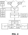
- FIG. 2 illustrates an example hardware configuration 200 of the display system 100 of FIG. 1 in accordance with at least one embodiment of the present disclosure.
- the hardware configuration 200 includes hardware directed to the execution of a VR or AR application (referred to herein as "VR/AR application 202") so as to render VR or AR content representing scenes from current poses of the user's head 104 or the HMD device 102, the VR or AR content comprising a sequence of textures for each eye.
- the hardware configuration 200 further includes EDS hardware directed to the display of the VR or AR content represented by the sequence of textures and which implements the EDS process 120 to as to compensate for interim head rotation between rendered textures as well as interim movement of in-motion virtual objects present in the video represented by the rendered textures.
- the hardware configuration 200 includes an application processor 204, a system memory 206, a sensor hub 208 (which may be a separate component or as functionality implemented by the application processor 204), and an inertial management unit (IMU) 210.
- the HMD device 102 may incorporate image capture for purposes of visual localization or visual telemetry, or for real-time display of imagery captured of the local environment in support of AR functionality.
- the hardware configuration 200 further may include, for example, one or more image sensors 212, 214 and a structured-light or time-of-flight (ToF) depth sensor 216.
- ToF time-of-flight
- the IMU 210 comprises one or more inertial sensors that provide pose information about the HMD device 102 or otherwise facilitate tracking of the pose of the HMD device 102, including, for example, a gyroscope 218, a magnetometer 220, and an accelerometer 222.
- the Sensortec(TM) BMI160 from Bosch Gmbh is an example of a commercially-available implementation of the IMU 210.
- the sensor hub 208 is coupled to the IMU 210, the imaging sensors 212, 214, and the depth sensor 216, and operates to manage the transfer of control signaling and data between the application processor 204 and the IMU 210, the imaging sensors 212, 214, the depth sensor 216, and other sensors of the display system 100.
- the Myriad(TM) 2 vision processing unit (VPU) from Movidius Ltd. is an example of a commercially-available implementation of the sensor hub 208.
- the application processor 204 comprises one or more central processing units (CPUs), graphics processing units (GPUs), or a combination of one or more CPUs and one or more GPUs.
- the Qualcomm(TM) 810 MSM8994 system-on-a-chip (SoC) from Qualcomm Incorporated is an example of a commercially-available implementation of the application processor 204.
- the hardware configuration 200 further includes a compositor 224, the left-eye display 112, and the right-eye display 114.
- the compositor 224 is a device that may be implemented as, for example, an ASIC, programmable logic, as one or more GPUs executing software that manipulates the one or more GPUs to provide the described functionality, or a combination thereof.
- the hardware configuration 200 further includes a left display controller 228 for driving the left eye display 112 and a right display controller 230 for driving the right eye display 114, and which are illustrated as part of the compositor 224.
- the compositor 224 further may include a deep frame buffer 232 for storing one or more textures for each of the left eye display pipeline and right eye display pipeline, as well the depth fields and velocity fields associated therewith, as described herein.
- the application processor 204 executes the VR/AR application 202 (stored in, for example, the system memory 206) to provide VR/AR functionality for a user.
- the VR/AR application 202 manipulates the application processor 204 or associated processor to render a sequence of textures (e.g., input textures 122, FIG. 1 ) for each eye at a particular render rate.
- Each texture contains visual content that may be entirely computer generated, visual content that is a combination of captured imagery (via the imaging sensors 212, 214) and a computer-generated overlay, or a computer-generated overlay displayed over a transparent display panel or window into the local environment.
- the visual content of each texture represents a scene from a corresponding pose of the user's head (or pose of the HMD device 102) at the time that the texture is determined.
- the application processor 204 obtains the current samples from the gyroscope 218, the magnetometer 220, and the accelerometer 222 of the IMU 210 and determines the current pose of the user's head from these inertial sensor readings.
- the application processor 204 may use the information from one or more imaging sensors or depth sensors to determine, verify, or revise the current pose and rotation using one or more visual telemetry or simultaneous localization and mapping (SLAM) techniques.
- SLAM simultaneous localization and mapping
- the application processor 204 renders a pair of input textures that together represent the stereoscopic view of the scene from the determined head orientation and rotation.
- the pair of rendered input textures is then stored in the deep frame buffer 232, which may be part of the system memory 206 or a separate graphics memory.
- the compositor 224 operates to generate display textures (e.g., display texture 140, FIG. 1 ) based on rendered textures and drive the displays 112, 114 based on the generated display textures.
- the compositor 224 implements the EDS process 120 described herein to determine per-pixel net velocities from the per-pixel velocities present in the input textures and the current motion of the HMD device 102 and modify the pair of input textures to reflect these per-pixel net velocities so as to generate a pair of display textures that are more closely aligned with the net motion between the motion of the user's head 104 and the movement of the virtual objects represented in the imagery at the time that the display textures are displayed at the displays 112, 114.
- FIG. 3 illustrates an example implementation of the compositor 224 in accordance with at least one embodiment of the present disclosure.
- the compositor 224 includes the deep frame buffer 232, a motion analysis module 302, a sensor integrator module 304, a transform module 306, a velocity field combination module 314, an advection module 310, and a disocclusion module 312.
- the modules 302, 304, 306, 314, 310, and 312 each may be implemented as part of an ASIC or programmable logic, as one or more processors executing corresponding software, or a combination thereof. The operations of these components are described in greater detail with reference to FIG. 4 .
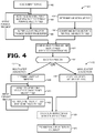
- FIG. 4 illustrates an example method 400 implementing the EDS process 120 of FIG. 1 in the context of the HMD device 102 of FIG. 1 and the hardware configuration 200 of FIGs. 2 and 3 .
- the method 400 initiates at block 402 with the VR/AR application 202 triggering the rendering of an input texture 322 ( FIG. 3 ) based on the current or anticipated pose of the HMD device 102.
- the input texture 322 includes color information (color field 323) for each pixel of a picture or frame, and in the event that multiple fragments are tracked, color information for each fragment associated with the pixel.
- the input texture 322 further may include a depth field 324 (also known as a "depth buffer”) that stores a depth value or depth order for each of some or all of the fragments represented by a pixel.
- a depth field 324 also known as a "depth buffer”
- the motion analysis module 302 analyzes the input texture 322 and one or more preceding input textures (in display order) to determine the per-pixel velocity Vp for each pixel based on the motion of one or more objects represented in the progression from the one or more preceding input textures and the current input texture 322. Any of a variety of motion analysis processes may be utilized.
- the motion analysis module 302 may employ any of a variety of optical flow algorithms to determine the per-pixel velocity, such as optical flow algorithm based one or more of the Lucas-Kanade method, the Buxton-Buxton method, the Black-Jepson method, and the like.
- the pixel velocity Vp may comprise a 2D velocity (e.g., speed and direction in the x-y plane constituting the screen space), a 3D velocity (e.g., speed and direction in the x-y-z world space), or a 3D velocity in addition to rotational velocity around one or more of the three positional axes.
- a 2D velocity e.g., speed and direction in the x-y plane constituting the screen space
- 3D velocity e.g., speed and direction in the x-y-z world space
- 3D velocity in addition to rotational velocity around one or more of the three positional axes.
- the motion analysis module 302 buffers the per-pixel velocities Vp for the pixels constituting the input texture 322 as a pixel velocity field 328 (one embodiment of the pixel velocity field 128, FIG. 1 ) in the deep frame buffer 232 in association with the color field 323 for the input texture 322.
- some or all of the pixels may be associated with multiple fragments, in which case the process of blocks 404 and 406 is repeated for each fragment, resulting in a pixel velocity VP being stored in the pixel velocity field 328 for each fragment represented by a corresponding pixel, and with each pixel velocity VP for a given pixel being stored in depth order in the corresponding entry of the pixel velocity field 328.
- the compositor 224 determines the HMD motion vector MV HMD representing one or both of the instantaneous motion or predicted motion of the HMD device 102.
- the sensor integrator module 304 continually receives sensor samples 331 from one or more of the sensors of the IMU 210 and buffers the sensor samples 331 in a sliding window buffer (not shown).
- the sensor integrator module 304 operates to determine a transformation matrix, or quaternion plus motion vector pair, or other representation of the current motion vector MV HMD , such as through forward integration of some or all of the sensor samples 331 in the sliding window buffer.
- this motion vector MV HMD may represent a motion vector representing a linear velocity of the HMD device 102 along one or more axes, a rotational velocity of the HMD device 102 along one or more axes, or a combination of linear velocity and rotational velocity (e.g., a 6DoF motion vector).
- the transform module 306 transforms the HMD motion vector MV HMD to a per-pixel velocity representation Vh and stores the resulting per-pixel HMD velocities Vh in a HMD velocity field 330 (one embodiment of the HMD velocity field 132, FIG. 1 ).
- the transform module 306 may implement this conversion via application of a virtual-world-space-to-screen-space transform that converts the HMD motion vector MV HMD from the virtual world space coordinate system to the screen space coordinate system.
- this transform may be implemented as a homography transform, although this approach would be only an approximation that assumes the scene is at uniform depth.
- a more accurate (and more computationally expensive) transformation includes accounting for the depth of every fragment (essentially treating each fragment as a 3D point), and subtracting the HMD pose velocity vector from the per fragment velocity vector (assuming both are in virtual world space) to get a HMD-relative fragment velocity vector that could then be transformed into a screen space velocity vector.
- This approach thus adds the velocities in virtual world space and then transforms to screen space; in a different approach, the velocities could be transformed to screen space first and then add the velocities in screen space.
- the velocity field combination module 314 combines the two velocity fields 328, 330 to generate a net velocity field 332 (one embodiment of net velocity field 136, FIG. 1 ), which may be stored in the deep frame buffer 232 or other storage component.
- this combination involves summing, for each pixel, the pixel velocity Vp from the pixel velocity field 328 with the HMD velocity Vh for that same pixel position from the HMD velocity field 330 to generate a corresponding net pixel velocity Vnet for that pixel position.
- Vnet[P, F] Vp[P, F] + Vh[P] for the fragment F at pixel position P).
- the advection module 310 performs an implementation of the texture advection process 138 to modify the input texture 322 to reflect the per-pixel net velocities Vnet in the net velocity field 332 for a corresponding time span.
- the advection process 138 may be implemented in one of two ways: a single-step advection process 415 or a multi-step advection process 417.
- the single-step advection process 415 represents a less accurate, but computationally less complex manner of representing the net motion.
- the multi-step advection process represents a more accurate, but more computationally complex process.
- the single-step advection process 415 is represented by block 416, whereupon the advection module 310 advects the color information (color field 323) of the input texture 322 using the net pixel velocities Vnet of the net velocity field 332 using any of a variety of well-known particle/velocity advection processes, such as an advection process based on the Lagrangian-Eulerian texture advection method or based on a Semi-Lagrangian method. In the event that multiple fragments are represented by some or all of the pixel positions, this advection process is repeated for each depth/fragment.
- the depth information may likewise be advected based on the net velocity field 332 to maintain the correlation between the pixels and the depth information.
- the timespan or timestep represented in the advection process may be, or be based on, the expected duration between the rendering of the input texture 322 and the scan out or display of a corresponding display texture 334 (one embodiment of display texture 140, FIG. 1 ) generated from the input texture 322 as a result of the EDS process described herein.
- the display image then may be processed to reproject the texture into screen space to generate a final image to be displayed via the corresponding display controller
- the multi-step advection process 417 initiates at block 418 with the determination of the number of timesteps, or iterations, to be implemented in current instance of the multi-step advection process.
- the number of timesteps is determined based on the ratio of the render rate X of the input textures to the calculation rate Y of the net velocity field 332. To illustrate, if the render rate is 60 fps and a new net velocity field 332 is determined 120 times per second, the multi-step advection process would have effectively 120 timesteps per second. If the render rate is 60 fps and a new net velocity field 332 is determined at 240 times per second, the multi-step advection process would have 240 timesteps per second.
- a first iteration of the process is initiated at block 420 whereupon the advection module 310 advects the color field 323 of the current input texture 322 with the net velocity field 332 to generate a display texture 334 for the current iteration (which is then displayed as described below). Assuming there is more than one iteration, next at the second iteration of block 422 the advection module 310 advects the net velocity field 332 with itself (that is, self-advects the net velocity field 332) to generate a modified net velocity field.
- the next input texture 322 is rendered at block 404 and at the second iteration of block 420 the advection module 310 then advects this next input texture 322 with the modified net velocity field to generate a second display texture 334.
- the modified net velocity field is self-advected at a second iteration of block 422 to generate a twice-modified net velocity field.
- the next input texture 322 rendered at a third iteration of block 402 is advected with the twice-modified net velocity field at a third iteration of block 420 to generate a third display texture 334, and so on.
- the disocclusion module 312 may utilize the depth information represented in the depth field 324, the information on the multiple fragments, and any of a variety of well-known disocclusion processes to remove disocclusion errors that may arise as a result of the advection process.
- the disocclusion module 312 or another module may create motion blur to reduce perception issues by blending the display texture 334 with the input texture 322 from which it was generated, and use the resulting blended texture as the display texture.
- Each display texture 334 generated by an iteration of the advection process of block 414 (and which may be disoccluded and/or motion blurred via an iteration of block 424) is then, at block 426, re-projected in screen space to generate a final, or display, image that is provided by the compositor 224 to the corresponding display controller 228, 230 for scan out to the corresponding one of the displays 112, 114.
- certain aspects of the techniques described above may implemented by one or more processors of a processing system executing software.
- the software comprises one or more sets of executable instructions stored or otherwise tangibly embodied on a non-transitory computer readable storage medium.
- the software can include the instructions and certain data that, when executed by the one or more processors, manipulate the one or more processors to perform one or more aspects of the techniques described above.
- the non-transitory computer readable storage medium can include, for example, a magnetic or optical disk storage device, solid state storage devices such as Flash memory, a cache, random access memory (RAM) or other non-volatile memory device or devices, and the like.
- the executable instructions stored on the non-transitory computer readable storage medium may be in source code, assembly language code, object code, or other instruction format that is interpreted or otherwise executable by one or more processors.
- another is defined as at least a second or more.
- the terms “including” and/or “having”, as used herein, are defined as comprising.
- the term “coupled”, as used herein with reference to electro-optical technology, is defined as connected, although not necessarily directly, and not necessarily mechanically.
- the term “program”, as used herein, is defined as a sequence of instructions designed for execution on a computer system.
- a "program”, “computer program”, “application”, or “software” may include a subroutine, a function, a procedure, an object method, an object implementation, an executable application, an applet, a servlet, a source code, an object code, a shared library/dynamic load library and/or other sequence of instructions designed for execution on a computer system.
Landscapes
- Engineering & Computer Science (AREA)
- Physics & Mathematics (AREA)
- Theoretical Computer Science (AREA)
- General Physics & Mathematics (AREA)
- General Engineering & Computer Science (AREA)
- Multimedia (AREA)
- Human Computer Interaction (AREA)
- Signal Processing (AREA)
- Optics & Photonics (AREA)
- Computer Graphics (AREA)
- Software Systems (AREA)
- Computer Hardware Design (AREA)
- Computer Vision & Pattern Recognition (AREA)
- User Interface Of Digital Computer (AREA)
- Processing Or Creating Images (AREA)
- Controls And Circuits For Display Device (AREA)
- Testing, Inspecting, Measuring Of Stereoscopic Televisions And Televisions (AREA)
Claims (16)
- Verfahren in einem System (100) mit einem am Kopf befestigten Anzeigegerät, HMD-Gerät (102), umfassend:Rendern einer ersten Textur (122, 322);Ermitteln eines ersten Geschwindigkeitsfeldes (128, 328) mit einer Pixelgeschwindigkeit für zumindest eine Teilmenge von Pixeln der ersten Textur;Ermitteln eines Bewegungsvektors für das HMD-Gerät;Ermitteln eines zweiten Geschwindigkeitsfeldes (132, 330), umfassend eine pixelbezogene Geschwindigkeitsdarstellung des Bewegungsvektors für das HMD-Gerät;Kombinieren des ersten Geschwindigkeitsfeldes und des zweiten Geschwindigkeitsfeldes, um ein drittes Geschwindigkeitsfeld zu erzeugen (332);Rendern einer zweiten Textur (140, 334) basierend auf der ersten Textur und dem dritten Geschwindigkeitsfeld (332); undBereitstellen der zweiten Textur zur Anzeige auf dem HMD-Gerät.
- Verfahren nach Anspruch 1, wobei das Rendern der zweiten Textur umfasst:
Advektieren von Farbinformationen (323) für Pixel der ersten Textur unter Nutzung des dritten Geschwindigkeitsfeldes, um die zweite Textur zu erzeugen. - Verfahren nach Anspruch 2, wobei das Rendern der zweiten Textur ferner umfasst:
Advektieren von Tiefeninformationen (324) für Pixel der ersten Textur unter Nutzung des dritten Geschwindigkeitsfeldes, um die zweite Textur zu erzeugen. - Verfahren nach Anspruch 2, ferner umfassend:Rendern einer dritten Textur;Rendern einer vierten Textur durch:Selbstadvektieren (422) des dritten Geschwindigkeitsfeldes, um ein viertes Geschwindigkeitsfeld zu erzeugen; undAdvektieren (420) von Farbinformationen für Pixel der dritten Textur unter Nutzung des vierten Geschwindigkeitsfeldes, um die vierte Textur zu erzeugen; undBereitstellen der vierten Textur zur Anzeige auf dem HMD-Gerät.
- Verfahren nach Anspruch 1, wobei das Ermitteln des zweiten Geschwindigkeitsfeldes umfasst:
Anwenden einer virtuelle-Welt-Raum-zu-Bildschirm-Raum-Transformation auf den Bewegungsvektor für das HMD-Gerät, um das zweite Geschwindigkeitsfeld zu erzeugen. - Verfahren nach Anspruch 1, wobei:jedes Pixel zumindest einer Teilmenge von Pixeln der ersten Textur mit einem entsprechenden Satz von zumindest zwei Fragmenten (144, 146) assoziiert ist; unddas Ermitteln des ersten Geschwindigkeitsfeldes ein Ermitteln, für jedes Pixel zumindest der Teilmenge, einer separaten Pixelgeschwindigkeit des Pixels für jedes Fragment des entsprechenden Satzes von zumindest zwei Fragmenten umfasst.
- Verfahren nach Anspruch 1, wobei das Rendern der zweiten Textur ferner umfasst:
Entfernen (424) von Disokklusionsfehlern in der zweiten Textur basierend auf Tiefeninformationen (324) für Pixel der ersten Textur. - Verfahren nach Anspruch 1, wobei das Ermitteln des ersten Geschwindigkeitsfeldes umfasst:
Ermitteln des ersten Geschwindigkeitsfeldes basierend auf einer optischen Flussanalyse einer Sequenz (126) von Texturen, die die erste Textur beinhaltet. - System (100), umfassend:ein am Kopf befestigtes Anzeigegerät, HMD-Gerät (100), umfassend zumindest eine Anzeige (112, 114);zumindest einen Sensor (210) zum Bereitstellen von Poseinformationen für das HMD-Gerät;ein Sensorintegratormodul (304), das mit dem zumindest einen Sensor verbunden ist, wobei das Sensorintegratormodul dazu vorgesehen ist, einen Bewegungsvektor für das HMD-Gerät basierend auf den Poseinformationen zu ermitteln;einen Anwendungsprozessor (204) zum Rendern einer ersten Textur (122, 322) basierend auf einer Pose des HMD-Geräts, die anhand der Poseinformationen ermittelt wird;ein Bewegungsanalysemodul (302) zum Ermitteln eines ersten Geschwindigkeitsfeldes (128, 328) mit einer Pixelgeschwindigkeit für zumindest eine Teilmenge von Pixeln der ersten Textur;ein Transformationsmodul (306) zum Ermitteln eines zweiten Geschwindigkeitsfeldes (132, 330), das eine pixelbezogene Geschwindigkeitsdarstellung des Bewegungsvektors für das HMD-Gerät umfasst;ein Geschwindigkeitsfeld-Kombinationsmodul (314) zum Kombinieren des ersten Geschwindigkeitsfeldes und des zweiten Geschwindigkeitsfeldes, um ein drittes Geschwindigkeitsfeld (136, 332) zu erzeugen; undeinen Compositor (224) zum Rendern einer zweiten Textur (140, 334) basierend auf der ersten Textur und dem dritten Geschwindigkeitsfeld (136, 332), und zum Bereitstellen der zweiten Textur für die Anzeige des HMD-Geräts.
- System nach Anspruch 9, wobei der Compositor umfasst:
ein Advektionsmodul (310) zum Advektieren von Farbinformationen (323) für Pixel der ersten Textur unter Nutzung des dritten Geschwindigkeitsfeldes, um die zweite Textur zu erzeugen. - System nach Anspruch 10, wobei:
das Advektionsmodul ferner dazu vorgesehen ist, Tiefeninformationen (324) für Pixel der ersten Textur unter Nutzung des dritten Geschwindigkeitsfeldes zu advektieren, um die zweite Textur erzeugen. - System nach Anspruch 10, wobei:der Anwendungsprozessor ferner dazu vorgesehen ist, eine dritte Textur zu rendern; undder Compositor ferner dazu vorgesehen ist, eine vierte Textur zu rendern durch:Selbstadvektieren des dritten Geschwindigkeitsfeldes, um ein viertes Geschwindigkeitsfeld zu erzeugen; undAdvektieren von Farbinformationen für Pixel der dritten Textur unter Nutzung des vierten Geschwindigkeitsfeldes, um die vierte Textur zu erzeugen; undwobei der Compositor dazu vorgesehen ist, die vierte Textur zur Anzeige auf dem HMD-Gerät bereitzustellen.
- System nach Anspruch 9, wobei:
das Transformationsmodul dazu vorgesehen ist, das zweite Geschwindigkeitsfeld durch Anwenden einer Homographietransformation auf den Bewegungsvektor für das HMD-Gerät zu ermitteln, um das zweite Geschwindigkeitsfeld zu erzeugen. - System nach Anspruch 9, wobei:jedes Pixel zumindest einer Teilmenge von Pixeln der ersten Textur mit einem entsprechenden Satz von zumindest zwei Fragmenten (144, 146) assoziiert ist; unddas Bewegungsanalysemodul dazu vorgesehen ist, das erste Geschwindigkeitsfeld durch Ermitteln, für jedes Pixel zumindest der Teilmenge von Pixeln, einer separaten Pixelgeschwindigkeit des Pixels für jedes Fragment des entsprechenden Satzes von zumindest zwei Fragmenten zu ermitteln.
- System nach Anspruch 9, ferner umfassend:
ein Disokklusionsmodul (312) zum Entfernen von Disokklusionsfehlern in der zweiten Textur basierend auf Tiefeninformationen (324) für Pixel der ersten Textur. - System nach Anspruch 9, wobei:
das Bewegungsanalysemodul dazu vorgesehen ist, das erste Geschwindigkeitsfeld basierend auf einer optischen Flussanalyse einer Sequenz (126) von Texturen, die die erste Textur beinhaltet, zu ermitteln.
Applications Claiming Priority (2)
| Application Number | Priority Date | Filing Date | Title |
|---|---|---|---|
| US14/946,983 US10026212B2 (en) | 2015-11-20 | 2015-11-20 | Electronic display stabilization using pixel velocities |
| PCT/US2016/055528 WO2017087083A1 (en) | 2015-11-20 | 2016-10-05 | Electronic display stabilization using pixel velocities |
Publications (2)
| Publication Number | Publication Date |
|---|---|
| EP3377960A1 EP3377960A1 (de) | 2018-09-26 |
| EP3377960B1 true EP3377960B1 (de) | 2019-10-02 |
Family
ID=57208364
Family Applications (1)
| Application Number | Title | Priority Date | Filing Date |
|---|---|---|---|
| EP16787960.0A Active EP3377960B1 (de) | 2015-11-20 | 2016-10-05 | Stabilisierung einer elektronischen anzeige durch verwendung der geschwindigkeit von pixeln |
Country Status (10)
| Country | Link |
|---|---|
| US (1) | US10026212B2 (de) |
| EP (1) | EP3377960B1 (de) |
| JP (1) | JP6514826B2 (de) |
| KR (1) | KR102135808B1 (de) |
| CN (1) | CN108139807B (de) |
| AU (1) | AU2016357105B2 (de) |
| CA (1) | CA2999182C (de) |
| DE (1) | DE112016005343T5 (de) |
| GB (1) | GB2557525B (de) |
| WO (1) | WO2017087083A1 (de) |
Families Citing this family (38)
| Publication number | Priority date | Publication date | Assignee | Title |
|---|---|---|---|---|
| US10838207B2 (en) | 2015-03-05 | 2020-11-17 | Magic Leap, Inc. | Systems and methods for augmented reality |
| CN112764536B (zh) | 2015-03-05 | 2025-04-01 | 奇跃公司 | 用于增强现实的系统和方法 |
| US10962780B2 (en) * | 2015-10-26 | 2021-03-30 | Microsoft Technology Licensing, Llc | Remote rendering for virtual images |
| JP2018536244A (ja) | 2015-12-04 | 2018-12-06 | マジック リープ, インコーポレイテッドMagic Leap,Inc. | 再位置特定システムおよび方法 |
| CN105807915A (zh) * | 2016-02-24 | 2016-07-27 | 北京小鸟看看科技有限公司 | 虚拟鼠标的控制方法、控制装置以及头戴显示设备 |
| US11430070B1 (en) | 2017-07-31 | 2022-08-30 | Block, Inc. | Intelligent application of reserves to transactions |
| IL264489B (en) | 2016-08-02 | 2022-07-01 | Magic Leap Inc | Virtual and augmented reality systems at a fixed distance and methods |
| US20180203504A1 (en) * | 2017-01-16 | 2018-07-19 | Htc Corporation | Movement tracking method and movement tracking system |
| US10812936B2 (en) | 2017-01-23 | 2020-10-20 | Magic Leap, Inc. | Localization determination for mixed reality systems |
| IL303275B2 (en) | 2017-03-17 | 2024-08-01 | Magic Leap Inc | A mixed reality system with the assembly of multi-source virtual content and a method for creating virtual content using it |
| KR102366781B1 (ko) | 2017-03-17 | 2022-02-22 | 매직 립, 인코포레이티드 | 컬러 가상 콘텐츠 와핑을 갖는 혼합 현실 시스템 및 이를 사용하여 가상 콘텐츠를 생성하는 방법 |
| US10769752B2 (en) | 2017-03-17 | 2020-09-08 | Magic Leap, Inc. | Mixed reality system with virtual content warping and method of generating virtual content using same |
| US20180329465A1 (en) * | 2017-05-11 | 2018-11-15 | Qualcomm Incorporated | System and method for intelligent adjustment of an immersive multimedia workload in a portable computing device |
| US10914957B1 (en) | 2017-05-30 | 2021-02-09 | Apple Inc. | Video compression methods and apparatus |
| IL253432A0 (en) * | 2017-07-11 | 2017-09-28 | Elbit Systems Ltd | System and method for correcting a rolling display effect |
| WO2019012522A1 (en) | 2017-07-11 | 2019-01-17 | Elbit Systems Ltd. | SYSTEM AND METHOD FOR CORRECTING A RUNNING DISPLAY EFFECT |
| US10762691B2 (en) | 2017-09-08 | 2020-09-01 | Microsoft Technology Licensing, Llc | Techniques for compensating variable display device latency in image display |
| TWI669683B (zh) * | 2017-09-12 | 2019-08-21 | 宏達國際電子股份有限公司 | 三維影像重建方法、裝置及其非暫態電腦可讀取儲存媒體 |
| LU100596B1 (fr) * | 2017-12-27 | 2019-06-28 | Starbreeze Ip Lux Ii S A R L | Procede et dispositif d'affichage a faible latence et haut taux de rafraichissement pour afficheurs de realite mixte a haute definition |
| CN108988974B (zh) * | 2018-06-19 | 2020-04-07 | 远形时空科技(北京)有限公司 | 时间延时的测量方法、装置和对电子设备时间同步的系统 |
| EP3827299B1 (de) | 2018-07-23 | 2025-07-09 | Magic Leap, Inc. | System der gemischten realität mit virtueller inhaltsverzerrung und verfahren zur erzeugung eines virtuellen inhalts damit |
| JP7210180B2 (ja) * | 2018-07-25 | 2023-01-23 | キヤノン株式会社 | 画像処理装置、画像表示装置、画像処理方法、及びプログラム |
| US10733783B2 (en) * | 2018-10-09 | 2020-08-04 | Valve Corporation | Motion smoothing for re-projected frames |
| US11170577B2 (en) * | 2018-10-30 | 2021-11-09 | Facebook Technologies, Llc | Generating and modifying representations of objects in an augmented-reality or virtual-reality scene |
| US11308681B1 (en) * | 2018-11-02 | 2022-04-19 | Facebook Technologies, Llc. | Display engine for post-rendering processing |
| CN109859258B (zh) * | 2019-02-02 | 2021-02-12 | 网易(杭州)网络有限公司 | 界面处理方法及装置、电子设备 |
| US11430141B2 (en) * | 2019-11-04 | 2022-08-30 | Facebook Technologies, Llc | Artificial reality system using a multisurface display protocol to communicate surface data |
| US12148120B2 (en) * | 2019-12-18 | 2024-11-19 | Ati Technologies Ulc | Frame reprojection for virtual reality and augmented reality |
| US11363247B2 (en) * | 2020-02-14 | 2022-06-14 | Valve Corporation | Motion smoothing in a distributed system |
| KR102909089B1 (ko) | 2020-07-13 | 2026-01-13 | 삼성전자주식회사 | 혼합현실/증강현실을 지원하는 통신 시스템에서 3차원 미디어 데이터에 대해 지연 시간 보상 포즈 예측을 사용하는 렌더링을 수행하는 방법 및 장치 |
| WO2022064576A1 (ja) * | 2020-09-23 | 2022-03-31 | 株式会社ソニー・インタラクティブエンタテインメント | 位置情報取得装置、ヘッドマウントディスプレイ、および位置情報取得方法 |
| CN112156467B (zh) * | 2020-10-15 | 2024-07-16 | 网易(杭州)网络有限公司 | 虚拟相机的控制方法、系统、存储介质与终端设备 |
| CN115733938B (zh) * | 2021-08-31 | 2025-02-25 | 北京字跳网络技术有限公司 | 视频处理方法、装置、设备及存储介质 |
| DE102021211162A1 (de) * | 2021-10-04 | 2023-04-06 | Gritworld GmbH | Verfahren und System zur Visualisierung und Simulation von Strömungsphänomenen |
| US12327501B2 (en) * | 2022-12-22 | 2025-06-10 | Microsoft Technology Licensing, Llc | Systems and methods for facilitating display misalignment correction based on vergence angle |
| US12548481B2 (en) * | 2023-02-17 | 2026-02-10 | Meta Platforms Technologies, Llc | Virtual reality and augmented reality display system for near-eye display devices |
| US12627787B2 (en) | 2023-04-03 | 2026-05-12 | Microsoft Technology Licensing, Llc | Distance-based vertical misalignment correction |
| GB2635221A (en) * | 2023-11-03 | 2025-05-07 | Sony Interactive Entertainment Inc | Image processing method and system |
Family Cites Families (21)
| Publication number | Priority date | Publication date | Assignee | Title |
|---|---|---|---|---|
| US5627905A (en) | 1994-12-12 | 1997-05-06 | Lockheed Martin Tactical Defense Systems | Optical flow detection system |
| US6480615B1 (en) * | 1999-06-15 | 2002-11-12 | University Of Washington | Motion estimation within a sequence of data frames using optical flow with adaptive gradients |
| US7724258B2 (en) | 2004-06-30 | 2010-05-25 | Purdue Research Foundation | Computer modeling and animation of natural phenomena |
| US20060244757A1 (en) | 2004-07-26 | 2006-11-02 | The Board Of Trustees Of The University Of Illinois | Methods and systems for image modification |
| US7643034B2 (en) | 2006-06-30 | 2010-01-05 | Microsoft Corporation | Synthesis of advecting texture using adaptive regeneration |
| US8773448B2 (en) | 2010-04-09 | 2014-07-08 | Intel Corporation | List texture |
| US8823746B2 (en) | 2010-10-19 | 2014-09-02 | Apple Inc. | System and method for motion blur using velocity vectors |
| US9348141B2 (en) * | 2010-10-27 | 2016-05-24 | Microsoft Technology Licensing, Llc | Low-latency fusing of virtual and real content |
| US8860570B2 (en) | 2011-02-03 | 2014-10-14 | SenseTech, LLC | Portable wireless personal head impact reporting system |
| CN102958009B (zh) * | 2011-08-26 | 2017-09-08 | 中兴通讯股份有限公司 | 增强现实信息的传输方法和移动增强现实服务器 |
| CN103810356A (zh) * | 2012-11-05 | 2014-05-21 | 大连力天科技有限公司 | 基于增强现实技术及lbs功能的移动终端系统 |
| US20140176591A1 (en) * | 2012-12-26 | 2014-06-26 | Georg Klein | Low-latency fusing of color image data |
| US9076258B2 (en) | 2013-03-14 | 2015-07-07 | Pixar | Stylizing animation by example |
| GB201310367D0 (en) * | 2013-06-11 | 2013-07-24 | Sony Comp Entertainment Europe | Head-mountable apparatus and systems |
| JP6353214B2 (ja) * | 2013-11-11 | 2018-07-04 | 株式会社ソニー・インタラクティブエンタテインメント | 画像生成装置および画像生成方法 |
| US9311690B2 (en) * | 2014-03-11 | 2016-04-12 | Adobe Systems Incorporated | Video denoising using optical flow |
| US9652893B2 (en) * | 2014-04-29 | 2017-05-16 | Microsoft Technology Licensing, Llc | Stabilization plane determination based on gaze location |
| CN104156998A (zh) * | 2014-08-08 | 2014-11-19 | 深圳中科呼图信息技术有限公司 | 一种基于图片虚拟内容融合真实场景的实现方法及系统 |
| CN104463191A (zh) * | 2014-10-30 | 2015-03-25 | 华南理工大学 | 一种基于注意机制的机器人视觉处理方法 |
| US9824498B2 (en) | 2014-12-30 | 2017-11-21 | Sony Interactive Entertainment Inc. | Scanning display system in head-mounted display for virtual reality |
| CN104571532B (zh) * | 2015-02-04 | 2018-01-30 | 网易有道信息技术(北京)有限公司 | 一种实现增强现实或虚拟现实的方法及装置 |
-
2015
- 2015-11-20 US US14/946,983 patent/US10026212B2/en active Active
-
2016
- 2016-10-05 KR KR1020187010123A patent/KR102135808B1/ko active Active
- 2016-10-05 DE DE112016005343.6T patent/DE112016005343T5/de not_active Withdrawn
- 2016-10-05 GB GB1804600.3A patent/GB2557525B/en not_active Expired - Fee Related
- 2016-10-05 JP JP2018513848A patent/JP6514826B2/ja active Active
- 2016-10-05 AU AU2016357105A patent/AU2016357105B2/en active Active
- 2016-10-05 WO PCT/US2016/055528 patent/WO2017087083A1/en not_active Ceased
- 2016-10-05 CN CN201680059892.XA patent/CN108139807B/zh active Active
- 2016-10-05 CA CA2999182A patent/CA2999182C/en active Active
- 2016-10-05 EP EP16787960.0A patent/EP3377960B1/de active Active
Non-Patent Citations (1)
| Title |
|---|
| None * |
Also Published As
| Publication number | Publication date |
|---|---|
| WO2017087083A1 (en) | 2017-05-26 |
| JP6514826B2 (ja) | 2019-05-15 |
| DE112016005343T5 (de) | 2018-08-02 |
| AU2016357105B2 (en) | 2019-02-21 |
| GB2557525A (en) | 2018-06-20 |
| KR20180051607A (ko) | 2018-05-16 |
| CA2999182C (en) | 2020-09-22 |
| CN108139807A (zh) | 2018-06-08 |
| US20170148206A1 (en) | 2017-05-25 |
| AU2016357105A1 (en) | 2018-04-19 |
| JP2019506015A (ja) | 2019-02-28 |
| US10026212B2 (en) | 2018-07-17 |
| CA2999182A1 (en) | 2017-05-26 |
| KR102135808B1 (ko) | 2020-07-20 |
| EP3377960A1 (de) | 2018-09-26 |
| GB201804600D0 (en) | 2018-05-09 |
| CN108139807B (zh) | 2021-03-23 |
| GB2557525B (en) | 2021-06-09 |
Similar Documents
| Publication | Publication Date | Title |
|---|---|---|
| CA2999182C (en) | Electronic display stabilization using pixel velocities | |
| US10102666B2 (en) | Electronic display stabilization for head mounted display | |
| US10419747B2 (en) | System and methods for performing electronic display stabilization via retained lightfield rendering | |
| US10026233B2 (en) | Efficient orientation estimation system using magnetic, angular rate, and gravity sensors | |
| US11024082B2 (en) | Pass-through display of captured imagery | |
| US9240069B1 (en) | Low-latency virtual reality display system | |
| US10628994B2 (en) | Reducing visually induced motion sickness in head mounted display systems | |
| Mori et al. | A survey of diminished reality: Techniques for visually concealing, eliminating, and seeing through real objects | |
| US10089790B2 (en) | Predictive virtual reality display system with post rendering correction | |
| EP4165596B1 (de) | Optische ausrichtung mit zwei systemen für getrennte kameras | |
| KR20180099703A (ko) | 적응형 초점면을 갖는 가상 현실을 렌더링하기 위한 구성 | |
| WO2018064287A1 (en) | Predictive virtual reality display system with post rendering correction | |
| US20240404179A1 (en) | Method and Device for Refining a Depth Map | |
| US20220066546A1 (en) | Manipulator-based image reprojection |
Legal Events
| Date | Code | Title | Description |
|---|---|---|---|
| STAA | Information on the status of an ep patent application or granted ep patent |
Free format text: STATUS: UNKNOWN |
|
| STAA | Information on the status of an ep patent application or granted ep patent |
Free format text: STATUS: THE INTERNATIONAL PUBLICATION HAS BEEN MADE |
|
| PUAI | Public reference made under article 153(3) epc to a published international application that has entered the european phase |
Free format text: ORIGINAL CODE: 0009012 |
|
| STAA | Information on the status of an ep patent application or granted ep patent |
Free format text: STATUS: REQUEST FOR EXAMINATION WAS MADE |
|
| 17P | Request for examination filed |
Effective date: 20180322 |
|
| AK | Designated contracting states |
Kind code of ref document: A1 Designated state(s): AL AT BE BG CH CY CZ DE DK EE ES FI FR GB GR HR HU IE IS IT LI LT LU LV MC MK MT NL NO PL PT RO RS SE SI SK SM TR |
|
| AX | Request for extension of the european patent |
Extension state: BA ME |
|
| RIC1 | Information provided on ipc code assigned before grant |
Ipc: G02B 27/00 20060101ALI20170613BHEP Ipc: G02B 27/01 20060101ALI20170613BHEP Ipc: G06F 3/01 20060101AFI20170613BHEP Ipc: G06F 3/0346 20130101ALI20170613BHEP Ipc: G06F 3/038 20130101ALI20170613BHEP Ipc: H04N 13/04 20060101ALI20170613BHEP |
|
| DAV | Request for validation of the european patent (deleted) | ||
| DAX | Request for extension of the european patent (deleted) | ||
| GRAP | Despatch of communication of intention to grant a patent |
Free format text: ORIGINAL CODE: EPIDOSNIGR1 |
|
| STAA | Information on the status of an ep patent application or granted ep patent |
Free format text: STATUS: GRANT OF PATENT IS INTENDED |
|
| RIC1 | Information provided on ipc code assigned before grant |
Ipc: G06F 3/01 20060101AFI20190409BHEP Ipc: G06T 7/285 20170101ALI20190409BHEP Ipc: G06T 7/90 20170101ALI20190409BHEP Ipc: G06T 19/00 20110101ALI20190409BHEP Ipc: G02B 27/01 20060101ALI20190409BHEP Ipc: H04N 13/344 20180101ALI20190409BHEP Ipc: G06F 3/038 20130101ALI20190409BHEP Ipc: G06F 3/0346 20130101ALI20190409BHEP Ipc: G06T 15/04 20110101ALI20190409BHEP Ipc: G02B 27/00 20060101ALI20190409BHEP Ipc: H04N 13/376 20180101ALI20190409BHEP |
|
| INTG | Intention to grant announced |
Effective date: 20190510 |
|
| GRAS | Grant fee paid |
Free format text: ORIGINAL CODE: EPIDOSNIGR3 |
|
| GRAA | (expected) grant |
Free format text: ORIGINAL CODE: 0009210 |
|
| STAA | Information on the status of an ep patent application or granted ep patent |
Free format text: STATUS: THE PATENT HAS BEEN GRANTED |
|
| AK | Designated contracting states |
Kind code of ref document: B1 Designated state(s): AL AT BE BG CH CY CZ DE DK EE ES FI FR GB GR HR HU IE IS IT LI LT LU LV MC MK MT NL NO PL PT RO RS SE SI SK SM TR |
|
| REG | Reference to a national code |
Ref country code: GB Ref legal event code: FG4D |
|
| REG | Reference to a national code |
Ref country code: CH Ref legal event code: EP Ref country code: AT Ref legal event code: REF Ref document number: 1186913 Country of ref document: AT Kind code of ref document: T Effective date: 20191015 |
|
| REG | Reference to a national code |
Ref country code: DE Ref legal event code: R096 Ref document number: 602016021798 Country of ref document: DE |
|
| REG | Reference to a national code |
Ref country code: IE Ref legal event code: FG4D |
|
| REG | Reference to a national code |
Ref country code: NL Ref legal event code: FP |
|
| REG | Reference to a national code |
Ref country code: LT Ref legal event code: MG4D |
|
| REG | Reference to a national code |
Ref country code: AT Ref legal event code: MK05 Ref document number: 1186913 Country of ref document: AT Kind code of ref document: T Effective date: 20191002 |
|
| PG25 | Lapsed in a contracting state [announced via postgrant information from national office to epo] |
Ref country code: NO Free format text: LAPSE BECAUSE OF FAILURE TO SUBMIT A TRANSLATION OF THE DESCRIPTION OR TO PAY THE FEE WITHIN THE PRESCRIBED TIME-LIMIT Effective date: 20200102 Ref country code: GR Free format text: LAPSE BECAUSE OF FAILURE TO SUBMIT A TRANSLATION OF THE DESCRIPTION OR TO PAY THE FEE WITHIN THE PRESCRIBED TIME-LIMIT Effective date: 20200103 Ref country code: PL Free format text: LAPSE BECAUSE OF FAILURE TO SUBMIT A TRANSLATION OF THE DESCRIPTION OR TO PAY THE FEE WITHIN THE PRESCRIBED TIME-LIMIT Effective date: 20191002 Ref country code: SE Free format text: LAPSE BECAUSE OF FAILURE TO SUBMIT A TRANSLATION OF THE DESCRIPTION OR TO PAY THE FEE WITHIN THE PRESCRIBED TIME-LIMIT Effective date: 20191002 Ref country code: LV Free format text: LAPSE BECAUSE OF FAILURE TO SUBMIT A TRANSLATION OF THE DESCRIPTION OR TO PAY THE FEE WITHIN THE PRESCRIBED TIME-LIMIT Effective date: 20191002 Ref country code: FI Free format text: LAPSE BECAUSE OF FAILURE TO SUBMIT A TRANSLATION OF THE DESCRIPTION OR TO PAY THE FEE WITHIN THE PRESCRIBED TIME-LIMIT Effective date: 20191002 Ref country code: PT Free format text: LAPSE BECAUSE OF FAILURE TO SUBMIT A TRANSLATION OF THE DESCRIPTION OR TO PAY THE FEE WITHIN THE PRESCRIBED TIME-LIMIT Effective date: 20200203 Ref country code: BG Free format text: LAPSE BECAUSE OF FAILURE TO SUBMIT A TRANSLATION OF THE DESCRIPTION OR TO PAY THE FEE WITHIN THE PRESCRIBED TIME-LIMIT Effective date: 20200102 Ref country code: AT Free format text: LAPSE BECAUSE OF FAILURE TO SUBMIT A TRANSLATION OF THE DESCRIPTION OR TO PAY THE FEE WITHIN THE PRESCRIBED TIME-LIMIT Effective date: 20191002 Ref country code: ES Free format text: LAPSE BECAUSE OF FAILURE TO SUBMIT A TRANSLATION OF THE DESCRIPTION OR TO PAY THE FEE WITHIN THE PRESCRIBED TIME-LIMIT Effective date: 20191002 Ref country code: LT Free format text: LAPSE BECAUSE OF FAILURE TO SUBMIT A TRANSLATION OF THE DESCRIPTION OR TO PAY THE FEE WITHIN THE PRESCRIBED TIME-LIMIT Effective date: 20191002 |
|
| PG25 | Lapsed in a contracting state [announced via postgrant information from national office to epo] |
Ref country code: IS Free format text: LAPSE BECAUSE OF FAILURE TO SUBMIT A TRANSLATION OF THE DESCRIPTION OR TO PAY THE FEE WITHIN THE PRESCRIBED TIME-LIMIT Effective date: 20200224 Ref country code: CZ Free format text: LAPSE BECAUSE OF FAILURE TO SUBMIT A TRANSLATION OF THE DESCRIPTION OR TO PAY THE FEE WITHIN THE PRESCRIBED TIME-LIMIT Effective date: 20191002 Ref country code: HR Free format text: LAPSE BECAUSE OF FAILURE TO SUBMIT A TRANSLATION OF THE DESCRIPTION OR TO PAY THE FEE WITHIN THE PRESCRIBED TIME-LIMIT Effective date: 20191002 Ref country code: RS Free format text: LAPSE BECAUSE OF FAILURE TO SUBMIT A TRANSLATION OF THE DESCRIPTION OR TO PAY THE FEE WITHIN THE PRESCRIBED TIME-LIMIT Effective date: 20191002 |
|
| REG | Reference to a national code |
Ref country code: CH Ref legal event code: PL |
|
| PG25 | Lapsed in a contracting state [announced via postgrant information from national office to epo] |
Ref country code: AL Free format text: LAPSE BECAUSE OF FAILURE TO SUBMIT A TRANSLATION OF THE DESCRIPTION OR TO PAY THE FEE WITHIN THE PRESCRIBED TIME-LIMIT Effective date: 20191002 |
|
| REG | Reference to a national code |
Ref country code: DE Ref legal event code: R097 Ref document number: 602016021798 Country of ref document: DE |
|
| PG2D | Information on lapse in contracting state deleted |
Ref country code: IS |
|
| PG25 | Lapsed in a contracting state [announced via postgrant information from national office to epo] |
Ref country code: MC Free format text: LAPSE BECAUSE OF FAILURE TO SUBMIT A TRANSLATION OF THE DESCRIPTION OR TO PAY THE FEE WITHIN THE PRESCRIBED TIME-LIMIT Effective date: 20191002 Ref country code: CH Free format text: LAPSE BECAUSE OF NON-PAYMENT OF DUE FEES Effective date: 20191031 Ref country code: DK Free format text: LAPSE BECAUSE OF FAILURE TO SUBMIT A TRANSLATION OF THE DESCRIPTION OR TO PAY THE FEE WITHIN THE PRESCRIBED TIME-LIMIT Effective date: 20191002 Ref country code: EE Free format text: LAPSE BECAUSE OF FAILURE TO SUBMIT A TRANSLATION OF THE DESCRIPTION OR TO PAY THE FEE WITHIN THE PRESCRIBED TIME-LIMIT Effective date: 20191002 Ref country code: RO Free format text: LAPSE BECAUSE OF FAILURE TO SUBMIT A TRANSLATION OF THE DESCRIPTION OR TO PAY THE FEE WITHIN THE PRESCRIBED TIME-LIMIT Effective date: 20191002 Ref country code: LI Free format text: LAPSE BECAUSE OF NON-PAYMENT OF DUE FEES Effective date: 20191031 Ref country code: LU Free format text: LAPSE BECAUSE OF NON-PAYMENT OF DUE FEES Effective date: 20191005 Ref country code: IS Free format text: LAPSE BECAUSE OF FAILURE TO SUBMIT A TRANSLATION OF THE DESCRIPTION OR TO PAY THE FEE WITHIN THE PRESCRIBED TIME-LIMIT Effective date: 20200202 |
|
| PLBE | No opposition filed within time limit |
Free format text: ORIGINAL CODE: 0009261 |
|
| STAA | Information on the status of an ep patent application or granted ep patent |
Free format text: STATUS: NO OPPOSITION FILED WITHIN TIME LIMIT |
|
| REG | Reference to a national code |
Ref country code: BE Ref legal event code: MM Effective date: 20191031 |
|
| PG25 | Lapsed in a contracting state [announced via postgrant information from national office to epo] |
Ref country code: IT Free format text: LAPSE BECAUSE OF FAILURE TO SUBMIT A TRANSLATION OF THE DESCRIPTION OR TO PAY THE FEE WITHIN THE PRESCRIBED TIME-LIMIT Effective date: 20191002 Ref country code: SM Free format text: LAPSE BECAUSE OF FAILURE TO SUBMIT A TRANSLATION OF THE DESCRIPTION OR TO PAY THE FEE WITHIN THE PRESCRIBED TIME-LIMIT Effective date: 20191002 Ref country code: BE Free format text: LAPSE BECAUSE OF NON-PAYMENT OF DUE FEES Effective date: 20191031 Ref country code: SK Free format text: LAPSE BECAUSE OF FAILURE TO SUBMIT A TRANSLATION OF THE DESCRIPTION OR TO PAY THE FEE WITHIN THE PRESCRIBED TIME-LIMIT Effective date: 20191002 |
|
| 26N | No opposition filed |
Effective date: 20200703 |
|
| PG25 | Lapsed in a contracting state [announced via postgrant information from national office to epo] |
Ref country code: FR Free format text: LAPSE BECAUSE OF NON-PAYMENT OF DUE FEES Effective date: 20191202 Ref country code: IE Free format text: LAPSE BECAUSE OF NON-PAYMENT OF DUE FEES Effective date: 20191005 |
|
| PG25 | Lapsed in a contracting state [announced via postgrant information from national office to epo] |
Ref country code: SI Free format text: LAPSE BECAUSE OF FAILURE TO SUBMIT A TRANSLATION OF THE DESCRIPTION OR TO PAY THE FEE WITHIN THE PRESCRIBED TIME-LIMIT Effective date: 20191002 |
|
| PG25 | Lapsed in a contracting state [announced via postgrant information from national office to epo] |
Ref country code: CY Free format text: LAPSE BECAUSE OF FAILURE TO SUBMIT A TRANSLATION OF THE DESCRIPTION OR TO PAY THE FEE WITHIN THE PRESCRIBED TIME-LIMIT Effective date: 20191002 |
|
| PG25 | Lapsed in a contracting state [announced via postgrant information from national office to epo] |
Ref country code: MT Free format text: LAPSE BECAUSE OF FAILURE TO SUBMIT A TRANSLATION OF THE DESCRIPTION OR TO PAY THE FEE WITHIN THE PRESCRIBED TIME-LIMIT Effective date: 20191002 Ref country code: HU Free format text: LAPSE BECAUSE OF FAILURE TO SUBMIT A TRANSLATION OF THE DESCRIPTION OR TO PAY THE FEE WITHIN THE PRESCRIBED TIME-LIMIT; INVALID AB INITIO Effective date: 20161005 |
|
| PG25 | Lapsed in a contracting state [announced via postgrant information from national office to epo] |
Ref country code: TR Free format text: LAPSE BECAUSE OF FAILURE TO SUBMIT A TRANSLATION OF THE DESCRIPTION OR TO PAY THE FEE WITHIN THE PRESCRIBED TIME-LIMIT Effective date: 20191002 |
|
| PG25 | Lapsed in a contracting state [announced via postgrant information from national office to epo] |
Ref country code: MK Free format text: LAPSE BECAUSE OF FAILURE TO SUBMIT A TRANSLATION OF THE DESCRIPTION OR TO PAY THE FEE WITHIN THE PRESCRIBED TIME-LIMIT Effective date: 20191002 |
|
| P01 | Opt-out of the competence of the unified patent court (upc) registered |
Effective date: 20230506 |
|
| PGFP | Annual fee paid to national office [announced via postgrant information from national office to epo] |
Ref country code: NL Payment date: 20251026 Year of fee payment: 10 |
|
| PGFP | Annual fee paid to national office [announced via postgrant information from national office to epo] |
Ref country code: DE Payment date: 20251029 Year of fee payment: 10 |
|
| PGFP | Annual fee paid to national office [announced via postgrant information from national office to epo] |
Ref country code: GB Payment date: 20251027 Year of fee payment: 10 |