EP3377861B1 - In-situ calibration method of an analog measurement transmission connection and corresponding apparatus - Google Patents
In-situ calibration method of an analog measurement transmission connection and corresponding apparatus Download PDFInfo
- Publication number
- EP3377861B1 EP3377861B1 EP16788473.3A EP16788473A EP3377861B1 EP 3377861 B1 EP3377861 B1 EP 3377861B1 EP 16788473 A EP16788473 A EP 16788473A EP 3377861 B1 EP3377861 B1 EP 3377861B1
- Authority
- EP
- European Patent Office
- Prior art keywords
- control
- evaluation unit
- analog electrical
- sensor
- simulation mode
- Prior art date
- Legal status (The legal status is an assumption and is not a legal conclusion. Google has not performed a legal analysis and makes no representation as to the accuracy of the status listed.)
- Active
Links
- 230000005540 biological transmission Effects 0.000 title claims description 67
- 238000000034 method Methods 0.000 title claims description 50
- 238000011065 in-situ storage Methods 0.000 title claims description 16
- 238000005259 measurement Methods 0.000 title description 48
- 238000011156 evaluation Methods 0.000 claims description 57
- 238000004088 simulation Methods 0.000 claims description 56
- 230000008569 process Effects 0.000 claims description 26
- 230000008859 change Effects 0.000 claims description 13
- 230000001960 triggered effect Effects 0.000 claims description 8
- 238000004891 communication Methods 0.000 claims description 7
- 238000012544 monitoring process Methods 0.000 claims description 7
- 230000007704 transition Effects 0.000 claims description 2
- 230000003213 activating effect Effects 0.000 claims 1
- 238000011161 development Methods 0.000 description 8
- 230000008901 benefit Effects 0.000 description 4
- 230000006870 function Effects 0.000 description 4
- 238000005516 engineering process Methods 0.000 description 3
- 241000935974 Paralichthys dentatus Species 0.000 description 1
- 235000014676 Phragmites communis Nutrition 0.000 description 1
- 108010076504 Protein Sorting Signals Proteins 0.000 description 1
- 230000000694 effects Effects 0.000 description 1
- 239000002360 explosive Substances 0.000 description 1
- 235000013305 food Nutrition 0.000 description 1
- 239000007788 liquid Substances 0.000 description 1
- 230000007774 longterm Effects 0.000 description 1
- 230000010355 oscillation Effects 0.000 description 1
- 230000000737 periodic effect Effects 0.000 description 1
- 239000000523 sample Substances 0.000 description 1
- 239000000126 substance Substances 0.000 description 1
- 238000012360 testing method Methods 0.000 description 1
- 230000009466 transformation Effects 0.000 description 1
Images


Classifications
-
- G—PHYSICS
- G01—MEASURING; TESTING
- G01D—MEASURING NOT SPECIALLY ADAPTED FOR A SPECIFIC VARIABLE; ARRANGEMENTS FOR MEASURING TWO OR MORE VARIABLES NOT COVERED IN A SINGLE OTHER SUBCLASS; TARIFF METERING APPARATUS; MEASURING OR TESTING NOT OTHERWISE PROVIDED FOR
- G01D18/00—Testing or calibrating apparatus or arrangements provided for in groups G01D1/00 - G01D15/00
- G01D18/002—Automatic recalibration
- G01D18/006—Intermittent recalibration
-
- G—PHYSICS
- G01—MEASURING; TESTING
- G01K—MEASURING TEMPERATURE; MEASURING QUANTITY OF HEAT; THERMALLY-SENSITIVE ELEMENTS NOT OTHERWISE PROVIDED FOR
- G01K15/00—Testing or calibrating of thermometers
- G01K15/005—Calibration
Definitions
- the invention relates to a method for in-situ calibration of an analog measurement transmission path during the determination and / or monitoring of a process variable of a medium, analog electrical signals being transmitted via the measurement transmission path from a control / evaluation unit to a control unit.
- the control / evaluation unit is assigned to a sensor.
- the sensor determines and / or monitors the process variable based on at least one component sensitive to the process variable.
- the process variable may include temperature, density, viscosity, pressure, level, flow, chemical composition, temperature, or analytical data, such as pH, turbidity, or conductivity of a medium.
- Corresponding sensors are offered and distributed by the E + H Group in a wide variety of designs.
- the medium may be, for example, a liquid or a gas.
- the analog electrical signals are, for example, currents, voltages or capacitances.
- the invention relates to a device whose components are designed to carry out the method.
- the measured values of a sensor are provided to the user during operation via a communication infrastructure of a control unit located outside the sensor. This is done, for example, by a wireless or a wired digital communication infrastructure.
- the measured value transmission and the energy supply of the sensor are carried out via a two-wire cable. This is particularly important in the fields of automation technology, in which there are restrictions on the energy supplied to the sensor, which is always the case when sensors are used in potentially explosive atmospheres.
- the standardized measuring ranges of 0-20mA and 4-20mA exist according to DIN IEC 60381-1.
- the measuring range of 4-20mA has the advantage over the 0-20mA measuring range that wire monitoring is possible, as a signal of 0mA is a sure indication of a fault. In automation technology, therefore, the 4-20mA standard has become established.
- the Highway Addressable Remote Transducer (HART) method is a standardized, widely used digital communication system based on the 4-20mA standard for power transmission.
- a digital signal is generated by modulating a high-frequency oscillation at 1.2kHz and 2.2kHz on the analogue signal. Even such a HART interface, which allows the additional transmission of digital information via an analog current measurement transmission path, is not always available in practice.
- the sensor has a control / evaluation unit, which controls the at least one sensitive component of the sensor, evaluates the measured value of the at least one sensitive component and generates an analog electrical signal representing the process variable.
- the analog electrical signal is then provided via the analog measurement transmission path of the control unit located outside the sensor.
- the control unit is arranged, for example, in a control room or is connected to a control room.
- the electrical signal originates from a value range designated as useful range. The effective range is selected so that it corresponds to the maximum and minimum process variables assumed in the process.
- the user parameterizes the measuring transmission path so that the effective range selected for the process is a true subset of the standardized measuring range.
- a real subset means that the working range is within the standardized measuring range, but there are also areas of the measuring range that are not accepted during the process, since they are below or above the working range.
- the US 4532601 A1 describes calibration of electrical lines without having to disconnect them. This is done by feeding a reference voltage whose effect is calculated out by a microprocessor on the measured values transmitted with it
- the DE 10 2011 107 856 A1 discloses in situ calibration of a resistance based thermometer. Here, a separate calibration unit is used with an additional thermometer.
- the invention has for its object to provide a method and an apparatus that allow an in-situ calibration of the measuring transmission path.
- the object is achieved according to the invention by operating the sensor either in a measuring mode or in a simulation mode.
- the control / evaluation unit converts the measured values of the at least one sensitive component of the sensor into the analog electrical signal.
- the control / evaluation unit outputs at least one clearly identifiable as a simulated analog electrical signal for a fixed period of time, which is detected and detected by the control unit.
- the measurement transmission path is calibrated in that the control unit determines the deviation between the analog electrical signal specified by the control / evaluation unit and the detected analog electrical signal.
- the detected analog electrical signal in the control unit is additionally corrected accordingly.
- the core of the invention is thus that the sensor can be operated both in the measuring mode, as well as in the simulation mode and in the simulation mode, the analog measurement transmission path is calibrated. As a result, the sensor no longer needs to be removed to calibrate the measurement transmission path.
- the in-situ calibration of the analog measurement transmission path is made possible by a suitable embodiment of the control unit and the control / evaluation unit of the sensor.
- a calibration of the measurement transmission path can be realized and displayed by the control / evaluation unit outputting at least one constant simulated analog electrical signal to the measurement transmission path for a defined period of time.
- An advantageous embodiment of the method according to the invention is that a plurality of simulated constant electrical signals are output successively in certain time periods.
- the constant signals differ by a certain amount from the constant electrical signal in the previous period of time, for example by a fixed positive contribution, at any given time.
- This covers the standardized measuring range of the measuring transmission path in a ramp profile.
- the ramp profile is a non-continuous signal-time function.
- a variant provides to cover the measuring range by a strictly monotonically increasing signal-time function.
- the signal-time function may be, for example, linear or logarithmic. Further possible embodiments for suitable signal time functions covering the measuring range are close to the person skilled in the art.
- Another advantage of the invention is that on the basis of the simulation mode of the sensor via the analog measurement transmission path additional information about the state of the sensor is transmitted, which is obtained within the control / evaluation of the sensor, and in known methods only via a digital communication infrastructure or means of the HART protocol.
- the deviation between the predetermined by the control / evaluation unit analog electrical signal and the detected on the control unit analog electrical signal is stored. This allows, for example, the automatic creation of a calibration protocol for calibrating the measurement transmission path. Alternatively, the value is not stored in the control unit itself, but in a separate memory unit connected to the control unit.
- the simulation mode can be displayed by the control / evaluation unit of the control unit by outputting a preset pattern of analog electrical signals to the measurement transmission path from the control / evaluation unit.
- the signals come from a defined range of values.
- the preset pattern is defined by outputting sequences of constant currents for defined periods of time.
- the control / evaluation unit of the sensor is designed such that it outputs the pattern in the simulation mode.
- the control unit is designed such that it recognizes from the preset pattern of analog electrical signals that the sensor is operated in simulation mode.
- measuring transmission lines which use standardized measuring ranges also have standardized alarm limits. If a signal is detected at the control unit, which is smaller than the lower standardized alarm limit S min , so a first alarm is triggered (low alarm). If a signal is detected at the control unit which is greater than the upper standardized alarm limit S max , then a different second alarm is triggered (high alarm).
- the value range of the analog electrical signals used to display the simulation mode is within the range [S min , S max ] or within the alarm limits of the measurement transmission path. If 4-20mA currents and the NAMUR recommendation NE43 are used, the range for displaying the simulation mode in this advantageous embodiment is therefore the interval between 3.8mA and 20.5mA.
- the range of values of the analog electrical signals which is used to display the simulation mode is selected such that it has no overlap with the useful range. Since the payload is a true subset of the measurement range, the unused range of the range [S min , S max ] can be used to display the simulation mode. In this advantageous embodiment, therefore, exactly the area for displaying the simulation mode is used, which is not used in the measuring mode during the measurement of the process variable.
- the control / evaluation unit of the sensor automatically performs a change to the simulation mode during the measurement of the process variable.
- the condition for this is that at least one sensitive component assumes a certain value. It is thus possible to specify one or more values for the process variable at which the sensor changes to the simulation mode.
- the condition for the change to the simulation mode is defined by a combination of the measured values of several sensitive components.
- the determined value (s) at which a change to the simulation mode is triggered is / are, for example, adjustable by the user on the basis of one or more parameters.
- the control / evaluation unit is able to create a good message, a warning message and / or an error message about the state of the sensor in the simulation mode and to transmit it via the measurement transmission path.
- the good message is output from a first preset pattern of analog electrical signals.
- the warning message is output from a second pattern of analog electrical signals other than the first pattern.
- the error message is output from a third preset pattern of analog electrical signals, different from the first and second patterns.
- the good message, warning message and / or error message is transmitted via the measuring transmission path.
- the control unit recognizes on the basis of the received, preset and distinguishable patterns, whether it is a good message, a warning message, and / or an error message.
- the range for displaying the good and warning message lies just within the alarm limits or within the value range [S min , S max ].
- the analogue electrical signals for displaying the error message are outside [S min , S max ].
- the good and / or warning message can then be stored in the control unit or stored in a separate memory unit connected to the control unit.
- the at least one sensitive component of the sensor also transmits its measured value in the simulation mode of the control / evaluation unit.
- the control / evaluation unit in the simulation mode no longer transmits the measured value to the control unit via the measuring transmission path.
- the control / evaluation unit is also in simulation mode in a position, a Error message to trigger if the measured variables of one or more sensitive components of the sensor exceeds and / or falls below critical values for the process variable. These critical values are defined within the control / evaluation unit.
- the method according to the invention thus makes it possible, for example, to simultaneously transmit a good message and to continue to monitor the process variable in parallel so that a warning or error message is also generated in the control / evaluation unit in the simulation mode.
- the temperature-sensitive component measures a temperature of 120 ° C. and at the same time to allow the control / evaluation unit to monitor during the calibration of the measurement transmission path that the temperature always exceeds 120 ° C. or fallen below.
- Full compliance with a monitoring temperature is of great importance for hygienic requirements in the food and / or pharmaceutical sector.
- the method of the present application also allows seamless monitoring of the temperature in the simulation mode.
- An error message from the sensor can only be rectified by manual intervention on the sensor and / or the measuring transmission path.
- a further development of the invention provides that the sensor is again placed in the measuring mode after issuing a good and / or warning message.
- the change from the operation of the sensor in the measuring mode to the operation of the sensor in the simulation mode for in-situ calibration of the measuring transmission path, as well as the return change from the operation of the sensor in the simulation mode for operating the sensor in the measuring mode can be done completely automatically in the present invention.
- the change to the simulation mode can be triggered by the fact that at least one sensitive component assumes a value, and the return to the measurement mode follows automatically after the good and / or warning message.
- a further development provides that the change to the simulation mode can also be done manually.
- a power interruption may cause the change to the simulation mode and the in-situ calibration of the measurement transmission path. Since a power interruption occurs during the commissioning of the sensor, this represents a particularly advantageous development, since thus the calibration of the measuring transmission path is part of the routine for commissioning the sensor.
- Other ways of manual intervention to change to simulation mode are triggering a switch located on the sensor.
- a contactless release is possible, which is actuated from outside by a magnet, for example by a reed relay or a Hall probe in Sensor.
- a contactless triggering is a short-range radio link with the sensor, for example in the infrared range, by Bluetooth, or by near-field communication.
- Other such manual contactless releases are obvious to those skilled in the art.
- the sensor must be designed so that it has an additional, capable of contactless triggering device.
- the method according to the invention therefore also provides that the user of the sensor can determine whether the changeover to the simulation mode takes place automatically or by means of a manual intervention.
- the invention includes a device for in-situ calibration of an analog measurement transmission path during the determination and / or monitoring of a process variable of a medium, wherein the device is designed for carrying out the method.
- the device has a sensor and a control unit, wherein the sensor has at least one sensitive component and a control / evaluation unit, and wherein the control / evaluation unit is connected to the control unit via the measurement transmission path.
- the senor is a thermometer, wherein the sensor has a temperature-sensitive component and a reference element which undergoes a phase transformation at at least one predetermined temperature point.
- the control / evaluation unit calibrates the temperature-sensitive component based on the reference element at the fixed temperature point by determining the deviation of the first temperature-sensitive component from the temperature point predetermined by the reference element.
- Such in-situ calibrating thermometer is in the DE 10 2010 040 039 disclosed.
- the control / evaluation unit causes a change from the measurement mode in the simulation mode when the predetermined temperature point is traversed.
- thermometer If an in-situ calibrating thermometer is operated together with an analog measurement transmission path, the measurement transmission path must also be calibrated at regular intervals during long-term operation. To calibrate the measuring transmission path, the thermometer must then be removed again. The technical advantage of a self-calibrating and validating thermometer would thus be partially canceled when using an analog measurement transmission path.
- the present application thus makes it possible to carry out both an in-situ calibration of the thermometer and an in-situ calibration of the analog measurement transmission path. In this advantageous embodiment of the device, the present invention thus allows all technical advantages of in-situ even if the dedicated digital communication infrastructure or HART interface is not available.
- the simulation mode can be used to transmit the information obtained during the calibration of the temperature-sensitive component of the sensor via the analog measurement transmission path.
- the control / evaluation unit outputs a constant electrical signal for a defined time, which corresponds to the deviation of the temperature-sensitive component from the temperature point predetermined by the reference element.
- the user can set, for example, based on a parameter when commissioning the sensor, a specific constant electrical signal, in which the deviation of the temperature-sensitive component is displayed by the predetermined by the reference element temperature point.
- the control unit thus recognizes the deviation of the temperature-sensitive component from the temperature point predetermined by the reference element on the basis of the deviation of the constant electrical signal output by the control / evaluation unit from the specified analog electrical signal and on the basis of the parameterization of the measurement transmission path.
- the deviation of the temperature-sensitive component from the temperature point predetermined by the reference element is also stored in the control unit after transmission via the measuring transmission path.
- the deviation may also be stored in a separate memory unit connected to the control unit.
- the device of the disclosure DE 10 2009 058 282 a sensor with two temperature-sensitive components, wherein the two temperature-sensitive component are calibrated.
- the simulation mode of the sensor can be used in a manner obvious to that described above.
- the control / evaluation unit of the sensor can transmit a drift of the two temperature-sensitive components via the analog measurement transmission path.
- the invention can be generalized to other sensors that measure process variables other than temperature. If an in-situ calibration of the sensor is carried out (for example by using a plurality of sensitive components) and if an analog measurement transmission path is used, then the present invention can also be applied mutatis mutandis to such devices.
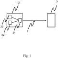
- Fig. 1 shows the schematic arrangement of the sensor 2, the measuring transmission path 1 and control unit 3, and the different sensor components.
- the sensor contains at least one sensitive component 22 and a control / evaluation unit 21.
- the signal direction of the analog electrical signal is directed from the control / evaluation unit 21 via the measuring transmission path 1 to the control unit 3.
- the sensitive component 22 consists of a temperature sensor.
- a reference element 23 is used to calibrate the first temperature-sensitive component 22.
- the calibration of the sensor takes place at a fixed temperature point at which the reference element 23 undergoes a phase transition.
- the simulation mode for calibrating the measurement transmission path 1 can then preferably be triggered by passing through the fixed temperature point for calibrating the sensor 2. Then, both the sensor 2 and the analog measuring transmission path 1 are calibrated one after the other. Subsequently, the information determined during the calibration can be transmitted in each case for the sensor 2 and the measurement transmission path 1 and documented in individual and / or common, automatically generated calibration protocols.
- Fig. 2 shows a ramp profile, as it could be used in the simulation mode for the calibration of the measuring transmission path 1 in the period between t 1 and t 2 .
- the measuring range 5 is spanned by S a and S c .
- the ramp profile scans the entire measuring range 5. This is done in the example shown in that, for defined periods of time, in each case constant signals S a , S b and S c are output by the control / evaluation unit 21, where S a is smaller than S b and S b is smaller than S c . Since the control unit 3 is designed so that the profile issued by the control / evaluation unit 21 is known to it, the control unit 3 can calibrate the measurement transmission path. In a variant, all subsequent signals are still corrected accordingly
- the control / evaluation unit 21 then outputs the deviation of the first temperature-sensitive component from the temperature point predetermined by the reference element 23. It is determined at which signal the deviation is to be output (dashed line).
- This specified signal can be set by the user.
- One possibility is to set the signal at which the deviation is output when the sensor is put into operation. For example, the user can set a parameter to a specific value.
- the control unit can determine the deviation .DELTA.S and then convert this into a temperature difference based on the parameterization and the calibration of the measurement transmission path. The temperature difference can then be stored and / or stored in a calibration log.
- Fig. 3 shows the relevant signal ranges of the analog electrical signal and their position relative to each other.
- the control unit 3 triggers a first alarm when it detects a current whose value is smaller than 3.8mA and a second alarm different from the first alarm when it detects a current whose value is larger than 20.5mA.
- the range between 3.8mA and 20.5mA can be used to display the simulation mode.
- the useful range 4 is included in the measuring range.
- the working area is chosen so that it corresponds to the maximum and minimally accepted process variables in the process. It is a true subset of the measurement range. This means that there are always unused areas in the measuring range.
- the standardized current range of 4-20mA parameterizes the temperature range of 50-180 ° C, but only minimum temperatures of 80 ° C and maximum temperatures of 150 ° C are achieved in the application. Therefore, there is an unused signal range included in the measurement range.
- the unused signal range is a first signal range corresponding to the temperature between 50-80 ° C, and a second signal range corresponding to Temperature between 150-180 ° C corresponds.
- This unused signal range can be used in the present application preferably for displaying the simulation mode.
- the lower bound of the first unused (lower) signal region is still extended to 3.8mA
- the upper bound of the second unused (upper) signal region is expanded to 20.5mA.
- the pattern of signals for displaying the simulation mode is then preferably chosen such that values from the lower and the upper unused range are output alternately from the control / evaluation unit. The idea here is to unambiguously recognize the simulation mode by outputting a signal sequence from the control / evaluation unit, which occurs with negligible probability in the measurement mode.
Description
Die Erfindung betrifft ein Verfahren zur in-situ Kalibrierung einer analogen Messübertragungsstrecke während der Bestimmung und/oder Überwachung einer Prozessgröße eines Mediums, wobei über die Messübertragungsstrecke analoge elektrische Signale von einer Regel-/Auswerteeinheit zu einer Steuerungseinheit übertragen werden. Die Regel-/Auswerteeinheit ist dabei einem Sensor zugeordnet. Der Sensor bestimmt und/oder überwacht die Prozessgröße anhand mindestens einer für die Prozessgröße sensitiven Komponente. Bei der Prozessgröße handelt es sich beispielsweise um die Temperatur, die Dichte, die Viskosität, den Druck, den Füllstand, den Durchfluss, die chemische Zusammensetzung, die Temperatur oder Analysedaten, wie den pH-Wert, die Trübung oder die Leitfähigkeit eines Mediums. Entsprechende Sensoren werden von der E+H Gruppe in unterschiedlichsten Ausgestaltungen angeboten und vertrieben. Bei dem Medium kann es sich beispielsweise um eine Flüssigkeit oder ein Gas handeln. Bei den analogen elektrischen Signalen handelt es sich beispielsweise um Ströme, Spannungen oder Kapazitäten.The invention relates to a method for in-situ calibration of an analog measurement transmission path during the determination and / or monitoring of a process variable of a medium, analog electrical signals being transmitted via the measurement transmission path from a control / evaluation unit to a control unit. The control / evaluation unit is assigned to a sensor. The sensor determines and / or monitors the process variable based on at least one component sensitive to the process variable. For example, the process variable may include temperature, density, viscosity, pressure, level, flow, chemical composition, temperature, or analytical data, such as pH, turbidity, or conductivity of a medium. Corresponding sensors are offered and distributed by the E + H Group in a wide variety of designs. The medium may be, for example, a liquid or a gas. The analog electrical signals are, for example, currents, voltages or capacitances.
Ferner betrifft die Erfindung eine Vorrichtung, deren Komponenten zur Ausführung des Verfahrens ausgestaltet sind.Furthermore, the invention relates to a device whose components are designed to carry out the method.
Üblicherweise werden die Messwerte eines Sensors dem Anwender während des Betriebs über eine Kommunikationsinfrastruktur einer sich außerhalb des Sensors befindlichen Steuerungseinheit bereitgestellt. Dies wird beispielsweise durch eine drahtlose oder eine drahtgebundene digitale Kommunikationsinfrastruktur geleistet. In einer Vielzahl von Anwendungen in der Automatisierungstechnik erfolgt die Messwertübertragung und die Energieversorgung des Sensors über eine Zweidrahtleitung. Dies ist insbesondere in den Bereichen der Automatisierungstechnik von Bedeutung, in denen Einschränkungen an die dem Sensor zugeführte Energie vorliegen, was immer der Fall ist, wenn Sensoren in explosionsgefährdeten Bereichen eingesetzt werden.Usually, the measured values of a sensor are provided to the user during operation via a communication infrastructure of a control unit located outside the sensor. This is done, for example, by a wireless or a wired digital communication infrastructure. In a large number of applications in automation technology, the measured value transmission and the energy supply of the sensor are carried out via a two-wire cable. This is particularly important in the fields of automation technology, in which there are restrictions on the energy supplied to the sensor, which is always the case when sensors are used in potentially explosive atmospheres.
Als elektrische Signale werden dabei Einheitssignale benutzt. Für Ströme existieren dabei nach der DIN IEC 60381-1 die standardisierten Messbereiche von 0-20mA und 4-20mA. Der Messbereich von 4-20mA hat dabei gegenüber dem 0-20mA Messbereich den Vorteil, dass eine Drahtüberwachung ermöglicht wird, da ein Signal von 0mA ein sicherer Hinweis auf eine Störung ist. In der Automatisierungstechnik hat sich daher der 4-20mA Standard etabliert. Zusätzlich zu dem Messbereich von 4-20mA existieren auch Standards für einen minimalen und maximalen Strom, bei dem ein Alarm ausgelöst wird. Nach der NAMUR Empfehlung NE43 wird unterhalb eines minimalen Stroms von 3,8mA und oberhalb eines maximalen Stroms von 20,5mA ein Fehleralarm ausgelöst.As electrical signals while standard signals are used. For currents, the standardized measuring ranges of 0-20mA and 4-20mA exist according to DIN IEC 60381-1. The measuring range of 4-20mA has the advantage over the 0-20mA measuring range that wire monitoring is possible, as a signal of 0mA is a sure indication of a fault. In automation technology, therefore, the 4-20mA standard has become established. In addition to the 4-20mA range, there are also standards for minimum and maximum current at which an alarm is triggered. According to NAMUR recommendation NE43, a fault alarm is triggered below a minimum current of 3.8mA and above a maximum current of 20.5mA.
Das Highway Addressable Remote Transducer (HART) Verfahren ist ein standardisiertes, weit verbreitetes digitales Kommunikationssystem, das auf den 4-20mA Standard zur Stromübertragung aufsetzt. Ein digitales Signal wird erzeugt, indem auf das analoge Signal eine hochfrequente Schwingung mit 1,2kHz und 2,2kHz aufmoduliert wird. Auch eine derartige HART Schnittstelle, welche die zusätzliche Übertragung digitaler Information über eine analoge Strom-Messübertragungsstrecke ermöglicht, ist in der Praxis nicht immer vorhanden.The Highway Addressable Remote Transducer (HART) method is a standardized, widely used digital communication system based on the 4-20mA standard for power transmission. A digital signal is generated by modulating a high-frequency oscillation at 1.2kHz and 2.2kHz on the analogue signal. Even such a HART interface, which allows the additional transmission of digital information via an analog current measurement transmission path, is not always available in practice.
In diesem Fall können zwischen dem Sensor und der Steuerungseinheit nur analoge elektrische Signale übertragen werden. Der Sensor besitzt eine Regel-/Auswerteeinheit, die die mindestens eine sensitive Komponente des Sensors ansteuert, den Messwert der mindestens einen sensitiven Komponente auswertet und ein die Prozessgröße repräsentierendes analoges elektrisches Signal erzeugt. Das analoge elektrische Signal wird dann über die analoge Messübertragungsstrecke der sich außerhalb des Sensors befindlichen Steuerungseinheit bereitgestellt. Die Steuerungseinheit ist zum Beispiel in einer Leitwarte angeordnet oder ist mit einer Leitwarte verbunden. Das elektrische Signal stammt dabei aus einem als Nutzbereich bezeichneten Wertebereich. Der Nutzbereich ist dabei so gewählt, dass er den im Prozess maximal und minimal angenommen Prozessgrößen entspricht.In this case, only analog electrical signals can be transmitted between the sensor and the control unit. The sensor has a control / evaluation unit, which controls the at least one sensitive component of the sensor, evaluates the measured value of the at least one sensitive component and generates an analog electrical signal representing the process variable. The analog electrical signal is then provided via the analog measurement transmission path of the control unit located outside the sensor. The control unit is arranged, for example, in a control room or is connected to a control room. The electrical signal originates from a value range designated as useful range. The effective range is selected so that it corresponds to the maximum and minimum process variables assumed in the process.
Der Anwender parametriert die Messübertragungsstrecke dabei so, dass der für den Prozess gewählte Nutzbereich eine echte Teilmenge des standardisierten Messbereichs ist. Eine echte Teilmenge bedeutet, dass der Nutzbereich innerhalb des standardisierten Messbereichs liegt, es aber zusätzlich noch Bereiche des Messbereichs gibt, welche während des Prozesses nicht angenommen werden, da sie unterhalb bzw. oberhalb des Nutzbereichs liegen.The user parameterizes the measuring transmission path so that the effective range selected for the process is a true subset of the standardized measuring range. A real subset means that the working range is within the standardized measuring range, but there are also areas of the measuring range that are not accepted during the process, since they are below or above the working range.
Da die analoge Messübertragungsstrecke während des Einsatzes eine Drift erfahren kann, ist oftmals eine periodische Re-Kalibrierung der analogen Messübertragungsstrecke notwendig. Hierbei wird die gesamte elektrische Schaltung, welche zur Übertragung der analogen elektrischen Signale genutzt wird, überprüft. Im Stand der Technik sind hierzu Verfahren bekannt, die simulierte elektrische Signale zur Kalibrierung benutzen. Beispielsweise vertreibt die Firma Fluke Calibration ein Gerät, das simulierte analoge elektrische Signale erzeugt, um damit eine Messübertragungsstrecke zu überprüfen und/oder zu kalibrieren. Diese Re-Kalibrierung ist mit einem Ausbau des Sensors verbunden und stellt daher einen großen Aufwand dar.Since the analog measurement transmission path can experience drift during use, a periodic re-calibration of the analog measurement transmission path is often necessary. Here, the entire electrical circuit, which is used to transmit the analog electrical signals, checked. In the prior art, methods are known which use simulated electrical signals for calibration. For example, Fluke Calibration distributes a device that generates simulated analog electrical signals in order to test and / or calibrate a measurement transmission path. This re-calibration is associated with an expansion of the sensor and therefore represents a great effort.
Die
Die
Der Erfindung liegt die Aufgabe zugrunde, ein Verfahren und eine Vorrichtung anzugeben, weiche eine in-situ Kalibrierung der Messübertragungsstrecke ermöglichen.The invention has for its object to provide a method and an apparatus that allow an in-situ calibration of the measuring transmission path.
Die Aufgabe wird erfindungsgemäß gelöst, indem der Sensor entweder in einem Messmodus oder in einem Simulationsmodus betrieben wird. Im Messmodus wandelt die Regel-/Auswerteeinheit die Messwerte der mindestens einen sensitiven Komponente des Sensors in das analoge elektrische Signal um. Im Simulationsmodus gibt die Regel-/Auswerteeinheit für eine festgelegte Zeitspanne zumindest ein eindeutig als simuliert erkennbares analoges elektrisches Signal aus, das von der Steuerungseinheit erkannt und erfasst wird. Im Simulationsmodus wird eine Kalibrierung der Messübertragungsstrecke vorgenommen, indem die Steuerungseinheit die Abweichung zwischen dem von der Regel-/Auswerteeinheit vorgegebenen analogen elektrischen Signal und dem erfassten analogen elektrischen Signals bestimmt. In einer Variante wird im Falle einer Abweichung das erfasste analoge elektrische Signal in der Steuerungseinheit noch zusätzlich entsprechend nachkorrigiert.The object is achieved according to the invention by operating the sensor either in a measuring mode or in a simulation mode. In measurement mode, the control / evaluation unit converts the measured values of the at least one sensitive component of the sensor into the analog electrical signal. In the simulation mode, the control / evaluation unit outputs at least one clearly identifiable as a simulated analog electrical signal for a fixed period of time, which is detected and detected by the control unit. In the simulation mode, the measurement transmission path is calibrated in that the control unit determines the deviation between the analog electrical signal specified by the control / evaluation unit and the detected analog electrical signal. In a variant, in the event of a deviation, the detected analog electrical signal in the control unit is additionally corrected accordingly.
Der Kern der Erfindung ist also, dass der Sensor sowohl im Messmodus, als auch im Simulationsmodus betrieben werden kann und im Simulationsmodus die analoge Messübertragungsstrecke kalibriert wird. Dadurch muss der Sensor nicht mehr ausgebaut werden, um die Messübertragungstrecke zu kalibrieren. Die in-situ Kalibrierung der analogen Messübertragungsstrecke wird durch eine geeignete Ausgestaltung der Steuerungseinheit und der Regel-/Auswerteeinheit des Sensors ermöglicht. Eine Kalibrierung der Messübertragungsstrecke kann dadurch realisiert und angezeigt werden, dass die Regel-/Auswerteeinheit für eine definierte Zeitspanne zumindest ein konstantes simuliertes analoges elektrische Signal an die Messübertragungsstrecke ausgibt.The core of the invention is thus that the sensor can be operated both in the measuring mode, as well as in the simulation mode and in the simulation mode, the analog measurement transmission path is calibrated. As a result, the sensor no longer needs to be removed to calibrate the measurement transmission path. The in-situ calibration of the analog measurement transmission path is made possible by a suitable embodiment of the control unit and the control / evaluation unit of the sensor. A calibration of the measurement transmission path can be realized and displayed by the control / evaluation unit outputting at least one constant simulated analog electrical signal to the measurement transmission path for a defined period of time.
Eine vorteilhafte Ausgestaltung des erfindungsgemäßen Verfahrens ist, dass mehrere simulierte konstante elektrische Signale nacheinander in bestimmten Zeitspannen ausgegeben werden. Die konstanten Signale unterscheiden sich in jeder bestimmten Zeitspanne um einen bestimmten Betrag von dem konstanten elektrischen Signal in der vorherigen Zeitspanne, beispielsweise um einen festen positiven Beitrag. Damit wird der standardisierte Messbereich der Messübertragungsstrecke in einem Rampenprofil abgedeckt. Das Rampenprofil ist dabei eine nicht stetige Signal-Zeit Funktion. Eine Variante sieht vor, den Messbereich durch eine streng monoton steigende Signal-Zeit Funktion abzudecken. Die Signal-Zeit Funktion kann zum Beispiel linear oder logarithmisch ist. Weitere mögliche Ausführungsformen für geeignete Signal-Zeit Funktionen, die den Messbereich abdecken, liegen der fachlich qualifizierten Person nahe.An advantageous embodiment of the method according to the invention is that a plurality of simulated constant electrical signals are output successively in certain time periods. The constant signals differ by a certain amount from the constant electrical signal in the previous period of time, for example by a fixed positive contribution, at any given time. This covers the standardized measuring range of the measuring transmission path in a ramp profile. The ramp profile is a non-continuous signal-time function. A variant provides to cover the measuring range by a strictly monotonically increasing signal-time function. The signal-time function may be, for example, linear or logarithmic. Further possible embodiments for suitable signal time functions covering the measuring range are close to the person skilled in the art.
Ein weiterer Vorteil der Erfindung ist, dass anhand des Simulationsmodus des Sensors über die analoge Messübertragungsstrecke zusätzliche Information über den Zustand des Sensors übertragen wird, welche innerhalb der Regel-/Auswerteeinheit des Sensors gewonnen wird, und in bekannten Verfahren nur über eine digitale Kommunikationsinfrastruktur oder mittels des HART Protokolls übertragen werden kann.Another advantage of the invention is that on the basis of the simulation mode of the sensor via the analog measurement transmission path additional information about the state of the sensor is transmitted, which is obtained within the control / evaluation of the sensor, and in known methods only via a digital communication infrastructure or means of the HART protocol.
In einer vorteilhaften Ausgestaltung der Erfindung wird die Abweichung zwischen dem von der Regel-/Auswerteeinheit vorgegebenen analogen elektrischen Signal und dem an der Steuerungseinheit erfassten analogen elektrischen Signal gespeichert. Dies ermöglicht beispielsweise die automatische Erstellung eines Kalibrierprotokolls zur Kalibrierung der Messübertragungsstrecke. Alternativ wird der Wert nicht in der Steuerungseinheit selber, sondern in einer separaten und mit der Steuerungseinheit verbundenen Speichereinheit gespeichert.In an advantageous embodiment of the invention, the deviation between the predetermined by the control / evaluation unit analog electrical signal and the detected on the control unit analog electrical signal is stored. This allows, for example, the automatic creation of a calibration protocol for calibrating the measurement transmission path. Alternatively, the value is not stored in the control unit itself, but in a separate memory unit connected to the control unit.
In einer bevorzugten Weiterbildung der Erfindung kann der Simulationsmodus von der Regel-/Auswerteeinheit der Steuerungseinheit dadurch angezeigt werden, dass von der Regel-/Auswerteeinheit ein voreingestelltes Muster von analogen elektrischen Signalen auf die Messübertragungsstrecke ausgegeben wird. Die Signale stammen dabei aus einem fest definierten Wertebereich. Das voreingestellte Muster ist hierbei dadurch definiert, dass für definierte Zeitspannen Abfolgen von konstanten Strömen ausgegeben werden. Die Regel-/Auswerteeinheit des Sensors ist dabei so ausgestaltet, dass sie im Simulationsmodus das Muster ausgibt. Die Steuerungseinheit ist dabei so ausgestaltet, dass sie anhand des voreingestellten Musters von analogen elektrischen Signalen erkennt, dass der Sensor im Simulationsmodus betrieben wird.In a preferred development of the invention, the simulation mode can be displayed by the control / evaluation unit of the control unit by outputting a preset pattern of analog electrical signals to the measurement transmission path from the control / evaluation unit. The signals come from a defined range of values. In this case, the preset pattern is defined by outputting sequences of constant currents for defined periods of time. The control / evaluation unit of the sensor is designed such that it outputs the pattern in the simulation mode. The control unit is designed such that it recognizes from the preset pattern of analog electrical signals that the sensor is operated in simulation mode.
In der Regel besitzen Messübertragungsstrecken, welche standardisierte Messbereiche verwenden, auch standardisierte Alarmgrenzen. Wird ein Signal an der Steuerungseinheit erfasst, welches kleiner als die untere standardisierte Alarmgrenze Smin ist, wird also ein erster Alarm ausgelöst (Low Alarm). Wird ein Signal an der Steuerungseinheit erfasst, welches größer als die obere standardisierte Alarmgrenze Smax ist, wird also ein davon verschiedener zweiter Alarm ausgelöst (High Alarm). In einer vorteilhaften Ausgestaltung der Erfindung ist der Wertebereich der analogen elektrischen Signale, welcher zur Anzeige des Simulationsmodus verwendet wird, innerhalb des Bereichs [Smin,Smax] bzw. innerhalb der Alarmgrenzen der Messübertragungsstrecke. Werden 4-20mA Ströme und die NAMUR Empfehlung NE43 verwendet, ist der Bereich zur Anzeige des Simulationsmodus in dieser vorteilhaften Ausgestaltung also das Intervall zwischen 3,8mA und 20,5mA.As a rule, measuring transmission lines which use standardized measuring ranges also have standardized alarm limits. If a signal is detected at the control unit, which is smaller than the lower standardized alarm limit S min , so a first alarm is triggered (low alarm). If a signal is detected at the control unit which is greater than the upper standardized alarm limit S max , then a different second alarm is triggered (high alarm). In an advantageous embodiment of the invention, the value range of the analog electrical signals used to display the simulation mode is within the range [S min , S max ] or within the alarm limits of the measurement transmission path. If 4-20mA currents and the NAMUR recommendation NE43 are used, the range for displaying the simulation mode in this advantageous embodiment is therefore the interval between 3.8mA and 20.5mA.
In einer weiteren Ausgestaltung der Erfindung ist der Wertebereich der analogen elektrischen Signale, welcher zur Anzeige des Simulationsmodus verwendet wird, so gewählt, dass er keine Überschneidung mit dem Nutzbereich besitzt. Da der Nutzbereich eine echte Teilmenge des Messbereichs ist, kann der ungenutzte Bereich des Bereichs [Smin,Smax] zur Anzeige des Simulationsmodus verwendet werden kann. In dieser vorteilhaften Ausgestaltung wird also genau der Bereich zur Anzeige des Simulationsmodus verwendet, der im Messmodus während der Messung der Prozessgröße nicht genutzt wird.In a further embodiment of the invention, the range of values of the analog electrical signals which is used to display the simulation mode is selected such that it has no overlap with the useful range. Since the payload is a true subset of the measurement range, the unused range of the range [S min , S max ] can be used to display the simulation mode. In this advantageous embodiment, therefore, exactly the area for displaying the simulation mode is used, which is not used in the measuring mode during the measurement of the process variable.
In einer vorteilhaften Weiterbildung des Verfahrens vollzieht die Regel-/Auswerteeinheit des Sensors während der Messung der Prozessgröße automatisch einen Wechsel in den Simulationsmodus. Die Bedingung dafür ist, dass zumindest eine sensitive Komponente einen bestimmten Wert annimmt. Es ist also möglich, einen oder mehrere Werte für die Prozessgröße vorzugeben, bei dem/denen der Sensor in den Simulationsmodus wechselt. Eine Variante ist, dass die Bedingung für den Wechsel in den Simulationsmodus durch eine Kombination der Messwerte von mehreren sensitiven Komponenten definiert wird. Der/Die bestimmte/bestimmten Wert/Werte, bei dem/denen ein Wechsel in den Simulationsmodus ausgelöst wird, ist/sind dabei beispielsweise vom Anwender anhand eines oder mehrerer Parameter einstellbar.In an advantageous development of the method, the control / evaluation unit of the sensor automatically performs a change to the simulation mode during the measurement of the process variable. The condition for this is that at least one sensitive component assumes a certain value. It is thus possible to specify one or more values for the process variable at which the sensor changes to the simulation mode. A variant is that the condition for the change to the simulation mode is defined by a combination of the measured values of several sensitive components. The determined value (s) at which a change to the simulation mode is triggered is / are, for example, adjustable by the user on the basis of one or more parameters.
Gemäß einer vorteilhaften Ausgestaltung der Erfindung ist die Regel-/Auswerteinheit in der Lage, im Simulationsmodus eine Gutmeldung, eine Warnungsmeldung und/oder eine Fehlermeldung über den Zustand des Sensors zu erstellen und über die Messübertragungsstrecke zu übertragen. Die Gutmeldung wird anhand eines ersten voreingestellten Musters von analogen elektrischen Signalen ausgegeben. Die Warnungsmeldung wird anhand eines zweiten, vom ersten Muster verschiedenen Musters von analogen elektrischen Signalen ausgegeben. Die Fehlermeldung wird anhand eines vom ersten und zweiten Muster verschiedenen, dritten voreingestellten Muster von analogen elektrischen Signalen ausgegeben. Die Gutmeldung, Warnungsmeldung und/oder Fehlermeldung wird über die Messübertragungsstrecke übermittelt. Die Steuerungseinheit erkennt anhand der empfangenen, voreingestellten und voneinander unterscheidbaren Muster, ob es sich um ein Gutmeldung, eine Warnungsmeldung, und/oder eine Fehlermeldung handelt. Der Bereich zur Anzeige der Gut- und Warnungsmeldung liegt dabei gerade innerhalb der Alarmgrenzen bzw. innerhalb des Wertebereichs [Smin,Smax]. Die analogen elektrischen Signale zur Anzeige der Fehlermeldung liegen außerhalb [Smin,Smax]. Die Gut- und/oder Warnungsmeldung kann dann in der Steuerungseinheit gespeichert werden bzw. in einer separaten, mit der Steuerungseinheit verbundenen Speichereinheit gespeichert werden.According to an advantageous embodiment of the invention, the control / evaluation unit is able to create a good message, a warning message and / or an error message about the state of the sensor in the simulation mode and to transmit it via the measurement transmission path. The good message is output from a first preset pattern of analog electrical signals. The warning message is output from a second pattern of analog electrical signals other than the first pattern. The error message is output from a third preset pattern of analog electrical signals, different from the first and second patterns. The good message, warning message and / or error message is transmitted via the measuring transmission path. The control unit recognizes on the basis of the received, preset and distinguishable patterns, whether it is a good message, a warning message, and / or an error message. The range for displaying the good and warning message lies just within the alarm limits or within the value range [S min , S max ]. The analogue electrical signals for displaying the error message are outside [S min , S max ]. The good and / or warning message can then be stored in the control unit or stored in a separate memory unit connected to the control unit.
In dieser vorteilhaften Ausgestaltung kann also im Simulationsmodus qualitative, den Sensor betreffende Information von der Regel-/Auswerteeinheit zur Steuerungseinheit übertragen werden. Die vorliegende Erfindung erlaubt die Übertragung zusätzlicher Information über die analoge Messübertragungsstrecke, ohne dafür eine HART Schnittstelle zu benötigen.In this advantageous embodiment, therefore, in the simulation mode, qualitative information relating to the sensor can be transmitted from the control / evaluation unit to the control unit. The present invention allows the transmission of additional information over the analog measurement transmission path, without requiring a HART interface.
Es ist weiterhin zu bedenken, dass die mindestens eine sensitive Komponente des Sensors ihren Messwert auch im Simulationsmodus der Regel-/Auswerteeinheit übermittelt. Zwar übermittelt die Regel-/Auswerteeinheit im Simulationsmodus den Messwert nicht mehr über die Messübertragungsstrecke an die Steuerungseinheit weiter. Die Regel-/Auswerteeinheit ist aber auch im Simulationsmodus in der Lage, eine Fehlermeldung auszulösen, falls die Messgrößen einer oder mehrerer sensitiver Komponenten des Sensors kritische Werte für die Prozessgröße über- und/oder unterschreitet. Diese kritischen Werte sind innerhalb der Regel-/Auswerteeinheit festlegt. Das erfindungsgemäße Verfahren ermöglicht also beispielsweise, gleichzeitig eine Gutmeldung zu übertragen und parallel weiterhin die Prozessgröße zu überwachen, so dass auch im Simulationsmodus eine Warnungs- oder Fehlermeldung in der Regel-/Auswerteeinheit generiert wird. Es ist beispielsweise also möglich, eine Kalibrierung der Messübertragungsstrecke auszulösen, falls die temperatursensitive Komponente eine Temperatur von 120° C misst, und gleichzeitig während der Kalibrierung der Messübertragungsstrecke von der Regel-/Auswerteeinheit überwachen zu lassen, dass die Temperatur von 120°C immer überschritten oder unterschritten ist. Die lückenlose Einhaltung einer Überwachungstemperatur ist für die hygienischen Anforderungen im Lebensmittel- und/oder Pharmaziebereich von großer Bedeutung. Das Verfahren der vorliegenden Anmeldung ermöglicht auch im Simulationsmodus eine lückenlose Überwachung der Temperatur.It is further to be considered that the at least one sensitive component of the sensor also transmits its measured value in the simulation mode of the control / evaluation unit. Although the control / evaluation unit in the simulation mode no longer transmits the measured value to the control unit via the measuring transmission path. The control / evaluation unit is also in simulation mode in a position, a Error message to trigger if the measured variables of one or more sensitive components of the sensor exceeds and / or falls below critical values for the process variable. These critical values are defined within the control / evaluation unit. The method according to the invention thus makes it possible, for example, to simultaneously transmit a good message and to continue to monitor the process variable in parallel so that a warning or error message is also generated in the control / evaluation unit in the simulation mode. It is therefore possible, for example, to initiate a calibration of the measurement transmission path if the temperature-sensitive component measures a temperature of 120 ° C. and at the same time to allow the control / evaluation unit to monitor during the calibration of the measurement transmission path that the temperature always exceeds 120 ° C. or fallen below. Full compliance with a monitoring temperature is of great importance for hygienic requirements in the food and / or pharmaceutical sector. The method of the present application also allows seamless monitoring of the temperature in the simulation mode.
Eine Fehlermeldung des Sensors kann nur durch einen manuellen Eingriff am Sensor und/oder der Messübertragungsstrecke behoben werden. Im Gegensatz dazu sieht eine Weiterbildung der Erfindung vor, dass der Sensor nach Ausgabe einer Gut- und/oder Warnungsmeldung wieder selbständig in den Messmodus versetzt wird.An error message from the sensor can only be rectified by manual intervention on the sensor and / or the measuring transmission path. In contrast, a further development of the invention provides that the sensor is again placed in the measuring mode after issuing a good and / or warning message.
Der Wechsel vom Betrieb des Sensors im Messmodus zum Betrieb des Sensor im Simulationsmodus zur in-situ Kalibrierung der Messübertragungsstrecke, sowie der Rückwechsel vom Betrieb des Sensors im Simulationsmodus zum Betrieb des Sensors im Messmodus kann in der vorliegenden Erfindung also komplett automatisch erfolgen. Der Wechsel in den Simulationsmodus kann dadurch ausgelöst werden, dass zumindest eine sensitive Komponente einen Wert annimmt, und der Rückwechsel in den Messmodus folgt nach der Gut- und/oder Warnungsmeldung selbständig.The change from the operation of the sensor in the measuring mode to the operation of the sensor in the simulation mode for in-situ calibration of the measuring transmission path, as well as the return change from the operation of the sensor in the simulation mode for operating the sensor in the measuring mode can be done completely automatically in the present invention. The change to the simulation mode can be triggered by the fact that at least one sensitive component assumes a value, and the return to the measurement mode follows automatically after the good and / or warning message.
Zusätzlich dazu sieht eine weitere Weiterbildung vor, dass der Wechsel in den Simulationsmodus auch manuell erfolgen kann. Beispielsweise kann eine Spannungsunterbrechung den Wechsel in den Simulationsmodus und die in-situ Kalibrierung der Messübertragungsstrecke veranlassen. Da bei der Inbetriebnahme des Sensors eine Spannungsunterbrechung erfolgt, stellt dies eine besonders vorteilhaft Weiterbildung dar, da somit die Kalibrierung der Messübertragungsstrecke einen Teil der Routine zur Inbetriebnahme des Sensors darstellt. Andere Möglichkeiten eines manuellen Eingriffs zum Wechsel in den Simulationsmodus sind das Auslösen eines am Sensor befindlichen Schalters.In addition, a further development provides that the change to the simulation mode can also be done manually. For example, a power interruption may cause the change to the simulation mode and the in-situ calibration of the measurement transmission path. Since a power interruption occurs during the commissioning of the sensor, this represents a particularly advantageous development, since thus the calibration of the measuring transmission path is part of the routine for commissioning the sensor. Other ways of manual intervention to change to simulation mode are triggering a switch located on the sensor.
Weiter ist eine kontaktlose Auslösung möglich, welche von außerhalb durch einen Magneten betätigt wird, beispielsweise durch ein Reed Relais oder eine Hall Sonde im Sensor. Eine weitere Möglichkeit für eine kontaktlose Auslösung besteht weiter durch eine kurzreichweitige Funkverbindung mit dem Sensor, beispielsweise im Infrarotbereich, durch Bluetooth, oder durch Near-Field-Communication. Andere derartige manuelle kontaktlose Auslösungen liegen dem Fachmann nahe. Dabei muss der Sensor so ausgestaltet sein, dass er ein zusätzliches, zur kontaktlosen Auslösung befähigtes Gerät aufweist.Next, a contactless release is possible, which is actuated from outside by a magnet, for example by a reed relay or a Hall probe in Sensor. Another possibility for a contactless triggering is a short-range radio link with the sensor, for example in the infrared range, by Bluetooth, or by near-field communication. Other such manual contactless releases are obvious to those skilled in the art. The sensor must be designed so that it has an additional, capable of contactless triggering device.
Das erfindungsgemäße Verfahren sieht damit also auch vor, dass der Anwender des Sensors bestimmen kann, ob der Wechsel in den Simulationsmodus automatisch oder durch einen manuellen Eingriff erfolgt.The method according to the invention therefore also provides that the user of the sensor can determine whether the changeover to the simulation mode takes place automatically or by means of a manual intervention.
Ferner beinhaltet die Erfindung eine Vorrichtung zur in-situ Kalibrierung einer analogen Messübertragungsstrecke während der Bestimmung und/oder Überwachung einer Prozessgröße eines Mediums, wobei die Vorrichtung zur Durchführung des Verfahrens ausgestaltet ist. Die Vorrichtung weist einen Sensor und eine Steuerungseinheit auf, wobei der Sensor mindestens eine sensitive Komponente und eine Regel-/Auswerteeinheit besitzt, und wobei die Regel-/Auswerteeinheit über die Messübertragungsstrecke mit der Steuerungseinheit verbunden ist.Furthermore, the invention includes a device for in-situ calibration of an analog measurement transmission path during the determination and / or monitoring of a process variable of a medium, wherein the device is designed for carrying out the method. The device has a sensor and a control unit, wherein the sensor has at least one sensitive component and a control / evaluation unit, and wherein the control / evaluation unit is connected to the control unit via the measurement transmission path.
In einer besonders vorteilhaften Ausgestaltung der Vorrichtung handelt es sich bei dem Sensor um ein Thermometer, wobei der Sensor eine temperatursensitive Komponente und ein Referenzelement aufweist, welches bei zumindest einem vorgegeben Temperaturpunkt eine Phasenumwandlung erfährt. Die Regel-/Auswerteeinheit kalibriert bei dem festen Temperaturpunkt die temperatursensitive Komponente anhand des Referenzelements, indem die Abweichung der ersten temperatursensitiven Komponente von dem durch das Referenzelement vorgegebenen Temperaturpunkt bestimmt wird. Ein derartiges in-situ kalibrierendes Thermometer ist in der
Wird ein in-situ kalibrierendes Thermometer zusammen mit einer analogen Messübertragungsstrecke betrieben, muss die Messübertragungsstrecke im Langzeitbetrieb auch in regelmäßigen Intervallen kalibriert werden. Zur Kalibrierung der Messübertragungsstrecke muss das Thermometer dann wieder ausgebaut werden muss. Der technische Vorteil eines sich selbst kalibrierenden und validierenden Thermometers wäre bei der Verwendung einer analogen Messübertragungsstrecke damit wieder teilweise aufgehoben. Die vorliegende Anmeldung erlaubt also, sowohl eine in-situ Kalibrierung des Thermometers als auch eine in-situ Kalibrierung der analogen Messübertragungsstrecke durchzuführen. In dieser vorteilhaften Ausgestaltung der Vorrichtung ermöglicht die vorliegende Erfindung damit, alle technischen Vorteile des in-situ kalibrierenden Thermometers auch dann vollständig zu realisieren, selbst wenn die dafür vorgesehene digitale Kommunikationsinfrastruktur oder HART Schnittstelle nicht vorhanden ist.If an in-situ calibrating thermometer is operated together with an analog measurement transmission path, the measurement transmission path must also be calibrated at regular intervals during long-term operation. To calibrate the measuring transmission path, the thermometer must then be removed again. The technical advantage of a self-calibrating and validating thermometer would thus be partially canceled when using an analog measurement transmission path. The present application thus makes it possible to carry out both an in-situ calibration of the thermometer and an in-situ calibration of the analog measurement transmission path. In this advantageous embodiment of the device, the present invention thus allows all technical advantages of in-situ even if the dedicated digital communication infrastructure or HART interface is not available.
Insbesondere kann in dieser besonders vorteilhaften Ausgestaltung der Simulationsmodus dazu genutzt werden, die bei der Kalibrierung der temperatursensitiven Komponente des Sensors gewonnene Information über die analoge Messübertragungsstrecke zu übertragen. Dabei wird in einer Weiterbildung im Simulationsmodus von der Regel-/Auswerteeinheit für eine festgelegte Zeit ein konstantes elektrisches Signal ausgegeben, welches der Abweichung der temperatursensitiven Komponente von dem durch das Referenzelement vorgegebenen Temperaturpunkt entspricht.In particular, in this particularly advantageous embodiment, the simulation mode can be used to transmit the information obtained during the calibration of the temperature-sensitive component of the sensor via the analog measurement transmission path. In a further development in the simulation mode, the control / evaluation unit outputs a constant electrical signal for a defined time, which corresponds to the deviation of the temperature-sensitive component from the temperature point predetermined by the reference element.
Der Anwender kann dabei, beispielsweise anhand eines Parameters bei Inbetriebnahme des Sensors, ein bestimmtes konstantes elektrisches Signal festlegen, bei dem die Abweichung der temperatursensitiven Komponente von dem durch das Referenzelement vorgegebenen Temperaturpunkt angezeigt wird. Die Steuerungseinheit erkennt somit anhand der Abweichung des von der Regel-/Auswerteeinheit ausgegebenen konstanten elektrischen Signals von dem festgelegten analogen elektrischen Signal sowie anhand der Parametrierung der Messübertragungsstrecke die Abweichung der temperatursensitiven Komponente von dem durch das Referenzelement vorgegebenen Temperaturpunkt.The user can set, for example, based on a parameter when commissioning the sensor, a specific constant electrical signal, in which the deviation of the temperature-sensitive component is displayed by the predetermined by the reference element temperature point. The control unit thus recognizes the deviation of the temperature-sensitive component from the temperature point predetermined by the reference element on the basis of the deviation of the constant electrical signal output by the control / evaluation unit from the specified analog electrical signal and on the basis of the parameterization of the measurement transmission path.
Gemäß einer vorteilhaften Weiterbildung der erfindungsgemäßen Vorrichtung wird auch die Abweichung der temperatursensitiven Komponente von dem durch das Referenzelement vorgegebenen Temperaturpunkt nach der Übertragung über die Messübertragungsstrecke in der Steuerungseinheit gespeichert. Alternativ kann die Abweichung auch in einer separaten, mit der Steuerungseinheit verbundenen Speichereinheit gespeichert werden. Diese Weiterbildung ermöglicht auch die automatische Erstellung eines Kalibrierprotokolls zur Kalibrierung des Sensors. Dies beinhaltet auch ein gemeinsames Kalibrierprotokoll, welches die Kalibrierinformation für den Sensor und für die Messübertragungsstrecke enthält.According to an advantageous development of the device according to the invention, the deviation of the temperature-sensitive component from the temperature point predetermined by the reference element is also stored in the control unit after transmission via the measuring transmission path. Alternatively, the deviation may also be stored in a separate memory unit connected to the control unit. This development also allows the automatic creation of a calibration protocol for calibrating the sensor. This also includes a common calibration protocol which contains the calibration information for the sensor and for the measurement transmission path.
Im Gegensatz zu der in der
Im gleichen Maße lässt sich die Erfindung in naheliegender Weise auf weitere Sensoren verallgemeinern, die andere Prozessgrößen als die Temperatur messen. Erfolgt eine in-situ Kalibrierung des Sensors (beispielsweise durch die Verwendung mehrerer sensitiver Komponenten) und wird eine analoge Messübertragungsstrecke verwendet, so kann die vorliegende Erfindung mutatis mutandis auch auf derartige Vorrichtungen angewendet werden.To the same extent, the invention can be generalized to other sensors that measure process variables other than temperature. If an in-situ calibration of the sensor is carried out (for example by using a plurality of sensitive components) and if an analog measurement transmission path is used, then the present invention can also be applied mutatis mutandis to such devices.
Die Erfindung wird anhand der nachfolgenden Figuren näher erläutert. Es zeigt:
-
Fig. 1 : eine schematische Darstellung gemäß einer Ausgestaltung der erfindungsgemäßen Vorrichtung. -
Fig. 2 : ein Rampenprofil, das zur Kalibrierung der Messübertragungsstrecke verwendet werden kann -
Fig. 3 : die verschiedenen Signalbereiche des analogen elektrischen Signals.
-
Fig. 1 : a schematic representation according to an embodiment of the device according to the invention. -
Fig. 2 : a ramp profile that can be used to calibrate the measurement transmission path -
Fig. 3 : the different signal ranges of the analog electrical signal.
In einer besonders bevorzugten Ausführung besteht die sensitive Komponente 22 aus einem Temperatursensor. Ein Referenzelement 23 wird zur Kalibrierung der ersten temperatursensitiven Komponente 22 benutzt. Die Kalibrierung des Sensors erfolgt an einem festen Temperaturpunkt, bei dem das Referenzelement 23 einen Phasenübergang erfährt. In diesem Ausführungsbeispiel kann dann der Simulationsmodus zur Kalibrierung der Messübertragungsstrecke 1 bevorzugt dadurch ausgelöst werden, dass der feste Temperaturpunkt zur Kalibrierung des Sensors 2 durchlaufen wurde. Es werden dann also hintereinander sowohl der Sensor 2, als auch die analoge Messübertragungsstrecke 1 kalibriert. Anschließend können die bei der Kalibrierung festgestellten Informationen jeweils für den Sensor 2 und die Messübertragungsstrecke 1 übertragen werden und in einzelnen und/oder gemeinsamen, automatisch erstellten Kalibrierprotokollen dokumentiert werden.In a particularly preferred embodiment, the
Wird die bevorzugte Ausgestaltung der Erfindung mit einer temperatursensitiven Komponenten 22 und einem Referenzelement 23 ausgeführt, gibt die Regel-/Auswerteeinheit 21 anschließend noch die Abweichung der ersten temperatursensitiven Komponente von dem durch das Referenzelement 23 vorgegebenen Temperaturpunkt aus. Dabei ist festgelegt, bei welchem Signal die Abweichung ausgegeben werden soll (gestrichelte Linie). Dieses festgelegte Signal kann dabei vom Anwender eingestellt werden. Eine Möglichkeit ist dabei, das Signal, an dem die Abweichung ausgegeben wird, bei Inbetriebnahme des Sensors einzustellen. Der Anwender kann dafür zum Beispiel einen Parameter auf einen bestimmen Wert festsetzen. Die Steuerungseinheit kann die Abweichung ΔS bestimmen und diese anhand der Parametrierung und der Kalibrierung der Messübertragungsstrecke anschließend in eine Temperaturdifferenz umrechnen. Die Temperaturdifferenz kann dann gespeichert und/oder in einem Kalibrierprotokoll hinterlegt werden.If the preferred embodiment of the invention is implemented with a temperature-
Der Nutzbereich 4 ist im Messbereich enthalten. Der Nutzbereich ist dabei so gewählt, dass erden im Prozess maximal und minimal angenommen Prozessgrößen entspricht. Er ist eine echte Teilmenge des Messbereichs. Das bedeutet, dass es im Messbereich immer ungenutzte Bereiche gibt. Beispielsweise parametriert der standardisierte Strombereich von 4-20mA das Temperaturintervall von 50-180°C, in der Anwendung werden aber nur minimale Temperaturen von 80°C und maximale Temperaturen von 150°C erreicht. Daher gibt es einen im Messbereich enthaltenen ungenutzten Signalbereich. Insbesondere ist der ungenutzte Signalbereich ein erster Signalbereich, der der Temperatur zwischen 50-80°C entspricht, und ein zweiter Signalbereich, der der Temperatur zwischen 150-180°C entspricht. Dieser ungenutzte Signalbereich kann in der vorliegenden Anwendung bevorzugt zur Anzeige des Simulationsmodus genutzt werden. In bevorzugter Weise wird dabei die untere Schranke des ersten ungenutzten (unteren) Signalbereichs noch auf 3,8mA erweitert, und die obere Schranke des zweiten ungenutzten (oberen) Signalbereichs wird auf 20,5mA erweitert. Das Muster von Signalen zur Anzeige des Simulationsmodus ist dann bevorzugt so gewählt, dass abwechselnd Werte aus dem unteren und dem oberen ungenutzten Bereich von der Regel-/Auswerteeinheit ausgegeben werden. Die Idee ist hierbei, den Simulationsmodus dadurch eindeutig zu erkennen, dass eine Signalabfolge von der Regel-/Auswerteeinheit ausgegeben wird, die im Messmodus mit verschwindender Wahrscheinlichkeit vorkommt.The
- 11
- MessübertragungsstreckeMeasuring transmission link
- 22
- Sensorsensor
- 2121
- Regel-/AuswerteeinheitControl / evaluation unit
- 2222
- erste sensitive Komponentefirst sensitive component
- 2323
- Referenzelementreference element
- 33
- Steuerungseinheitcontrol unit
- 44
- Nutzbereichuseful region
- 55
- Messbereichmeasuring range
- Smin S min
- minimales analoges elektrisches Signalminimal analog electrical signal
- Smax S max
- maximales analoges elektrisches Signalmaximum analog electrical signal
- ΔS.DELTA.S
- analoges elektrische Signal, welches der Abweichung der ersten temperatursensitiven Komponente von dem durch das Referenzelement vorgegebenen Temperaturpunkt entsprichtanalog electrical signal corresponding to the deviation of the first temperature-sensitive component from the predetermined by the reference element temperature point
Claims (15)
- Procedure for the in-situ calibration of an analog measuring transmission section (1) during the determination and/or monitoring of a process variable of a medium,
wherein analog electrical signals are transmitted from a control/evaluation unit (21) to a control unit (3) via the measuring transmission section (1),
wherein the control/evaluation unit (21) is assigned a sensor (2), which determines and/or monitors the process variable using at least one component (22) which is sensitive to the process variable,
wherein the sensor (2) is operated either in a measuring mode or in a simulation mode,
wherein, in the measuring mode, the control/evaluation unit (21) converts the measured values of the at least one component (22) which is sensitive to the process variable into an analog electrical signal that represents the process variable,
wherein, in the simulation mode, the control/evaluation unit (21) outputs at least one analog electrical signal, which is clearly identified as simulated, for a defined period of time, said signal being detected and measured by the control unit (3), and wherein, in the simulation mode, the measuring transmission section (1) is calibrated by the control unit (3) determining the deviation between the analog electrical signal predefined by the control/evaluation unit (21) and the measured analog electrical signal. - Procedure as claimed in Claim 1,
wherein, in the simulation mode, the deviation between the analog electrical signal predefined by the control/evaluation unit (21) and the analog electrical signal measured at the control unit (3) is saved. - Procedure as claimed in Claim 1 or 2,
wherein, in the simulation mode, the control/evaluation unit (21) outputs a predefined pattern of analog electrical signals from a fixed value range, and wherein the control unit (3) detects that the sensor (2) is being operated in the simulation mode on the basis of the preset pattern of analog electrical signals. - Procedure as claimed in at least one of the previous claims,
wherein the control unit (3) triggers a first alarm if it detects a signal whose value is less than a minimum analog electrical signal Smin,
wherein the control unit (3) triggers a second alarm that differs from the first alarm if it detects a signal whose value is greater than a maximum analog electrical signal Smax. - Procedure as claimed in Claim 3 and 4,
wherein the fixed value range, which is used by the control/evaluation unit (21) to indicate the simulation mode, is located in the range [Smin, Smax]. - Procedure as claimed in Claim 4 and 5,
wherein the analog electrical signals output in the measuring mode come from a value range known as the useful range (4),
wherein the useful range (4) is configured in such a way that it corresponds to the process variables taken to be the maximum and minimum in the process, wherein the useful range (4) is a real subsection of [Smin, Smax],
and wherein the value range which is used by the control/evaluation unit (21) to indicate the simulation mode does not overlap with the useful range (4). - Procedure as claimed in at least one of the previous claims,
wherein a change to the simulation mode is caused if at least one sensitive component (22) of the sensor (2) adopts at least one defined value. - Procedure as claimed in at least one of the previous claims,
wherein, in the simulation mode, an OK message, a warning message and/or an error message regarding the condition of the sensor (2) is output, wherein, in the event of an OK message, the control/evaluation unit (21) outputs a first predefined pattern of analog electrical signals,
wherein, in the event of a warning message, the control/evaluation unit (21) outputs a second predefined pattern of analog electrical signals that is different from the first pattern,
wherein, in the event of an error message, the control/evaluation unit (21) outputs a third predefined pattern of analog electrical signals that is different from the first and second pattern,
wherein the analog electrical signals to indicate the OK and warning message are in the value range [Smin, Smax],
and wherein the analog electrical signals to indicate the error message are outside the range [Smin, Smax],
and wherein the OK message and/or the warning message is/are saved. - Procedure as claimed in Claim 8,
wherein the sensor (2) returns to the measuring mode after outputting an OK or warning message. - Procedure as claimed in one of the previous claims,
wherein a change to the simulation mode is triggered manually, preferably by an interruption in the power to the sensor (2), by activating a solenoid switch and/or by near field communication. - Apparatus for the in-situ calibration of an analog measuring transmission section (1) during the determination and/or monitoring of a process variable of a medium,
wherein the apparatus is designed to perform the procedure as claimed in at least one of the Claims 1 to 10
with a sensor (2) and a control unit,
wherein the sensor (2) has at least a sensitive component (22) and a control/evaluation unit (21),
and wherein the control/evaluation unit (21) is connected to the control unit (3) via the measuring transmission section (1). - Apparatus as claimed in Claim 11,
wherein the sensor (2) has a temperature-sensitive component (22) and a reference element (23), which experiences a phase transition at the level of at least one predefined temperature point,
wherein, at the fixed temperature point, the control/evaluation unit (21) calibrates the temperature-sensitive component (22) using the reference element (23) and determines the deviation of the temperature-sensitive component (22) from the temperature point predefined by the reference element (23),
and wherein the control/evaluation unit (21) causes a change from the measuring mode to the simulation mode when the reference element (23) goes through the predefined temperature point. - Apparatus as claimed in Claim 12,
wherein, in the simulation mode, the control/evaluation unit (21) outputs a constant analog electrical signal for a defined period of time following the calibration of the temperature-sensitive component (22) and the measuring transmission section (1), said signal corresponding to the deviation of the temperature-sensitive component (22) from the temperature point defined by the reference element (23);
wherein the control unit (3) uses the deviation ΔS of the constant electrical signal, which is output by the control/evaluation unit (21), from a defined analog electrical signal and uses the parameterization of the measuring transmission section (1) to detect the deviation of the temperature-sensitive component (22) from the temperature point defined by the reference element (23). - Apparatus as claimed in Claim 13,
wherein, in the simulation mode, the control unit (3) saves the deviation of the temperature-sensitive component (22) from the temperature point defined by the reference element (23). - Apparatus as claimed in Claim 13 or 14,
wherein the control/evaluation unit (21) generates an OK message if the deviation of the temperature-sensitive component (22) from the temperature point defined by the reference element (23) is below a defined limit value,
and wherein the control/evaluation unit (21) generates a warning message if the deviation of the temperature-sensitive component (22) from the temperature point defined by the reference element (23) exceeds a defined limit value.
Applications Claiming Priority (2)
| Application Number | Priority Date | Filing Date | Title |
|---|---|---|---|
| DE102015120072.4A DE102015120072A1 (en) | 2015-11-19 | 2015-11-19 | Method for in-situ calibration of an analog measurement transmission path and corresponding device |
| PCT/EP2016/075322 WO2017084828A1 (en) | 2015-11-19 | 2016-10-21 | Method for the in situ calibration of an analog measurement transmission path, and corresponding device |
Publications (2)
| Publication Number | Publication Date |
|---|---|
| EP3377861A1 EP3377861A1 (en) | 2018-09-26 |
| EP3377861B1 true EP3377861B1 (en) | 2019-09-04 |
Family
ID=57211492
Family Applications (1)
| Application Number | Title | Priority Date | Filing Date |
|---|---|---|---|
| EP16788473.3A Active EP3377861B1 (en) | 2015-11-19 | 2016-10-21 | In-situ calibration method of an analog measurement transmission connection and corresponding apparatus |
Country Status (5)
| Country | Link |
|---|---|
| US (1) | US10989574B2 (en) |
| EP (1) | EP3377861B1 (en) |
| CN (1) | CN108291825B (en) |
| DE (1) | DE102015120072A1 (en) |
| WO (1) | WO2017084828A1 (en) |
Families Citing this family (4)
| Publication number | Priority date | Publication date | Assignee | Title |
|---|---|---|---|---|
| DE102015115535A1 (en) * | 2015-09-15 | 2017-03-16 | Endress + Hauser Wetzer Gmbh + Co Kg | Method for calibrating a temperature sensor located in a process of automation technology |
| DE102018122014A1 (en) * | 2018-09-10 | 2020-03-12 | Endress + Hauser Flowtec Ag | Measuring system and measuring arrangement thus formed |
| DE102019107625A1 (en) * | 2018-12-20 | 2020-06-25 | Endress+Hauser Conducta Gmbh+Co. Kg | Method for in-process adjustment of a potentiometric sensor of a measuring arrangement |
| DE102019134019A1 (en) * | 2019-12-11 | 2021-06-17 | Endress + Hauser Wetzer Gmbh + Co. Kg | In situ calibration of a thermometer |
Family Cites Families (16)
| Publication number | Priority date | Publication date | Assignee | Title |
|---|---|---|---|---|
| US4532601A (en) * | 1982-08-19 | 1985-07-30 | Westinghouse Electric Corp. | Automatic temperature calibration method and apparatus |
| DE4121637C2 (en) * | 1991-06-29 | 1997-04-24 | Bosch Gmbh Robert | Process for testing control units and test equipment for carrying out the process |
| US20030158683A1 (en) * | 2002-02-19 | 2003-08-21 | Claude Gauthier | Temperature calibration using on-chip electrical fuses |
| DE102005041427A1 (en) * | 2005-08-31 | 2007-03-01 | Endress + Hauser Conducta Gesellschaft für Mess- und Regeltechnik mbH + Co. KG | Sensor e.g. gas sensor, simulator for testing process system behavior, has control circuit that simulates temporal processing of measuring signals of sensors and provides corresponding output signal to measuring section interface |
| CN101334308B (en) * | 2007-06-29 | 2013-03-27 | 通用电气公司 | Artificial circuit for checking flow gauge |
| US7715669B2 (en) * | 2007-10-17 | 2010-05-11 | Avago Technologies Fiber Ip (Singapore) Pte. Ltd. | Fiber optic link, a transceiver for use in the link, and methods for designing and constructing fiber optic links and transceivers |
| DE102008050612A1 (en) * | 2008-10-09 | 2010-04-15 | Endress + Hauser Conducta Gesellschaft für Mess- und Regeltechnik mbH + Co. KG | Method for testing the behavior of a process plant |
| EP2216635B1 (en) * | 2009-02-06 | 2019-07-17 | Mettler-Toledo GmbH | Calibrating device for a power measurement device and power measurement device |
| DE102009058282B3 (en) | 2009-12-14 | 2011-02-17 | Temperaturmeßtechnik Geraberg GmbH | Apparatus for measuring temperature of e.g. gas, has two ceramic substrates with linear thermal expansion coefficients less than and greater than linear thermal expansion coefficients of temperature measuring resistors, respectively |
| DE102010040039A1 (en) * | 2010-08-31 | 2012-03-01 | Endress + Hauser Wetzer Gmbh + Co Kg | Method and device for in situ calibration of a thermometer |
| DE102011107856A1 (en) * | 2011-07-18 | 2013-01-24 | Abb Technology Ag | Temperature sensor with means for in-situ calibration |
| US20130144549A1 (en) | 2011-12-01 | 2013-06-06 | Grigori Temkine | Method for calibrating temperature sensors using reference voltages |
| DE102012103464A1 (en) * | 2012-04-19 | 2013-10-24 | Brose Fahrzeugteile Gmbh & Co. Kommanditgesellschaft, Hallstadt | Actuator of an air passage device and method for controlling an actuator |
| US20140200840A1 (en) * | 2012-12-19 | 2014-07-17 | Instrument Works Pty Ltd | Platform for Portable Sensing Applications |
| DE102012112782A1 (en) * | 2012-12-20 | 2014-06-26 | Endress + Hauser Conducta Gesellschaft für Mess- und Regeltechnik mbH + Co. KG | Method and device for determining a state of a sensor integrated in a process vessel |
| DE102013100799A1 (en) * | 2012-12-21 | 2014-06-26 | Endress + Hauser Flowtec Ag | Converter circuit with a current interface and measuring device with such a converter circuit |
-
2015
- 2015-11-19 DE DE102015120072.4A patent/DE102015120072A1/en not_active Ceased
-
2016
- 2016-10-21 CN CN201680065409.9A patent/CN108291825B/en active Active
- 2016-10-21 WO PCT/EP2016/075322 patent/WO2017084828A1/en active Application Filing
- 2016-10-21 US US15/777,280 patent/US10989574B2/en active Active
- 2016-10-21 EP EP16788473.3A patent/EP3377861B1/en active Active
Non-Patent Citations (1)
| Title |
|---|
| None * |
Also Published As
| Publication number | Publication date |
|---|---|
| CN108291825A (en) | 2018-07-17 |
| US10989574B2 (en) | 2021-04-27 |
| EP3377861A1 (en) | 2018-09-26 |
| CN108291825B (en) | 2020-06-12 |
| US20180328765A1 (en) | 2018-11-15 |
| DE102015120072A1 (en) | 2017-05-24 |
| WO2017084828A1 (en) | 2017-05-26 |
Similar Documents
| Publication | Publication Date | Title |
|---|---|---|
| EP3377861B1 (en) | In-situ calibration method of an analog measurement transmission connection and corresponding apparatus | |
| EP2246984B1 (en) | Diagnosis apparatus for monitoring an analogue-digital conversion apparatus | |
| EP1241438B1 (en) | Angle detecting device | |
| DE102005048601B3 (en) | Position indicator e.g. potentiometer, evaluating device for safety switching device, has microcontrollers finding measuring quantities representative for indicator`s partial impedances, and having outputs assigned with high/low potential | |
| DE102009026998A1 (en) | Conductivity sensor with switching between transmitting and receiving coil | |
| DE102014108107A1 (en) | Coil arrangement and thus formed electromechanical switch or transmitter | |
| DE102013107904A1 (en) | Measuring device with switchable measuring and operating electronics for the transmission of a measuring signal | |
| WO2009074681A2 (en) | Field device for process instrumentation | |
| EP3283928A1 (en) | Method for automatically connecting or disconnecting a communication resistor of a hart device | |
| DE102005029045A1 (en) | Apparatus and method for determining and / or monitoring the temperature | |
| EP3559761A1 (en) | Electronic circuit for a field device used in automation technology | |
| DE10318171C5 (en) | Method for functionally monitored determination of a valve position and a valve position sensor usable in this method and use thereof | |
| EP2747049B1 (en) | Measuring assembly for the determination of a measurement value and method for generating an output signal | |
| WO2008138888A1 (en) | Device for signal monitoring for temporary use in a field device in process automation technology | |
| EP2518577B1 (en) | Method and device to operate a positioner that communicates in digital and in analogue way over a single current loop | |
| EP2622417A2 (en) | Recovery method for a device having an analogue current output for outputting a measured value or a manipulated variable | |
| DE102005051795A1 (en) | Display device for process automation engineering, has microcontroller for evaluating digital current signal and for controlling display unit, which represents actual measuring value and corresponding status information of transducer | |
| WO2010040628A2 (en) | Method for testing the behaviour of a process plant | |
| EP0496254A1 (en) | Measuring device for electrical measuring of resistance and method therefore | |
| EP3807733B1 (en) | Diagnosis of a two-conductor field instrument | |
| WO2016134766A1 (en) | Measuring device | |
| EP3830656B1 (en) | Automation engineering two-wire field device | |
| EP3153938B1 (en) | Measuring apparatus | |
| EP3076249B1 (en) | Method for operating a field device and corresponding field device | |
| DE102019127471A1 (en) | Method for monitoring a measurement transmission link and measurement system |
Legal Events
| Date | Code | Title | Description |
|---|---|---|---|
| STAA | Information on the status of an ep patent application or granted ep patent |
Free format text: STATUS: UNKNOWN |
|
| STAA | Information on the status of an ep patent application or granted ep patent |
Free format text: STATUS: THE INTERNATIONAL PUBLICATION HAS BEEN MADE |
|
| PUAI | Public reference made under article 153(3) epc to a published international application that has entered the european phase |
Free format text: ORIGINAL CODE: 0009012 |
|
| STAA | Information on the status of an ep patent application or granted ep patent |
Free format text: STATUS: REQUEST FOR EXAMINATION WAS MADE |
|
| 17P | Request for examination filed |
Effective date: 20180410 |
|
| AK | Designated contracting states |
Kind code of ref document: A1 Designated state(s): AL AT BE BG CH CY CZ DE DK EE ES FI FR GB GR HR HU IE IS IT LI LT LU LV MC MK MT NL NO PL PT RO RS SE SI SK SM TR |
|
| AX | Request for extension of the european patent |
Extension state: BA ME |
|
| DAV | Request for validation of the european patent (deleted) | ||
| DAX | Request for extension of the european patent (deleted) | ||
| GRAP | Despatch of communication of intention to grant a patent |
Free format text: ORIGINAL CODE: EPIDOSNIGR1 |
|
| STAA | Information on the status of an ep patent application or granted ep patent |
Free format text: STATUS: GRANT OF PATENT IS INTENDED |
|
| INTG | Intention to grant announced |
Effective date: 20190426 |
|
| GRAS | Grant fee paid |
Free format text: ORIGINAL CODE: EPIDOSNIGR3 |
|
| GRAA | (expected) grant |
Free format text: ORIGINAL CODE: 0009210 |
|
| STAA | Information on the status of an ep patent application or granted ep patent |
Free format text: STATUS: THE PATENT HAS BEEN GRANTED |
|
| AK | Designated contracting states |
Kind code of ref document: B1 Designated state(s): AL AT BE BG CH CY CZ DE DK EE ES FI FR GB GR HR HU IE IS IT LI LT LU LV MC MK MT NL NO PL PT RO RS SE SI SK SM TR |
|
| REG | Reference to a national code |
Ref country code: GB Ref legal event code: FG4D Free format text: NOT ENGLISH |
|
| REG | Reference to a national code |
Ref country code: CH Ref legal event code: EP |
|
| REG | Reference to a national code |
Ref country code: AT Ref legal event code: REF Ref document number: 1176014 Country of ref document: AT Kind code of ref document: T Effective date: 20190915 |
|
| REG | Reference to a national code |
Ref country code: DE Ref legal event code: R096 Ref document number: 502016006471 Country of ref document: DE |
|
| REG | Reference to a national code |
Ref country code: IE Ref legal event code: FG4D Free format text: LANGUAGE OF EP DOCUMENT: GERMAN |
|
| REG | Reference to a national code |
Ref country code: NL Ref legal event code: MP Effective date: 20190904 |
|
| REG | Reference to a national code |
Ref country code: LT Ref legal event code: MG4D |
|
| PG25 | Lapsed in a contracting state [announced via postgrant information from national office to epo] |
Ref country code: SE Free format text: LAPSE BECAUSE OF FAILURE TO SUBMIT A TRANSLATION OF THE DESCRIPTION OR TO PAY THE FEE WITHIN THE PRESCRIBED TIME-LIMIT Effective date: 20190904 Ref country code: BG Free format text: LAPSE BECAUSE OF FAILURE TO SUBMIT A TRANSLATION OF THE DESCRIPTION OR TO PAY THE FEE WITHIN THE PRESCRIBED TIME-LIMIT Effective date: 20191204 Ref country code: HR Free format text: LAPSE BECAUSE OF FAILURE TO SUBMIT A TRANSLATION OF THE DESCRIPTION OR TO PAY THE FEE WITHIN THE PRESCRIBED TIME-LIMIT Effective date: 20190904 Ref country code: LT Free format text: LAPSE BECAUSE OF FAILURE TO SUBMIT A TRANSLATION OF THE DESCRIPTION OR TO PAY THE FEE WITHIN THE PRESCRIBED TIME-LIMIT Effective date: 20190904 Ref country code: FI Free format text: LAPSE BECAUSE OF FAILURE TO SUBMIT A TRANSLATION OF THE DESCRIPTION OR TO PAY THE FEE WITHIN THE PRESCRIBED TIME-LIMIT Effective date: 20190904 Ref country code: NO Free format text: LAPSE BECAUSE OF FAILURE TO SUBMIT A TRANSLATION OF THE DESCRIPTION OR TO PAY THE FEE WITHIN THE PRESCRIBED TIME-LIMIT Effective date: 20191204 |
|
| PG25 | Lapsed in a contracting state [announced via postgrant information from national office to epo] |
Ref country code: ES Free format text: LAPSE BECAUSE OF FAILURE TO SUBMIT A TRANSLATION OF THE DESCRIPTION OR TO PAY THE FEE WITHIN THE PRESCRIBED TIME-LIMIT Effective date: 20190904 Ref country code: LV Free format text: LAPSE BECAUSE OF FAILURE TO SUBMIT A TRANSLATION OF THE DESCRIPTION OR TO PAY THE FEE WITHIN THE PRESCRIBED TIME-LIMIT Effective date: 20190904 Ref country code: GR Free format text: LAPSE BECAUSE OF FAILURE TO SUBMIT A TRANSLATION OF THE DESCRIPTION OR TO PAY THE FEE WITHIN THE PRESCRIBED TIME-LIMIT Effective date: 20191205 Ref country code: RS Free format text: LAPSE BECAUSE OF FAILURE TO SUBMIT A TRANSLATION OF THE DESCRIPTION OR TO PAY THE FEE WITHIN THE PRESCRIBED TIME-LIMIT Effective date: 20190904 Ref country code: AL Free format text: LAPSE BECAUSE OF FAILURE TO SUBMIT A TRANSLATION OF THE DESCRIPTION OR TO PAY THE FEE WITHIN THE PRESCRIBED TIME-LIMIT Effective date: 20190904 |
|
| PG25 | Lapsed in a contracting state [announced via postgrant information from national office to epo] |
Ref country code: PT Free format text: LAPSE BECAUSE OF FAILURE TO SUBMIT A TRANSLATION OF THE DESCRIPTION OR TO PAY THE FEE WITHIN THE PRESCRIBED TIME-LIMIT Effective date: 20200106 Ref country code: NL Free format text: LAPSE BECAUSE OF FAILURE TO SUBMIT A TRANSLATION OF THE DESCRIPTION OR TO PAY THE FEE WITHIN THE PRESCRIBED TIME-LIMIT Effective date: 20190904 Ref country code: RO Free format text: LAPSE BECAUSE OF FAILURE TO SUBMIT A TRANSLATION OF THE DESCRIPTION OR TO PAY THE FEE WITHIN THE PRESCRIBED TIME-LIMIT Effective date: 20190904 Ref country code: EE Free format text: LAPSE BECAUSE OF FAILURE TO SUBMIT A TRANSLATION OF THE DESCRIPTION OR TO PAY THE FEE WITHIN THE PRESCRIBED TIME-LIMIT Effective date: 20190904 Ref country code: PL Free format text: LAPSE BECAUSE OF FAILURE TO SUBMIT A TRANSLATION OF THE DESCRIPTION OR TO PAY THE FEE WITHIN THE PRESCRIBED TIME-LIMIT Effective date: 20190904 |
|
| PG25 | Lapsed in a contracting state [announced via postgrant information from national office to epo] |
Ref country code: IS Free format text: LAPSE BECAUSE OF FAILURE TO SUBMIT A TRANSLATION OF THE DESCRIPTION OR TO PAY THE FEE WITHIN THE PRESCRIBED TIME-LIMIT Effective date: 20200224 Ref country code: SK Free format text: LAPSE BECAUSE OF FAILURE TO SUBMIT A TRANSLATION OF THE DESCRIPTION OR TO PAY THE FEE WITHIN THE PRESCRIBED TIME-LIMIT Effective date: 20190904 Ref country code: SM Free format text: LAPSE BECAUSE OF FAILURE TO SUBMIT A TRANSLATION OF THE DESCRIPTION OR TO PAY THE FEE WITHIN THE PRESCRIBED TIME-LIMIT Effective date: 20190904 Ref country code: CZ Free format text: LAPSE BECAUSE OF FAILURE TO SUBMIT A TRANSLATION OF THE DESCRIPTION OR TO PAY THE FEE WITHIN THE PRESCRIBED TIME-LIMIT Effective date: 20190904 |
|
| REG | Reference to a national code |
Ref country code: CH Ref legal event code: PL |
|
| REG | Reference to a national code |
Ref country code: DE Ref legal event code: R097 Ref document number: 502016006471 Country of ref document: DE |
|
| PLBE | No opposition filed within time limit |
Free format text: ORIGINAL CODE: 0009261 |
|
| STAA | Information on the status of an ep patent application or granted ep patent |
Free format text: STATUS: NO OPPOSITION FILED WITHIN TIME LIMIT |
|
| PG2D | Information on lapse in contracting state deleted |
Ref country code: IS |
|
| PG25 | Lapsed in a contracting state [announced via postgrant information from national office to epo] |
Ref country code: LI Free format text: LAPSE BECAUSE OF NON-PAYMENT OF DUE FEES Effective date: 20191031 Ref country code: CH Free format text: LAPSE BECAUSE OF NON-PAYMENT OF DUE FEES Effective date: 20191031 Ref country code: LU Free format text: LAPSE BECAUSE OF NON-PAYMENT OF DUE FEES Effective date: 20191021 Ref country code: DK Free format text: LAPSE BECAUSE OF FAILURE TO SUBMIT A TRANSLATION OF THE DESCRIPTION OR TO PAY THE FEE WITHIN THE PRESCRIBED TIME-LIMIT Effective date: 20190904 Ref country code: IS Free format text: LAPSE BECAUSE OF FAILURE TO SUBMIT A TRANSLATION OF THE DESCRIPTION OR TO PAY THE FEE WITHIN THE PRESCRIBED TIME-LIMIT Effective date: 20200105 |
|
| 26N | No opposition filed |
Effective date: 20200605 |
|
| REG | Reference to a national code |
Ref country code: BE Ref legal event code: MM Effective date: 20191031 |
|
| PG25 | Lapsed in a contracting state [announced via postgrant information from national office to epo] |
Ref country code: BE Free format text: LAPSE BECAUSE OF NON-PAYMENT OF DUE FEES Effective date: 20191031 Ref country code: MC Free format text: LAPSE BECAUSE OF FAILURE TO SUBMIT A TRANSLATION OF THE DESCRIPTION OR TO PAY THE FEE WITHIN THE PRESCRIBED TIME-LIMIT Effective date: 20190904 Ref country code: SI Free format text: LAPSE BECAUSE OF FAILURE TO SUBMIT A TRANSLATION OF THE DESCRIPTION OR TO PAY THE FEE WITHIN THE PRESCRIBED TIME-LIMIT Effective date: 20190904 |
|
| PG25 | Lapsed in a contracting state [announced via postgrant information from national office to epo] |
Ref country code: IE Free format text: LAPSE BECAUSE OF NON-PAYMENT OF DUE FEES Effective date: 20191021 |
|
| PG25 | Lapsed in a contracting state [announced via postgrant information from national office to epo] |
Ref country code: CY Free format text: LAPSE BECAUSE OF FAILURE TO SUBMIT A TRANSLATION OF THE DESCRIPTION OR TO PAY THE FEE WITHIN THE PRESCRIBED TIME-LIMIT Effective date: 20190904 |
|
| GBPC | Gb: european patent ceased through non-payment of renewal fee |
Effective date: 20201021 |
|
| PG25 | Lapsed in a contracting state [announced via postgrant information from national office to epo] |
Ref country code: MT Free format text: LAPSE BECAUSE OF FAILURE TO SUBMIT A TRANSLATION OF THE DESCRIPTION OR TO PAY THE FEE WITHIN THE PRESCRIBED TIME-LIMIT Effective date: 20190904 Ref country code: HU Free format text: LAPSE BECAUSE OF FAILURE TO SUBMIT A TRANSLATION OF THE DESCRIPTION OR TO PAY THE FEE WITHIN THE PRESCRIBED TIME-LIMIT; INVALID AB INITIO Effective date: 20161021 |
|
| PG25 | Lapsed in a contracting state [announced via postgrant information from national office to epo] |
Ref country code: GB Free format text: LAPSE BECAUSE OF NON-PAYMENT OF DUE FEES Effective date: 20201021 |
|
| PG25 | Lapsed in a contracting state [announced via postgrant information from national office to epo] |
Ref country code: TR Free format text: LAPSE BECAUSE OF FAILURE TO SUBMIT A TRANSLATION OF THE DESCRIPTION OR TO PAY THE FEE WITHIN THE PRESCRIBED TIME-LIMIT Effective date: 20190904 |
|
| PG25 | Lapsed in a contracting state [announced via postgrant information from national office to epo] |
Ref country code: MK Free format text: LAPSE BECAUSE OF FAILURE TO SUBMIT A TRANSLATION OF THE DESCRIPTION OR TO PAY THE FEE WITHIN THE PRESCRIBED TIME-LIMIT Effective date: 20190904 |
|
| REG | Reference to a national code |
Ref country code: AT Ref legal event code: MM01 Ref document number: 1176014 Country of ref document: AT Kind code of ref document: T Effective date: 20211021 |
|
| PG25 | Lapsed in a contracting state [announced via postgrant information from national office to epo] |
Ref country code: AT Free format text: LAPSE BECAUSE OF NON-PAYMENT OF DUE FEES Effective date: 20211021 |
|
| P01 | Opt-out of the competence of the unified patent court (upc) registered |
Effective date: 20230601 |
|
| PGFP | Annual fee paid to national office [announced via postgrant information from national office to epo] |
Ref country code: IT Payment date: 20231026 Year of fee payment: 8 Ref country code: FR Payment date: 20231026 Year of fee payment: 8 Ref country code: DE Payment date: 20231020 Year of fee payment: 8 |