EP3076249B1 - Method for operating a field device and corresponding field device - Google Patents
Method for operating a field device and corresponding field device Download PDFInfo
- Publication number
- EP3076249B1 EP3076249B1 EP16154999.3A EP16154999A EP3076249B1 EP 3076249 B1 EP3076249 B1 EP 3076249B1 EP 16154999 A EP16154999 A EP 16154999A EP 3076249 B1 EP3076249 B1 EP 3076249B1
- Authority
- EP
- European Patent Office
- Prior art keywords
- current signal
- signal
- field device
- actual current
- correlation
- Prior art date
- Legal status (The legal status is an assumption and is not a legal conclusion. Google has not performed a legal analysis and makes no representation as to the accuracy of the status listed.)
- Active
Links
- 238000000034 method Methods 0.000 title claims description 21
- 238000005070 sampling Methods 0.000 claims description 12
- 238000006243 chemical reaction Methods 0.000 claims description 10
- 230000002596 correlated effect Effects 0.000 claims description 2
- 230000010076 replication Effects 0.000 claims 1
- 230000006854 communication Effects 0.000 description 6
- 238000004891 communication Methods 0.000 description 5
- 238000005259 measurement Methods 0.000 description 3
- 230000008569 process Effects 0.000 description 3
- 230000000875 corresponding effect Effects 0.000 description 2
- 230000001934 delay Effects 0.000 description 2
- 238000011156 evaluation Methods 0.000 description 2
- 230000002123 temporal effect Effects 0.000 description 2
- VHWBWHBJEXGPNM-UHFFFAOYSA-N N(2)-(2,4-dichlorophenyl)-N-(7-{[(2,4-dichlorophenyl)amino]sulfonyl}-1-oxo-1,2-dihydronaphthalen-2-yl)glycinamide Chemical compound ClC1=CC(Cl)=CC=C1NCC(=O)NC1C(=O)C2=CC(S(=O)(=O)NC=3C(=CC(Cl)=CC=3)Cl)=CC=C2C=C1 VHWBWHBJEXGPNM-UHFFFAOYSA-N 0.000 description 1
- 238000004458 analytical method Methods 0.000 description 1
- 230000005540 biological transmission Effects 0.000 description 1
- 238000004364 calculation method Methods 0.000 description 1
- 238000005314 correlation function Methods 0.000 description 1
- 238000013461 design Methods 0.000 description 1
- 238000005516 engineering process Methods 0.000 description 1
- 238000001914 filtration Methods 0.000 description 1
- 230000010354 integration Effects 0.000 description 1
- 238000011835 investigation Methods 0.000 description 1
- 238000007620 mathematical function Methods 0.000 description 1
- 238000012544 monitoring process Methods 0.000 description 1
- 238000004801 process automation Methods 0.000 description 1
- 238000004886 process control Methods 0.000 description 1
- 230000008439 repair process Effects 0.000 description 1
- 230000004044 response Effects 0.000 description 1
- 230000008054 signal transmission Effects 0.000 description 1
- 230000011664 signaling Effects 0.000 description 1
- 238000001228 spectrum Methods 0.000 description 1
- 230000007704 transition Effects 0.000 description 1
Images


Classifications
-
- G—PHYSICS
- G01—MEASURING; TESTING
- G01D—MEASURING NOT SPECIALLY ADAPTED FOR A SPECIFIC VARIABLE; ARRANGEMENTS FOR MEASURING TWO OR MORE VARIABLES NOT COVERED IN A SINGLE OTHER SUBCLASS; TARIFF METERING APPARATUS; MEASURING OR TESTING NOT OTHERWISE PROVIDED FOR
- G01D3/00—Indicating or recording apparatus with provision for the special purposes referred to in the subgroups
- G01D3/028—Indicating or recording apparatus with provision for the special purposes referred to in the subgroups mitigating undesired influences, e.g. temperature, pressure
- G01D3/032—Indicating or recording apparatus with provision for the special purposes referred to in the subgroups mitigating undesired influences, e.g. temperature, pressure affecting incoming signal, e.g. by averaging; gating undesired signals
-
- H—ELECTRICITY
- H03—ELECTRONIC CIRCUITRY
- H03K—PULSE TECHNIQUE
- H03K5/00—Manipulating of pulses not covered by one of the other main groups of this subclass
- H03K5/22—Circuits having more than one input and one output for comparing pulses or pulse trains with each other according to input signal characteristics, e.g. slope, integral
- H03K5/24—Circuits having more than one input and one output for comparing pulses or pulse trains with each other according to input signal characteristics, e.g. slope, integral the characteristic being amplitude
-
- G—PHYSICS
- G05—CONTROLLING; REGULATING
- G05B—CONTROL OR REGULATING SYSTEMS IN GENERAL; FUNCTIONAL ELEMENTS OF SUCH SYSTEMS; MONITORING OR TESTING ARRANGEMENTS FOR SUCH SYSTEMS OR ELEMENTS
- G05B19/00—Programme-control systems
- G05B19/02—Programme-control systems electric
- G05B19/04—Programme control other than numerical control, i.e. in sequence controllers or logic controllers
- G05B19/042—Programme control other than numerical control, i.e. in sequence controllers or logic controllers using digital processors
- G05B19/0423—Input/output
-
- G—PHYSICS
- G05—CONTROLLING; REGULATING
- G05B—CONTROL OR REGULATING SYSTEMS IN GENERAL; FUNCTIONAL ELEMENTS OF SUCH SYSTEMS; MONITORING OR TESTING ARRANGEMENTS FOR SUCH SYSTEMS OR ELEMENTS
- G05B23/00—Testing or monitoring of control systems or parts thereof
- G05B23/02—Electric testing or monitoring
- G05B23/0205—Electric testing or monitoring by means of a monitoring system capable of detecting and responding to faults
- G05B23/0218—Electric testing or monitoring by means of a monitoring system capable of detecting and responding to faults characterised by the fault detection method dealing with either existing or incipient faults
- G05B23/0224—Process history based detection method, e.g. whereby history implies the availability of large amounts of data
- G05B23/024—Quantitative history assessment, e.g. mathematical relationships between available data; Functions therefor; Principal component analysis [PCA]; Partial least square [PLS]; Statistical classifiers, e.g. Bayesian networks, linear regression or correlation analysis; Neural networks
-
- G—PHYSICS
- G08—SIGNALLING
- G08C—TRANSMISSION SYSTEMS FOR MEASURED VALUES, CONTROL OR SIMILAR SIGNALS
- G08C19/00—Electric signal transmission systems
- G08C19/02—Electric signal transmission systems in which the signal transmitted is magnitude of current or voltage
-
- H—ELECTRICITY
- H03—ELECTRONIC CIRCUITRY
- H03M—CODING; DECODING; CODE CONVERSION IN GENERAL
- H03M1/00—Analogue/digital conversion; Digital/analogue conversion
- H03M1/06—Continuously compensating for, or preventing, undesired influence of physical parameters
- H03M1/0617—Continuously compensating for, or preventing, undesired influence of physical parameters characterised by the use of methods or means not specific to a particular type of detrimental influence
- H03M1/0626—Continuously compensating for, or preventing, undesired influence of physical parameters characterised by the use of methods or means not specific to a particular type of detrimental influence by filtering
Definitions
- the invention relates to a method for operating a field device, wherein a measured value is generated and wherein the measured value is assigned a desired current value. Depending on the current setpoint value, a setpoint current signal is output. An actual current signal is read in and the desired current signal is compared with the actual current signal. Moreover, the invention relates to a field device with at least one signal output and with at least one control component. The field device generates a measured value and the control component assigns a measured current value to the measured value. Depending on the desired current value, the control component generates a desired current signal. The desired current signal is output via the signal output and the control component reads in an actual current signal. The control component compares the desired current signal with the actual current signal.
- field devices are mostly used for monitoring process variables and actuators for influencing the processes.
- the field devices are measuring devices that measure fill levels, flow rates, temperatures or pH values
- the signals output by the field device correspond to the measured values obtained. If necessary, special outputs are used to output signals which also convey statements about the status of the field device, for example error signals.
- the standard of 4 ... 20 mA signals is used for signaling.
- Field devices are connected to a higher-level unit via 4 ... 20mA current loops (standard signal) or connected to controllers and controllers with such a standard signal output.
- these current signals are used in the 2-wire technology to supply power to the field devices.
- the two limit values of 4 mA and 20 mA are usually assigned the smallest or largest expected measured value. For the measured values that lie in between, a linear assignment is usually made. In case of im Field fault detected, current values outside the range between 4 mA and 20 mA are output by default.
- the DE 199 30 661 A1 shows, for example, a transmitter with a computing unit.
- a signal detected by a sensor is first digitized and then fed to the arithmetic unit.
- the arithmetic unit prepares the detected signal to a desired value.
- the setpoint value is then converted into an analogue signal and output via a signal output.
- This analogue signal is read back and transmitted back to the arithmetic unit in digitized form.
- the arithmetic unit determines a deviation between the desired value and the output signal.
- signals are superimposed or filtered with other signals and are thus difficult to compare with the originally output signal.
- HART Highway Addressable Remote Transducer
- digital field communication which includes many functionalities of fieldbuses.
- field devices are conventionally connected in accordance with the 4 ... 20mA standard and connected to a higher-level unit.
- the analogue 4 ... 20mA signal is modulated in FSK (Frequency Shift Keying) by a digital signal.
- FSK Frequency Shift Keying
- the HART protocol enables comprehensive integration of the field devices into process control systems.
- the superimposed signal may need to be removed with a digital filter.
- the conversion of the analog to a digital signal and the analog filter time delays between the signals to be compared, which must be taken into account in a comparison of the signals.
- the invention is therefore based on the object of specifying a method for operating a field device-and a corresponding field device-which enables a reliable signal output and in particular also when using the HART protocol.
- the inventive method in which the previously derived and indicated object is achieved, is initially and essentially characterized in that for the comparison of a cross-correlation of the desired current signal is formed with the actual current signal.
- the cross-correlation allows the signals to be compared easily and precisely even if they are shifted in time.
- the normalized cross-correlation returns the value 1. If the signals are out-of-phase, they return the value -1. Uncorrelated signals are called if the value of the normalized correlation is zero for all k.
- the cross-correlation is used for the evaluation and the comparison of the output and read-back signals in the method according to the invention for operating a field device.
- it is possible to compare signals that may be offset due to time delays due to conversions, filters or other measures.
- signals that are not identical or not similar are effectively compared, so that the result of the cross-correlation allows statements as to whether a desired current signal corresponds to an actual current signal.
- an autocorrelation of the desired current signal or of the actual current signal is formed and that a deviation e of the correlated signals is calculated, wherein the values of the cross-correlation of the actual current signal with the Target current signal with the value of the autocorrelation of the current command value or the value of the autocorrelation of the actual current signal to each other in ratio be set.
- An autocorrelation of a function or signal is obtained by correlating a signal to itself as described above.
- the autocorrelation is a kind of self-analysis of a signal and can be used, for example, to find periodicities in the signal.
- a relative deviation of the desired current signal from the actual current signal is determined.
- the result of the cross-correlation is set in proportion to the result of autocorrelation of the target current signal or the actual current signal. The closer the result of the division is to the value 1, the more similar the desired current signal and the actual current signal are. In principle, the ratio does not have to be limited to an autocorrelation of actual current signal or nominal current signal.
- a first predetermined limit value does not fall below the deviation e and a second predetermined limit value may not be exceeded.
- an alarm can be output and / or an adjustment of a signal can take place.
- An alarm can be issued in optically and / or acoustically and / or haptically recordable form.
- the desired current signal is digitized with a first sampling rate and the actual current signal with a second sampling rate that is at a fixed ratio to the first sampling rate.
- this ratio can also be selected equal to 1, that is the Sampling rates are the same.
- control component for the comparison forms a cross-correlation of the desired current signal with the actual current signal.
- the field device is in particular an actuator or a measuring device.
- the control unit is used in particular to perform a method according to one of claims 1 to 3.
- the following statements on the embodiments of a field device according to the invention also apply correspondingly to the method already described.
- a conversion device for converting digital signals to analog signals in particular a digital-to-analog converter or a device for pulse width modulation, is present and that behind the conversion means an analog filter, preferably a low-pass filter a cutoff frequency less than or equal to 25 Hz, is connected. Both the converter and the analog filter are connected in front of the signal output.
- the desired current signal When the desired current signal is generated by the control component, it is subsequently converted to an analog signal and then filtered with the low-pass filter before it is output via the signal output. After the low pass, other signals can be superimposed on the analog signal.
- An overlay according to the HART standard would be conceivable, for example, so that the signal is provided with further information. Of course, this process is not limited to HART communication.
- an analog-to-digital converter is present, which digitizes the read actual current signal.
- the read-back signal is digitized.
- the read back can be realized directly behind the signal output or at another point that passes the signal.
- further components are introduced which process the signal accordingly.
- a digital filter can be used to filter out any HART signal that may be present.
- FIR filters Finite Impulse Response
- a digital filter is used to filter out the high-frequency superimpositions of an existing HART signal.
- the sampling rate of the actual current signal has a higher frequency than the sampling rate of the desired current signal.
- the high-frequency signal components are detected and these are then filtered out digitally.
- the information of the high-frequency signals is lost.
- a digital filter is present as a functional replica of the analog filter which is connected downstream of the conversion device, wherein the digital filter filters the digitized desired current signal.
- the digital low-pass filter matches the nominal current signal with the actual current signal. A temporal offset caused by additional filters will be compensated later in the cross correlation. Nevertheless, it makes sense that the desired current signal is tapped before the conversion device, so as to ensure that the target current signal is compared with an actual current signal and not with a noise signal, possibly by crosstalk from different lines is caused.
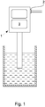
- Fig. 1 shows a field device 1 with a current output 2 and a located in the field device 1 control component 3.
- Field device 1 shown is a temperature measuring device with a temperature sensor, which is arranged in a container with a medium whose temperature is to be determined.
- Signal output 2 outputs current signals that contain information about the measured value.
- Output signals are read back from the field device 1, so that a desired current signal can be compared with an actual current signal.
- the control component 3 which acts when too large deviations. Depending on the magnitude of the deviation from the nominal current value to the actual current value, this can be different.
- the setpoint current value is adapted by the control component 3. At higher deviations, the control component 3 emits an acoustically and visually perceptible signal, which prompts the user to act, be it to repair or replace the field device 1.
- Fig. 2 shows the schematic sequence for an embodiment of the method for operating a field device.
- a measured value is generated by the field device. This can for example be the result of a level measurement, a speed measurement or other measurement of physical and / or chemical states.
- the measured value is then assigned in step 102 according to the known 4 ... 20 mA standard according to DIN IEC 60381-1 a current setpoint value, which is then output in step 103 as a target current signal.
- the signal output is designed as an analog current output.
- an actual current signal is read from the signal output and compared in step 105 with the desired current signal.
- the steps 102 to 105 are coordinated and performed by the control component of the field device.
- the signals are digitized at the same sampling rate to facilitate comparability at the digital level.
- a cross correlation of the desired current signal with the actual current signal is performed by the control component. Without further calculations, a deviation of the actual current signal from the nominal current signal alone can be calculated from the cross correlation as an absolute error.
- control component calculates an autocorrelation of the desired current signal and correlates the results of the cross-correlation with the results of the autocorrelation in order to determine a deviation.
- Fig. 3 is the schematic structure of a field device 1 for implementing the method according to Fig. 2 shown.
- the field device 1 comprises a conversion device 4, which converts the digital desired current signal into an analog signal after the generation of the desired current signal.
- the conversion device 4 is followed by an analog filter 5.
- This analog filter 5, here a low pass, has a cutoff frequency of 25 Hz.
- the filtered signal is then output via the signal output 2 and subsequently read back.
- the signal is digitized with an analog-to-digital converter 6, to allow easier evaluation and easier comparison with the desired current signal.
- a digital replica 7 of the analog filter 5 or the low-pass filter is provided the set nominal current signal filters.
- the desired current signal is tapped before the conversion device 4.
- Both signals, the digitally filtered nominal current signal and the read-back actual current signal, are subsequently compared by the control component 3 by calculating the cross-correlation, wherein they are fed to a computing unit 8.
Description
Die Erfindung betrifft ein Verfahren zum Betreiben eines Feldgerätes, wobei ein Messwert erzeugt wird und wobei dem Messwert ein Strom-Soll-Wert zugeordnet wird. Abhängig von dem Strom-Soll-Wert wird ein Soll-Strom-Signal ausgegeben. Ein Ist-Strom-Signal wird eingelesen und das Soll-Strom-Signal mit dem Ist-Strom-Signal verglichen. Darüber hinaus betrifft die Erfindung ein Feldgerät mit mindestens einem Signalausgang und mit mindestens einer Steuerkomponente. Das Feldgerät erzeugt einen Messwert und die Steuerkomponente ordnet dem Messwert einen Strom-Soll-Wert zu. Abhängig vom Strom-Soll-Wert erzeugt die Steuerkomponente ein Soll-Strom-Signal. Das Soll-Strom-Signal wird über den Signalausgang ausgegeben und die Steuerkomponente liest ein Ist-Strom-Signal ein. Die Steuerkomponente vergleicht das Soll-Strom-Signal mit dem Ist-Strom-Signal.The invention relates to a method for operating a field device, wherein a measured value is generated and wherein the measured value is assigned a desired current value. Depending on the current setpoint value, a setpoint current signal is output. An actual current signal is read in and the desired current signal is compared with the actual current signal. Moreover, the invention relates to a field device with at least one signal output and with at least one control component. The field device generates a measured value and the control component assigns a measured current value to the measured value. Depending on the desired current value, the control component generates a desired current signal. The desired current signal is output via the signal output and the control component reads in an actual current signal. The control component compares the desired current signal with the actual current signal.
Im Bereich der modernen Prozessautomatisierung werden zumeist Feldgeräte zur Überwachung von Prozessgrößen und Aktoren für die Beeinflussung der Prozesse verwendet. Für den Fall, dass es sich bei den Feldgeräten um Messgeräte handelt, die Füllstände, Durchflüsse, Temperaturen oder pH-Werte messen, entsprechen die vom Feldgerät ausgegebenen Signale jeweils den gewonnenen Messwerten. Über gegebenenfalls spezielle Ausgänge werden Signale ausgegeben, die auch Aussagen über den Zustand des Feldgerätes, beispielsweise Fehlersignale, übermitteln.In the field of modern process automation, field devices are mostly used for monitoring process variables and actuators for influencing the processes. In the event that the field devices are measuring devices that measure fill levels, flow rates, temperatures or pH values, the signals output by the field device correspond to the measured values obtained. If necessary, special outputs are used to output signals which also convey statements about the status of the field device, for example error signals.
Konventionell wird für die Signalisierung der Standard der 4...20 mA-Signale verwendet. Dabei werden Feldgeräte über 4...20mA Stromschleifen (Normsignal) mit einer übergeordneten Einheit verbunden bzw. an Regler und Steuerungen mit einem solchen Normalsignalausgang angeschlossen. Neben der Signalübertragung dienen diese Stromsignale bei der 2-Leiter-Technik der Energieversorgung der Feldgeräte. Für die Zuordnung von Signalen werden den beiden Grenzwerten von 4 mA und 20 mA meist der kleinste bzw. größte zu erwartende Messwert zugeordnet. Für die Messwerte, die dazwischen liegen, wird zumeist eine lineare Zuordnung vorgenommen. Im Falle eines im Feldgerät erkannten Fehlers werden standardgemäß Stromwerte außerhalb des Bereichs zwischen 4 mA und 20 mA ausgegeben.Conventionally, the standard of 4 ... 20 mA signals is used for signaling. Field devices are connected to a higher-level unit via 4 ... 20mA current loops (standard signal) or connected to controllers and controllers with such a standard signal output. In addition to the signal transmission, these current signals are used in the 2-wire technology to supply power to the field devices. For the assignment of signals, the two limit values of 4 mA and 20 mA are usually assigned the smallest or largest expected measured value. For the measured values that lie in between, a linear assignment is usually made. In case of im Field fault detected, current values outside the range between 4 mA and 20 mA are output by default.
Problematisch ist es, wenn das Feldgerät zwar einen Wert zwischen 4...20 mA ausgibt, dieser Wert aber fehlerhafterweise nicht dem eingestellten Wert entspricht, der dem korrespondierenden Messwert zugeordnet wurde.It is problematic if the field device outputs a value between 4 ... 20 mA, but erroneously this value does not correspond to the set value, which was assigned to the corresponding measured value.
Dazu ist es im Stand der Technik bekannt, dass ein vom Feldgerät ausgegebenes Strom-Signal rückgelesen und mit dem eingestellten Strom-Wert verglichen wird.For this purpose, it is known in the prior art that a current signal output by the field device is read back and compared with the set current value.
Die
Auf dem Gebiet der Übertragungsprotokolle werden beispielsweise Signale mit anderen Signalen überlagert oder gefiltert und sind so nur mit Mühe mit dem ursprünglich ausgegebenen Signal zu vergleichen.In the field of transmission protocols, for example, signals are superimposed or filtered with other signals and are thus difficult to compare with the originally output signal.
Ein Beispiel ist die weit verbreitete HART-Kommunikation. HART (Highway Adressable Remote Transducer) ist ein Protokoll für busadressierte Feldgeräte. Es ist eine Variante der digitalen Feldkommunikation, die viele Funktionalitäten von Feldbussen beinhaltet. Bei der HART-Kommunikation werden Feldgeräte konventionell nach dem 4...20mA-Standard angeschlossen und mit einer übergeordneten Einheit verbunden. Dem analogen 4...20mA-Signal wird im FSK Verfahren (Frequency Shift Keying) ein digitales Signal aufmoduliert. Somit können zusätzlich Mess-, Stell- und Gerätedaten übertragen werden, ohne das Analogsignal zu beeinflussen. Zusätzlich wird über das HART-Protokoll eine umfassende Integration der Feldgeräte in Prozessleitsysteme ermöglicht.An example is widespread HART communication. HART (Highway Addressable Remote Transducer) is a protocol for bus-addressed field devices. It is a variant of digital field communication, which includes many functionalities of fieldbuses. In HART communication, field devices are conventionally connected in accordance with the 4 ... 20mA standard and connected to a higher-level unit. The analogue 4 ... 20mA signal is modulated in FSK (Frequency Shift Keying) by a digital signal. Thus, additionally measuring, positioning and device data can be transmitted without affecting the analog signal. In addition, the HART protocol enables comprehensive integration of the field devices into process control systems.
Gerade bei dem bekannten HART-Standard, bei dem einem niederfrequenten, analogen Signal hochfrequente Signale überlagert werden, ist es üblich, dass ein analoger Tiefpass zur Bandbegrenzung verwendet wird. Dadurch werden höhere Frequenzen des 4...20 mA Signals ausgefiltert. Für den Fall, dass ungefilterte Signale mit einem hochfrequenten Signal nach dem HART-Standard überlagert werden, ist es schwierig, höhere Frequenzen eines breiten Frequenzspektrums von den hochfrequenten Überlagerungen zu unterscheiden. Durch die Verwendung eines analogen Tiefpasses wird die Kommunikation insgesamt vereinfacht.Especially in the known HART standard, in which a low-frequency, analog signal superimposed high-frequency signals, it is common that an analog low pass is used for band limitation. As a result, higher frequencies of the 4 ... 20 mA signal are filtered out. In the event that unfiltered signals are superimposed with a high-frequency signal according to the HART standard, it is difficult to distinguish higher frequencies of a broad frequency spectrum from the high-frequency superimpositions. The use of an analog low-pass filter simplifies the overall communication process.
Wird nun das Signal rückgelesen, muss das überlagerte Signal möglicherweise mit einem digitalen Filter entfernt werden. Durch die Umwandlung des analogen in ein digitales Signal und das analoge Filter treten zeitliche Verzögerungen zwischen den zu vergleichenden Signalen auf, die bei einem Vergleich der Signale berücksichtigt werden müssen.Now, if the signal is read back, the superimposed signal may need to be removed with a digital filter. The conversion of the analog to a digital signal and the analog filter time delays between the signals to be compared, which must be taken into account in a comparison of the signals.
Der Erfindung liegt daher die Aufgabe zugrunde, ein Verfahren zum Betreiben eines Feldgerätes - und ein entsprechendes Feldgerät - anzugeben, das eine zuverlässige Signalausgabe ermöglicht und dies insbesondere auch bei der Verwendung des HART-Protokolls.The invention is therefore based on the object of specifying a method for operating a field device-and a corresponding field device-which enables a reliable signal output and in particular also when using the HART protocol.
Das erfindungsgemäße Verfahren, bei dem die zuvor hergeleitete und aufgezeigte Aufgabe gelöst ist, ist zunächst und im Wesentlichen dadurch gekennzeichnet, dass für den Vergleich eine Kreuzkorrelation des Soll-Strom-Signals mit dem Ist-Strom-Signal gebildet wird. Durch die Kreuzkorrelation werden die Signale, auch wenn sie zeitlich verschoben sind, leicht und präzise vergleichbar.The inventive method, in which the previously derived and indicated object is achieved, is initially and essentially characterized in that for the comparison of a cross-correlation of the desired current signal is formed with the actual current signal. The cross-correlation allows the signals to be compared easily and precisely even if they are shifted in time.
Die Kreuzkorrelation ist definiert als das Integral über die Zeit zweier miteinander multiplizierten Zeitfunktionen x(t) und y(t), wobei eine der Funktionen zeitlich um einen festgelegten Wert τ zur anderen verschoben wird. Wenn nun beide Funktionen im Wesentlichen gleich sind, aber lediglich zeitlich um einen Wert τ1 verschoben sind, so wird die Korrelationsfunktion ein Maximum für τ=τ1 haben.The cross-correlation is defined as the integral over the time of two multiplied time functions x (t) and y (t), one of the functions being shifted in time by a fixed value τ to the other. Now, if both functions are substantially the same, but only temporally shifted by a value τ 1 , the correlation function will have a maximum for τ = τ 1 .
In der Praxis liegen Signale nicht als mathematische Funktionen, sondern als diskrete Zeitsignale vor, das heißt Werte xi, yi zu diskreten Zeitpunkten i=1...N. Somit ist es möglich, den Übergang des Integrals in eine Summe darzustellen (i entspricht t und k entspricht τ). Wird das Ergebnis durch den Effektivwert der einzelnen Signale dividiert, spricht man von einer normierten Kreuzkorrelation: 
Sind die Signale für ein k gleich, liefert die normierte Kreuzkorrelation den Wert 1. Sind die Signale gegenphasig, liefert sie den Wert -1. Von unkorrelierten Signalen spricht man, wenn der Wert der normierten Korrelation für alle k gleich Null ist.If the signals for a k are equal, the normalized cross-correlation returns the
Für die Auswertung und den Vergleich der ausgegebenen und rückgelesenen Signale bei dem erfindungsgemäßen Verfahren zum Betreiben eines Feldgerätes wird die Kreuzkorrelation verwendet. So ist es möglich, Signale zu vergleichen, die möglicherweise aufgrund von zeitlichen Verzögerungen durch Konvertierungen, Filtern oder sonstigen Maßnahmen zueinander versetzt sind. Darüber hinaus werden auch Signale, die nicht identisch sind oder sich nicht ähneln, effektiv verglichen, so dass das Ergebnis der Kreuzkorrelation Aussagen darüber erlaubt, ob ein Soll-Strom-Signal einem Ist-Strom-Signal entspricht.The cross-correlation is used for the evaluation and the comparison of the output and read-back signals in the method according to the invention for operating a field device. Thus, it is possible to compare signals that may be offset due to time delays due to conversions, filters or other measures. Moreover, even signals that are not identical or not similar are effectively compared, so that the result of the cross-correlation allows statements as to whether a desired current signal corresponds to an actual current signal.
Dadurch ist es bei diesem Verfahren möglich, dass Signalen andere Signale wie zum Beispiel Signale nach dem HART-Kommunikationsprotokoll überlagert werden. Auch bei nachträglichem Ausfiltern der HART-Signale für einen akkuraten Signalvergleich kann durch die Kreuzkorrelation ein zeitlicher Versatz der Signale zueinander, die ein solches Ausfiltern verursacht, ausgeglichen werden.This makes it possible with this method that signals other signals such as signals are superimposed on the HART communication protocol. Even if the HART signals are subsequently filtered out for an accurate signal comparison, the cross-correlation can compensate for a temporal offset of the signals to one another which causes such a filtering out.
In einer Ausgestaltung des erfindungsgemäßen Verfahrens ist es vorgesehen, dass eine Autokorrelation des Soll-Strom-Signals oder des Ist-Strom-Signals gebildet wird und dass eine Abweichung e der korrelierten Signale berechnet wird, wobei die Werte der Kreuzkorrelation des Ist-Strom-Signals mit dem Soll-Strom-Signal mit dem Wert der Autokorrelation des Strom-Soll-Wertes oder dem Wert der Autokorrelation des Ist-Strom-Signals zueinander ins Verhältnis gesetzt werden.In one embodiment of the method according to the invention, it is provided that an autocorrelation of the desired current signal or of the actual current signal is formed and that a deviation e of the correlated signals is calculated, wherein the values of the cross-correlation of the actual current signal with the Target current signal with the value of the autocorrelation of the current command value or the value of the autocorrelation of the actual current signal to each other in ratio be set.
Eine Autokorrelation einer Funktion oder eines Signals erhält man, wenn man ein Signal, wie oben beschrieben, mit sich selbst korreliert. Die Autokorrelation ist eine Art Selbstanalyse eines Signals und kann beispielsweise genutzt werden, um Periodizitäten in dem Signal aufzufinden.An autocorrelation of a function or signal is obtained by correlating a signal to itself as described above. The autocorrelation is a kind of self-analysis of a signal and can be used, for example, to find periodicities in the signal.
Bei dieser Ausgestaltung der Erfindung wird folglich eine relative Abweichung des Soll-Strom-Signals vom Ist-Strom-Signal bestimmt. Dabei kann zwischen der Autokorrelation des Soll-Strom-Signals und der Autokorrelation des Ist-Strom-Signals gewählt werden. Das Ergebnis der Kreuzkorrelation wird mit dem Ergebnis der Autokorrelation des Soll-Strom-Signals oder des Ist-Strom-Signals ins Verhältnis gesetzt. Je näher das Ergebnis der Division am Wert 1 liegt, desto ähnlicher sind sich folglich Soll-Strom-Signal und Ist-Strom-Signal. Prinzipiell muss sich das Verhältnis nicht auf eine Autokorrelation von Ist-Strom-Signal oder Soll-Strom-Signal beschränken.In this embodiment of the invention, consequently, a relative deviation of the desired current signal from the actual current signal is determined. In this case, it is possible to choose between the autocorrelation of the desired current signal and the autocorrelation of the actual current signal. The result of the cross-correlation is set in proportion to the result of autocorrelation of the target current signal or the actual current signal. The closer the result of the division is to the
Untersuchungen der Anmelderin haben ergeben, dass das Verfahren durch die Berechnung der Korrelationen selbst bei großen Transienten im Stromverlauf, ausgelöst beispielsweise von Stromstößen, noch zuverlässig arbeitet.Investigations by the Applicant have shown that the method still works reliably by calculating the correlations, even with large transients in the course of the current, for example caused by current surges.
Mit der ermittelten Abweichung e können andere Ereignisse oder Bedingungen verknüpft werden. Denkbar ist, dass ein erster vorgegebener Grenzwert nicht von der Abweichung e unterschritten und ein zweiter vorgegebener Grenzwert nicht überschritten werden darf. Bei Überschreiten der Grenzen kann ein Alarm ausgegeben werden und/oder eine Anpassung eines Signals erfolgen. Ein Alarm kann in optisch und/oder akustisch und/oder haptisch registrierbarer Form ausgegeben werden.With the determined deviation e other events or conditions can be linked. It is conceivable that a first predetermined limit value does not fall below the deviation e and a second predetermined limit value may not be exceeded. When the limits are exceeded, an alarm can be output and / or an adjustment of a signal can take place. An alarm can be issued in optically and / or acoustically and / or haptically recordable form.
In einer weiteren Ausgestaltung des erfindungsgemäßen Verfahrens ist vorgesehen, dass das Soll-Strom-Signal mit einer ersten Abtastrate und das Ist-Strom-Signal mit einer in einem festen Verhältnis zur ersten Abtastrate stehenden zweitenAbtastrate digitalisiert werden. In einer Ausgestaltung der Erfindung kann dieses Verhältnis auch gleich 1 gewählt werden, das heißt die Abtastraten sind gleich. Um den Vergleich der Signale zu vereinfachen, ist es vorteilhaft, wenn sie mit in festem Verhältnis zueinander stehenden Frequenzen abgetastet werden. Sowohl die Kreuzkorrelation als auch die Autokorrelation müssen nur über eine geringe Zahl von Abtastwerten berechnet werden, wodurch sich der Rechenaufwand pro Vergleich reduziert.In a further embodiment of the method according to the invention, it is provided that the desired current signal is digitized with a first sampling rate and the actual current signal with a second sampling rate that is at a fixed ratio to the first sampling rate. In one embodiment of the invention, this ratio can also be selected equal to 1, that is the Sampling rates are the same. To simplify the comparison of the signals, it is advantageous if they are sampled at fixed frequencies with each other. Both the cross-correlation and the autocorrelation need only be calculated over a small number of samples, which reduces the computational cost per comparison.
Die zuvor hergeleitete und aufgezeigte Aufgabe ist nach einer weiteren Lehre der Erfindung bei dem eingangs genannten Feldgerät dadurch gelöst, dass die Steuerkomponente für den Vergleich eine Kreuzkorrelation des Soll-Strom-Signals mit dem Ist-Strom-Signal bildet.The previously derived and indicated object is achieved according to a further teaching of the invention in the field device mentioned above in that the control component for the comparison forms a cross-correlation of the desired current signal with the actual current signal.
Bei dem Feldgerät handelt es sich insbesondere um einen Aktor oder ein Messgerät. Die Steuereinheit wird insbesondere verwendet, um ein Verfahren nach einem der Ansprüche 1 bis 3 durchzuführen. Die folgenden Ausführungen zu den Ausgestaltungen eines erfindungsgemäßen Feldgerätes gelten entsprechend auch für das bereits beschriebene Verfahren.The field device is in particular an actuator or a measuring device. The control unit is used in particular to perform a method according to one of
In einer Ausgestaltung des erfindungsgemäßen Feldgerätes ist es vorgesehen, dass eine Umwandlungseinrichtung zur Umwandlung von digitalen Signalen zu analogen Signalen, insbesondere ein Digital-Analog-Wandler oder eine Vorrichtung zur Pulsweitenmodulation, vorhanden ist und dass hinter der Umwandlungseinrichtung ein analoges Filter, vorzugsweise ein Tiefpass mit einer Grenzfrequenz kleiner oder gleich 25 Hz, geschaltet ist. Sowohl die Umwandlungseinrichtung als auch das analoge Filter sind vor dem Signalausgang geschaltet.In one embodiment of the field device according to the invention, it is provided that a conversion device for converting digital signals to analog signals, in particular a digital-to-analog converter or a device for pulse width modulation, is present and that behind the conversion means an analog filter, preferably a low-pass filter a cutoff frequency less than or equal to 25 Hz, is connected. Both the converter and the analog filter are connected in front of the signal output.
Wenn das Soll-Strom-Signal von der Steuerkomponente erzeugt wird, wird es im Anschluss zu einem analogen Signal umgesetzt und danach mit dem Tiefpass gefiltert, bevor es über den Signalausgang ausgegeben wird. Nach dem Tiefpass können dem analogen Signal noch andere Signale überlagert werden. Eine Überlagerung nach dem HART-Standard wäre zum Beispiel denkbar, so dass das Signal mit weiteren Informationen ausgestattet wird. Natürlich beschränkt sich dieser Vorgang nicht auf die HART-Kommunikation.When the desired current signal is generated by the control component, it is subsequently converted to an analog signal and then filtered with the low-pass filter before it is output via the signal output. After the low pass, other signals can be superimposed on the analog signal. An overlay according to the HART standard would be conceivable, for example, so that the signal is provided with further information. Of course, this process is not limited to HART communication.
Nach einer weiteren Ausgestaltung des erfindungsgemäßen Feldgerätes ist vorgesehen, dass ein Analog-Digital-Wandler vorhanden ist, der das eingelesene Ist-Strom-Signal digitalisiert.According to a further embodiment of the field device according to the invention it is provided that an analog-to-digital converter is present, which digitizes the read actual current signal.
Um das eingelesene Ist-Strom-Signal für die Steuerkomponente verarbeitbar zu machen, wird das rückgelesene Signal digitalisiert. Dabei kann, je nach Ausgestaltung, das Rücklesen direkt hinter dem Signalausgang realisiert werden oder aber an einer anderen Stelle, die das Signal passiert. Nach der Digitalisierung sind je nach Ausgestaltung weitere Bauteile eingebracht, die das Signal entsprechend bearbeiten. So kann ein digitales Filter verwendet werden, um ein gegebenenfalls vorhandenes HART-Signal auszufiltern. Dafür können FIR-Filter (Finite Impulse Response) verwendet werden.In order to make the read-in actual current signal for the control component processable, the read-back signal is digitized. In this case, depending on the configuration, the read back can be realized directly behind the signal output or at another point that passes the signal. After digitization, depending on the design, further components are introduced which process the signal accordingly. Thus, a digital filter can be used to filter out any HART signal that may be present. FIR filters (Finite Impulse Response) can be used for this.
In einer Ausgestaltung des erfindungsgemäßen Feldgerätes wird ein digitales Filter verwendet, um die hochfrequenten Überlagerungen eines vorhandenes HART-Signal auszufiltern. Bei der vorherigen Digitalisierung weist die Abtastrate des Ist-Strom-Signals eine höhere Frequenz auf als die Abtastrate des Soll-Strom-Signals. Vorteilhafterweise werden bei der höheren Abtastrate auch die hochfrequenten Signalanteile erfasst und diese werden anschließend digital ausgefiltert. Bei einer kleineren Abtastrate gehen die Informationen der hochfrequenten Signale verloren.In one embodiment of the field device according to the invention, a digital filter is used to filter out the high-frequency superimpositions of an existing HART signal. In the previous digitization, the sampling rate of the actual current signal has a higher frequency than the sampling rate of the desired current signal. Advantageously, at the higher sampling rate and the high-frequency signal components are detected and these are then filtered out digitally. At a lower sampling rate, the information of the high-frequency signals is lost.
In einem weiteren Ausführungsbeispiel des erfindungsgemäßen Feldgerätes ist vorgesehen, dass ein digitales Filter als funktionelle Nachbildung des analogen Filters, der der Umwandlungseinrichtung nachgeschaltet ist, vorhanden ist, wobei das digitale Filter das digitalisierte Soll-Strom-Signal filtert.In a further exemplary embodiment of the field device according to the invention, it is provided that a digital filter is present as a functional replica of the analog filter which is connected downstream of the conversion device, wherein the digital filter filters the digitized desired current signal.
Durch den digitalen Tiefpass wird das Soll-Strom-Signal an das Ist-Strom-Signal angeglichen. Ein zeitlicher Versatz, der durch zusätzliche Filter hervorgerufen wird, wird später bei der Durchführung der Kreuzkorrelation wieder ausgeglichen. Dennoch ist es sinnvoll, dass das Soll-Strom-Signal bereits vor der Umwandlungseinrichtung abgegriffen wird, damit gewährleistet wird, dass das Soll-Strom-Signal mit einem Ist-Strom-Signal verglichen wird und nicht mit einem Störsignal, das möglicherweise durch Übersprechen von unterschiedlichen Leitungen hervorgerufen wird.The digital low-pass filter matches the nominal current signal with the actual current signal. A temporal offset caused by additional filters will be compensated later in the cross correlation. Nevertheless, it makes sense that the desired current signal is tapped before the conversion device, so as to ensure that the target current signal is compared with an actual current signal and not with a noise signal, possibly by crosstalk from different lines is caused.
Wie zuvor im Einzelnen dargelegt, gibt es verschiedene Möglichkeiten, das erfindungsgemäße Verfahren zum Betreiben eines Feldgerätes beziehungsweise das erfindungsgemäße Feldgerät auszugestalten und weiterzubilden. Dazu wird verwiesen auf die den Patentansprüchen 1 und 4 nachgeordneten Patentansprüche und auf die nachfolgende Beschreibung von Ausführungsbeispielen in Verbindung mit der Zeichnung. In der Zeichnung zeigen
- Fig. 1
- eine schematische Darstellung eines Ausführungsbeispiels des Feldgerätes,
- Fig. 2
- eine schematische Darstellung einer Ausgestaltung des Verfahrens zum Betreiben eines Feldgerätes und
- Fig. 3
- eine schematische Darstellung des Aufbaus einer Ausgestaltung des Feldgerätes.
- Fig. 1
- a schematic representation of an embodiment of the field device,
- Fig. 2
- a schematic representation of an embodiment of the method for operating a field device and
- Fig. 3
- a schematic representation of the structure of an embodiment of the field device.
Die Signale werden mit der gleichen Abtastrate digitalisiert, um die Vergleichbarkeit auf digitaler Ebene zu vereinfachen. Bei dem Vergleich des Soll-Strom-Signals mit dem Ist-Strom-Signal wird von der Steuerkomponente eine Kreuzkorrelation des Soll-Strom-Signals mit dem Ist-Strom-Signal durchgeführt. Ohne weitere Berechnungen kann aus der Kreuzkorrelation allein also eine Abweichung des Ist-Strom-Signals vom Soll-Strom-Signal als absoluter Fehler berechnet werden.The signals are digitized at the same sampling rate to facilitate comparability at the digital level. In the comparison of the desired current signal with the actual current signal, a cross correlation of the desired current signal with the actual current signal is performed by the control component. Without further calculations, a deviation of the actual current signal from the nominal current signal alone can be calculated from the cross correlation as an absolute error.
In diesem Ausführungsbeispiel wird allerdings ein relativer Fehler bestimmt. Dazu berechnet die Steuerkomponente eine Autokorrelation des Soll-Strom-Signals und setzt die Ergebnisse der Kreuzkorrelation mit den Ergebnissen der Autokorrelation ins Verhältnis, um eine Abweichung zu ermitteln.In this embodiment, however, a relative error is determined. For this purpose, the control component calculates an autocorrelation of the desired current signal and correlates the results of the cross-correlation with the results of the autocorrelation in order to determine a deviation.
In
Das gefilterte Signal wird dann über den Signalausgang 2 ausgegeben und im Anschluss rückgelesen. Beim Rücklesen wird das Signal mit einem Analog-Digital-Wandler 6 digitalisiert, um eine einfachere Auswertung bzw. einen einfacheren Vergleich mit dem Soll-Strom-Signal zu ermöglichen.The filtered signal is then output via the
Damit die Signale besser miteinander verglichen werden können, ist eine digitale Nachbildung 7 des analogen Filters 5 bzw. des Tiefpasses vorgesehen, die das eingestellte Soll-Strom-Signal filtert. Das Soll-Strom-Signal wird vor der Umwandlungseinrichtung 4 abgegriffen. Beide Signale, das digital gefilterte Soll-Strom-Signal sowie das rückgelesene Ist-Strom-Signal, werden im Anschluss von der Steuerkomponente 3 durch Berechnung der Kreuzkorrelation verglichen, wobei sie einer Recheneinheit 8 zugeführt werden.So that the signals can be better compared with each other, a
Claims (8)
- Method for operating a field device (1), wherein a measured value is generated, wherein the measured value is assigned a current set point, wherein a target current signal is issued depending on the current set point, wherein an actual current signal is read back and the target current signal is compared to the actual current signal,
characterized in
that, a cross-correlation of the target current signal with the actual current signal is formed for comparison so that the target current signal and the actual current signal are easily and precisely comparable, even if they are temporally shifted. - Method according to claim 1, characterized in that an auto-correlation of the target current signal or of the actual current signal is formed and that a deviation (e) of the correlated signals is calculated in that the values of the cross-correlation of the actual current signal with the target current signal are put in relation to the value of the auto-correlation of the current set point or the value of the auto-correlation of the actual current signal.
- Method according to claim 1 or 2, characterized in that the target current signal is digitized with a first sampling rate and the actual current signal is digitized with a second sampling rate that is set at a fixed relation to the first sampling rate.
- Field device (1) having at least one signal outlet (2) and at least one control component (3), wherein the field device (1) generates a measured value, wherein the control component (3) assigns the measured value a current set point, generates a target current signal depending on the current set point and issues the target current signal via the signal outlet (2) and wherein the control component (3) reads an actual current signal back and compares the target current signal to the actual current signal,
characterized in
that the control component (3) forms a cross-correlation of the target current signal with the actual current signal for comparison so that the target current signal and the actual current signal are easily and precisely comparable, even if they are temporally shifted. - Field device (1) according to claim 4, characterized in that a converting device (4), in particular a digital-to-analog converter or a device for pulse width modulation, is provided for conversion from digital signals to analog signals.
- Field device (1) according to claim 5, characterized in that an analog filter (5), preferably a low pass filter having a limit frequency less than or equal to 25 Hz, is connected behind the converting device (4).
- Field device (1) according to claim 6, characterized in that a digital filter (7) is provided as functional replication of the analog filter (5), wherein the digital filter (7) filters the target current signal.
- Field device (1) according to any one of claims 4 to 7, characterized in that an analog-to-digital converter (6) is provided that digitizes the imported actual current signal.
Applications Claiming Priority (1)
| Application Number | Priority Date | Filing Date | Title |
|---|---|---|---|
| DE102015105090.0A DE102015105090A1 (en) | 2015-04-01 | 2015-04-01 | Method for operating a field device and corresponding field device |
Publications (2)
| Publication Number | Publication Date |
|---|---|
| EP3076249A1 EP3076249A1 (en) | 2016-10-05 |
| EP3076249B1 true EP3076249B1 (en) | 2019-04-10 |
Family
ID=55349710
Family Applications (1)
| Application Number | Title | Priority Date | Filing Date |
|---|---|---|---|
| EP16154999.3A Active EP3076249B1 (en) | 2015-04-01 | 2016-02-10 | Method for operating a field device and corresponding field device |
Country Status (4)
| Country | Link |
|---|---|
| US (1) | US10044348B2 (en) |
| EP (1) | EP3076249B1 (en) |
| CN (1) | CN106052721B (en) |
| DE (1) | DE102015105090A1 (en) |
Family Cites Families (25)
| Publication number | Priority date | Publication date | Assignee | Title |
|---|---|---|---|---|
| JPS6398265A (en) * | 1986-10-14 | 1988-04-28 | Fujitsu Ltd | Phase difference detecting method |
| RU2079852C1 (en) * | 1995-03-14 | 1997-05-20 | Калининградское высшее инженерное училище инженерных войск | Method of evaluation of coefficient of nonsinusoidal character of voltage curve |
| US6466893B1 (en) * | 1997-09-29 | 2002-10-15 | Fisher Controls International, Inc. | Statistical determination of estimates of process control loop parameters |
| DE19930661A1 (en) | 1999-07-02 | 2001-01-18 | Siemens Ag | Transmitter |
| US6557131B1 (en) * | 1999-12-23 | 2003-04-29 | Cirrus Logic, Inc. | Apparatus and method for automated testing of integrated analog to digital converters |
| KR100397055B1 (en) * | 2000-07-21 | 2003-09-06 | (주)씨앤에스 테크놀로지 | Motion estimator architecture for low bit rate image communication |
| KR100505678B1 (en) * | 2003-03-17 | 2005-08-03 | 삼성전자주식회사 | Orthogonal Frequency Division Multiplexor transceiving unit of wireless Local Area Network system providing for symbol timing synchronization by double correlation and double peak comparison and symbol timing synchronization method thereof |
| US7280048B2 (en) * | 2003-08-07 | 2007-10-09 | Rosemount Inc. | Process control loop current verification |
| DE102004019392A1 (en) * | 2004-04-19 | 2005-12-08 | Endress + Hauser Gmbh + Co. Kg | Digital transmitter with current signal |
| BRPI0610522A2 (en) * | 2005-04-04 | 2017-01-31 | Fisher Rosemount Systems Inc | methods for detecting an abnormal situation associated with a process facility, an abnormal situation in a fluid catalytic cracker and a distillation column, for processing data collected in a process facility, and for adapting a sine wave to data collected within a process installation |
| US7538570B2 (en) * | 2005-04-25 | 2009-05-26 | Nxp B.V. | Supply voltage monitoring |
| US7272518B2 (en) * | 2005-07-01 | 2007-09-18 | Square D Company | Automated hierarchy classification in utility monitoring systems |
| JP2007323449A (en) * | 2006-06-02 | 2007-12-13 | Hitachi High-Tech Control Systems Corp | Transmitter system |
| DE102007059847A1 (en) * | 2007-12-12 | 2009-06-18 | Siemens Ag | Field device for process instrumentation |
| GB0803710D0 (en) * | 2008-02-28 | 2008-04-09 | Nokia Corp | DC compensation |
| CN101241151B (en) * | 2008-02-28 | 2010-09-15 | 江苏省电力试验研究院有限公司 | Real time frequency measurement method based on amplitude linear change model |
| JP5041293B2 (en) * | 2008-05-30 | 2012-10-03 | 富士電機株式会社 | Magnetic recording medium evaluation apparatus and evaluation method thereof |
| DE102008050354A1 (en) * | 2008-10-02 | 2010-04-08 | Siemens Aktiengesellschaft | transmitters |
| US7961125B2 (en) * | 2008-10-23 | 2011-06-14 | Microchip Technology Incorporated | Method and apparatus for dithering in multi-bit sigma-delta digital-to-analog converters |
| CN101738240B (en) * | 2008-11-27 | 2013-01-23 | 苟阳明 | Capacitance sensing type fuel meter |
| US8737941B2 (en) * | 2010-03-30 | 2014-05-27 | Skyworks Solutions, Inc. | Gain control systems and methods for controlling an adjustable power level |
| CN101931765B (en) * | 2010-08-11 | 2013-03-13 | 无锡辐导微电子有限公司 | Broadband tuner based on band pass sigma-delta modulation and method thereof |
| CN102768316B (en) * | 2012-08-01 | 2015-04-08 | 东北农业大学 | Switching mutual inductance value measurement method used in discharging process of constant-current source charging diodes |
| KR102103933B1 (en) * | 2013-09-04 | 2020-04-24 | 삼성전자주식회사 | Successive approximation analog to digital converter and method of analog to digital conversion |
| KR102305356B1 (en) * | 2014-12-18 | 2021-09-28 | 삼성디스플레이 주식회사 | Display device and electronic device having the same |
-
2015
- 2015-04-01 DE DE102015105090.0A patent/DE102015105090A1/en not_active Withdrawn
-
2016
- 2016-02-10 EP EP16154999.3A patent/EP3076249B1/en active Active
- 2016-03-31 US US15/086,301 patent/US10044348B2/en active Active
- 2016-04-01 CN CN201610198625.2A patent/CN106052721B/en active Active
Non-Patent Citations (1)
| Title |
|---|
| None * |
Also Published As
| Publication number | Publication date |
|---|---|
| US20160294375A1 (en) | 2016-10-06 |
| DE102015105090A1 (en) | 2016-10-06 |
| EP3076249A1 (en) | 2016-10-05 |
| US10044348B2 (en) | 2018-08-07 |
| CN106052721B (en) | 2021-09-21 |
| CN106052721A (en) | 2016-10-26 |
Similar Documents
| Publication | Publication Date | Title |
|---|---|---|
| EP2425308B1 (en) | Device and method for the residual analysis of a residuum to detect system errors in the system behavior of an aircraft | |
| DE19983112B3 (en) | Signal processing technique that separates signal components in a sensor signal for signal diagnosis | |
| EP3234512B1 (en) | Differential pressure type flowmeter | |
| EP2494313B1 (en) | Field device for process instrumentation | |
| DE102016117944A1 (en) | Servo control system with function for measuring a property of a learning controller | |
| EP2701018B1 (en) | Method for securely adjusting the parameters of a field device | |
| WO2016165928A1 (en) | Method for automatically connecting or disconnecting a communication resistor of a hart device | |
| DE102006024742A1 (en) | transmitters | |
| EP3995790A2 (en) | Flowmeter, method for operating a flowmeter, installation and method for operating an installation | |
| EP3377861A1 (en) | Method for the in situ calibration of an analog measurement transmission path, and corresponding device | |
| EP2072964A2 (en) | Method and device for calculating measurement values from a time-dependent process | |
| EP3076249B1 (en) | Method for operating a field device and corresponding field device | |
| WO2016026620A1 (en) | Method for checking a field device | |
| DE102012106375A1 (en) | Method and device for diagnosing a communication channel | |
| DE102012109132B4 (en) | Improved method and device for avoiding aliasing | |
| DE102014009354A1 (en) | Method and device for error analysis of a measuring device | |
| EP2250538A1 (en) | Method for the visual display of the quality of power transmitted on a power transmission system | |
| DE102014009709A1 (en) | Method for analog transmission of a sensor signal | |
| WO2018028931A1 (en) | Differential pressure measurement arrangement and method for identifying blocked differential pressure lines | |
| EP3084359B1 (en) | Process and assembly for differential pressure measurements with zero-point calibration | |
| EP3404430B1 (en) | Method for monitoring an operation of a binary interface and related binary interface | |
| EP3019828B1 (en) | Measuring transducer for converting an analogue electrical input signal into an analog electrical output signal | |
| DE102010064205A1 (en) | Method for checking e.g. validity of periodic analog signal transmitted from e.g. measuring device to evaluation unit, involves producing statement about e.g. validity of signal, with reference to maximum of correlation value | |
| EP2027516A1 (en) | Field device and method for processing at least one measured variable in a field device | |
| EP1609031B1 (en) | Field device for determining in advance the point in time of a measurement |
Legal Events
| Date | Code | Title | Description |
|---|---|---|---|
| PUAI | Public reference made under article 153(3) epc to a published international application that has entered the european phase |
Free format text: ORIGINAL CODE: 0009012 |
|
| AK | Designated contracting states |
Kind code of ref document: A1 Designated state(s): AL AT BE BG CH CY CZ DE DK EE ES FI FR GB GR HR HU IE IS IT LI LT LU LV MC MK MT NL NO PL PT RO RS SE SI SK SM TR |
|
| AX | Request for extension of the european patent |
Extension state: BA ME |
|
| STAA | Information on the status of an ep patent application or granted ep patent |
Free format text: STATUS: REQUEST FOR EXAMINATION WAS MADE |
|
| STAA | Information on the status of an ep patent application or granted ep patent |
Free format text: STATUS: EXAMINATION IS IN PROGRESS |
|
| 17P | Request for examination filed |
Effective date: 20170405 |
|
| RBV | Designated contracting states (corrected) |
Designated state(s): AL AT BE BG CH CY CZ DE DK EE ES FI FR GB GR HR HU IE IS IT LI LT LU LV MC MK MT NL NO PL PT RO RS SE SI SK SM TR |
|
| 17Q | First examination report despatched |
Effective date: 20170503 |
|
| GRAP | Despatch of communication of intention to grant a patent |
Free format text: ORIGINAL CODE: EPIDOSNIGR1 |
|
| STAA | Information on the status of an ep patent application or granted ep patent |
Free format text: STATUS: GRANT OF PATENT IS INTENDED |
|
| INTG | Intention to grant announced |
Effective date: 20180914 |
|
| GRAS | Grant fee paid |
Free format text: ORIGINAL CODE: EPIDOSNIGR3 |
|
| GRAA | (expected) grant |
Free format text: ORIGINAL CODE: 0009210 |
|
| STAA | Information on the status of an ep patent application or granted ep patent |
Free format text: STATUS: THE PATENT HAS BEEN GRANTED |
|
| AK | Designated contracting states |
Kind code of ref document: B1 Designated state(s): AL AT BE BG CH CY CZ DE DK EE ES FI FR GB GR HR HU IE IS IT LI LT LU LV MC MK MT NL NO PL PT RO RS SE SI SK SM TR |
|
| REG | Reference to a national code |
Ref country code: GB Ref legal event code: FG4D Free format text: NOT ENGLISH |
|
| REG | Reference to a national code |
Ref country code: CH Ref legal event code: EP Ref country code: AT Ref legal event code: REF Ref document number: 1119545 Country of ref document: AT Kind code of ref document: T Effective date: 20190415 |
|
| REG | Reference to a national code |
Ref country code: IE Ref legal event code: FG4D Free format text: LANGUAGE OF EP DOCUMENT: GERMAN |
|
| REG | Reference to a national code |
Ref country code: DE Ref legal event code: R096 Ref document number: 502016004065 Country of ref document: DE |
|
| REG | Reference to a national code |
Ref country code: NL Ref legal event code: FP |
|
| REG | Reference to a national code |
Ref country code: LT Ref legal event code: MG4D |
|
| PG25 | Lapsed in a contracting state [announced via postgrant information from national office to epo] |
Ref country code: ES Free format text: LAPSE BECAUSE OF FAILURE TO SUBMIT A TRANSLATION OF THE DESCRIPTION OR TO PAY THE FEE WITHIN THE PRESCRIBED TIME-LIMIT Effective date: 20190410 Ref country code: SE Free format text: LAPSE BECAUSE OF FAILURE TO SUBMIT A TRANSLATION OF THE DESCRIPTION OR TO PAY THE FEE WITHIN THE PRESCRIBED TIME-LIMIT Effective date: 20190410 Ref country code: FI Free format text: LAPSE BECAUSE OF FAILURE TO SUBMIT A TRANSLATION OF THE DESCRIPTION OR TO PAY THE FEE WITHIN THE PRESCRIBED TIME-LIMIT Effective date: 20190410 Ref country code: NO Free format text: LAPSE BECAUSE OF FAILURE TO SUBMIT A TRANSLATION OF THE DESCRIPTION OR TO PAY THE FEE WITHIN THE PRESCRIBED TIME-LIMIT Effective date: 20190710 Ref country code: AL Free format text: LAPSE BECAUSE OF FAILURE TO SUBMIT A TRANSLATION OF THE DESCRIPTION OR TO PAY THE FEE WITHIN THE PRESCRIBED TIME-LIMIT Effective date: 20190410 Ref country code: PT Free format text: LAPSE BECAUSE OF FAILURE TO SUBMIT A TRANSLATION OF THE DESCRIPTION OR TO PAY THE FEE WITHIN THE PRESCRIBED TIME-LIMIT Effective date: 20190910 Ref country code: LT Free format text: LAPSE BECAUSE OF FAILURE TO SUBMIT A TRANSLATION OF THE DESCRIPTION OR TO PAY THE FEE WITHIN THE PRESCRIBED TIME-LIMIT Effective date: 20190410 Ref country code: HR Free format text: LAPSE BECAUSE OF FAILURE TO SUBMIT A TRANSLATION OF THE DESCRIPTION OR TO PAY THE FEE WITHIN THE PRESCRIBED TIME-LIMIT Effective date: 20190410 |
|
| PG25 | Lapsed in a contracting state [announced via postgrant information from national office to epo] |
Ref country code: RS Free format text: LAPSE BECAUSE OF FAILURE TO SUBMIT A TRANSLATION OF THE DESCRIPTION OR TO PAY THE FEE WITHIN THE PRESCRIBED TIME-LIMIT Effective date: 20190410 Ref country code: LV Free format text: LAPSE BECAUSE OF FAILURE TO SUBMIT A TRANSLATION OF THE DESCRIPTION OR TO PAY THE FEE WITHIN THE PRESCRIBED TIME-LIMIT Effective date: 20190410 Ref country code: BG Free format text: LAPSE BECAUSE OF FAILURE TO SUBMIT A TRANSLATION OF THE DESCRIPTION OR TO PAY THE FEE WITHIN THE PRESCRIBED TIME-LIMIT Effective date: 20190710 Ref country code: GR Free format text: LAPSE BECAUSE OF FAILURE TO SUBMIT A TRANSLATION OF THE DESCRIPTION OR TO PAY THE FEE WITHIN THE PRESCRIBED TIME-LIMIT Effective date: 20190711 Ref country code: PL Free format text: LAPSE BECAUSE OF FAILURE TO SUBMIT A TRANSLATION OF THE DESCRIPTION OR TO PAY THE FEE WITHIN THE PRESCRIBED TIME-LIMIT Effective date: 20190410 |
|
| PG25 | Lapsed in a contracting state [announced via postgrant information from national office to epo] |
Ref country code: IS Free format text: LAPSE BECAUSE OF FAILURE TO SUBMIT A TRANSLATION OF THE DESCRIPTION OR TO PAY THE FEE WITHIN THE PRESCRIBED TIME-LIMIT Effective date: 20190810 |
|
| REG | Reference to a national code |
Ref country code: DE Ref legal event code: R097 Ref document number: 502016004065 Country of ref document: DE |
|
| PG25 | Lapsed in a contracting state [announced via postgrant information from national office to epo] |
Ref country code: EE Free format text: LAPSE BECAUSE OF FAILURE TO SUBMIT A TRANSLATION OF THE DESCRIPTION OR TO PAY THE FEE WITHIN THE PRESCRIBED TIME-LIMIT Effective date: 20190410 Ref country code: DK Free format text: LAPSE BECAUSE OF FAILURE TO SUBMIT A TRANSLATION OF THE DESCRIPTION OR TO PAY THE FEE WITHIN THE PRESCRIBED TIME-LIMIT Effective date: 20190410 Ref country code: RO Free format text: LAPSE BECAUSE OF FAILURE TO SUBMIT A TRANSLATION OF THE DESCRIPTION OR TO PAY THE FEE WITHIN THE PRESCRIBED TIME-LIMIT Effective date: 20190410 Ref country code: SK Free format text: LAPSE BECAUSE OF FAILURE TO SUBMIT A TRANSLATION OF THE DESCRIPTION OR TO PAY THE FEE WITHIN THE PRESCRIBED TIME-LIMIT Effective date: 20190410 Ref country code: CZ Free format text: LAPSE BECAUSE OF FAILURE TO SUBMIT A TRANSLATION OF THE DESCRIPTION OR TO PAY THE FEE WITHIN THE PRESCRIBED TIME-LIMIT Effective date: 20190410 |
|
| PLBE | No opposition filed within time limit |
Free format text: ORIGINAL CODE: 0009261 |
|
| STAA | Information on the status of an ep patent application or granted ep patent |
Free format text: STATUS: NO OPPOSITION FILED WITHIN TIME LIMIT |
|
| PG25 | Lapsed in a contracting state [announced via postgrant information from national office to epo] |
Ref country code: SM Free format text: LAPSE BECAUSE OF FAILURE TO SUBMIT A TRANSLATION OF THE DESCRIPTION OR TO PAY THE FEE WITHIN THE PRESCRIBED TIME-LIMIT Effective date: 20190410 Ref country code: IT Free format text: LAPSE BECAUSE OF FAILURE TO SUBMIT A TRANSLATION OF THE DESCRIPTION OR TO PAY THE FEE WITHIN THE PRESCRIBED TIME-LIMIT Effective date: 20190410 |
|
| 26N | No opposition filed |
Effective date: 20200113 |
|
| PG25 | Lapsed in a contracting state [announced via postgrant information from national office to epo] |
Ref country code: TR Free format text: LAPSE BECAUSE OF FAILURE TO SUBMIT A TRANSLATION OF THE DESCRIPTION OR TO PAY THE FEE WITHIN THE PRESCRIBED TIME-LIMIT Effective date: 20190410 |
|
| PG25 | Lapsed in a contracting state [announced via postgrant information from national office to epo] |
Ref country code: SI Free format text: LAPSE BECAUSE OF FAILURE TO SUBMIT A TRANSLATION OF THE DESCRIPTION OR TO PAY THE FEE WITHIN THE PRESCRIBED TIME-LIMIT Effective date: 20190410 |
|
| REG | Reference to a national code |
Ref country code: BE Ref legal event code: MM Effective date: 20200229 |
|
| PG25 | Lapsed in a contracting state [announced via postgrant information from national office to epo] |
Ref country code: LU Free format text: LAPSE BECAUSE OF NON-PAYMENT OF DUE FEES Effective date: 20200210 Ref country code: MC Free format text: LAPSE BECAUSE OF FAILURE TO SUBMIT A TRANSLATION OF THE DESCRIPTION OR TO PAY THE FEE WITHIN THE PRESCRIBED TIME-LIMIT Effective date: 20190410 |
|
| PG25 | Lapsed in a contracting state [announced via postgrant information from national office to epo] |
Ref country code: IE Free format text: LAPSE BECAUSE OF NON-PAYMENT OF DUE FEES Effective date: 20200210 |
|
| PG25 | Lapsed in a contracting state [announced via postgrant information from national office to epo] |
Ref country code: BE Free format text: LAPSE BECAUSE OF NON-PAYMENT OF DUE FEES Effective date: 20200229 |
|
| REG | Reference to a national code |
Ref country code: AT Ref legal event code: MM01 Ref document number: 1119545 Country of ref document: AT Kind code of ref document: T Effective date: 20210210 |
|
| PG25 | Lapsed in a contracting state [announced via postgrant information from national office to epo] |
Ref country code: AT Free format text: LAPSE BECAUSE OF NON-PAYMENT OF DUE FEES Effective date: 20210210 |
|
| PG25 | Lapsed in a contracting state [announced via postgrant information from national office to epo] |
Ref country code: MT Free format text: LAPSE BECAUSE OF FAILURE TO SUBMIT A TRANSLATION OF THE DESCRIPTION OR TO PAY THE FEE WITHIN THE PRESCRIBED TIME-LIMIT Effective date: 20190410 Ref country code: CY Free format text: LAPSE BECAUSE OF FAILURE TO SUBMIT A TRANSLATION OF THE DESCRIPTION OR TO PAY THE FEE WITHIN THE PRESCRIBED TIME-LIMIT Effective date: 20190410 |
|
| PG25 | Lapsed in a contracting state [announced via postgrant information from national office to epo] |
Ref country code: MK Free format text: LAPSE BECAUSE OF FAILURE TO SUBMIT A TRANSLATION OF THE DESCRIPTION OR TO PAY THE FEE WITHIN THE PRESCRIBED TIME-LIMIT Effective date: 20190410 |
|
| PGFP | Annual fee paid to national office [announced via postgrant information from national office to epo] |
Ref country code: NL Payment date: 20230216 Year of fee payment: 8 |
|
| PGFP | Annual fee paid to national office [announced via postgrant information from national office to epo] |
Ref country code: FR Payment date: 20230221 Year of fee payment: 8 Ref country code: CH Payment date: 20230307 Year of fee payment: 8 |
|
| PGFP | Annual fee paid to national office [announced via postgrant information from national office to epo] |
Ref country code: GB Payment date: 20230221 Year of fee payment: 8 |
|
| P01 | Opt-out of the competence of the unified patent court (upc) registered |
Effective date: 20230607 |
|
| PGFP | Annual fee paid to national office [announced via postgrant information from national office to epo] |
Ref country code: DE Payment date: 20230420 Year of fee payment: 8 |
|
| PGFP | Annual fee paid to national office [announced via postgrant information from national office to epo] |
Ref country code: NL Payment date: 20240219 Year of fee payment: 9 |