EP3377428B1 - Widerlagervorrichtung - Google Patents
Widerlagervorrichtung Download PDFInfo
- Publication number
- EP3377428B1 EP3377428B1 EP16794680.5A EP16794680A EP3377428B1 EP 3377428 B1 EP3377428 B1 EP 3377428B1 EP 16794680 A EP16794680 A EP 16794680A EP 3377428 B1 EP3377428 B1 EP 3377428B1
- Authority
- EP
- European Patent Office
- Prior art keywords
- stop
- lever
- stop member
- holding
- rotation
- Prior art date
- Legal status (The legal status is an assumption and is not a legal conclusion. Google has not performed a legal analysis and makes no representation as to the accuracy of the status listed.)
- Active
Links
Images

Classifications
-
- B—PERFORMING OPERATIONS; TRANSPORTING
- B65—CONVEYING; PACKING; STORING; HANDLING THIN OR FILAMENTARY MATERIAL
- B65G—TRANSPORT OR STORAGE DEVICES, e.g. CONVEYORS FOR LOADING OR TIPPING, SHOP CONVEYOR SYSTEMS OR PNEUMATIC TUBE CONVEYORS
- B65G47/00—Article or material-handling devices associated with conveyors; Methods employing such devices
- B65G47/74—Feeding, transfer, or discharging devices of particular kinds or types
- B65G47/88—Separating or stopping elements, e.g. fingers
- B65G47/8807—Separating or stopping elements, e.g. fingers with one stop
- B65G47/8823—Pivoting stop, swinging in or out of the path of the article
Definitions
- the present invention relates to a stop device.
- the movable stops are controlled by a pneumatic circuit.
- the present invention aims to provide a simple movable stop device, which can withstand significant mechanical forces while consuming little energy.
- the lever comprises a holding portion configured to cooperate with a bearing surface of the stop member, so that in the holding position the lever holding portion is engaged against the bearing surface of the member stop outside the plane defined by the axes of rotation of the lever and of the stop, and in the release position the holding portion is spaced from the stop member, the lever further comprising a pusher member configured to exert a force on the chassis to hold the lever in the position for holding the member stop.
- the invention provides a mobile abutment device of simple structure, which can withstand significant mechanical forces while consuming little energy.
- the stop device in the holding position, has a self-locking articulation which guarantees the blocking in the stop position of the stop member.
- the device according to the invention can therefore withstand significant mechanical forces, without consuming energy to keep the stop member in position.
- the device according to the invention uses electrical energy only to move the stop member into the retracted position.
- the pusher member comprises a finger urged by a compression spring.
- the lever may include a follower portion configured to cooperate with the control cam to move the lever into the release position.
- the stop member may have a spout configured so that when the lever is in the release position, the stop member goes into the retracted position.
- the lever may have a recess configured to receive the spout when the stop member is in the retracted position.
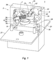
- the invention provides a stop device 1 shown in the Figures 1 to 3 .
- the stop device 1 has a frame 2.
- the frame 2 has a parallelepiped geometry.
- Chassis 2 has two fins 21 for fixing the frame 2, for example, to a conveyor.
- the chassis 2 has a chamber 24.
- the chamber 24 includes a lumen 25 opening onto an upper surface 26 of the chassis 2.
- a stop member 5, a lever 7 and a control cam 9 are positioned in the chamber 24.
- the abutment member 5 has a general hammer shape with: an abutment surface 51, a spout 52 and an arm 53.
- the arm 53 of the stop member 5 is pivotally connected to the chassis 2, so that the stop member 5 is movable between a stop position and a retracted position. In the stop position, the stop surface 51 emerges from the opening 25 in the chamber 24. In the retracted position, the stop member 5 is entirely contained in the chamber 24.
- the abutment member 5 has a bearing surface 55 formed along the arm 53, facing the spout 52. According to the embodiment shown here, the bearing surface 55 includes a fillet between the arm 53 and the spout 52.
- the spout 52 has a geometry suitable for passing the stop member 5 into the retracted position, when no force is applied to the stop member 5.
- the lever 7 has a bent geometry with two ends.
- a first end of the lever 7 has a holding portion 71 adapted to slide and press on the bearing surface 55.
- the lever 7 has a recess 73 configured to receive the spout 52 of the stop member 5 when the stop member 2 is in the retracted position.
- a second end of the lever 7 has a follower portion 75 configured to cooperate with the control cam 9.
- the lever 7 has a blind hole 76.
- the bent portion of the lever 7 is pivotally connected to the chassis 2, so that the lever 7 is movable between a holding position and a release position.
- a pusher member 8 is positioned in the blind hole 76.
- the pusher member 8 comprises a finger 81 urged by a compression spring 82 whose function will be detailed below.
- the control cam 9 is positioned opposite the follower portion 75, so as to be able to exert a force on the follower portion 75.
- the control cam 9 is controlled by an electric motor 92 connected to the chassis 2.
- the electric motor 92 is a brushless servomotor.
- the figure 2 presents the stop device 1 when the stop member 5 is in the stop position.
- the lever 7 is held by the finger 81, in its holding position.
- the stop member 5 is held in the stop position.
- the finger 81 partially emerges from the blind hole 76 and presses against the frame 2 so that the holding portion 71 exerts a force on the bearing surface 55.
- the force exerted by the holding portion 71 makes it possible to hold the member stop 5 in the stop position.
- the stop member 5 is then no longer held in its stop position so that an object - pallet or other package - circulating on a conveyor equipped with the stop device according to the invention 1 naturally erases the conveyor for the put in its retracted position.
- the spout 52 In the retracted position, the spout 52 is positioned in the recess 73 and the stop member 5 passes into the retracted position.
- the transition from the retracted position to the stop position is achieved by a simple relaxation of the force exerted by the cam 9 on the follower portion 75.
- the pushing force of the finger 81, on the chassis 2 is sufficient to cause the lever 7 to pass into the holding position and the member 5 to the stop position.
- the invention provides a stop device controlled by electrical energy efficient.
- the architecture of the stop device 1 makes it possible to guarantee locking in the stop position, without it being necessary to maintain the electrical supply of the cam, or to use a particularly stiff spring to stress the finger 81
- This arrangement thus makes it possible to use an electric motor of reduced power such as for example, an electric motor supplied with an adjustable voltage situated between 4 and 6 V.
- the architecture of the stop device 1 allows the stop device 1 to have reduced dimensions which allow, for example, its integration between two transfer strands 40 mm apart.
Landscapes
- Engineering & Computer Science (AREA)
- Mechanical Engineering (AREA)
- Special Conveying (AREA)
Claims (5)
- Anschlagvorrichtung (1), die ein Gestell (2) aufweist, umfassend:(i) ein Anschlagelement (5), das zwischen einer Anschlagposition und einer zurückgezogenen Position drehbar ist,(ii) einen Hebel (7), der zwischen einer Position zum Halten des Anschlagelements (5) und einer Position zum Freigeben des Anschlagelements (5) drehbar ist, wodurch das Anschlagelement (5) in die zurückgezogene Position übergehen kann, und(iii) einen Steuernocken (9), der von einem Elektromotor in Drehung versetzt wird, wobei der Steuernocken (9) so ausgestaltet ist, dass er den Hebel (7) von der Halteposition in die Freigabeposition übergehen lässt,
wobei der Hebel (7) einen Halteabschnitt (71) umfasst, der ausgestaltet ist, mit einer Auflagefläche (55) des Anschlagelements (5) zusammenzuwirken, sodass in der Halteposition der Halteabschnitt (71) des Hebels (7) gegen die Auflagefläche (55) des Anschlagelements (5) außerhalb der Ebene drückt, die von den Drehachsen des Hebels (7) und des Anschlagelements (5) definiert wird, und in der Freigabeposition der Halteabschnitt (71) von dem Anschlagelement (5) beabstandet ist, dadurch gekennzeichnet, dass der Hebel (7) des Weiteren ein Druckelement (8) umfasst, das ausgestaltet ist, eine Kraft auf das Gestell auszuüben, um den Hebel (7) in der Position zum Halten des Anschlagelements (5) zu halten. - Anschlagvorrichtung (1) nach Anspruch 1, dadurch gekennzeichnet, dass das Druckelement (8) mindestens einen Finger (81) umfasst, der durch eine Feder (82) beansprucht wird.
- Anschlagvorrichtung (1) nach einem der Ansprüche 1 bis 2, dadurch gekennzeichnet, dass der Hebel (7) einen Nachlaufabschnitt (75) umfasst, der ausgestaltet ist, mit dem Steuernocken (9) zusammenzuwirken, um den Hebel (7) in die Freigabeposition übergehen zu lassen.
- Anschlagvorrichtung (1) nach einem der Ansprüche 1 bis 3, dadurch gekennzeichnet, dass das Anschlagelement (5) eine Spitze (52) aufweist, die ausgestaltet ist, damit das Anschlagelement (5), wenn sich der Hebel (7) in der Freigabeposition befindet, in die zurückgezogene Position übergeht.
- Anschlagvorrichtung (1) nach Anspruch 4, dadurch gekennzeichnet, dass der Hebel (7) eine Aussparung (73) aufweist, die ausgestaltet ist, die Spitze (52) aufzunehmen, wenn sich das Anschlagelement (5) in der zurückgezogenen Position befindet.
Applications Claiming Priority (2)
| Application Number | Priority Date | Filing Date | Title |
|---|---|---|---|
| FR1559056A FR3041620B1 (fr) | 2015-09-25 | 2015-09-25 | Dispositif de butee |
| PCT/FR2016/052409 WO2017051128A1 (fr) | 2015-09-25 | 2016-09-23 | Dispositif de butée |
Publications (2)
| Publication Number | Publication Date |
|---|---|
| EP3377428A1 EP3377428A1 (de) | 2018-09-26 |
| EP3377428B1 true EP3377428B1 (de) | 2020-07-08 |
Family
ID=55135304
Family Applications (1)
| Application Number | Title | Priority Date | Filing Date |
|---|---|---|---|
| EP16794680.5A Active EP3377428B1 (de) | 2015-09-25 | 2016-09-23 | Widerlagervorrichtung |
Country Status (3)
| Country | Link |
|---|---|
| EP (1) | EP3377428B1 (de) |
| FR (1) | FR3041620B1 (de) |
| WO (1) | WO2017051128A1 (de) |
Families Citing this family (1)
| Publication number | Priority date | Publication date | Assignee | Title |
|---|---|---|---|---|
| CN112938466A (zh) * | 2021-03-12 | 2021-06-11 | 机械工业第九设计研究院有限公司 | 一种滑撬挡撬装置 |
Family Cites Families (2)
| Publication number | Priority date | Publication date | Assignee | Title |
|---|---|---|---|---|
| US3155222A (en) * | 1962-04-27 | 1964-11-03 | Jr William F Stremke | Package conveyors with package timer escapement mechanism |
| US20070175729A1 (en) * | 2006-02-01 | 2007-08-02 | Robinson Brian O | Retractable stop assembly |
-
2015
- 2015-09-25 FR FR1559056A patent/FR3041620B1/fr active Active
-
2016
- 2016-09-23 WO PCT/FR2016/052409 patent/WO2017051128A1/fr not_active Ceased
- 2016-09-23 EP EP16794680.5A patent/EP3377428B1/de active Active
Non-Patent Citations (1)
| Title |
|---|
| None * |
Also Published As
| Publication number | Publication date |
|---|---|
| FR3041620B1 (fr) | 2017-11-03 |
| WO2017051128A1 (fr) | 2017-03-30 |
| EP3377428A1 (de) | 2018-09-26 |
| FR3041620A1 (fr) | 2017-03-31 |
Similar Documents
| Publication | Publication Date | Title |
|---|---|---|
| EP2667459B1 (de) | Anordnung von elektrischen Steckdosen | |
| EP2595252B1 (de) | Stecker und Steckbuchsen Anordnung | |
| WO2019224469A1 (fr) | Dispositif de coupure pyrotechnique | |
| EP3357751A1 (de) | Optisches modul für kraftfahrzeug, und positionsverriegelung einer komponente des moduls mithilfe eines elastisch verformbaren einspannelements | |
| EP3377428B1 (de) | Widerlagervorrichtung | |
| FR3131110A1 (fr) | Connecteur électrique comprenant un dispositif d’assurance de position | |
| FR2998025A1 (fr) | Vanne | |
| EP3365234A1 (de) | Anordnung zur verriegelung zweier teile zueinander | |
| EP3018685B1 (de) | Kontaktschalter, der mindestens einen vakuumtrennschalter und mittel zur regulierung der öffnungsgeschwindigkeit jedes trennschalters umfasst | |
| FR3037709A1 (fr) | Ampoule a vide et appareillage de protection electrique comportant une telle ampoule | |
| EP2589733B1 (de) | Elektromagnetische Verriegelungsvorrichtung mit linearer Auflage | |
| EP1993115B1 (de) | Steuervorrichtung zur Kontaktherstellung oder -unterbrechung zwischen zwei Teilen und mit dieser Vorrichtung ausgestattetes elektrisches Gerät | |
| EP2927921A1 (de) | Vorrichtung zur Verhinderung des Rückpralls eines beweglichen Kontaktes eines Mittelspannungsschutzgerätes, und Mittelspannungsschutzgerät damit. | |
| EP0742403A1 (de) | Fluiddichtkupplung | |
| WO2016016585A1 (fr) | Contacteur électromagnétique de puissance muni d'une tige de commande a butée d'arrêt | |
| EP0027404A1 (de) | Elektrischer Miniaturschutzschalter mit gegossenem Gehäuse | |
| FR2998224A1 (fr) | Dispositif de poussoir pour deplacer un volet de vehicule automobile et trappe a carburant ou a energie electrique comprenant un tel dispositif de poussoir | |
| EP2237302B1 (de) | Vorrichtung zur thermischen Auslösung für elektrisches Schutzgerät | |
| EP0778601B1 (de) | Starter-Relais mit einem Anschlag für den beweglichen Kontakt durch Verformung hergestellt, und Fahrzeuganlasser mit solchem Relais versehen | |
| EP4537374B1 (de) | Energiesparkontakt mit einstellbarem endanschlag | |
| FR2980909A1 (fr) | Dispositif de debrayage de la motorisation du dispositif de rearmement du dispositif de fermeture des contacts dans un appareil de protection electrique et appareil le comportant | |
| WO2025262382A1 (fr) | Système de maintien magnétique pour un organe de protection électrique | |
| EP2434518B1 (de) | Verbesserter Betätigungsknopf eines Schutzschalters | |
| FR3159850A1 (fr) | Dispositif de pilotage à distance d’un système pilotable et procédé correspondant | |
| EP0794547A1 (de) | Elektrischer Schutzschalter mit elektromagnetischen Betätiger und Betätigungsmechanismus |
Legal Events
| Date | Code | Title | Description |
|---|---|---|---|
| STAA | Information on the status of an ep patent application or granted ep patent |
Free format text: STATUS: UNKNOWN |
|
| STAA | Information on the status of an ep patent application or granted ep patent |
Free format text: STATUS: THE INTERNATIONAL PUBLICATION HAS BEEN MADE |
|
| PUAI | Public reference made under article 153(3) epc to a published international application that has entered the european phase |
Free format text: ORIGINAL CODE: 0009012 |
|
| STAA | Information on the status of an ep patent application or granted ep patent |
Free format text: STATUS: REQUEST FOR EXAMINATION WAS MADE |
|
| 17P | Request for examination filed |
Effective date: 20180427 |
|
| AK | Designated contracting states |
Kind code of ref document: A1 Designated state(s): AL AT BE BG CH CY CZ DE DK EE ES FI FR GB GR HR HU IE IS IT LI LT LU LV MC MK MT NL NO PL PT RO RS SE SI SK SM TR |
|
| AX | Request for extension of the european patent |
Extension state: BA ME |
|
| DAV | Request for validation of the european patent (deleted) | ||
| DAX | Request for extension of the european patent (deleted) | ||
| GRAP | Despatch of communication of intention to grant a patent |
Free format text: ORIGINAL CODE: EPIDOSNIGR1 |
|
| STAA | Information on the status of an ep patent application or granted ep patent |
Free format text: STATUS: GRANT OF PATENT IS INTENDED |
|
| GRAS | Grant fee paid |
Free format text: ORIGINAL CODE: EPIDOSNIGR3 |
|
| INTG | Intention to grant announced |
Effective date: 20200506 |
|
| GRAA | (expected) grant |
Free format text: ORIGINAL CODE: 0009210 |
|
| STAA | Information on the status of an ep patent application or granted ep patent |
Free format text: STATUS: THE PATENT HAS BEEN GRANTED |
|
| AK | Designated contracting states |
Kind code of ref document: B1 Designated state(s): AL AT BE BG CH CY CZ DE DK EE ES FI FR GB GR HR HU IE IS IT LI LT LU LV MC MK MT NL NO PL PT RO RS SE SI SK SM TR |
|
| REG | Reference to a national code |
Ref country code: CH Ref legal event code: EP Ref country code: AT Ref legal event code: REF Ref document number: 1288232 Country of ref document: AT Kind code of ref document: T Effective date: 20200715 |
|
| REG | Reference to a national code |
Ref country code: DE Ref legal event code: R096 Ref document number: 602016039633 Country of ref document: DE |
|
| REG | Reference to a national code |
Ref country code: IE Ref legal event code: FG4D Free format text: LANGUAGE OF EP DOCUMENT: FRENCH |
|
| REG | Reference to a national code |
Ref country code: LT Ref legal event code: MG4D |
|
| REG | Reference to a national code |
Ref country code: AT Ref legal event code: MK05 Ref document number: 1288232 Country of ref document: AT Kind code of ref document: T Effective date: 20200708 |
|
| REG | Reference to a national code |
Ref country code: NL Ref legal event code: MP Effective date: 20200708 |
|
| PG25 | Lapsed in a contracting state [announced via postgrant information from national office to epo] |
Ref country code: BG Free format text: LAPSE BECAUSE OF FAILURE TO SUBMIT A TRANSLATION OF THE DESCRIPTION OR TO PAY THE FEE WITHIN THE PRESCRIBED TIME-LIMIT Effective date: 20201008 Ref country code: SE Free format text: LAPSE BECAUSE OF FAILURE TO SUBMIT A TRANSLATION OF THE DESCRIPTION OR TO PAY THE FEE WITHIN THE PRESCRIBED TIME-LIMIT Effective date: 20200708 Ref country code: NO Free format text: LAPSE BECAUSE OF FAILURE TO SUBMIT A TRANSLATION OF THE DESCRIPTION OR TO PAY THE FEE WITHIN THE PRESCRIBED TIME-LIMIT Effective date: 20201008 Ref country code: AT Free format text: LAPSE BECAUSE OF FAILURE TO SUBMIT A TRANSLATION OF THE DESCRIPTION OR TO PAY THE FEE WITHIN THE PRESCRIBED TIME-LIMIT Effective date: 20200708 Ref country code: PT Free format text: LAPSE BECAUSE OF FAILURE TO SUBMIT A TRANSLATION OF THE DESCRIPTION OR TO PAY THE FEE WITHIN THE PRESCRIBED TIME-LIMIT Effective date: 20201109 Ref country code: FI Free format text: LAPSE BECAUSE OF FAILURE TO SUBMIT A TRANSLATION OF THE DESCRIPTION OR TO PAY THE FEE WITHIN THE PRESCRIBED TIME-LIMIT Effective date: 20200708 Ref country code: GR Free format text: LAPSE BECAUSE OF FAILURE TO SUBMIT A TRANSLATION OF THE DESCRIPTION OR TO PAY THE FEE WITHIN THE PRESCRIBED TIME-LIMIT Effective date: 20201009 Ref country code: LT Free format text: LAPSE BECAUSE OF FAILURE TO SUBMIT A TRANSLATION OF THE DESCRIPTION OR TO PAY THE FEE WITHIN THE PRESCRIBED TIME-LIMIT Effective date: 20200708 Ref country code: HR Free format text: LAPSE BECAUSE OF FAILURE TO SUBMIT A TRANSLATION OF THE DESCRIPTION OR TO PAY THE FEE WITHIN THE PRESCRIBED TIME-LIMIT Effective date: 20200708 Ref country code: ES Free format text: LAPSE BECAUSE OF FAILURE TO SUBMIT A TRANSLATION OF THE DESCRIPTION OR TO PAY THE FEE WITHIN THE PRESCRIBED TIME-LIMIT Effective date: 20200708 |
|
| PG25 | Lapsed in a contracting state [announced via postgrant information from national office to epo] |
Ref country code: LV Free format text: LAPSE BECAUSE OF FAILURE TO SUBMIT A TRANSLATION OF THE DESCRIPTION OR TO PAY THE FEE WITHIN THE PRESCRIBED TIME-LIMIT Effective date: 20200708 Ref country code: PL Free format text: LAPSE BECAUSE OF FAILURE TO SUBMIT A TRANSLATION OF THE DESCRIPTION OR TO PAY THE FEE WITHIN THE PRESCRIBED TIME-LIMIT Effective date: 20200708 Ref country code: RS Free format text: LAPSE BECAUSE OF FAILURE TO SUBMIT A TRANSLATION OF THE DESCRIPTION OR TO PAY THE FEE WITHIN THE PRESCRIBED TIME-LIMIT Effective date: 20200708 Ref country code: IS Free format text: LAPSE BECAUSE OF FAILURE TO SUBMIT A TRANSLATION OF THE DESCRIPTION OR TO PAY THE FEE WITHIN THE PRESCRIBED TIME-LIMIT Effective date: 20201108 |
|
| PG25 | Lapsed in a contracting state [announced via postgrant information from national office to epo] |
Ref country code: NL Free format text: LAPSE BECAUSE OF FAILURE TO SUBMIT A TRANSLATION OF THE DESCRIPTION OR TO PAY THE FEE WITHIN THE PRESCRIBED TIME-LIMIT Effective date: 20200708 |
|
| REG | Reference to a national code |
Ref country code: DE Ref legal event code: R119 Ref document number: 602016039633 Country of ref document: DE |
|
| PG25 | Lapsed in a contracting state [announced via postgrant information from national office to epo] |
Ref country code: SM Free format text: LAPSE BECAUSE OF FAILURE TO SUBMIT A TRANSLATION OF THE DESCRIPTION OR TO PAY THE FEE WITHIN THE PRESCRIBED TIME-LIMIT Effective date: 20200708 Ref country code: EE Free format text: LAPSE BECAUSE OF FAILURE TO SUBMIT A TRANSLATION OF THE DESCRIPTION OR TO PAY THE FEE WITHIN THE PRESCRIBED TIME-LIMIT Effective date: 20200708 Ref country code: IT Free format text: LAPSE BECAUSE OF FAILURE TO SUBMIT A TRANSLATION OF THE DESCRIPTION OR TO PAY THE FEE WITHIN THE PRESCRIBED TIME-LIMIT Effective date: 20200708 Ref country code: RO Free format text: LAPSE BECAUSE OF FAILURE TO SUBMIT A TRANSLATION OF THE DESCRIPTION OR TO PAY THE FEE WITHIN THE PRESCRIBED TIME-LIMIT Effective date: 20200708 Ref country code: DK Free format text: LAPSE BECAUSE OF FAILURE TO SUBMIT A TRANSLATION OF THE DESCRIPTION OR TO PAY THE FEE WITHIN THE PRESCRIBED TIME-LIMIT Effective date: 20200708 Ref country code: CZ Free format text: LAPSE BECAUSE OF FAILURE TO SUBMIT A TRANSLATION OF THE DESCRIPTION OR TO PAY THE FEE WITHIN THE PRESCRIBED TIME-LIMIT Effective date: 20200708 |
|
| REG | Reference to a national code |
Ref country code: CH Ref legal event code: PL |
|
| PLBE | No opposition filed within time limit |
Free format text: ORIGINAL CODE: 0009261 |
|
| STAA | Information on the status of an ep patent application or granted ep patent |
Free format text: STATUS: NO OPPOSITION FILED WITHIN TIME LIMIT |
|
| PG25 | Lapsed in a contracting state [announced via postgrant information from national office to epo] |
Ref country code: AL Free format text: LAPSE BECAUSE OF FAILURE TO SUBMIT A TRANSLATION OF THE DESCRIPTION OR TO PAY THE FEE WITHIN THE PRESCRIBED TIME-LIMIT Effective date: 20200708 |
|
| 26N | No opposition filed |
Effective date: 20210409 |
|
| REG | Reference to a national code |
Ref country code: BE Ref legal event code: MM Effective date: 20200930 |
|
| GBPC | Gb: european patent ceased through non-payment of renewal fee |
Effective date: 20201008 |
|
| PG25 | Lapsed in a contracting state [announced via postgrant information from national office to epo] |
Ref country code: LU Free format text: LAPSE BECAUSE OF NON-PAYMENT OF DUE FEES Effective date: 20200923 Ref country code: SK Free format text: LAPSE BECAUSE OF FAILURE TO SUBMIT A TRANSLATION OF THE DESCRIPTION OR TO PAY THE FEE WITHIN THE PRESCRIBED TIME-LIMIT Effective date: 20200708 |
|
| PG25 | Lapsed in a contracting state [announced via postgrant information from national office to epo] |
Ref country code: DE Free format text: LAPSE BECAUSE OF NON-PAYMENT OF DUE FEES Effective date: 20210401 |
|
| PG25 | Lapsed in a contracting state [announced via postgrant information from national office to epo] |
Ref country code: SI Free format text: LAPSE BECAUSE OF FAILURE TO SUBMIT A TRANSLATION OF THE DESCRIPTION OR TO PAY THE FEE WITHIN THE PRESCRIBED TIME-LIMIT Effective date: 20200708 Ref country code: IE Free format text: LAPSE BECAUSE OF NON-PAYMENT OF DUE FEES Effective date: 20200923 Ref country code: LI Free format text: LAPSE BECAUSE OF NON-PAYMENT OF DUE FEES Effective date: 20200930 Ref country code: GB Free format text: LAPSE BECAUSE OF NON-PAYMENT OF DUE FEES Effective date: 20201008 Ref country code: BE Free format text: LAPSE BECAUSE OF NON-PAYMENT OF DUE FEES Effective date: 20200930 Ref country code: CH Free format text: LAPSE BECAUSE OF NON-PAYMENT OF DUE FEES Effective date: 20200930 |
|
| PG25 | Lapsed in a contracting state [announced via postgrant information from national office to epo] |
Ref country code: TR Free format text: LAPSE BECAUSE OF FAILURE TO SUBMIT A TRANSLATION OF THE DESCRIPTION OR TO PAY THE FEE WITHIN THE PRESCRIBED TIME-LIMIT Effective date: 20200708 Ref country code: MT Free format text: LAPSE BECAUSE OF FAILURE TO SUBMIT A TRANSLATION OF THE DESCRIPTION OR TO PAY THE FEE WITHIN THE PRESCRIBED TIME-LIMIT Effective date: 20200708 Ref country code: CY Free format text: LAPSE BECAUSE OF FAILURE TO SUBMIT A TRANSLATION OF THE DESCRIPTION OR TO PAY THE FEE WITHIN THE PRESCRIBED TIME-LIMIT Effective date: 20200708 |
|
| PG25 | Lapsed in a contracting state [announced via postgrant information from national office to epo] |
Ref country code: MK Free format text: LAPSE BECAUSE OF FAILURE TO SUBMIT A TRANSLATION OF THE DESCRIPTION OR TO PAY THE FEE WITHIN THE PRESCRIBED TIME-LIMIT Effective date: 20200708 Ref country code: MC Free format text: LAPSE BECAUSE OF FAILURE TO SUBMIT A TRANSLATION OF THE DESCRIPTION OR TO PAY THE FEE WITHIN THE PRESCRIBED TIME-LIMIT Effective date: 20200708 |
|
| PGFP | Annual fee paid to national office [announced via postgrant information from national office to epo] |
Ref country code: FR Payment date: 20250731 Year of fee payment: 10 |