EP3376982B1 - Vis osseuse a double filet - Google Patents
Vis osseuse a double filet Download PDFInfo
- Publication number
- EP3376982B1 EP3376982B1 EP16806265.1A EP16806265A EP3376982B1 EP 3376982 B1 EP3376982 B1 EP 3376982B1 EP 16806265 A EP16806265 A EP 16806265A EP 3376982 B1 EP3376982 B1 EP 3376982B1
- Authority
- EP
- European Patent Office
- Prior art keywords
- anchoring
- cylindrical
- bone screw
- bone
- profile
- Prior art date
- Legal status (The legal status is an assumption and is not a legal conclusion. Google has not performed a legal analysis and makes no representation as to the accuracy of the status listed.)
- Active
Links
- 210000000988 bone and bone Anatomy 0.000 title claims description 75
- 238000004873 anchoring Methods 0.000 claims description 52
- 239000007943 implant Substances 0.000 claims description 4
- 238000010079 rubber tapping Methods 0.000 claims description 3
- 230000001054 cortical effect Effects 0.000 description 7
- 235000019589 hardness Nutrition 0.000 description 3
- 238000003780 insertion Methods 0.000 description 2
- 230000037431 insertion Effects 0.000 description 2
- 238000013459 approach Methods 0.000 description 1
- 238000005538 encapsulation Methods 0.000 description 1
- 238000007373 indentation Methods 0.000 description 1
- 230000014759 maintenance of location Effects 0.000 description 1
- 239000000463 material Substances 0.000 description 1
- 230000035515 penetration Effects 0.000 description 1
- 230000002093 peripheral effect Effects 0.000 description 1
Images

Classifications
-
- A—HUMAN NECESSITIES
- A61—MEDICAL OR VETERINARY SCIENCE; HYGIENE
- A61B—DIAGNOSIS; SURGERY; IDENTIFICATION
- A61B17/00—Surgical instruments, devices or methods, e.g. tourniquets
- A61B17/56—Surgical instruments or methods for treatment of bones or joints; Devices specially adapted therefor
- A61B17/58—Surgical instruments or methods for treatment of bones or joints; Devices specially adapted therefor for osteosynthesis, e.g. bone plates, screws, setting implements or the like
- A61B17/68—Internal fixation devices, including fasteners and spinal fixators, even if a part thereof projects from the skin
- A61B17/84—Fasteners therefor or fasteners being internal fixation devices
- A61B17/86—Pins or screws or threaded wires; nuts therefor
- A61B17/8625—Shanks, i.e. parts contacting bone tissue
- A61B17/863—Shanks, i.e. parts contacting bone tissue with thread interrupted or changing its form along shank, other than constant taper
-
- A—HUMAN NECESSITIES
- A61—MEDICAL OR VETERINARY SCIENCE; HYGIENE
- A61B—DIAGNOSIS; SURGERY; IDENTIFICATION
- A61B17/00—Surgical instruments, devices or methods, e.g. tourniquets
- A61B17/56—Surgical instruments or methods for treatment of bones or joints; Devices specially adapted therefor
- A61B17/58—Surgical instruments or methods for treatment of bones or joints; Devices specially adapted therefor for osteosynthesis, e.g. bone plates, screws, setting implements or the like
- A61B17/68—Internal fixation devices, including fasteners and spinal fixators, even if a part thereof projects from the skin
- A61B17/84—Fasteners therefor or fasteners being internal fixation devices
- A61B17/86—Pins or screws or threaded wires; nuts therefor
- A61B17/864—Pins or screws or threaded wires; nuts therefor hollow, e.g. with socket or cannulated
Definitions
- the present invention relates to a double-threaded bone screw which is intended to be screwed into bone to ensure, for example, the fixation of prostheses or implants.
- a fixing screw for fixing parts against each other which are made of different materials having different strengths.
- the fixing screw comprises a drive head from which extends a cylindrical body provided with two cylindrical threads of identical pitch.
- the cylindrical body has on 1/3 of its length two cylindrical threads arranged either at its pointed free end ( US 3,703,843 ), just below the drive head ( US 3,861,269 ).
- US 3,703,843 pointed free end
- US 3,861,269 just below the drive head
- the cylindro-conical body has beneath its drive head or connector a first threaded section comprising two helical threads of the same pitch not extending by a second threaded section consisting of a single helical thread from the first threaded section.
- the patent US 9179955 discloses a bone screw whose cylindro-conical threaded body has different profile anchoring parts.
- the bone tissue in which said screw is implanted has different resistances between its central portion consisting of cancellous bone and its peripheral portion formed of cortical bone.
- the bone tissue consists of a hard and dense component, the cortical bone that surrounds a trabecular component, spongy bone, less dense and less hard.
- These two components form a continuum with a density gradient that increases as it approaches the cortical bone.
- the purpose of the bone screw with a double dashed thread according to the present invention is to improve the bone retention and comprises, along its anchoring body, discontinuous threaded portions which, over the entire length of said anchoring body, secure said screw in the various components of the bone tissue.
- the good mechanical strength of the bone screw according to the present invention in the bone tissue is ensured on the one hand by the setting of the net in the cortical bone and the cancellous bone and on the other hand by encapsulation of cortical bone and spongy bone around the screw and more particularly between the threads to fit perfectly the profile of said screw.
- the discontinuous double-threaded bone screw for fixing a prosthesis or an implant against a bone part comprises a driving head extending by an anchoring body consisting of a cylindrical-conical core on which extend at least two cylindro-conical threads ensuring the bone anchoring of said screw, the anchoring body comprising over its entire length and from the drive head anchoring portions of different profile ensuring anchoring corresponding to the different hardnesses and strengths of the bone, said anchoring body comprising below the driving drive head a first anchoring portion consisting of a conical core and two cylindrical threads of identical pitch, a second anchoring portion formed of a cylindrical core and a single cylindrical thread on 1 ⁇ 4 turn, a third anchor portion provided with a cylindrical core and two cylindrical profile threads on 1 ⁇ 2 turn, a fourth anchoring portion comprising a cylindrical core and a single stream with a cylindrical profile in n turns depending on the total length of the bone screw, and a fifth anchor portion having a conical core and two tapered threads forming
- the discontinuous double-threaded bone screw according to the present invention comprises a first anchoring portion comprising two cylindrical threads of identical pitch staggered on the periphery of the conical core of 180 ° degree.
- the discontinuous double-threaded bone screw according to the present invention comprises a fourth anchoring portion comprising a cylindrical thread which is different from the cylindrical thread provided for the second part.
- the discontinuous double-threaded bone screw according to the present invention has an internal bore.
- the discontinuous double-threaded bone screw according to the present invention comprises a drive head which consists of a spherical profile head having in its internal part an impression for the implementation of a tool.
- the discontinuous double-threaded bone screw according to the present invention comprises a drive head which consists of a one-piece head having a U-shaped profile for receiving a clamping screw for immobilization.
- the discontinuous double-threaded bone screw according to the present invention comprises a fifth tapered anchor portion comprising self-tapping threads.
- the bone screw 1 comprises a drive head 2 extending by an anchoring body 3 consisting of a cylindro-conical core 4 on which extend at least two discontinuous cylindro-conical threads 5, 6 ensuring the anchoring of said screw 1 in the various components of the bone tissue.
- the drive head 2 may be constituted by a spherical profile having head 2 has on its inside a cavity 2 b to the introduction of a tool ensuring the driving in rotation of the screw bone 1.
- the anchoring body 3 comprises over its entire length and from the drive head 2 anchoring portions 7, 8, 9, 10 respectively having different profiles so as to provide an anchorage corresponding to the various hardnesses and resistances bone tissue
- the anchor body 3 is provided below the driving head 2, a first anchoring part 7 which consists of the core 4, the profile at that level is conical 4a and two threads 5 , 6 with cylindrical profile and identical pitch.
- the two threads 5, 6 of cylindrical shape are offset on the periphery of the conical core 4 is 180 degrees.
- the bone screw 1 has an anchoring body 3 with a double thread enabling it to be grasped and held in the cortical bone of the bone tissue.
- the anchoring body 3 comprises in the extension of the first anchoring portion 7 a second anchoring portion 8 formed of the core 4 whose profile in this region is cylindrical 4b and a single cylindrical thread 5 positioned 1 ⁇ 4 turn of the body.
- the second cylindrical thread 6 is stopped so as to allow only the first cylindrical thread 5 to come into contact with the bone tissue when the screw 1 is put in place.
- the anchor body 3 comprises an extension of the second anchor portion 8 a third anchor portion 9 provided with the core 4 in which the cylindrical profile 4b is extended and two threads 5, 6 arranged in cylindrical profile on 1 ⁇ 2 turn of said body.
- the bone screw 1 has at this third anchoring portion 9 an anchoring body 3 double thread on 1 ⁇ 2 turn to increase its footprint in the bone tissue.
- the anchor body 3 comprises an extension of the third anchoring portion 9 a fourth anchor portion 10 formed of core 4 whose profile is cylindrical 4b from the second anchoring part 8 and a single thread 6 of cylindrical shape which extends over n turn depending on the total length of the bone screw 1.
- the first cylindrical thread 5 is stopped so as to allow only the second cylindrical thread 6 to come into contact with the bone tissue during the insertion of the screw 1.
- the fourth part of FIG. anchor 10 comprises a cylindrical thread 6 which is different from the cylindrical thread 5 provided for the second part 8.
- the anchor body 3 comprises an extension of the fourth anchor portion 10 a fifth and final anchorage portion 11 consisting of the core 4, the profile is conical new 4a and the two threads 5, 6 of which the profile is also conical so as to form with the profile of the core 4 the tip of the bone screw 1.
- the bone screw 1 has a double threaded anchoring body 3 to ensure the penetration of the latter into the cortical bone of the bone tissue.
- the fifth anchoring portion 11 of the bone screw 1 and more particularly its tip comprises indentations 12 vertically cutting the profile of the two threads 5 and 6.
- Each recess 12 positioned on the periphery of the tip of the bone screw 1 is used to form the threads 5 and 6 the edges sharp attacks 5a and 6a arranged in the direction of rotation and insertion of said screw to make said threads self-tapping.
- the bone screw 1 with a double discontinuous thread 5, 6 may comprise an internal bore 13 enabling it to be guided into the bone tissues by means of a guide not shown and previously introduced into said bone tissue.
- a bone screw 1 comprising a driving head 2 extending by means of an anchoring body 3 consisting of a cylindro-conical core 4 on which at least two discontinuous cylindro-conical threads 5, 6 extend. anchoring said screw 1 in the various components of the bone tissue.
- the drive head 2 consists of a monobloc head 2 c having a U-shaped profile secured to the anchor body 3 having the anchor portions 7, 8, 9, 10 of different profiles in order to ensure an anchorage corresponding to the different hardnesses and resistance of the bone tissue.
- the monobloc head 2 c having a U-shaped profile of which the inner portion of the vertical legs 2 d has a thread 2nd cooperating with a not shown clamping screw for fixing, for example, a connecting rod of a spinal osteosynthesis device.
Landscapes
- Health & Medical Sciences (AREA)
- Orthopedic Medicine & Surgery (AREA)
- Surgery (AREA)
- Life Sciences & Earth Sciences (AREA)
- Heart & Thoracic Surgery (AREA)
- Nuclear Medicine, Radiotherapy & Molecular Imaging (AREA)
- Engineering & Computer Science (AREA)
- Biomedical Technology (AREA)
- Neurology (AREA)
- Medical Informatics (AREA)
- Molecular Biology (AREA)
- Animal Behavior & Ethology (AREA)
- General Health & Medical Sciences (AREA)
- Public Health (AREA)
- Veterinary Medicine (AREA)
- Surgical Instruments (AREA)
- Prostheses (AREA)
Description
- La présente invention est relative à une vis osseuse à double filet qui est destinée à être vissée dans de l'os pour assurer, par exemple, la fixation de prothèses ou d'implant.
On connait d'après l'enseignement décrit dans les brevetsUS 3 703 843 etUS 3 861 269 une vis de fixation permettant la fixation de pièces l'une contre l'autre qui sont constituées de matériaux différents présentant des résistances différentes. - La vis de fixation comporte une tête d'entraînement à partir de laquelle se prolonge un corps cylindrique pourvue de deux filets cylindriques de pas identique. Le corps cylindrique comporte sur 1/3 de sa longueur deux filets cylindriques disposés soit au niveau de son extrémité libre pointue (
US 3 703 843 ), soit juste en dessous de la tête d'entraînement (US 3 861 269 ).
On connait également d'après l'enseignement décrit dans le brevetEP 1991145 une vis à os comprenant un corps fileté à profil cylindro-conique pourvu à l'une de ses extrémités d'une tête d'entraînement ou d'un connecteur pour la fixation d'une tige de liaison d'un dispositif d'ostéosynthèse.
Le corps cylindro-conique comporte en dessous de sa tête d'entraînement ou du connecteur une première section filetée comprenant deux filets hélicoïdaux de même pas se prolongeant par une seconde section filetée constituée d'un seul filet hélicoïdale issu de la première section filetée. - Le brevet
US 9179955 - Dans le cas de vis à os, on note que le tissu osseux dans lequel est implantée ladite vis présente des résistances différentes entre sa partie centrale constituée d'os spongieux et sa partie périphérique formée d'os cortical.
En effet, le tissu osseux est constitué d'une composante dure et dense, l'os cortical qui enveloppe une composante trabéculaire, l'os spongieux, moins dense et moins dur. Ces deux composantes forment un continuum présentant un gradient de densité qui augmente en se rapprochant de l'os cortical.
Pour cela, la vis osseuse à double filet discontinu suivant la présente invention a pour objet d'améliorer la tenue osseuse et comprend le long de son corps d'ancrage des parties filetées discontinues assurant sur toute la longueur dudit corps d'ancrage la fixation de ladite vis dans les différentes composantes du tissu osseux. - La bonne tenue mécanique de la vis osseuse suivant la présente invention dans le tissu osseux est assurée d'une part par la prise du filet dans l'os cortical et l'os spongieux et d'autre part par une encapsulation d'os cortical et d'os spongieux autour de la vis et plus particulièrement entre les pas du filet pour venir épouser parfaitement le profil de ladite vis.
La vis osseuse à double filet discontinu pour la fixation d'une prothèse ou d'un implant contre une partie osseuse suivant la présente invention comporte une tête d'entraînement se prolongeant par un corps d'ancrage constitué d'une âme cylindro-conique sur laquelle s'étendent au moins deux filets cylindro-coniques assurant l'ancrage osseux de ladite vis, le corps d'ancrage comprenant sur toute sa longueur et à partir de la tête d'entraînement des parties d'ancrage de profil différents assurant un ancrage correspondant aux différentes duretés et résistances de l'os, ledit corps d'ancrage comprenant en dessous de la tête d'entraînement d'entraînement une première partie d'ancrage constituée d'une âme conique et deux filets à profil cylindrique de pas identique, une seconde partie d'ancrage formée d'une âme cylindrique et d'un seul filet cylindrique sur ¼ de tour, une troisième partie d'ancrage pourvue d'une âme cylindrique et de deux filets à profil cylindriques sur ½ tour, une quatrième partie d'ancrage comprenant une âme cylindrique et un d'un seul filet à profil cylindrique sur n tours en fonction de la longueur totale de la vis osseuse, et une cinquième partie d'ancrage comportant une âme conique et deux filets à profil conique formant la pointe de la vis osseuse.
La vis osseuse à double filet discontinu suivant la présente invention comporte une première partie d'ancrage comprenant deux filets à profil cylindrique de pas identique décalés sur la périphérie de l'âme conique de 180° degré.
La vis osseuse à double filet discontinu suivant la présente invention comporte une quatrième partie d'ancrage comprenant un filet cylindrique qui est différent du filet cylindrique prévu pour la seconde partie.
La vis osseuse à double filet discontinu suivant la présente invention comporte un alésage interne. - La vis osseuse à double filet discontinu suivant la présente invention comporte une tête d'entraînement qui est constituée d'une tête à profil sphérique présentant dans sa partie interne une empreinte pour la mise en place d'un outil.
La vis osseuse à double filet discontinu suivant la présente invention comporte une tête d'entraînement qui est constituée d'une tête monobloc présentant un profil en forme de U destiné à recevoir une vis serrage pour l'immobilisation.
La vis osseuse à double filet discontinu suivant la présente invention comporte une cinquième partie d'ancrage à profil conique comprenant des filets auto taraudants. - La description qui va suivre en regard des dessins annexés, donnés à titre d'exemples non limitatifs, permettra de mieux comprendre l'invention, les caractéristiques qu'elle présente et les avantages qu'elle est susceptible de procurer :
-
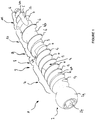
Figure 1 est une vue en perspective illustrant la vis osseuse à double filet discontinu suivant la présente invention. -
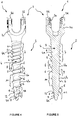
Figures 2 et 3 sont des vues de face et en coupe représentant la vis osseuse à double filet suivant la présente invention. -
Figures 4 et 5 sont des vues de face et en coupe montrant une variante de réalisation de la tête d'entraînement de vis osseuse à double filet discontinu suivant la présente invention. - On a montré en
figures 1 à 3 une vis osseuse 1 à double filet discontinu 5, 6 permettant d'assurer, par exemple, la fixation d'une prothèse ou d'un implant contre une partie osseuse. - La vis osseuse 1 comporte une tête d'entraînement 2 se prolongeant par un corps d'ancrage 3 constitué d'une âme cylindro-conique 4 sur laquelle s'étendent au moins deux filets cylindro-coniques discontinus 5, 6 assurant l'ancrage de ladite vis 1 dans les différentes composantes du tissu osseux.
- Dans cette première illustration, la tête d'entraînement 2 peut être constituée d'une tête à profil sphérique 2 a présentant dans sa partie interne une empreinte 2 b pour la mise en place d'un outil assurant l'entraînement en rotation de la vis osseuse 1.
Le corps d'ancrage 3 comprend sur toute sa longueur et à partir de la tête d'entraînement 2 des parties d'ancrage 7, 8, 9, 10 présentant respectivement des profils différents de manière à assurer un ancrage correspondant aux différentes duretés et résistances du tissu osseux - A cet effet, le corps d'ancrage 3 comporte en dessous de la tête d'entraînement 2 une première partie d'ancrage 7 qui est constituée de l'âme 4 dont le profil à ce niveau est conique 4 a et de deux filets 5, 6 à profil cylindriques et de pas identique.
Les deux filets 5, 6 à profil cylindrique sont décalés sur la périphérie de l'âme conique 4 a de 180° degrés. Dans cette première partie d'ancrage 7, la vis osseuse 1 présente un corps d'ancrage 3 à double filet permettant d'assurer une prise et un maintien de cette dernière dans l'os cortical du tissu osseux. - Le corps d'ancrage 3 comprend dans le prolongement de la première partie d'ancrage 7 une seconde partie d'ancrage 8 formée de l'âme 4 dont le profil dans cette zone est cylindrique 4 b et d'un seul filet cylindrique 5 positionné sur ¼ de tour dudit corps.
- Dans cette seconde partie d'ancrage 8 le second filet cylindrique 6 est arrêté pour ne laisser que le premier filet cylindrique 5 venir en contact avec le tissu osseux lors de la mise en place de la vis 1.
- Le corps d'ancrage 3 comporte dans le prolongement de la seconde partie d'ancrage 8 une troisième partie d'ancrage 9 pourvue de l'âme 4 dont le profil cylindrique 4 b est prolongé et de deux filets 5, 6 à profil cylindriques aménagés sur ½ tour dudit corps.
- Dans cette troisième partie d'ancrage 9 le second filet cylindrique 6 est repris suite à son arrêt dans la partie d'ancrage précédente, tandis que le premier filet cylindrique 5 est maintenu de manière continue depuis la première partie d'ancrage 7.
- Ainsi, la vis osseuse 1 présente au niveau de cette troisième partie d'ancrage 9 un corps d'ancrage 3 à double filet sur ½ tour afin d'augmenter son empreinte dans le tissu osseux.
- Le corps d'ancrage 3 comprend dans le prolongement de la troisième partie d'ancrage 9 une quatrième partie d'ancrage 10 formée de l'âme 4 dont le profil est cylindrique 4 b depuis la seconde partie d'ancrage 8 et d'un seul filet 6 à profil cylindrique qui s'étend sur n tour en fonction de la longueur totale de la vis osseuse 1.
- Dans cette quatrième partie d'ancrage 10 le premier filet cylindrique 5 est arrêté pour ne laisser que le second filet cylindrique 6 venir en contact avec le tissu osseux lors de la mise en place de la vis 1. On note que la quatrième partie d'ancrage 10 comprend un filet cylindrique 6 qui est différent du filet cylindrique 5 prévu pour la seconde partie 8.
- Le corps d'ancrage 3 comporte dans le prolongement de la quatrième partie d'ancrage 10 une cinquième et dernière partie d'ancrage 11 constituée de l'âme 4 dont le profil est à nouveau conique 4 a et des deux filets 5, 6 dont le profil est également conique afin de former avec le profil de l'âme 4 la pointe de la vis osseuse 1.
- Dans cette cinquième partie d'ancrage 11, la vis osseuse 1 présente un corps d'ancrage 3 à double filet permettant d'assurer la pénétration de cette dernière dans l'os cortical du tissu osseux.
- Egalement, la cinquième partie d'ancrage 11 de la vis osseuse 1 et plus particulièrement sa pointe comporte des empreintes 12 coupant verticalement le profil des deux filets 5 et 6.
Chaque empreinte 12 positionnée sur la périphérie de la pointe de la vis osseuse 1 permet de constituer sur les filets 5 et 6 des bords d'attaques tranchants 5 a et 6 a disposés dans le sens de rotation et d'introduction de ladite vis pour rendre lesdits filets auto-taraudants.
Selon une première variante la vis osseuse 1 à double filet discontinu 5, 6 peut comporter un alésage interne 13 permettant son guidage dans les tissus osseux au moyen d'un guide non représenté et préalablement introduit dans ledit tissus osseux.
Enfigures 4 et 5 , on a illustré une vis osseuse 1 comportant une tête d'entraînement 2 se prolongeant par un corps d'ancrage 3 constitué d'une âme cylindro-conique 4 sur laquelle s'étendent au moins deux filets cylindro-coniques discontinus 5, 6 assurant l'ancrage de ladite vis 1 dans les différentes composantes du tissu osseux. - Dans cette variante, la tête d'entraînement 2 est constituée d'une tête monobloc 2 c présentant un profil en forme de U solidaire du corps d'ancrage 3 présentant les parties d'ancrage 7, 8, 9, 10 de profils différents de manière à assurer un ancrage correspondant aux différentes duretés et résistance du tissu osseux.
- La tête monobloc 2 c présentant un profil en forme de U dont la partie interne des branches verticales 2 d comporte un filetage 2 e coopérant avec une vis serrage non représentée pour l'immobilisation, par exemple, d'une tige de liaison d'un dispositif d'ostéosynthèse rachidien.
- Il doit d'ailleurs être entendu que la description qui précède n'a été donnée qu'à titre d'exemple, et qu'elle ne limite nullement le domaine de l'invention qui est défini par les revendications.
Claims (7)
- Vis osseuse (1) à double filet discontinu pour la fixation d'une prothèse ou d'un implant contre une partie osseuse, comportant une tête d'entraînement d'entraînement (2) se prolongeant par un corps d'ancrage (3) constitué d'une âme cylindro-conique (4) sur laquelle s'étendent au moins deux filets cylindro-coniques (5, 6) assurant l'ancrage osseux de ladite vis (1), le corps d'ancrage (3) comprenant sur toute sa longueur et à partir de la tête d'entraînement (2) des parties d'ancrage de profil différents assurant un ancrage correspondant aux différentes duretés et résistances de l'os, caractérisé en ce que ledit corps d'ancrage (3) comporte en dessous de la tête d'entraînement (2) une première partie d'ancrage (7) constituée d'une âme conique (4 a ) et deux filets (5, 6) à profil cylindrique de pas identique, une seconde partie d'ancrage (8) formée d'une âme cylindrique (4 b ) et d'un seul filet cylindrique (5) sur ¼ de tour, une troisième partie d'ancrage (9) pourvue d'une âme cylindrique (4 b ) et de deux filets (5, 6) à profil cylindriques sur ½ tour, une quatrième partie d'ancrage (10) comprenant une âme cylindrique (4 b ) et un seul filet (6) à profil cylindrique sur n tour en fonction de la longueur totale de la vis osseuse (1), et une cinquième partie d'ancrage (11) comportant une âme conique (4 a ) et deux filets (5, 6) à profil conique formant la pointe de ladite vis osseuse.
- Vis osseuse à double filet discontinu suivant la revendication 1, caractérisée en ce que la première partie d'ancrage (7) comprend deux filets (5, 6) à profil cylindrique de pas identique décalés sur la périphérie de l'âme conique (4 a ) de 180° degré.
- Vis osseuse à double filet discontinu suivant la revendication 1, caractérisée en ce que la quatrième partie d'ancrage (10) comprend un filet cylindrique (6) qui est différent du filet cylindrique (5) prévu pour la seconde partie (8).
- Vis osseuse à double filet discontinu suivant la revendication 1, caractérisée en ce qu'elle comporte un alésage interne (13).
- Vis osseuse à double filet discontinu suivant la revendication 1, caractérisée en ce que la tête d'entraînement (2) est constituée d'une tête à profil sphérique (2 a ) présentant dans sa partie interne une empreinte (2 b ) pour la mise en place d'un outil.
- Vis osseuse à double filet discontinu suivant la revendication 1, caractérisée en ce que la tête d'entraînement (2) est constituée d'une tête monobloc (2 c ) présentant un profil en forme de U destiné à recevoir une vis serrage pour l'immobilisation d'un dispositif d'ostéosynthèse.
- Vis osseuse à double filet discontinu suivant la revendication 1, caractérisée en ce que la cinquième partie d'ancrage (11) à profil conique présente des filets (5, 6) auto taraudants.
Applications Claiming Priority (2)
| Application Number | Priority Date | Filing Date | Title |
|---|---|---|---|
| FR1560934A FR3043540B1 (fr) | 2015-11-16 | 2015-11-16 | Vis osseuse a double filet |
| PCT/FR2016/052896 WO2017085376A1 (fr) | 2015-11-16 | 2016-11-08 | Vis osseuse a double filet |
Publications (2)
| Publication Number | Publication Date |
|---|---|
| EP3376982A1 EP3376982A1 (fr) | 2018-09-26 |
| EP3376982B1 true EP3376982B1 (fr) | 2019-10-16 |
Family
ID=55073007
Family Applications (1)
| Application Number | Title | Priority Date | Filing Date |
|---|---|---|---|
| EP16806265.1A Active EP3376982B1 (fr) | 2015-11-16 | 2016-11-08 | Vis osseuse a double filet |
Country Status (11)
| Country | Link |
|---|---|
| EP (1) | EP3376982B1 (fr) |
| JP (1) | JP6847107B2 (fr) |
| AU (1) | AU2016355008B2 (fr) |
| BR (1) | BR112018009570A2 (fr) |
| CA (1) | CA3005328A1 (fr) |
| ES (1) | ES2759553T3 (fr) |
| FR (1) | FR3043540B1 (fr) |
| IL (1) | IL259209A (fr) |
| MX (1) | MX2018006002A (fr) |
| PT (1) | PT3376982T (fr) |
| WO (1) | WO2017085376A1 (fr) |
Families Citing this family (4)
| Publication number | Priority date | Publication date | Assignee | Title |
|---|---|---|---|---|
| AU2018347902A1 (en) | 2017-10-09 | 2020-02-27 | Conmed Corporation | Easy start cannulated bone screw |
| CN108066041B (zh) * | 2018-01-05 | 2024-04-16 | 北京博辉瑞进生物科技有限公司 | 可吸收钉及修补固定器 |
| US11000325B2 (en) * | 2018-02-27 | 2021-05-11 | Acumed Llc | Bone fastener with partially overlapping threads and a varying lead |
| CN110123433A (zh) * | 2019-05-15 | 2019-08-16 | 山东新华联合骨科器材股份有限公司 | 一种颈椎前路内固定系统 |
Family Cites Families (8)
| Publication number | Priority date | Publication date | Assignee | Title |
|---|---|---|---|---|
| US3861269A (en) | 1971-01-04 | 1975-01-21 | Superior Dry Wall Screw Mfg Co | Fastener with improved thread construction |
| US3703843A (en) | 1971-01-04 | 1972-11-28 | Msl Ind Inc | Fastener with improved thread construction |
| US20140121703A1 (en) * | 2012-10-31 | 2014-05-01 | Roger P. Jackson | Polyaxial bone anchor with pop-on multi-thread shank, some with diametric interference fit inserts |
| US8075604B2 (en) | 2006-02-16 | 2011-12-13 | Warsaw Orthopedic, Inc. | Multi-thread bone screw and method |
| US20140012334A1 (en) * | 2012-07-03 | 2014-01-09 | Warsaw Orthopedic, Inc. | Mutiple zone bone fastener |
| US9387027B2 (en) * | 2012-12-13 | 2016-07-12 | Jonathon Yigal Yahav | Implantable fixture |
| US9463057B2 (en) * | 2014-01-16 | 2016-10-11 | Amendia, Inc. | Orthopedic fastener |
| DE102014208012B3 (de) * | 2014-04-29 | 2015-08-27 | Silony Medical International AG | Osteosynthesevorrichtung |
-
2015
- 2015-11-16 FR FR1560934A patent/FR3043540B1/fr active Active
-
2016
- 2016-11-08 BR BR112018009570-2A patent/BR112018009570A2/pt not_active Application Discontinuation
- 2016-11-08 JP JP2018524319A patent/JP6847107B2/ja active Active
- 2016-11-08 ES ES16806265T patent/ES2759553T3/es active Active
- 2016-11-08 EP EP16806265.1A patent/EP3376982B1/fr active Active
- 2016-11-08 WO PCT/FR2016/052896 patent/WO2017085376A1/fr active Application Filing
- 2016-11-08 AU AU2016355008A patent/AU2016355008B2/en active Active
- 2016-11-08 PT PT168062651T patent/PT3376982T/pt unknown
- 2016-11-08 MX MX2018006002A patent/MX2018006002A/es unknown
- 2016-11-08 CA CA3005328A patent/CA3005328A1/fr not_active Abandoned
-
2018
- 2018-05-08 IL IL259209A patent/IL259209A/en unknown
Non-Patent Citations (1)
| Title |
|---|
| None * |
Also Published As
| Publication number | Publication date |
|---|---|
| JP6847107B2 (ja) | 2021-03-24 |
| ES2759553T3 (es) | 2020-05-11 |
| MX2018006002A (es) | 2018-09-17 |
| IL259209A (en) | 2018-07-31 |
| FR3043540A1 (fr) | 2017-05-19 |
| WO2017085376A1 (fr) | 2017-05-26 |
| PT3376982T (pt) | 2019-12-16 |
| AU2016355008A1 (en) | 2018-06-07 |
| JP2018535759A (ja) | 2018-12-06 |
| EP3376982A1 (fr) | 2018-09-26 |
| FR3043540B1 (fr) | 2017-12-29 |
| CA3005328A1 (fr) | 2017-05-26 |
| AU2016355008B2 (en) | 2021-03-11 |
| BR112018009570A2 (pt) | 2018-11-06 |
Similar Documents
| Publication | Publication Date | Title |
|---|---|---|
| EP3376982B1 (fr) | Vis osseuse a double filet | |
| EP2393441B1 (fr) | Vis d'osteosynthese et d'arthrodese | |
| EP0283373A1 (fr) | Vis vertébrale pour dispositif d'ostéosynthèse, notamment du rachis lombaire et dorsal | |
| CH671150A5 (fr) | ||
| WO2012131246A1 (fr) | Plaque d'ostéosynthèse | |
| EP3206607B1 (fr) | Clou centro-medullaire | |
| EP3310282B1 (fr) | Implant pour la fixation d'éléments osseux | |
| FR2971138A1 (fr) | Prothese d'osteosynthese destinee a la reduction des fractures non deplacees | |
| CA2711775A1 (fr) | Dispositif d'osteosynthese a moyens de fixation rapides | |
| WO2013175099A1 (fr) | Vis autocompressive d'osteosynthese | |
| EP2996590B1 (fr) | Ensemble de reprise pour un materiel d'osteosynthese vertebrale | |
| EP2863818B1 (fr) | Vis d'osteosynthese a compression radiale reduite | |
| EP4132391B1 (fr) | Implant d'ancrage osseux à stabilisation corticale | |
| CA3011033C (fr) | Dispositif d'implant | |
| EP2008599B1 (fr) | Système d'ostéosynthèse par plaque et vis osseuses | |
| EP1361827B1 (fr) | Vis de fixation | |
| EP2807985B1 (fr) | Plaque humérale | |
| EP2991567B1 (fr) | Perfectionnement aux fixateurs externes | |
| FR2913330A1 (fr) | Dispositif d'ancrage vertebral par clou intrapediculaire | |
| FR2880254A1 (fr) | Dispositif d'implant pour materiel d'osteosynthese vertebrale et outil pour sa mise en place | |
| FR2749157A1 (fr) | Clou implantable dans le canal medullaire d'un os long | |
| FR2828643A1 (fr) | Plaque d'osteosynthese notamment rachidienne | |
| FR2523838A1 (fr) | Tenon filete pour l'ancrage canalaire du materiau de reconstitution d'une dent | |
| FR2833152A1 (fr) | Dispositif d'ancrage osseux compressif |
Legal Events
| Date | Code | Title | Description |
|---|---|---|---|
| STAA | Information on the status of an ep patent application or granted ep patent |
Free format text: STATUS: UNKNOWN |
|
| STAA | Information on the status of an ep patent application or granted ep patent |
Free format text: STATUS: THE INTERNATIONAL PUBLICATION HAS BEEN MADE |
|
| PUAI | Public reference made under article 153(3) epc to a published international application that has entered the european phase |
Free format text: ORIGINAL CODE: 0009012 |
|
| STAA | Information on the status of an ep patent application or granted ep patent |
Free format text: STATUS: REQUEST FOR EXAMINATION WAS MADE |
|
| 17P | Request for examination filed |
Effective date: 20180430 |
|
| AK | Designated contracting states |
Kind code of ref document: A1 Designated state(s): AL AT BE BG CH CY CZ DE DK EE ES FI FR GB GR HR HU IE IS IT LI LT LU LV MC MK MT NL NO PL PT RO RS SE SI SK SM TR |
|
| AX | Request for extension of the european patent |
Extension state: BA ME |
|
| DAV | Request for validation of the european patent (deleted) | ||
| DAX | Request for extension of the european patent (deleted) | ||
| GRAP | Despatch of communication of intention to grant a patent |
Free format text: ORIGINAL CODE: EPIDOSNIGR1 |
|
| STAA | Information on the status of an ep patent application or granted ep patent |
Free format text: STATUS: GRANT OF PATENT IS INTENDED |
|
| INTG | Intention to grant announced |
Effective date: 20190508 |
|
| GRAS | Grant fee paid |
Free format text: ORIGINAL CODE: EPIDOSNIGR3 |
|
| GRAA | (expected) grant |
Free format text: ORIGINAL CODE: 0009210 |
|
| STAA | Information on the status of an ep patent application or granted ep patent |
Free format text: STATUS: THE PATENT HAS BEEN GRANTED |
|
| AK | Designated contracting states |
Kind code of ref document: B1 Designated state(s): AL AT BE BG CH CY CZ DE DK EE ES FI FR GB GR HR HU IE IS IT LI LT LU LV MC MK MT NL NO PL PT RO RS SE SI SK SM TR |
|
| REG | Reference to a national code |
Ref country code: GB Ref legal event code: FG4D Free format text: NOT ENGLISH |
|
| REG | Reference to a national code |
Ref country code: CH Ref legal event code: EP |
|
| REG | Reference to a national code |
Ref country code: DE Ref legal event code: R096 Ref document number: 602016022663 Country of ref document: DE |
|
| REG | Reference to a national code |
Ref country code: IE Ref legal event code: FG4D Free format text: LANGUAGE OF EP DOCUMENT: FRENCH |
|
| REG | Reference to a national code |
Ref country code: AT Ref legal event code: REF Ref document number: 1190532 Country of ref document: AT Kind code of ref document: T Effective date: 20191115 |
|
| REG | Reference to a national code |
Ref country code: PT Ref legal event code: SC4A Ref document number: 3376982 Country of ref document: PT Date of ref document: 20191216 Kind code of ref document: T Free format text: AVAILABILITY OF NATIONAL TRANSLATION Effective date: 20191204 |
|
| REG | Reference to a national code |
Ref country code: NL Ref legal event code: MP Effective date: 20191016 |
|
| REG | Reference to a national code |
Ref country code: LT Ref legal event code: MG4D |
|
| REG | Reference to a national code |
Ref country code: AT Ref legal event code: MK05 Ref document number: 1190532 Country of ref document: AT Kind code of ref document: T Effective date: 20191016 |
|
| PG25 | Lapsed in a contracting state [announced via postgrant information from national office to epo] |
Ref country code: FI Free format text: LAPSE BECAUSE OF FAILURE TO SUBMIT A TRANSLATION OF THE DESCRIPTION OR TO PAY THE FEE WITHIN THE PRESCRIBED TIME-LIMIT Effective date: 20191016 Ref country code: NO Free format text: LAPSE BECAUSE OF FAILURE TO SUBMIT A TRANSLATION OF THE DESCRIPTION OR TO PAY THE FEE WITHIN THE PRESCRIBED TIME-LIMIT Effective date: 20200116 Ref country code: GR Free format text: LAPSE BECAUSE OF FAILURE TO SUBMIT A TRANSLATION OF THE DESCRIPTION OR TO PAY THE FEE WITHIN THE PRESCRIBED TIME-LIMIT Effective date: 20200117 Ref country code: PL Free format text: LAPSE BECAUSE OF FAILURE TO SUBMIT A TRANSLATION OF THE DESCRIPTION OR TO PAY THE FEE WITHIN THE PRESCRIBED TIME-LIMIT Effective date: 20191016 Ref country code: LT Free format text: LAPSE BECAUSE OF FAILURE TO SUBMIT A TRANSLATION OF THE DESCRIPTION OR TO PAY THE FEE WITHIN THE PRESCRIBED TIME-LIMIT Effective date: 20191016 Ref country code: NL Free format text: LAPSE BECAUSE OF FAILURE TO SUBMIT A TRANSLATION OF THE DESCRIPTION OR TO PAY THE FEE WITHIN THE PRESCRIBED TIME-LIMIT Effective date: 20191016 Ref country code: LV Free format text: LAPSE BECAUSE OF FAILURE TO SUBMIT A TRANSLATION OF THE DESCRIPTION OR TO PAY THE FEE WITHIN THE PRESCRIBED TIME-LIMIT Effective date: 20191016 Ref country code: AT Free format text: LAPSE BECAUSE OF FAILURE TO SUBMIT A TRANSLATION OF THE DESCRIPTION OR TO PAY THE FEE WITHIN THE PRESCRIBED TIME-LIMIT Effective date: 20191016 Ref country code: SE Free format text: LAPSE BECAUSE OF FAILURE TO SUBMIT A TRANSLATION OF THE DESCRIPTION OR TO PAY THE FEE WITHIN THE PRESCRIBED TIME-LIMIT Effective date: 20191016 Ref country code: BG Free format text: LAPSE BECAUSE OF FAILURE TO SUBMIT A TRANSLATION OF THE DESCRIPTION OR TO PAY THE FEE WITHIN THE PRESCRIBED TIME-LIMIT Effective date: 20200116 |
|
| REG | Reference to a national code |
Ref country code: ES Ref legal event code: FG2A Ref document number: 2759553 Country of ref document: ES Kind code of ref document: T3 Effective date: 20200511 |
|
| PG25 | Lapsed in a contracting state [announced via postgrant information from national office to epo] |
Ref country code: IS Free format text: LAPSE BECAUSE OF FAILURE TO SUBMIT A TRANSLATION OF THE DESCRIPTION OR TO PAY THE FEE WITHIN THE PRESCRIBED TIME-LIMIT Effective date: 20200224 Ref country code: RS Free format text: LAPSE BECAUSE OF FAILURE TO SUBMIT A TRANSLATION OF THE DESCRIPTION OR TO PAY THE FEE WITHIN THE PRESCRIBED TIME-LIMIT Effective date: 20191016 Ref country code: HR Free format text: LAPSE BECAUSE OF FAILURE TO SUBMIT A TRANSLATION OF THE DESCRIPTION OR TO PAY THE FEE WITHIN THE PRESCRIBED TIME-LIMIT Effective date: 20191016 |
|
| PG25 | Lapsed in a contracting state [announced via postgrant information from national office to epo] |
Ref country code: AL Free format text: LAPSE BECAUSE OF FAILURE TO SUBMIT A TRANSLATION OF THE DESCRIPTION OR TO PAY THE FEE WITHIN THE PRESCRIBED TIME-LIMIT Effective date: 20191016 |
|
| REG | Reference to a national code |
Ref country code: CH Ref legal event code: PL |
|
| REG | Reference to a national code |
Ref country code: DE Ref legal event code: R097 Ref document number: 602016022663 Country of ref document: DE |
|
| PG2D | Information on lapse in contracting state deleted |
Ref country code: IS |
|
| PG25 | Lapsed in a contracting state [announced via postgrant information from national office to epo] |
Ref country code: CH Free format text: LAPSE BECAUSE OF NON-PAYMENT OF DUE FEES Effective date: 20191130 Ref country code: DK Free format text: LAPSE BECAUSE OF FAILURE TO SUBMIT A TRANSLATION OF THE DESCRIPTION OR TO PAY THE FEE WITHIN THE PRESCRIBED TIME-LIMIT Effective date: 20191016 Ref country code: MC Free format text: LAPSE BECAUSE OF FAILURE TO SUBMIT A TRANSLATION OF THE DESCRIPTION OR TO PAY THE FEE WITHIN THE PRESCRIBED TIME-LIMIT Effective date: 20191016 Ref country code: RO Free format text: LAPSE BECAUSE OF FAILURE TO SUBMIT A TRANSLATION OF THE DESCRIPTION OR TO PAY THE FEE WITHIN THE PRESCRIBED TIME-LIMIT Effective date: 20191016 Ref country code: CZ Free format text: LAPSE BECAUSE OF FAILURE TO SUBMIT A TRANSLATION OF THE DESCRIPTION OR TO PAY THE FEE WITHIN THE PRESCRIBED TIME-LIMIT Effective date: 20191016 Ref country code: LU Free format text: LAPSE BECAUSE OF NON-PAYMENT OF DUE FEES Effective date: 20191108 Ref country code: EE Free format text: LAPSE BECAUSE OF FAILURE TO SUBMIT A TRANSLATION OF THE DESCRIPTION OR TO PAY THE FEE WITHIN THE PRESCRIBED TIME-LIMIT Effective date: 20191016 Ref country code: LI Free format text: LAPSE BECAUSE OF NON-PAYMENT OF DUE FEES Effective date: 20191130 Ref country code: IS Free format text: LAPSE BECAUSE OF FAILURE TO SUBMIT A TRANSLATION OF THE DESCRIPTION OR TO PAY THE FEE WITHIN THE PRESCRIBED TIME-LIMIT Effective date: 20200216 |
|
| PLBE | No opposition filed within time limit |
Free format text: ORIGINAL CODE: 0009261 |
|
| STAA | Information on the status of an ep patent application or granted ep patent |
Free format text: STATUS: NO OPPOSITION FILED WITHIN TIME LIMIT |
|
| PG25 | Lapsed in a contracting state [announced via postgrant information from national office to epo] |
Ref country code: SK Free format text: LAPSE BECAUSE OF FAILURE TO SUBMIT A TRANSLATION OF THE DESCRIPTION OR TO PAY THE FEE WITHIN THE PRESCRIBED TIME-LIMIT Effective date: 20191016 Ref country code: IT Free format text: LAPSE BECAUSE OF FAILURE TO SUBMIT A TRANSLATION OF THE DESCRIPTION OR TO PAY THE FEE WITHIN THE PRESCRIBED TIME-LIMIT Effective date: 20191016 Ref country code: SM Free format text: LAPSE BECAUSE OF FAILURE TO SUBMIT A TRANSLATION OF THE DESCRIPTION OR TO PAY THE FEE WITHIN THE PRESCRIBED TIME-LIMIT Effective date: 20191016 |
|
| 26N | No opposition filed |
Effective date: 20200717 |
|
| PG25 | Lapsed in a contracting state [announced via postgrant information from national office to epo] |
Ref country code: IE Free format text: LAPSE BECAUSE OF NON-PAYMENT OF DUE FEES Effective date: 20191108 |
|
| PG25 | Lapsed in a contracting state [announced via postgrant information from national office to epo] |
Ref country code: SI Free format text: LAPSE BECAUSE OF FAILURE TO SUBMIT A TRANSLATION OF THE DESCRIPTION OR TO PAY THE FEE WITHIN THE PRESCRIBED TIME-LIMIT Effective date: 20191016 |
|
| PG25 | Lapsed in a contracting state [announced via postgrant information from national office to epo] |
Ref country code: CY Free format text: LAPSE BECAUSE OF FAILURE TO SUBMIT A TRANSLATION OF THE DESCRIPTION OR TO PAY THE FEE WITHIN THE PRESCRIBED TIME-LIMIT Effective date: 20191016 |
|
| PG25 | Lapsed in a contracting state [announced via postgrant information from national office to epo] |
Ref country code: HU Free format text: LAPSE BECAUSE OF FAILURE TO SUBMIT A TRANSLATION OF THE DESCRIPTION OR TO PAY THE FEE WITHIN THE PRESCRIBED TIME-LIMIT; INVALID AB INITIO Effective date: 20161108 Ref country code: MT Free format text: LAPSE BECAUSE OF FAILURE TO SUBMIT A TRANSLATION OF THE DESCRIPTION OR TO PAY THE FEE WITHIN THE PRESCRIBED TIME-LIMIT Effective date: 20191016 |
|
| PG25 | Lapsed in a contracting state [announced via postgrant information from national office to epo] |
Ref country code: TR Free format text: LAPSE BECAUSE OF FAILURE TO SUBMIT A TRANSLATION OF THE DESCRIPTION OR TO PAY THE FEE WITHIN THE PRESCRIBED TIME-LIMIT Effective date: 20191016 |
|
| PG25 | Lapsed in a contracting state [announced via postgrant information from national office to epo] |
Ref country code: MK Free format text: LAPSE BECAUSE OF FAILURE TO SUBMIT A TRANSLATION OF THE DESCRIPTION OR TO PAY THE FEE WITHIN THE PRESCRIBED TIME-LIMIT Effective date: 20191016 |
|
| P01 | Opt-out of the competence of the unified patent court (upc) registered |
Effective date: 20230606 |
|
| PGFP | Annual fee paid to national office [announced via postgrant information from national office to epo] |
Ref country code: GB Payment date: 20231127 Year of fee payment: 8 |
|
| PGFP | Annual fee paid to national office [announced via postgrant information from national office to epo] |
Ref country code: ES Payment date: 20231201 Year of fee payment: 8 |
|
| PGFP | Annual fee paid to national office [announced via postgrant information from national office to epo] |
Ref country code: PT Payment date: 20231020 Year of fee payment: 8 Ref country code: FR Payment date: 20231128 Year of fee payment: 8 Ref country code: DE Payment date: 20231129 Year of fee payment: 8 |
|
| PGFP | Annual fee paid to national office [announced via postgrant information from national office to epo] |
Ref country code: BE Payment date: 20231127 Year of fee payment: 8 |