EP3376945B1 - Systeme und verfahren zur nichtinvasiven messung von mechanischen materialeigenschaften und internen massenkräften und spannungen - Google Patents
Systeme und verfahren zur nichtinvasiven messung von mechanischen materialeigenschaften und internen massenkräften und spannungen Download PDFInfo
- Publication number
- EP3376945B1 EP3376945B1 EP16866811.9A EP16866811A EP3376945B1 EP 3376945 B1 EP3376945 B1 EP 3376945B1 EP 16866811 A EP16866811 A EP 16866811A EP 3376945 B1 EP3376945 B1 EP 3376945B1
- Authority
- EP
- European Patent Office
- Prior art keywords
- polymeric material
- oscillating
- force
- modulus
- strain
- Prior art date
- Legal status (The legal status is an assumption and is not a legal conclusion. Google has not performed a legal analysis and makes no representation as to the accuracy of the status listed.)
- Active
Links
Images




Classifications
-
- A—HUMAN NECESSITIES
- A61—MEDICAL OR VETERINARY SCIENCE; HYGIENE
- A61B—DIAGNOSIS; SURGERY; IDENTIFICATION
- A61B5/00—Measuring for diagnostic purposes; Identification of persons
- A61B5/0048—Detecting, measuring or recording by applying mechanical forces or stimuli
- A61B5/0051—Detecting, measuring or recording by applying mechanical forces or stimuli by applying vibrations
-
- G—PHYSICS
- G01—MEASURING; TESTING
- G01L—MEASURING FORCE, STRESS, TORQUE, WORK, MECHANICAL POWER, MECHANICAL EFFICIENCY, OR FLUID PRESSURE
- G01L1/00—Measuring force or stress, in general
- G01L1/10—Measuring force or stress, in general by measuring variations of frequency of stressed vibrating elements, e.g. of stressed strings
- G01L1/103—Measuring force or stress, in general by measuring variations of frequency of stressed vibrating elements, e.g. of stressed strings optical excitation or measuring of vibrations
-
- A—HUMAN NECESSITIES
- A61—MEDICAL OR VETERINARY SCIENCE; HYGIENE
- A61B—DIAGNOSIS; SURGERY; IDENTIFICATION
- A61B5/00—Measuring for diagnostic purposes; Identification of persons
-
- A—HUMAN NECESSITIES
- A61—MEDICAL OR VETERINARY SCIENCE; HYGIENE
- A61B—DIAGNOSIS; SURGERY; IDENTIFICATION
- A61B5/00—Measuring for diagnostic purposes; Identification of persons
- A61B5/0059—Measuring for diagnostic purposes; Identification of persons using light, e.g. diagnosis by transillumination, diascopy, fluorescence
- A61B5/0062—Arrangements for scanning
- A61B5/0066—Optical coherence imaging
-
- G—PHYSICS
- G01—MEASURING; TESTING
- G01L—MEASURING FORCE, STRESS, TORQUE, WORK, MECHANICAL POWER, MECHANICAL EFFICIENCY, OR FLUID PRESSURE
- G01L5/00—Apparatus for, or methods of, measuring force, work, mechanical power, or torque, specially adapted for specific purposes
- G01L5/04—Apparatus for, or methods of, measuring force, work, mechanical power, or torque, specially adapted for specific purposes for measuring tension in flexible members, e.g. ropes, cables, wires, threads, belts or bands
- G01L5/06—Apparatus for, or methods of, measuring force, work, mechanical power, or torque, specially adapted for specific purposes for measuring tension in flexible members, e.g. ropes, cables, wires, threads, belts or bands using mechanical means
-
- G—PHYSICS
- G01—MEASURING; TESTING
- G01N—INVESTIGATING OR ANALYSING MATERIALS BY DETERMINING THEIR CHEMICAL OR PHYSICAL PROPERTIES
- G01N3/00—Investigating strength properties of solid materials by application of mechanical stress
- G01N3/32—Investigating strength properties of solid materials by application of mechanical stress by applying repeated or pulsating forces
-
- G—PHYSICS
- G01—MEASURING; TESTING
- G01N—INVESTIGATING OR ANALYSING MATERIALS BY DETERMINING THEIR CHEMICAL OR PHYSICAL PROPERTIES
- G01N2203/00—Investigating strength properties of solid materials by application of mechanical stress
- G01N2203/0058—Kind of property studied
- G01N2203/0069—Fatigue, creep, strain-stress relations or elastic constants
- G01N2203/0075—Strain-stress relations or elastic constants
-
- G—PHYSICS
- G01—MEASURING; TESTING
- G01N—INVESTIGATING OR ANALYSING MATERIALS BY DETERMINING THEIR CHEMICAL OR PHYSICAL PROPERTIES
- G01N2203/00—Investigating strength properties of solid materials by application of mechanical stress
- G01N2203/0058—Kind of property studied
- G01N2203/0089—Biorheological properties
-
- G—PHYSICS
- G01—MEASURING; TESTING
- G01N—INVESTIGATING OR ANALYSING MATERIALS BY DETERMINING THEIR CHEMICAL OR PHYSICAL PROPERTIES
- G01N2203/00—Investigating strength properties of solid materials by application of mechanical stress
- G01N2203/0058—Kind of property studied
- G01N2203/0092—Visco-elasticity, solidification, curing, cross-linking degree, vulcanisation or strength properties of semi-solid materials
- G01N2203/0094—Visco-elasticity
-
- G—PHYSICS
- G01—MEASURING; TESTING
- G01N—INVESTIGATING OR ANALYSING MATERIALS BY DETERMINING THEIR CHEMICAL OR PHYSICAL PROPERTIES
- G01N2203/00—Investigating strength properties of solid materials by application of mechanical stress
- G01N2203/02—Details not specific for a particular testing method
- G01N2203/026—Specifications of the specimen
- G01N2203/0262—Shape of the specimen
- G01N2203/0278—Thin specimens
-
- G—PHYSICS
- G01—MEASURING; TESTING
- G01N—INVESTIGATING OR ANALYSING MATERIALS BY DETERMINING THEIR CHEMICAL OR PHYSICAL PROPERTIES
- G01N2203/00—Investigating strength properties of solid materials by application of mechanical stress
- G01N2203/02—Details not specific for a particular testing method
- G01N2203/06—Indicating or recording means; Sensing means
- G01N2203/0641—Indicating or recording means; Sensing means using optical, X-ray, ultraviolet, infrared or similar detectors
- G01N2203/0647—Image analysis
Definitions
- This document relates generally to non-invasive techniques for measuring material mechanical properties and internal body forces and stresses.
- mechanochemical transduction As body mass increases during development, the body adapts to external mechanical loading by increasing the size of the functional units through a process termed mechanochemical transduction.
- tissues found in mammals such as the eye, blood vessels, lungs and skin
- a dynamic loading pattern that stimulates mechanochemical transduction through the phosphorelay pathways is set up by tension at the tissue-cellular interface.
- the phosphorelay pathways control cell replication and protein synthesis in mammals.
- changes in the mechanical properties of tissues accompany the onset and progression of several diseases (e.g., atherosclerosis, cirrhosis, glaucoma, and cancer).
- ECMs Extra-Cellular Matrices
- Non-patent literature entitled " Vibrational Analysis Of Tendon, Mechanical Properties” written by Revel et al. (“Revel”) describes the use of a small hammer and a laser vibrometer to measure the vibrational velocity of an Achilles tendon during uniaxial tensile testing.
- This document reports a first resonant frequency of 47 to about 57 Hz for stress levels up to about 7 MPa.
- the first resonant frequency is a valued parameter for measurement of some physiological characteristics of tendon.
- the resonant frequencies appear to be very low for tendon considering the modulus of Achilles tendon is expected to be high.
- U.S. Patent No. 7,753,847 to Greenleaf et al. (“the '847 patent”) describes a method for measuring mechanical properties of a subject. Such measurement is achieved by: applying ultrasonic vibration pulses in an on-off time sequence; measuring characteristics of detected harmonic signals; and calculating the mechanical properties using the measured characteristics.
- This document reports an elasticity of 20 kPa for cirrhosis of the liver. This 20 kPa value is only a fraction of that reported for collagenous tissues and seems rather low.
- U.S. Patent No. 8,167,804 to Kim et al. discloses a method for monitoring vascular wall compliance by measuring the pulse wave velocity, the intramural strain and pulse wave velocity. This technique uses an assumed Poisson's ratio of 0.5 to calculate mechanical parameters. The use of an assumed Poisson's ratio is a problem in this approach.
- U.S. Patent No. 8,323,199 to Salcudean et al. discloses an apparatus for imaging mechanical properties of a tissue region from within an endocavity. Images are collected after a probe is inserted in a cavity and the probe is vibrated using ultrasound. It is unclear in the ⁇ 199 patent how the images are translated into mechanical properties using this method.
- U.S. Patent Publication No. 2014/0081138 to Bercoff et al. discloses a method for measuring a mean viscoelastic value of a soft material using a single probe with at least one transducer.
- the mean value is estimated by: inducing a constraint zone; measuring a displacement of the zone and of a zone away from the constraint zone; and determining a mean viscoelasticity of tissue displacement between the zones. It is unclear how the viscoelastic parameters measured using this approach compare with values reported in the literature
- OCE Optical Coherence Elastography
- U.S. Patent No. 9,043,156 to Gallippi et al. (“the ⁇ 156 patent”) describes a method for determining the mechanical property parameter of a sample by applying acoustic energy.
- the resulting mechanical property parameter requires the measurement of a response to acoustic energy application and the recovery response, as well as a determination of an additional mechanical parameter based on mathematical relationship between three (3) mechanical parameters.
- the limitation of this method is that it requires three (3) separate measurements and the result is an estimated elastic modulus.
- Hermawan Vera "Experimental Techniques to Determine the Young's Modulus of the Trachea", Masters Thesis, 30 September 2004 , explores multiple non-destructive testing techniques used to determine the Young modulus of elasticity of the trachea. The various techniques are benchmarked against what is referred to as a standard uniaxial state of stress method. It is explained that this method puts the tissue under extreme conditions and is a destructive approach.
- the present disclosure concerns systems and methods for non-invasive and non-destructive determinations of mechanical properties of a material.
- the material includes, but is not limited to, a material used in a commercial process, a material used in a laboratory process, a tissue in a living animal, or a tissue removed from a living animal.
- the methods comprise:
- the oscillating force is applied to the material by an electrical, magnetic, mechanical, electromechanical or vibrating element.
- This element is also referred to herein as an oscillating force generator.
- the oscillating force generator can be selected from the group consisting of a vibrating hammer, an oscillating hydraulic device, an oscillating acoustic device, an oscillating magnetic field generator, an oscillating electrical field generator, an oscillating electromagnetic field generator, and an oscillating piezoelectric crystal.
- the oscillating force can comprise an oscillating acoustic force.
- a tension of the material can range from zero Newton (0 N) to five hundred Newton (500 N) when the oscillating force is being applied thereto.
- E represents a modulus
- f n is the natural vibration frequency
- m represents a mass of the sample material
- L represents a length of the sample material
- A represents the cross-sectional area of the sample material.
- the elastic modulus is obtained by multiplying the modulus E by an elastic fraction measured separately on the material from incremental stress-strain curves.
- a viscoelasticity of the material may additionally or alternatively be measured when the oscillating force is being applied to the material.
- a first diagnosis is transformed into a more precise second diagnosis based on the elastic modulus and/or the viscoelasticity.
- tissue mechanical properties e.g., elastic modulus or stiffness
- pathogenesis of many diseases including fibrosis and cancer.
- diseases including fibrosis and cancer.
- tumors are much harder than healthy tissues.
- This change in the stiffness is routinely examined by physicians through palpation.
- Sensitive techniques and methods that can be used to noninvasively determine the mechanical property of tissue in patients, can lead to early diagnosis and treatment.
- the present disclosure concerns systems and methods for non-invasive and non-destructive determinations of mechanical properties in living patients.
- the mechanical properties include, but are not limited to, strain, elastic modulus and/or viscoelasticity.
- the determination is made by measuring the natural frequency of a tissue or material under tension.
- the non-invasive measurement improves the ability of clinicians to provide early diagnosis of highly prevalent conditions (e.g., cancer, fibrosis or other conditions associated with tissue stiffness).
- the present technique for non-invasive measurement of mechanical forces in tissues yields values found using destructive techniques.
- the mechanical forces acting on a tissue are measured by determining the strain on the tissue and modulus of the material using vibrational analysis.
- the modulus of a tissue is measured using vibrational analysis on a tissue and/or
- the viscoelasticity of a tissue is measured by determining the in-phase (elastic) and out-of-phase (viscous) response when an external vibration is applied.
- An oscillating mechanical load applied to tissue or other materials can be used to estimate the mechanical properties of these materials.
- the limitations of this oscillation based technique include the assumptions that material is linearly elastic, the material is incompressible, and the mechanical property (such as modulus) can be calculated from the displacement measurements made within the tissue.
- the assumption of linear elasticity and incompressibility are well known to have severe limitations since Poisson's ratios for tissue have been shown to vary significantly from a half (0.5).
- tissues are viscoelastic, and therefore the properties are time-dependent. The easiest way to separate out the elastic and viscous components in the viscoelastic response is to make measurements at zero (0) time and after relaxation has occurred.
- the calculated value of mechanical properties (such as the modulus) have significant errors introduced.
- the present disclosure concerns systems and methods in which an oscillating mechanical vibration is applied to a tissue and the natural frequency of the resulting vibrations that occurs as a result of the externally applied load is measured.
- the relationship between the natural frequency and vibrational modulus is given by Mathematical Equation (1).
- E 2 ⁇ n m 2 L A
- f n is the natural vibration frequency
- m represents a mass of the sample material
- L represents a length of the sample material
- A represents the cross-sectional area of the sample material.
- Mathematical Equation (1) states that the elastic modulus for a linear elastic material is related to the natural frequency squared of the resulting vibrations multiplied by the mass squared times the length divided by the cross-sectional area.
- the modulus can be obtained using Mathematical Equation (1).
- collagen and ECMs are viscoelastic, they behave quasi-elastically at high strains, i.e., the stress and strain appear linear.
- the elastic part of the modulus can be obtained by measuring the stress at equilibrium and correcting the modulus by the elastic fraction, i.e., the fraction of energy stored elastically.
- the elastic modulus can be obtained from Mathematical Equation (1).
- the modulus of a viscoelastic tissue can be obtained from Mathematical Equation (1) from the natural frequency by applying an external oscillation to an ECM that has been stretched into the linear region of the stress-strain curve.
- the elastic stress for collagen is approximately linear with strain and is strain-rate independent for strain-rates up to one thousand percent per second (1000%/sec). The viscous contribution to the stress is known to increase with strain-rate for collagen. This pertains to ECMs rich in the fibrillar collagens.
- the elastic modulus can be calculated from the modulus obtained from Mathematical Equation (1) after correction by the elastic fraction.
- the viscous contribution to the modulus can also be obtained from the difference between the total modulus calculated from the Mathematical Equation (1) times one (1) minus the elastic fraction.
- the decay time for a viscoelastic material is obtained from the time it takes the applied oscillating stress to decay to an equilibrium value. In this manner, the viscoelastic properties of a material can be obtained from the resonant frequency of a material that is oscillated using sinusoidal forces as described above.
- the force is applied to the material by a vibrating hammer, an oscillating hydraulic device, an oscillating acoustic device, an oscillating magnetic field generator, an oscillating electrical field generator, an oscillating electromagnetic field generator, an oscillating piezoelectric crystal, and/or any other electrical, magnetic and/or mechanical mechanisms that applies a varying force over time.
- a vibrating hammer an oscillating hydraulic device, an oscillating acoustic device, an oscillating magnetic field generator, an oscillating electrical field generator, an oscillating electromagnetic field generator, an oscillating piezoelectric crystal, and/or any other electrical, magnetic and/or mechanical mechanisms that applies a varying force over time.
- Each of the listed electrical, magnetic and/or mechanical mechanisms for applying forces to the material are well known in the art, and therefore will not be described herein. Any known or to be known electrical, magnetic and/or mechanical mechanism can be used herein without limitation.
- an oscillating acoustic force is applied to a material or wet tissue that is stretched so that the tension ranges from zero Newton (0 N) to five hundred Newton (500 N).
- the sample is allowed to oscillate through a series of cycles of loading and unloading at frequencies between ten Hertz (10 Hz) and two thousand Hertz (2000 Hz). Then, the oscillating acoustic force is removed from the sample.
- the sample is stretched to remove any undulations in it as well as to load the fibers or polymeric units that support the sample.
- the strain or stress as a function of time is measured and the natural frequency is determined by obtaining the Fourier transform of the strain or stress in the frequency domain.
- the elastic modulus is obtained by substitution into Mathematical Equation (1) presented above.
- the elastic modulus is obtained by multiplying the modulus obtained in Mathematical Equation (1) by the elastic fraction measured separately on the tissue from incremental stress-strain curves.
- the elastic fraction calibration curve is strain-rate dependent and is obtained from incremental stress-strain measurements on samples at different strain-rates.
- the elastic fraction is obtained by measuring the ratio of the instantaneous force or stress and dividing it by the equilibrium force or stress that occurs after the material has relaxed.
- FIG. 12 provides an incremental stress-strain curve for normal human articular cartilage.
- the initial stress represents a combination of the elastic and viscous components.
- the stress then decays to an equilibrium value (lower point at a constant strain).
- the equilibrium value represents the elastic stress while the initial stress (top point at a constant) represents a combination of the elastic and viscous stress.
- Elastic and viscous stress-strain curves for "normal" articular cartilage are constructed by connecting all the top and bottom points. An exemplary stress-strain curve is shown in FIG. 12 .
- the elastic component is independent of strain rate for fibrous ECMs.
- the elastic fraction is the ratio of the equilibrium stress to the initial stress.
- the elastic fraction of tendon is about seven tenths (0.7) while that of skin is five tenths (0.5) at strains of about five percent (5%) and the elastic fraction increased to seven tenths (0.7) at strains of about twenty percent (20%) or more.
- the modulus of materials was measured using tensile testing.
- Samples to be tested were prepared from strips of polymeric materials with dimensions two and a half centimeters (2.5 cm) wide, one millimeter (1 mm) thick and six and three tenths of a centimeter (6.3 cm) long weighing between one tenth of a gram (0.1 g) and one gram (1.0 g).
- the samples were placed in the grips of a micrometer connected to a force gauge and stretched until they were under a force of about half Newton (0.5 N).
- the samples were then stretched in strain increments of five hundredth of a percent (0.05%) and the force recorded.
- the stress strain curves were calculated from this data and a modulus was obtained from the slope of the stress-strain curve.
- the modulus was measured using vibrational analysis.
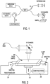
- the natural frequency was measured using an OCT system as shown in FIGS. 1-2 .
- FIG. 3 shows the square of the natural frequency plotted versus the modulus measured using tensile testing as described in EXAMPLE 1.
- the vibrational stage of the OCT included a micrometer by which the sample was stretched to the same extent as was done in the uniaxial tensile tests.
- a speaker was mounted under the sample and vibrated the sample to acoustic frequencies between one hundred Hertz (100 Hz) and one thousand Hertz (1000 Hz).
- the natural frequency of the sample was obtained from the driving frequency that produced the largest displacement in the sample's resonant frequency.
- the value of the elastic modulus was calculated from Mathematical Equation (1).
- the tensile and vibrational moduli for silicone rubber model materials were measured.
- the tensile E and vibrational Ev moduli of silicone elastomers were measured using the methods of EXAMPLES 1 and 2 described above.
- the silicone elastomeric base was mixed with curing agent at a 10:1 ratio and allowed to cure at twenty-five degrees Celsius (25 °C) overnight.
- a value of the resonant frequency of three hundred sixty (360) cycles per second was obtained for a sample that after use of Mathematical Equation (1) resulted in a value of Ev ninety-one hundredths of a Mega-Pascal (0.91 MPa).
- the value of E from the slope of the tensile measurements was found to be eight tenths of a Mega-Pascal (0.80 MPa).
- the tensile and vibrational moduli for a rubber glove were measured. Samples of rubber obtained from a rubber glove were prepared and tested according to EXAMPLES 1 and 2. The value of the resonant frequency for the rubber glove was found to be one hundred twenty-seven (127) cycles per second. This translated into a value of Ev of sixtyfour hundredths of a Mega-Pascal (0.64 MPa) using Mathematical Equation (1). The value of the tensile modulus was found to be eighth tenths (0.80) using uniaxial tensile tests.
- the tensile and vibrational moduli for decellurized dermis were measured. Samples of decelluralized dermis were obtained. The samples were stretched with the micrometer stage to about ten percent (10%) and tested to determine the moduli as described in EXAMPLES 1 and 2. The natural frequency obtained was six hundred sixty-three (663) cycles per second. This was equivalent to a modulus of four and ninety-three hundredths of a Mega-Pascal (4.93 MPa). The modulus obtained from uniaxial tensile tests was four Mega-Pascal (4.0 MPa).
- a material e.g., an elastic and/or viscoelastic material.
- the material includes, but is not limited to, a material used in a commercial process/product (e.g., an airplane part), a material used in a laboratory process, a tissue in a living animal, or a tissue removed from a living animal.
- Method 400 begins with step 402 and continues with step 404 where a material or wet tissue (e.g., tissue sample 208 of FIG. 2 ) is stretched (e.g., so that the tension ranges between 0 N to 500 N) at one or more ends thereof.
- a material or wet tissue e.g., tissue sample 208 of FIG. 2
- clamps e.g., clamps 202 of FIG. 1
- the clamps are moved in opposing directions (e.g., directions 204 and 206 of FIG. 1 ) which causes the tissue to be made longer without tearing or breaking. Movement of the clamps causes a pulling force to be applied to the material or wet tissue.
- Clamps are well known in the art, and therefore will not be described herein. Any known or to be known clamps can be used herein without limitation. Also, other mechanical securement mechanisms can be employed in addition to or as alternatives to the clamps. As should be understood, operations of the clamps and other mechanical securement mechanisms can be controlled by a controller, such as a computing system and/or driving mechanical device (e.g., a motor). Controllers, computing systems and mechanical devices are well known in the art, and therefore will not be described in detail herein. An exemplary computing system is discussed below in relation to FIG. 5 .
- an oscillating mechanical vibration or an oscillating acoustic force is applied to the stretched material or tissue.
- a force transducer e.g., force transducer 210 of FIG. 2
- the force transducer can be arranged to move in two opposing directions (e.g., directions 212 of FIG. 2 ) which are both perpendicular to the directions (e.g., directions 204-206 of FIG. 2 ) in which the clamps are moved for purposes of stretching the tissue.
- operations of the force transducer can be controlled by a controller, such as a computing system.
- the oscillating force is applied to the stretched material/tissue by an electrical, magnetic, mechanical, electromechanical or vibrating element.
- the electrical, magnetic, mechanical, electromechanical or vibrating element can include, but is not limited to, a vibrating hammer, an oscillating hydraulic device, an oscillating acoustic device, an oscillating magnetic field generator, an oscillating electrical field generator, an oscillating electromagnetic field generator, and/or an oscillating piezoelectric crystal.
- step 408 the material or tissue is further stretched to remove any undulations in it as well as to load the fibers or polymeric units that support the same.
- the material or tissue is then allowed to oscillate through a series of cycles of loading and unloading (e.g., between frequencies of 10 Hz to 2000 Hz), as shown by step 410 .
- the strain and stress on the material or tissue is then measured as a function of time, as shown by step 412 .
- the natural frequencies of the material and subcomponents are determined in step 414 . This determination is achieved by obtaining the Fourier Transform of the strain and stress in the frequency domain.
- the strain provides a measurement for the vibrational modulus.
- the stress provides a measurement for the tensile modulus.
- a vibrational OTC measurement can be made to obtain the vibrational modulus.
- FIG. 6 An exemplary calibration curve of vibrational modulus from Mathematical Equation (1) versus tensile modulus is shown in FIG. 6 for silicone rubber and decellularized dermis, where the tensile modulus was calculated from uniaxial incremental stress-strain curves.
- An exemplary tensile stress-strain curve for decellularized dermis is shown in FIG. 7 .
- An exemplary graph showing the natural frequency for a material composed of a single component (e.g., decellularized dermis) at a strain of five percent (5%) is provided in FIG. 8 .
- FIG. 9 An exemplary graph is provided in FIG. 9 that shows the dependence of the natural frequency of the material on the strain.
- TABLE 1 comprises a calibration table of natural frequency and tissue components.
- TABLE 1 Tissue Component Strain Natural Frequency Dermis Collagen Fibers 5% 150 14% 260 20% 350 Cartilage Collagen Fibers 3% About 150 Bone 3% 900
- FIGS. 10-11 A typical determination of the natural frequencies of a multicomponent material (e.g., Bovine Articular Cartilage) is shown in FIGS. 10-11 .
- a multicomponent material e.g., Bovine Articular Cartilage
- the OTC measurement can be made via a handheld scanner.
- the handheld scanner implements all or a portion of method 400 .
- the handheld scanner may include components for applying oscillating forces to the secured material and/or a computing device for determining a material's stress, strain, natural frequency, elastic modulus and/or viscoelasticity.
- An exemplary architecture for a computing device which can be contained in the handheld device is provided in FIG. 5 .
- the present solution is not limited in this regard.
- the tissue does not need to be stretched at either end since most tissues are under tension.
- the vibrational modulus can be determined using other techniques than the OTC based technique described herein. These other techniques include, but are not limited to, ultrasound, Magnetic Resonance Imaging ("MRI"), light microscopy, photography, and/or infrared photograph. In this case, the principle is the same: the modulus of a material can be determined by measuring the frequency that results in the maximum displacement of the material being vibrated. For instance, ultrasound works in the Mega-Hertz range. In method 400 , the material is vibrated at a frequency between zero Hertz (0 Hz) and one thousand five hundred Hertz (1500 Hz).
- MRI Magnetic Resonance Imaging
- the change in the material's dimension (or material's displacement) created by the low frequency vibration is measured via ultrasound imaging.
- the present solution is not limited to the particulars of this ultrasound example.
- the elastic modulus of the material and subcomponents are optionally determined in step 416 using the natural frequency.
- the elastic modulus is determined using Mathematical Equation (1) presented above.
- a modulus E is obtained by solving Mathematical Equation (1).
- the elastic modulus is obtained by multiplying the modulus E by an elastic fraction measured separately on the material from incremental stress-strain curves.
- the present solution is not limited to the techniques discussed herein for determining the elastic modulus. Other techniques can be used here without limitation.
- the viscoelasticity of the material and subcomponents may optionally be measured as well as shown by step 418 .
- the viscoelasticity is measured by determining in-phase (elastic) or out-of-phase (viscous) response when an external vibration is applied to the material.
- the viscous contribution to the elastic modulus is obtained from the difference between the total elastic modulus times one (1) minus the elastic fraction.
- the decay time for the material is obtained from the time it takes the applied oscillating stress to decay to an equilibrium value.
- the natural frequency, elastic modulus and/or viscoelasticity of the material and/or subcomponents is(are) then used in step 420 to optionally generate an improved diagnosis or validate a previous diagnosis of a subject's condition (e.g., cancer, fibrosis or other conditions associated with tissue stiffness).
- a diagnosis is improved here because the present technique provides a means to directly compute an elastic modulus (whereas in other conventional techniques a tangent to a curve needs to be derived which provides less accurate results especially for viscoelastic materials).
- the improved diagnosis can involve translating or transforming a first diagnosis into a more precise second diagnosis. For example, the first diagnosis is the existence of a tumor, and the more precise second diagnosis is a tumor that was malignant.
- the diagnosis is generated by the computing system using prestored Look Up Tables ("LUTs") of information correlating medical conditions with natural frequency, elastic modulus, and/or viscoelasticity values.
- LUTs Look Up Tables
- An exemplary LUT is provided below as TABLE 2.
- TABLE 2 Condition Change in Modulus With Respect to Values for Normal Tissues Arteriosclerosis Decreased Cancerous Tumor Increased Fatty Liver Decreased Left Ventricular Hypertrophy Decreased Liver Fibrosis Increased Osteoarthritis Decreased Pulmonary Fibrosis Increased Scar Tissue Increased
- various algorithms can be employed to compute a diagnosis value using the values determined for natural frequency, elastic modulus and/or viscoelasticity.
- an amplitude of the signal can be used as a weighting factor for diagnosis purposes.
- the tissue behavior can be modeled by multiply the amplitude of the signal by the frequency, and calculating the overall tissue modulus. Let's assume that collagen of a first type vibrates at natural frequency X 1 and has an associated signal amplitude of A 1 . Collagen of a second type vibrates at natural frequency X 2 and has an associated signal amplitude of A 2 .
- T behavior is then used to generate a diagnosis value for a given subject.
- the present solution is not limited to the particulars of this example.
- step 422 unwanted cells or tissue in tumors are selectively removed by applying a high energy signal at the natural frequency of the components to be removed. For example, it is desirable to only remove cells from the material and not collagen. The cells have a natural frequency much lower than the collagen. Therefore, if the material is vibrated at the lower natural frequency, then the cells would be removed and not the collagen. The present solution is not limited in this regard.
- step 424 is performed where method 400 ends or other processing is performed.
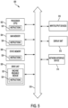
- FIG. 5 there is shown a hardware block diagram comprising an exemplary computer system 500 .
- the machine can include a set of instructions which are used to cause the computer system to perform any one or more of the methodologies discussed herein.
- the machine can function as a server or a router.
- the exemplary computer system 500 can correspond to the computing system 200 of FIG. 2 .
- the computer system 500 can operate independently as a standalone device. However, the present solution is not limited in this regard and in other scenarios the computer system can be operatively connected (networked) to other machines in a distributed environment to facilitate certain operations described herein. Accordingly, while only a single machine is illustrated in FIG. 5 , it should be understood that the present solution can be taken to involve any collection of machines that individually or jointly execute one or more sets of instructions as described herein.
- the computer system 500 is comprised of a processor 502 (e.g., a Central Processing Unit (“CPU”)), a main memory 504 , a static memory 506 , a drive unit 508 for mass data storage and comprised of machine readable media 520 , input/output devices 510 , a display unit 512 (e.g., a Liquid Crystal Display (“LCD”), a solid state display, or a Cathode Ray Tube (“CRT”)), and a network interface device 514 . Communications among these various components can be facilitated by means of a data bus 518 .
- One or more sets of instructions 524 can be stored completely or partially in one or more of the main memory 504 , static memory 506 , and drive unit 508 .
- the instructions can also reside within the processor 502 during execution thereof by the computer system.
- the input/output devices 510 can include a keyboard, a keypad, a mouse, buttons, a multi-touch surface (e.g., a touchscreen), a speaker, a microphone, an imaging capturing device, and so on.
- the network interface device 514 can be comprised of hardware components and software or firmware to facilitate wired or wireless network data communications in accordance with a network communication protocol utilized by a data network (e.g., a Local Area Network ("LAN”) and/or a Wide Area Network (“WAN”)).
- LAN Local Area Network
- WAN Wide Area Network
- the drive unit 508 can comprise a machine readable medium 520 on which is stored one or more sets of instructions 524 (e.g., software) which are used to facilitate one or more of the methodologies and functions described herein.
- the term "machine-readable medium” shall be understood to include any tangible medium that is capable of storing instructions or data structures which facilitate any one or more of the methodologies of the present disclosure.
- Exemplary machine-readable media can include magnetic media, solid-state memories, opticalmedia and so on. More particularly, tangible media as described herein can include; magnetic disks; magneto-optical disks; CD-ROM disks and DVD-ROM disks, semiconductor memory devices, Electrically Erasable Programmable Read-Only Memory (“EEPROM”)) and flash memory devices.
- EEPROM Electrically Erasable Programmable Read-Only Memory
- a tangible medium as described herein is one that is non-transitory insofar as it does not involve a propagating signal.
- Computer system 500 should be understood to be one possible example of a computer system which can be used in connection with the various implementations. However, the present solution is not limited in this regard and any other suitable computer system architecture can also be used without limitation.
- Dedicated hardware implementations including, but not limited to, application-specific integrated circuits, programmable logic arrays, and other hardware devices can likewise be constructed to implement the methods described herein.
- Applications that can include the apparatus and systems of various implementations broadly include a variety of electronic and computer systems. Some implementations may implement functions in two or more specific interconnected hardware modules or devices with related control and data signals communicated between and through the modules, or as portions of an application-specific integrated circuit.
- the exemplary system is applicable to software, firmware, and hardware implementations.
- the present solution can take the form of a computer program product on a tangible computer-usable storage medium (for example, a hard disk or a CD-ROM).
- the computer-usable storage medium can have computer-usable program code embodied in the medium.
- the term computer program product, as used herein, refers to a device comprised of all the features enabling the implementation of the methods described herein.
- Computer program, software application, computer software routine, and/or other variants of these terms mean any expression, in any language, code, or notation, of a set of instructions intended to cause a system having an information processing capability to perform a particular function either directly or after either or both of the following: a) conversion to another language, code, or notation; or b) reproduction in a different material form.
Landscapes
- Health & Medical Sciences (AREA)
- Life Sciences & Earth Sciences (AREA)
- Physics & Mathematics (AREA)
- Pathology (AREA)
- General Health & Medical Sciences (AREA)
- Medical Informatics (AREA)
- Veterinary Medicine (AREA)
- Engineering & Computer Science (AREA)
- Biomedical Technology (AREA)
- Heart & Thoracic Surgery (AREA)
- Molecular Biology (AREA)
- Surgery (AREA)
- Animal Behavior & Ethology (AREA)
- Biophysics (AREA)
- Public Health (AREA)
- General Physics & Mathematics (AREA)
- Nuclear Medicine, Radiotherapy & Molecular Imaging (AREA)
- Radiology & Medical Imaging (AREA)
- Chemical & Material Sciences (AREA)
- Analytical Chemistry (AREA)
- Biochemistry (AREA)
- Immunology (AREA)
- Ultra Sonic Daignosis Equipment (AREA)
Claims (20)
- Verfahren (400) für nicht invasive und nicht zerstörende Bestimmungen mechanischer Eigenschaften eines Polymermaterials (208), umfassend:Koppeln eines ersten Endes des Polymermaterials (208) mit einem ersten mechanischen Mechanismus (202), der in einer ersten Richtung (204) bewegbar ist, und Koppeln eines zweiten Endes des Polymermaterials (208) mit einem zweiten mechanischen Mechanismus (202), der in einer zweiten Richtung (206), der ersten Richtung (204) entgegengesetzt, bewegbar ist;Ausüben einer Zugkraft, um das Polymermaterial (208) durch Bewegen des ersten und des zweiten mechanischen Mechanismus (202) um einen ersten Abstand in eine jeweilige erste und zweite Richtung (204, 206) zu dehnen;Ausüben einer oszillierenden Kraft auf das Polymermaterial (208), auf das die Zugkraft ausgeübt wird;Entfernen der oszillierenden Kraft von dem Polymermaterial (208);weiteres Dehnen des Polymermaterials (208) durch Bewegen des ersten und des zweiten mechanischen Mechanismus (202) um einen zweiten Abstand in der jeweiligen ersten und zweiten Richtung (204, 206), wobei das weitere Dehnen bewirkt, dass jede Wellenbewegung in dem Polymermaterial (208), das aus der Ausübung der oszillierenden Kraft resultiert, entfernt wird, und eine Beladung von Fasern oder Polymereinheiten bewirkt, die das Polymermaterial (208) stützen;Ermöglichen, dass das Polymermaterial (208) durch eine Reihe von Zyklen des Be- und Entladens oszilliert;Messen einer Dehnung und Spannung des Polymermaterials (208) in Abhängigkeit von der Zeit, während das Material oszilliert;Bestimmen einer Eigenfrequenz des Polymermaterials (208) basierend auf einer Fourier-Transformation der Dehnung oder Spannung in einem Frequenzbereich; undBestimmen eines Elastizitätsmoduls des Polymermaterials (208) unter Verwendung der Eigenfrequenz.
- Verfahren nach Anspruch 1, wobei das Polymermaterial (208) ein Material, das in einem kommerziellen Prozess verwendet wird, ein Material, das in einem Laborprozess verwendet wird, ein Gewebe in einem lebenden Lebewesen oder ein Gewebe, das aus einem lebenden Lebewesen entfernt wurde, umfasst.
- Verfahren nach Anspruch 1, wobei die oszillierende Kraft durch einen vibrierenden Hammer, eine oszillierende Hydraulikvorrichtung, eine oszillierende Schallvorrichtung, einen Generator eines oszillierenden Magnetfeldes, einen Generator eines oszillierenden elektrischen Feldes, einen Generator eines oszillierenden elektromagnetischen Feldes oder einen oszillierenden piezoelektrischen Kristall auf das Polymermaterial (208) ausgeübt wird.
- Verfahren nach Anspruch 1, wobei die oszillierende Kraft eine oszillierende Schallkraft umfasst.
- Verfahren nach Anspruch 4, wobei eine Spannung des Polymermaterials (208) im Bereich von 0-500 N liegt, wenn die oszillierende Kraft darauf ausgeübt wird.
- Verfahren nach Anspruch 1, wobei ermöglicht wird, dass das Polymermaterial (208) durch eine Reihe von Zyklen des Be- und Entladens bei Frequenzen zwischen 10-2000 Hz oszilliert.
- Verfahren nach Anspruch 1, wobei der Elastizitätsmodul unter Verwendung der folgenden mathematischen Gleichung bestimmt wird

- Verfahren nach Anspruch 7, wobei der Elastizitätsmodul aus inkrementellen Spannungs-Dehnungs-Kurven durch Multiplizieren des Moduls E durch eine elastische Fraktion, die separat an dem Polymermaterial (208) gemessen wird, erhalten wird.
- Verfahren nach Anspruch 1, ferner umfassend das Messen einer Viskoelastizität des Polymermaterials (208), wenn die oszillierende Kraft auf das Polymermaterial (208) ausgeübt wird.
- Verfahren nach Anspruch 1, ferner umfassend das Umwandeln einer ersten Diagnose in eine präzisere zweite Diagnose basierend auf dem Elastizitätsmodul.
- System, umfassend:einen ersten und zweiten mechanischen Mechanismus (202), an die ein erstes und zweites Ende eines Polymermaterials (208) jeweils gekoppelt sind, und die konfiguriert sind zumAusüben einer Zugkraft, um das Polymermaterial (208) durch jeweiliges Bewegen in die erste und zweite entgegengesetzte Richtung (204, 206) um einen ersten Abstand zu dehnen, undweiteres Dehnen des Polymermaterials (208) durch jeweiliges Bewegen in der ersten und zweiten entgegengesetzten Richtung (204, 206) um einen zweiten Abstand, wobei das weitere Dehnen eine Beladung von Fasern oder Polymereinheiten bewirkt, die das Polymermaterial (208) stützen;einen Generator einer oszillierenden Kraft (210), der konfiguriert ist, um eine oszillierende Kraft auf das gedehnte Polymermaterial (208), auf das die Zugkraft ausgeübt wird, auszuüben, wobei die oszillierende Kraft von dem gedehnten Polymermaterial entfernt wird, bevor das Polymermaterial weiter gedehnt wird, um jede Wellenbewegung in dem Polymermaterial (208) zu entfernen, die aus der Ausübung der oszillierenden Kraft resultiert; undein Computersystem (200), das konfiguriert ist, um einen Elastizitätsmodul des Polymermaterials (208) unter Verwendung einer Eigenfrequenz des Polymermaterials (208) zu bestimmen, die basierend auf einer Fourier-Transformation einer Dehnung und Spannung in einer Frequenzdomäne bestimmt ist, wobei die Dehnung und Spannung in Abhängigkeit von der Zeit an dem Polymermaterial (208) gemessen werden, während ermöglicht wird, dass das Polymermaterial (208), das weiter gedehnt wurde, durch eine Reihe von Zyklen des Be- und Entladens oszilliert.
- System nach Anspruch 11, wobei das Polymermaterial (208) ein Material, das in einem kommerziellen Prozess verwendet wird, ein Material, das in einem Laborprozess verwendet wird, ein Gewebe in einem lebenden Lebewesen oder ein Gewebe, das aus einem lebenden Lebewesen entfernt wurde, umfasst.
- System nach Anspruch 11, wobei der Generator einer oszillierenden Kraft (210) ausgewählt ist aus der Gruppe bestehend aus einem vibrierenden Hammer, einer oszillierenden Hydraulikvorrichtung, einer oszillierenden Schallvorrichtung, einem Generator eines oszillierenden Magnetfeldes, einem Generator eines oszillierenden elektrischen Feldes, einem Generator eines oszillierenden elektromagnetischen Feldes und einem oszillierenden piezoelektrischen Kristall.
- System nach Anspruch 11, wobei die oszillierende Kraft eine oszillierende Schallkraft umfasst.
- System nach Anspruch 14, wobei eine Spannkraft des Polymermaterials (208) im Bereich von 0-500 N liegt, wenn die oszillierende Kraft darauf ausgeübt wird.
- System nach Anspruch 11, wobei ermöglicht wird, dass das Polymermaterial (208) durch eine Reihe von Zyklen des Be- und Entladens bei Frequenzen zwischen 10-2000 Hz oszilliert.
- System nach Anspruch 11, wobei der Elastizitätsmodul unter Verwendung der folgenden mathematischen Gleichung bestimmt wird

- System nach Anspruch 17, wobei der Elastizitätsmodul aus inkrementellen Spannungs-Dehnungs-Kurven durch Multiplizieren des Moduls E durch eine elastische Fraktion, die separat an dem Polymermaterial (208) gemessen wird, erhalten wird.
- System nach Anspruch 11, wobei eine Viskoelastizität des Polymermaterials (208) gemessen wird, wenn die oszillierende Kraft auf das Polymermaterial (208) ausgeübt wird.
- System nach Anspruch 11, wobei das Computersystem (200) ferner konfiguriert ist, um eine erste Diagnose in eine präzisere zweite Diagnose basierend auf dem Elastizitätsmodul umzuwandeln.
Applications Claiming Priority (2)
| Application Number | Priority Date | Filing Date | Title |
|---|---|---|---|
| US201562256214P | 2015-11-17 | 2015-11-17 | |
| PCT/US2016/056588 WO2017087095A1 (en) | 2015-11-17 | 2016-10-12 | Systems and methods for non-invasive measurement of material mechanical properties and internal body forces and stresses |
Publications (3)
| Publication Number | Publication Date |
|---|---|
| EP3376945A1 EP3376945A1 (de) | 2018-09-26 |
| EP3376945A4 EP3376945A4 (de) | 2019-08-07 |
| EP3376945B1 true EP3376945B1 (de) | 2023-03-15 |
Family
ID=58717645
Family Applications (1)
| Application Number | Title | Priority Date | Filing Date |
|---|---|---|---|
| EP16866811.9A Active EP3376945B1 (de) | 2015-11-17 | 2016-10-12 | Systeme und verfahren zur nichtinvasiven messung von mechanischen materialeigenschaften und internen massenkräften und spannungen |
Country Status (3)
| Country | Link |
|---|---|
| US (1) | US10488277B2 (de) |
| EP (1) | EP3376945B1 (de) |
| WO (1) | WO2017087095A1 (de) |
Families Citing this family (7)
| Publication number | Priority date | Publication date | Assignee | Title |
|---|---|---|---|---|
| US10955323B2 (en) * | 2016-07-21 | 2021-03-23 | National University Corporation NARA Institute of Science and Technology | Method and device for measuring viscoelasticity |
| TWI614491B (zh) * | 2017-02-21 | 2018-02-11 | 國立臺灣大學 | 利用超音波產生擾動區域並生成分層掃描影像之成像系統 |
| US10379106B2 (en) * | 2017-07-20 | 2019-08-13 | Seqvera Ltd. Oy | In vitro method for measurement and model-free evaluation of time-invariant biomaterials functions |
| US12102435B2 (en) | 2020-02-19 | 2024-10-01 | OptoVibronex, LLC | Systems, devices, and methods for non-invasive and non-destructive imaging and measurement of tissue and material mechanical properties |
| US20240074663A1 (en) * | 2021-01-18 | 2024-03-07 | Hiroshima University | Mechanical measuring device |
| US12408884B2 (en) * | 2021-12-16 | 2025-09-09 | The General Hospital Corporation | System and method for X-ray elastography using dynamic pulsing |
| CN121026400B (zh) * | 2025-10-29 | 2026-01-23 | 中铁二十局集团第六工程有限公司 | 一种斜拉索索力识别方法、系统、设备及介质 |
Family Cites Families (15)
| Publication number | Priority date | Publication date | Assignee | Title |
|---|---|---|---|---|
| FR2435029A1 (fr) | 1978-08-31 | 1980-03-28 | Oreal | Procede pour mesurer au moins une caracteristique mecanique d'un materiau elastique et appareil correspondant |
| US4418573A (en) | 1982-08-28 | 1983-12-06 | The United States Of America As Represented By The Secretary Of The Navy | Method for measuring material characteristics |
| JPS61118644A (ja) | 1984-11-15 | 1986-06-05 | Iwamoto Seisakusho:Kk | 粘弾性測定装置 |
| US4777599A (en) * | 1985-02-26 | 1988-10-11 | Gillette Company | Viscoelastometry of skin using shear wave propagation |
| US5474070A (en) * | 1989-11-17 | 1995-12-12 | The Board Of Regents Of The University Of Texas System | Method and apparatus for elastographic measurement and imaging |
| DE10214756B4 (de) * | 2002-04-03 | 2011-06-16 | Mettler-Toledo Ag | Verfahren und Vorrichtung zum Durchführen von dynamisch-mechanischen Analysen |
| WO2005098731A2 (en) * | 2004-03-29 | 2005-10-20 | German Peter T | Systems and methods to determine elastic properties of materials |
| EP1989997A1 (de) * | 2004-08-24 | 2008-11-12 | The General Hospital Corporation | Verfahren, Vorrichtung und Software-Anordnung zur Messung einer mechanischen Belastung und elastischer Eigenschaften einer Probe |
| GB0602923D0 (en) | 2006-02-14 | 2006-03-22 | Univ Catholique Louvain | Thermal stress actuated micro- and nanomachines for testing mechanical propertis of micro and nano-sized material samples |
| DE102006037160B4 (de) * | 2006-04-13 | 2009-10-08 | Charité - Universitätsmedizin Berlin | Vorrichtung für die Magnetresonanzelastographie (MRE) |
| US8601878B2 (en) * | 2008-05-02 | 2013-12-10 | Alliance For Sustainable Energy, Llc | Base excitation testing system using spring elements to pivotally mount wind turbine blades |
| US9043156B2 (en) | 2008-10-28 | 2015-05-26 | The University Of North Carolina At Chapel Hill | Methods, systems, and computer readable media for monitored application of mechanical force to samples using acoustic energy and mechanical parameter value extraction using mechanical response models |
| US10126219B2 (en) * | 2009-02-19 | 2018-11-13 | Ali Shabram | Method and system for real time characterization of soft materials and biological tissues based on nonlinear properties |
| DK2838417T3 (da) | 2012-04-16 | 2021-05-31 | Myoton As | Indretning og fremgangsmåde til ikke-invasiv måling af spændingstilstand, biomekaniske og viskoelastiske egenskaber for overflader af blødt biologisk væv |
| US10761001B2 (en) * | 2016-01-15 | 2020-09-01 | Vanderbilt University | Devices and methods for tension measurements and applications of same |
-
2016
- 2016-10-12 WO PCT/US2016/056588 patent/WO2017087095A1/en not_active Ceased
- 2016-10-12 EP EP16866811.9A patent/EP3376945B1/de active Active
- 2016-10-12 US US15/776,287 patent/US10488277B2/en active Active
Non-Patent Citations (2)
| Title |
|---|
| HERMAWAN VERA: "Experimental Techniques to Determine the Young's Modulus of the Trachea", MASTER THESIS, 30 September 2004 (2004-09-30), pages 1 - 110, XP055866733, Retrieved from the Internet <URL:https://core.ac.uk/download/pdf/56360928.pdf> [retrieved on 20211129] * |
| KELLER BENJAMIN V ET AL: "Varying whole body vibration amplitude differentially affects tendon and ligament structural and material properties", JOURNAL OF BIOMECHANICS, PERGAMON PRESS, NEW YORK, NY, US, vol. 46, no. 9, 25 April 2013 (2013-04-25), pages 1496 - 1500, XP028543348, ISSN: 0021-9290, DOI: 10.1016/J.JBIOMECH.2013.03.033 * |
Also Published As
| Publication number | Publication date |
|---|---|
| EP3376945A1 (de) | 2018-09-26 |
| US10488277B2 (en) | 2019-11-26 |
| EP3376945A4 (de) | 2019-08-07 |
| US20180328798A1 (en) | 2018-11-15 |
| WO2017087095A1 (en) | 2017-05-26 |
Similar Documents
| Publication | Publication Date | Title |
|---|---|---|
| EP3376945B1 (de) | Systeme und verfahren zur nichtinvasiven messung von mechanischen materialeigenschaften und internen massenkräften und spannungen | |
| Chui et al. | Combined compression and elongation experiments and non-linear modelling of liver tissue for surgical simulation | |
| Klatt et al. | Viscoelasticity-based MR elastography of skeletal muscle | |
| Turgay et al. | Identifying the mechanical properties of tissue by ultrasound strain imaging | |
| Crutison et al. | The combined importance of finite dimensions, anisotropy, and pre-stress in acoustoelastography | |
| Hossain et al. | Acoustic radiation force impulse-induced peak displacements reflect degree of anisotropy in transversely isotropic elastic materials | |
| Urban et al. | Investigation of the effects of myocardial anisotropy for shear wave elastography using impulsive force and harmonic vibration | |
| Capilnasiu et al. | Magnetic resonance elastography in nonlinear viscoelastic materials under load | |
| Li et al. | In vivo optical coherence elastography unveils spatial variation of human corneal stiffness | |
| Knight et al. | Parametric analysis of SV mode shear waves in transversely isotropic materials using ultrasonic rotational 3-D SWEI | |
| Daoui et al. | Assessment of trabecular bone tissue elasticity with resonant ultrasound spectroscopy | |
| Raghupathy et al. | Generalized anisotropic inverse mechanics for soft tissues | |
| Hossain et al. | Estimation of degree of anisotropy in transversely isotropic (TI) elastic materials from Acoustic Radiation Force (ARF)-induced peak displacements | |
| Li et al. | An efficient finite element algorithm in elastography | |
| Li et al. | Assessing the mechanical properties of anisotropic soft tissues using guided wave elastography: Inverse method and numerical experiments | |
| Shore et al. | Transversely isotropic elasticity imaging of cancellous bone | |
| Naranjo-Pérez et al. | Nonlinear torsional wave propagation in cylindrical coordinates to assess biomechanical parameters | |
| Yap et al. | Methods for using 3-D ultrasound speckle tracking in biaxial mechanical testing of biological tissue samples | |
| Caenen et al. | Transmural wave speed gradient may distinguish intrinsic myocardial stiffening from preload-induced changes in operational stiffness in shear wave elastography | |
| US12102435B2 (en) | Systems, devices, and methods for non-invasive and non-destructive imaging and measurement of tissue and material mechanical properties | |
| Duenwald-Kuehl et al. | Time-dependent ultrasound echo changes occur in tendon during viscoelastic testing | |
| Wijesinghe et al. | Tissue Mechanics | |
| Schmitt et al. | 11C-5 Characterization of Time-Varying Mechanical Viscoelastic Parameters of Mimicking Deep Vein Thrombi with 2D Dynamic Elastography | |
| Wilkinson et al. | Bayesian Inference Framework to Identify Skin Material Properties in vivo from Active Membranes | |
| Lamprecht et al. | Simulation-based Parameter Estimation using a viscoelastic Material Model on artificial Vocal Folds to validate Ultrasound Elastography |
Legal Events
| Date | Code | Title | Description |
|---|---|---|---|
| STAA | Information on the status of an ep patent application or granted ep patent |
Free format text: STATUS: THE INTERNATIONAL PUBLICATION HAS BEEN MADE |
|
| PUAI | Public reference made under article 153(3) epc to a published international application that has entered the european phase |
Free format text: ORIGINAL CODE: 0009012 |
|
| STAA | Information on the status of an ep patent application or granted ep patent |
Free format text: STATUS: REQUEST FOR EXAMINATION WAS MADE |
|
| 17P | Request for examination filed |
Effective date: 20180614 |
|
| AK | Designated contracting states |
Kind code of ref document: A1 Designated state(s): AL AT BE BG CH CY CZ DE DK EE ES FI FR GB GR HR HU IE IS IT LI LT LU LV MC MK MT NL NO PL PT RO RS SE SI SK SM TR |
|
| AX | Request for extension of the european patent |
Extension state: BA ME |
|
| DAV | Request for validation of the european patent (deleted) | ||
| DAX | Request for extension of the european patent (deleted) | ||
| A4 | Supplementary search report drawn up and despatched |
Effective date: 20190705 |
|
| RIC1 | Information provided on ipc code assigned before grant |
Ipc: A61B 5/00 20060101AFI20190701BHEP Ipc: G01N 3/32 20060101ALI20190701BHEP |
|
| STAA | Information on the status of an ep patent application or granted ep patent |
Free format text: STATUS: EXAMINATION IS IN PROGRESS |
|
| 17Q | First examination report despatched |
Effective date: 20211206 |
|
| GRAP | Despatch of communication of intention to grant a patent |
Free format text: ORIGINAL CODE: EPIDOSNIGR1 |
|
| STAA | Information on the status of an ep patent application or granted ep patent |
Free format text: STATUS: GRANT OF PATENT IS INTENDED |
|
| INTG | Intention to grant announced |
Effective date: 20220930 |
|
| GRAS | Grant fee paid |
Free format text: ORIGINAL CODE: EPIDOSNIGR3 |
|
| GRAA | (expected) grant |
Free format text: ORIGINAL CODE: 0009210 |
|
| STAA | Information on the status of an ep patent application or granted ep patent |
Free format text: STATUS: THE PATENT HAS BEEN GRANTED |
|
| AK | Designated contracting states |
Kind code of ref document: B1 Designated state(s): AL AT BE BG CH CY CZ DE DK EE ES FI FR GB GR HR HU IE IS IT LI LT LU LV MC MK MT NL NO PL PT RO RS SE SI SK SM TR |
|
| REG | Reference to a national code |
Ref country code: CH Ref legal event code: EP Ref country code: GB Ref legal event code: FG4D |
|
| REG | Reference to a national code |
Ref country code: DE Ref legal event code: R096 Ref document number: 602016078367 Country of ref document: DE |
|
| REG | Reference to a national code |
Ref country code: IE Ref legal event code: FG4D |
|
| REG | Reference to a national code |
Ref country code: AT Ref legal event code: REF Ref document number: 1553510 Country of ref document: AT Kind code of ref document: T Effective date: 20230415 |
|
| REG | Reference to a national code |
Ref country code: LT Ref legal event code: MG9D |
|
| REG | Reference to a national code |
Ref country code: NL Ref legal event code: MP Effective date: 20230315 |
|
| PG25 | Lapsed in a contracting state [announced via postgrant information from national office to epo] |
Ref country code: RS Free format text: LAPSE BECAUSE OF FAILURE TO SUBMIT A TRANSLATION OF THE DESCRIPTION OR TO PAY THE FEE WITHIN THE PRESCRIBED TIME-LIMIT Effective date: 20230315 Ref country code: NO Free format text: LAPSE BECAUSE OF FAILURE TO SUBMIT A TRANSLATION OF THE DESCRIPTION OR TO PAY THE FEE WITHIN THE PRESCRIBED TIME-LIMIT Effective date: 20230615 Ref country code: LV Free format text: LAPSE BECAUSE OF FAILURE TO SUBMIT A TRANSLATION OF THE DESCRIPTION OR TO PAY THE FEE WITHIN THE PRESCRIBED TIME-LIMIT Effective date: 20230315 Ref country code: LT Free format text: LAPSE BECAUSE OF FAILURE TO SUBMIT A TRANSLATION OF THE DESCRIPTION OR TO PAY THE FEE WITHIN THE PRESCRIBED TIME-LIMIT Effective date: 20230315 Ref country code: HR Free format text: LAPSE BECAUSE OF FAILURE TO SUBMIT A TRANSLATION OF THE DESCRIPTION OR TO PAY THE FEE WITHIN THE PRESCRIBED TIME-LIMIT Effective date: 20230315 |
|
| REG | Reference to a national code |
Ref country code: AT Ref legal event code: MK05 Ref document number: 1553510 Country of ref document: AT Kind code of ref document: T Effective date: 20230315 |
|
| PG25 | Lapsed in a contracting state [announced via postgrant information from national office to epo] |
Ref country code: SE Free format text: LAPSE BECAUSE OF FAILURE TO SUBMIT A TRANSLATION OF THE DESCRIPTION OR TO PAY THE FEE WITHIN THE PRESCRIBED TIME-LIMIT Effective date: 20230315 Ref country code: NL Free format text: LAPSE BECAUSE OF FAILURE TO SUBMIT A TRANSLATION OF THE DESCRIPTION OR TO PAY THE FEE WITHIN THE PRESCRIBED TIME-LIMIT Effective date: 20230315 Ref country code: GR Free format text: LAPSE BECAUSE OF FAILURE TO SUBMIT A TRANSLATION OF THE DESCRIPTION OR TO PAY THE FEE WITHIN THE PRESCRIBED TIME-LIMIT Effective date: 20230616 Ref country code: FI Free format text: LAPSE BECAUSE OF FAILURE TO SUBMIT A TRANSLATION OF THE DESCRIPTION OR TO PAY THE FEE WITHIN THE PRESCRIBED TIME-LIMIT Effective date: 20230315 |
|
| PG25 | Lapsed in a contracting state [announced via postgrant information from national office to epo] |
Ref country code: SM Free format text: LAPSE BECAUSE OF FAILURE TO SUBMIT A TRANSLATION OF THE DESCRIPTION OR TO PAY THE FEE WITHIN THE PRESCRIBED TIME-LIMIT Effective date: 20230315 Ref country code: RO Free format text: LAPSE BECAUSE OF FAILURE TO SUBMIT A TRANSLATION OF THE DESCRIPTION OR TO PAY THE FEE WITHIN THE PRESCRIBED TIME-LIMIT Effective date: 20230315 Ref country code: PT Free format text: LAPSE BECAUSE OF FAILURE TO SUBMIT A TRANSLATION OF THE DESCRIPTION OR TO PAY THE FEE WITHIN THE PRESCRIBED TIME-LIMIT Effective date: 20230717 Ref country code: ES Free format text: LAPSE BECAUSE OF FAILURE TO SUBMIT A TRANSLATION OF THE DESCRIPTION OR TO PAY THE FEE WITHIN THE PRESCRIBED TIME-LIMIT Effective date: 20230315 Ref country code: EE Free format text: LAPSE BECAUSE OF FAILURE TO SUBMIT A TRANSLATION OF THE DESCRIPTION OR TO PAY THE FEE WITHIN THE PRESCRIBED TIME-LIMIT Effective date: 20230315 Ref country code: CZ Free format text: LAPSE BECAUSE OF FAILURE TO SUBMIT A TRANSLATION OF THE DESCRIPTION OR TO PAY THE FEE WITHIN THE PRESCRIBED TIME-LIMIT Effective date: 20230315 Ref country code: AT Free format text: LAPSE BECAUSE OF FAILURE TO SUBMIT A TRANSLATION OF THE DESCRIPTION OR TO PAY THE FEE WITHIN THE PRESCRIBED TIME-LIMIT Effective date: 20230315 |
|
| PG25 | Lapsed in a contracting state [announced via postgrant information from national office to epo] |
Ref country code: SK Free format text: LAPSE BECAUSE OF FAILURE TO SUBMIT A TRANSLATION OF THE DESCRIPTION OR TO PAY THE FEE WITHIN THE PRESCRIBED TIME-LIMIT Effective date: 20230315 Ref country code: PL Free format text: LAPSE BECAUSE OF FAILURE TO SUBMIT A TRANSLATION OF THE DESCRIPTION OR TO PAY THE FEE WITHIN THE PRESCRIBED TIME-LIMIT Effective date: 20230315 Ref country code: IS Free format text: LAPSE BECAUSE OF FAILURE TO SUBMIT A TRANSLATION OF THE DESCRIPTION OR TO PAY THE FEE WITHIN THE PRESCRIBED TIME-LIMIT Effective date: 20230715 |
|
| REG | Reference to a national code |
Ref country code: DE Ref legal event code: R097 Ref document number: 602016078367 Country of ref document: DE |
|
| PLBE | No opposition filed within time limit |
Free format text: ORIGINAL CODE: 0009261 |
|
| STAA | Information on the status of an ep patent application or granted ep patent |
Free format text: STATUS: NO OPPOSITION FILED WITHIN TIME LIMIT |
|
| PG25 | Lapsed in a contracting state [announced via postgrant information from national office to epo] |
Ref country code: SI Free format text: LAPSE BECAUSE OF FAILURE TO SUBMIT A TRANSLATION OF THE DESCRIPTION OR TO PAY THE FEE WITHIN THE PRESCRIBED TIME-LIMIT Effective date: 20230315 Ref country code: DK Free format text: LAPSE BECAUSE OF FAILURE TO SUBMIT A TRANSLATION OF THE DESCRIPTION OR TO PAY THE FEE WITHIN THE PRESCRIBED TIME-LIMIT Effective date: 20230315 |
|
| 26N | No opposition filed |
Effective date: 20231218 |
|
| PG25 | Lapsed in a contracting state [announced via postgrant information from national office to epo] |
Ref country code: IT Free format text: LAPSE BECAUSE OF FAILURE TO SUBMIT A TRANSLATION OF THE DESCRIPTION OR TO PAY THE FEE WITHIN THE PRESCRIBED TIME-LIMIT Effective date: 20230315 Ref country code: MC Free format text: LAPSE BECAUSE OF FAILURE TO SUBMIT A TRANSLATION OF THE DESCRIPTION OR TO PAY THE FEE WITHIN THE PRESCRIBED TIME-LIMIT Effective date: 20230315 |
|
| REG | Reference to a national code |
Ref country code: CH Ref legal event code: PL |
|
| REG | Reference to a national code |
Ref country code: BE Ref legal event code: MM Effective date: 20231031 |
|
| PG25 | Lapsed in a contracting state [announced via postgrant information from national office to epo] |
Ref country code: LU Free format text: LAPSE BECAUSE OF NON-PAYMENT OF DUE FEES Effective date: 20231012 |
|
| PG25 | Lapsed in a contracting state [announced via postgrant information from national office to epo] |
Ref country code: LU Free format text: LAPSE BECAUSE OF NON-PAYMENT OF DUE FEES Effective date: 20231012 |
|
| PG25 | Lapsed in a contracting state [announced via postgrant information from national office to epo] |
Ref country code: CH Free format text: LAPSE BECAUSE OF NON-PAYMENT OF DUE FEES Effective date: 20231031 |
|
| PG25 | Lapsed in a contracting state [announced via postgrant information from national office to epo] |
Ref country code: CH Free format text: LAPSE BECAUSE OF NON-PAYMENT OF DUE FEES Effective date: 20231031 |
|
| PG25 | Lapsed in a contracting state [announced via postgrant information from national office to epo] |
Ref country code: BE Free format text: LAPSE BECAUSE OF NON-PAYMENT OF DUE FEES Effective date: 20231031 |
|
| PG25 | Lapsed in a contracting state [announced via postgrant information from national office to epo] |
Ref country code: IE Free format text: LAPSE BECAUSE OF NON-PAYMENT OF DUE FEES Effective date: 20231012 |
|
| PG25 | Lapsed in a contracting state [announced via postgrant information from national office to epo] |
Ref country code: IE Free format text: LAPSE BECAUSE OF NON-PAYMENT OF DUE FEES Effective date: 20231012 |
|
| PG25 | Lapsed in a contracting state [announced via postgrant information from national office to epo] |
Ref country code: BG Free format text: LAPSE BECAUSE OF FAILURE TO SUBMIT A TRANSLATION OF THE DESCRIPTION OR TO PAY THE FEE WITHIN THE PRESCRIBED TIME-LIMIT Effective date: 20230315 |
|
| PG25 | Lapsed in a contracting state [announced via postgrant information from national office to epo] |
Ref country code: BG Free format text: LAPSE BECAUSE OF FAILURE TO SUBMIT A TRANSLATION OF THE DESCRIPTION OR TO PAY THE FEE WITHIN THE PRESCRIBED TIME-LIMIT Effective date: 20230315 |
|
| PG25 | Lapsed in a contracting state [announced via postgrant information from national office to epo] |
Ref country code: CY Free format text: LAPSE BECAUSE OF FAILURE TO SUBMIT A TRANSLATION OF THE DESCRIPTION OR TO PAY THE FEE WITHIN THE PRESCRIBED TIME-LIMIT; INVALID AB INITIO Effective date: 20161012 |
|
| PG25 | Lapsed in a contracting state [announced via postgrant information from national office to epo] |
Ref country code: HU Free format text: LAPSE BECAUSE OF FAILURE TO SUBMIT A TRANSLATION OF THE DESCRIPTION OR TO PAY THE FEE WITHIN THE PRESCRIBED TIME-LIMIT; INVALID AB INITIO Effective date: 20161012 |
|
| PG25 | Lapsed in a contracting state [announced via postgrant information from national office to epo] |
Ref country code: TR Free format text: LAPSE BECAUSE OF FAILURE TO SUBMIT A TRANSLATION OF THE DESCRIPTION OR TO PAY THE FEE WITHIN THE PRESCRIBED TIME-LIMIT Effective date: 20230315 |
|
| PGFP | Annual fee paid to national office [announced via postgrant information from national office to epo] |
Ref country code: DE Payment date: 20251029 Year of fee payment: 10 |
|
| PGFP | Annual fee paid to national office [announced via postgrant information from national office to epo] |
Ref country code: GB Payment date: 20251027 Year of fee payment: 10 |
|
| PGFP | Annual fee paid to national office [announced via postgrant information from national office to epo] |
Ref country code: FR Payment date: 20251027 Year of fee payment: 10 |