EP3376626A1 - Verfahren zur regelung der wirkleistungsabgabe eines windparks sowie ein solcher windpark - Google Patents
Verfahren zur regelung der wirkleistungsabgabe eines windparks sowie ein solcher windpark Download PDFInfo
- Publication number
- EP3376626A1 EP3376626A1 EP17160518.1A EP17160518A EP3376626A1 EP 3376626 A1 EP3376626 A1 EP 3376626A1 EP 17160518 A EP17160518 A EP 17160518A EP 3376626 A1 EP3376626 A1 EP 3376626A1
- Authority
- EP
- European Patent Office
- Prior art keywords
- active power
- wind farm
- setpoint
- value
- modeled
- Prior art date
- Legal status (The legal status is an assumption and is not a legal conclusion. Google has not performed a legal analysis and makes no representation as to the accuracy of the status listed.)
- Granted
Links
Images


Classifications
-
- H—ELECTRICITY
- H02—GENERATION; CONVERSION OR DISTRIBUTION OF ELECTRIC POWER
- H02J—ELECTRIC POWER NETWORKS; CIRCUIT ARRANGEMENTS OR SYSTEMS FOR SUPPLYING OR DISTRIBUTING ELECTRIC POWER; SYSTEMS FOR STORING ELECTRIC ENERGY
- H02J3/00—Circuit arrangements for AC mains or AC distribution networks
- H02J3/38—Arrangements for feeding a single network from two or more generators or sources in parallel; Arrangements for feeding already energised networks from additional generators or sources in parallel
- H02J3/46—Controlling the sharing of generated power between the generators, sources or networks
- H02J3/48—Controlling the sharing of active power
-
- F—MECHANICAL ENGINEERING; LIGHTING; HEATING; WEAPONS; BLASTING
- F03—MACHINES OR ENGINES FOR LIQUIDS; WIND, SPRING, OR WEIGHT MOTORS; PRODUCING MECHANICAL POWER OR A REACTIVE PROPULSIVE THRUST, NOT OTHERWISE PROVIDED FOR
- F03D—WIND MOTORS
- F03D7/00—Controlling wind motors
- F03D7/02—Controlling wind motors the wind motors having rotation axis substantially parallel to the air flow entering the rotor
- F03D7/04—Automatic control; Regulation
- F03D7/042—Automatic control; Regulation by means of an electrical or electronic controller
- F03D7/048—Automatic control; Regulation by means of an electrical or electronic controller controlling wind farms
-
- H—ELECTRICITY
- H02—GENERATION; CONVERSION OR DISTRIBUTION OF ELECTRIC POWER
- H02J—ELECTRIC POWER NETWORKS; CIRCUIT ARRANGEMENTS OR SYSTEMS FOR SUPPLYING OR DISTRIBUTING ELECTRIC POWER; SYSTEMS FOR STORING ELECTRIC ENERGY
- H02J3/00—Circuit arrangements for AC mains or AC distribution networks
- H02J3/38—Arrangements for feeding a single network from two or more generators or sources in parallel; Arrangements for feeding already energised networks from additional generators or sources in parallel
- H02J3/381—Dispersed generators
-
- H—ELECTRICITY
- H02—GENERATION; CONVERSION OR DISTRIBUTION OF ELECTRIC POWER
- H02J—ELECTRIC POWER NETWORKS; CIRCUIT ARRANGEMENTS OR SYSTEMS FOR SUPPLYING OR DISTRIBUTING ELECTRIC POWER; SYSTEMS FOR STORING ELECTRIC ENERGY
- H02J2101/00—Supply or distribution of decentralised, dispersed or local electric power generation
- H02J2101/20—Dispersed power generation using renewable energy sources
- H02J2101/28—Wind energy
-
- Y—GENERAL TAGGING OF NEW TECHNOLOGICAL DEVELOPMENTS; GENERAL TAGGING OF CROSS-SECTIONAL TECHNOLOGIES SPANNING OVER SEVERAL SECTIONS OF THE IPC; TECHNICAL SUBJECTS COVERED BY FORMER USPC CROSS-REFERENCE ART COLLECTIONS [XRACs] AND DIGESTS
- Y02—TECHNOLOGIES OR APPLICATIONS FOR MITIGATION OR ADAPTATION AGAINST CLIMATE CHANGE
- Y02E—REDUCTION OF GREENHOUSE GAS [GHG] EMISSIONS, RELATED TO ENERGY GENERATION, TRANSMISSION OR DISTRIBUTION
- Y02E10/00—Energy generation through renewable energy sources
- Y02E10/70—Wind energy
- Y02E10/72—Wind turbines with rotation axis in wind direction
-
- Y—GENERAL TAGGING OF NEW TECHNOLOGICAL DEVELOPMENTS; GENERAL TAGGING OF CROSS-SECTIONAL TECHNOLOGIES SPANNING OVER SEVERAL SECTIONS OF THE IPC; TECHNICAL SUBJECTS COVERED BY FORMER USPC CROSS-REFERENCE ART COLLECTIONS [XRACs] AND DIGESTS
- Y02—TECHNOLOGIES OR APPLICATIONS FOR MITIGATION OR ADAPTATION AGAINST CLIMATE CHANGE
- Y02E—REDUCTION OF GREENHOUSE GAS [GHG] EMISSIONS, RELATED TO ENERGY GENERATION, TRANSMISSION OR DISTRIBUTION
- Y02E10/00—Energy generation through renewable energy sources
- Y02E10/70—Wind energy
- Y02E10/76—Power conversion electric or electronic aspects
Definitions
- the present invention relates to a method for controlling the active power output of a wind farm as well as a wind farm consisting of at least two wind turbines.
- the wind farm has a parkmaster with a power controller for controlling the wind turbines contained in the wind farm.
- a setpoint for the power output of the wind farm is applied to the park master and is output as a setpoint signal for the power output of the wind turbines.
- the setpoint values for the wind turbines are corrected when the setpoint signal for the wind farm changes, with the corrected setpoint being applied to the power controller. With a predictor of the setpoint for the wind turbine is calculated, taking into account different operating conditions of the wind turbines and different power produced.
- Out DE 10 2014 000 784 A1 is a wind farm with pilot control in the power controller has become known.
- the wind farm has a parkmaster, which is designed to guide the wind turbines, the park master includes a power regulator.
- the power controller has a pilot control module, which connects a measure of the nominal power via a multiplier to the output of the power controller.
- the invention has for its object to provide a control method for a wind farm and a wind farm that follow as closely as possible in both steady state and transient behavior of a setpoint specification.
- the inventive method is provided and intended to control the active power output of a wind farm with at least two wind turbines that feed active power into a supply network.
- a target value for the active power to be delivered by the wind farm is applied to a wind farm model which determines a modeled active power setpoint.
- the modeled active power setpoint together with an actual value of the active power, form a control deviation for a power controller.
- To a controller manipulated variable of the wind farm controller additively a Vor Kunststoffstelltained is added.
- the pilot control variable is independent of conditions of the wind farm and its actual values and depends only on the setpoint for the active power of the wind farm. From the controller control variable and the Vor Kunststoffstellility is formed by adding a Legistelliere for the wind farm.
- a difference is determined from the actual value of the active power and the modeled active power setpoint. From the difference, a correction value for the determination of the modeled active power setpoint is generated.
- the invention is based on the finding that the modeled effective power setpoint of the wind farm can be corrected as a function of a deviation from the actual value of the active power and the modeled active power setpoint, so that deviations in the model due to operating and operating points of the wind power plants in the park can be compensated.
- the model uses the modeled active power setpoint to generate the value for the active power that the wind farm would feed in response to the setpoint specification. Preferably, by means of this correction, a more precise response behavior of the wind farm can be achieved, which can then follow more closely external setpoint specifications. Repercussions on an electrical supply network, in which the wind farm feeds power, can thus be effectively minimized.
- the correction value minimizes a deviation between the modeled active power setpoint and the actual value of the active power of the wind farm. Because the correction value is based on the difference between the modeled active power setpoint and the actual value, the correction value depends on the deviations of the model from the actual behavior of the wind farm or the individual wind energy installations of the wind farm. If there is no deviation, the correction value is zero and there is no correction of the model.
- the power controller is designed to correct interference.
- the feedforward follows the actual value directly to the setpoint and the power controller can be optimized to compensate for disturbances.
- the correction value is used to correct a dependence of the modeled active power setpoint value on an operating point of the wind farm.
- the model of the wind farm based on the modeled active power setpoint is largely independent of an operating point, such as the actual value of the injected active power.
- the correction value allows a residual dependence on the operating point in the model to be resolved.
- the method is designed so that in the steady state, when the modeled active power setpoint and the actual value of the active power match, the total control variable assumes the value zero. By then the total control variable has the value zero, there is a balancing of the disturbances occurring in the wind farm. A transfer function of the reference variable is thus decoupled from the disturbance transfer function.
- filters are used, for example for smoothing the time of the modeled active power setpoint as well as the actual value for the active power.
- the object of the invention is also achieved by a wind farm with the features of claim 7.
- the wind farm according to the invention has at least two wind turbines and a wind farm controller.
- the wind farm controller has a power regulator that forms a controller manipulated variable for the active power of the wind farm.
- a precontrol is provided which forms a pilot control variable independently of states of the wind farm and its actual values.
- a model is provided which determines a modeled active power setpoint from a setpoint value for the active power of the wind farm.
- the modeled active power setpoint is applied to a power controller that outputs a controller control variable.
- the pilot control variable is applied to the power controller in addition to the controller control variable.
- a correction module is further provided, to which a difference of modeled active power setpoint and actual value of the active power is applied.
- the correction module determines a correction value for the model with which the modeled active power setpoint is determined.
- the particular advantage of the wind farm and its wind farm regulator is that the power controller can be designed to compensate for disturbances, while the feedforward compensates for changes in the setpoint.
- the correction value minimizes a deviation between the modeled active power setpoint and the actual value of the active power.
- the model can be adjusted by the correction value to determine the modeled active power setpoint.
- the pre-control leads the wind farm along the setpoint, while the power controller is designed so that disturbances in the provision of active power are compensated by the wind farm.
- one or more filters are provided for the modeled active power setpoint and / or the actual value of the active power. For example, short-term, ie high-frequency, fluctuations can be hidden via the filters.
- the wind farm controller divides the entire control variable into individual control variables for power controllers of the wind energy plants contained in the wind farm.
- the division may take into account specific variables of the wind turbines, such as actual values of the power, control reserve, detected wind speed.
- Fig. 1 shows a schematic view of a wind farm controller 10 with simple feedforward control.
- the input quantity is the time-dependent preset setpoint SPP (t) for the active power to be delivered.
- the desired value is applied to a pilot control V, which determines a pilot control variable u V from this.
- the time-dependent desired value SPP (t) together with the actual value of the active power P (t) is applied to a subtraction element which forms a control deviation e (t).
- the control deviation e (t) is applied to a power controller R. This generates a controller manipulated variable u R.
- Output variable of the power controller R is the controller manipulated variable u R.
- the pilot control variable u V and the controller control variable u R are at one Adder and are added by this to a total control value u.
- the total manipulated variable u is applied to the controlled system F (P, t).
- the controlled system here forms the wind farm, wherein the total control variable u is divided into the individual wind turbines in the wind farm. The division can be done, for example, based on one of the individual wind turbines reported as available active power. For the description of the exemplary embodiments, it can be assumed that a suitable division in the controlled system F (P, t) is included.
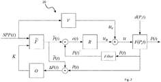
- the wind farm controller 20 is in Fig. 2 shown schematically.
- the input variable SPP (t) forms a setpoint input, which is converted via the feedforward control V into a precontrol control variable u V.
- the predetermined desired value SPP (t) is applied to a model of the wind farm F.
- the model of the wind farm generates a modeled active power setpoint P (t). This modeled active power setpoint is subtracted by a subtraction element from the actual value of the active power P (t), so that a control deviation e (t) arises.
- a filtered value P (t) * of the actual value of the active power P (t) is applied to the abovementioned subtraction element instead of the actual value of the active power P (t).
- the filtered value can be provided by a suitable filter which is provided to smooth short-term, ie high-frequency fluctuations of an actual value of the active power P (t) applied to the filter.
- the control deviation e (t) is due to a power controller R, which generates a controller control variable u R.
- Both manipulated variables are added by an addition element to a total manipulated variable u, which is applied as setpoint to the wind farm F (P, t) as a controlled system.
- the wind farm is analogous to Fig.
- the actual value of the wind farm active power P (t) is also applied to a further subtraction element, to which the modeled active power setpoint P (t) is applied.
- the subtraction element provides an active power difference ⁇ P (t) of the actual and setpoint values.
- the difference between the two active power values ⁇ P (t) is applied to a correction module O.
- the correction module O generates a correction value K, which is applied to the model of the wind farm F.
- the correction values K change the setting of the model F such that the quantity ⁇ P (t) becomes zero.
- the delivered active power values can be guided closer to the desired values SPP (t), in particular overshoots can be avoided. Since the observer O is provided to emulate the behavior of the wind farm as exactly as possible, it makes sense to provide an unfiltered value of the wind farm active power P (t) for the formation of ⁇ P (t).
- a total active power setpoint SPP (t) is passed over an additional path on the actual power controller. This results in the pilot control V a Vor Kunststoffstellish u V. Together with the controller manipulated variable u R , the total manipulated variable u is determined additively.
- Jumps that occur in the setpoint are fed directly to the controlled system via the feedforward control and in this case to the wind farm F (P, t).
- the increased set point on the actuator in this way leads to a potentially shorter control time.
- the internal model F is used. Before the control deviation e (t) is formed, the desired value SPP (t) is given to a model of the controlled system F.
- Fig. 3 shows the course of the target value of the active power of a wind farm 30 over time, as well as the course of the actual value of the active power of the wind farm 31 using a simple feedforward Fig. 1 and the course of the actual value of the active power of the wind farm 32 according to Fig. 2 or with the control method according to the invention based on a pilot control and a wind farm model.
- the horizontal time axis is plotted in seconds, the vertical axis for the active power is plotted in arbitrary units.
- the setpoint SPP (t) 30 increases linearly from the value 1 to the value 2 approximately at the time 80, where it remains constant until approximately the time 200.
- Fig. 3 also shows the influence of the feedforward control and the use of the wind farm model on the setpoint course 32. It can be clearly seen that the actual value 32 achieved with the feedforward control clearly follows the setpoint value 30 in the linear gradient range. It can also be seen that only a very small overshoot occurs during the transition of the setpoint value to the plateau value 2 in that the provided active power of the wind farm is greater than the predetermined setpoint value.
Landscapes
- Engineering & Computer Science (AREA)
- Power Engineering (AREA)
- Life Sciences & Earth Sciences (AREA)
- Sustainable Development (AREA)
- Sustainable Energy (AREA)
- Chemical & Material Sciences (AREA)
- Combustion & Propulsion (AREA)
- Mechanical Engineering (AREA)
- General Engineering & Computer Science (AREA)
- Wind Motors (AREA)
- Control Of Eletrric Generators (AREA)
Abstract
Description
- Die vorliegende Erfindung betrifft ein Verfahren zur Regelung der Wirkleistungsabgabe eines Windparks ebenso wie einen aus mindestens zwei Windenergieanlagen bestehenden Windpark.
- Mit zunehmendem Einsatz von Windenergieanlagen, sei es an Land oder auf See, wird deren Bedeutung für das elektrische Versorgungsnetz größer. Im Hinblick auf die Einspeisung von Wirkleistung führt dies dazu, dass vorgegebene Sollwerte für die am Netzanschlusspunkt eingespeiste Wirkleistung möglichst exakt eingehalten werden sollen. Dies betrifft sowohl den stationären Zustand, bei dem, ausreichend Wind vorausgesetzt, ein konstanter Betrag an Wirkleistung eingespeist wird, wie auch das dynamische Verhalten, bei dem ein Sollwert für die einzuspeisende Wirkleistung sich zeitlich ändert.
- Aus
DE 10 2014 000 790 A1 ist eine Windparkregelung mit einem verbesserten Sollwertverhalten bekannt geworden. Der Windpark weist einen Parkmaster mit einem Leistungsregler zur Regelung der in dem Windpark enthaltenen Windenergieanlagen auf. Ein Sollwert für die Leistungsabgabe des Windparks liegt an dem Parkmaster an und wird als Sollwertsignal für die Leistungsabgabe der Windenergieanlagen ausgegeben. Die Sollwerte für die Windenergieanlagen werden bei einer Änderung des Sollwertsignals für den Windpark korrigiert, wobei der korrigierte Sollwert auf den Leistungsregler aufgeschaltet ist. Mit einem Prädiktor wird der Sollwert für die Windenergieanlage berechnet, wobei hier unterschiedliche Betriebszustände der Windenergieanlagen und unterschiedlich produzierte Leistung berücksichtigt werden. - Aus
DE 10 2014 000 784 A1 ist ein Windpark mit Vorsteuerung im Leistungsregler bekannt geworden. Der Windpark besitzt einen Parkmaster, der zur Führung der Windenergieanlagen ausgebildet ist, wobei der Parkmaster einen Leistungsregler umfasst. Der Leistungsregler besitzt ein Vorsteuermodul, das ein Maß für die Sollleistung über ein Multiplikationsglied auf den Ausgang des Leistungsreglers aufschaltet. Hierdurch soll ein beschleunigtes Ansprechverhalten der Vorsteuerung bei einer Sollwertreduktion erzielt werden und ein gegenüber dem Betriebszustand des Windparks robustes Ansprechverhalten geschaffen werden. - Der Erfindung liegt die Aufgabe zugrunde, ein Regelungsverfahren für einen Windpark sowie einen Windpark anzugeben, die sowohl im stationären als auch im transienten Verhalten einer Sollwertvorgabe möglichst genau folgen.
- Erfindungsgemäß wird die Aufgabe durch ein Verfahren mit den Merkmalen aus Anspruch 1 sowie einen Windpark mit den Merkmalen aus Anspruch 7 gelöst. Vorteilhafte Ausgestaltungen bilden die Gegenstände der Unteransprüche.
- Das erfindungsgemäße Verfahren ist vorgesehen und bestimmt zur Regelung der Wirkleistungsabgabe eines Windparks mit mindestens zwei Windenergieanlagen, die Wirkleistung in ein Versorgungsnetz einspeisen. Ein Sollwert für die durch den Windpark abzugebende Wirkleistung liegt an einem Windparkmodell an, das einen modellierten Wirkleistungssollwert ermittelt. Der modellierte Wirkleistungssollwert bildet zusammen mit einem Istwert der Wirkleistung eine Regelabweichung für einen Leistungsregler. Zu einer Reglerstellgröße des Windparkreglers wird additiv eine Vorsteuerstellgröße hinzu addiert. Die Vorsteuerstellgröße ist unabhängig von Zuständen des Windparks und seinen Istwerten und hängt lediglich von dem Sollwert für die Wirkleistung des Windparks ab. Aus der Reglerstellgröße und der Vorsteuerstellgröße wird durch Addition eine Gesamtstellgröße für den Windpark gebildet.
- Erfindungsgemäß wird eine Differenz aus dem Istwert der Wirkleistung und dem modellierten Wirkleistungssollwert bestimmt. Aus der Differenz wird ein Korrekturwert für die Bestimmung des modellierten Wirkleistungssollwerts erzeugt. Die Erfindung beruht auf der Erkenntnis, dass sich der modellierte Wirkleistungssollwert des Windparks abhängig von einer Abweichung vom Istwert der Wirkleistung und dem modellierten Wirkleistungssollwert korrigieren lässt, so dass Abweichungen im Modell, bedingt durch Betriebs- und Arbeitspunkte der Windenergieanlagen im Park ausgeglichen werden können. Das Modell erzeugt mit dem modellierten Wirkleistungssollwert, den Wert für die Wirkleistung, die der Windpark, ansprechend auf die Sollwertvorgabe, einspeisen würde. Bevorzugt kann durch diese Korrektur ein genaueres Anregelverhalten des Windparks erreicht werden, welcher externen Sollwertvorgaben dann genauer folgen kann. Rückwirkungen auf ein elektrisches Versorgungsnetz, in das der Windpark Leistung einspeist, können somit effektiv minimiert werden.
- In einer bevorzugten Ausgestaltung minimiert der Korrekturwert eine Abweichung zwischen dem modellierten Wirkleistungssollwert und dem Istwert der Wirkleistung des Windparks. Dadurch dass der Korrekturwert auf der Differenz zwischen dem modellierten Wirkleistungssollwert und dem Istwert beruht, hängt der Korrekturwert von den Abweichungen des Modells vom realen Verhalten des Windparks bzw. der einzelnen Windenergieanlagen des Windparks ab. Liegt keine Abweichung vor, so ist der Korrekturwert Null und es erfolgt keine Korrektur des Modells.
- In einer bevorzugten Ausgestaltung ist der Leistungsregler zum Ausregeln von Störungen ausgelegt. Durch die Vorsteuerung folgt der Istwert direkt dem Sollwert und der Leistungsregler kann zum Ausregeln von Störungen optimiert werden.
- In einer weiteren bevorzugten Ausgestaltung wird mit dem Korrekturwert eine Abhängigkeit des modellierten Wirkleistungssollwertes von einem Betriebspunkt des Windparks korrigiert. Das dem modellierten Wirkleistungssollwert zugrundeliegende Modell des Windparks ist weitestgehend von einem Betriebspunkt, wie beispielsweise dem Istwert der eingespeisten Wirkleistung, unabhängig. Durch den Korrekturwert kann eine verbleibende Abhängigkeit von dem Betriebspunkt in dem Modell aufgelöst werden.
- In einer bevorzugten Ausgestaltung ist das Verfahren so ausgelegt, dass im eingeschwungenen Zustand, wenn der modellierte Wirkleistungssollwert und der Istwert der Wirkleistung übereinstimmen, die Gesamtstellgröße den Wert Null annimmt. Indem dann die Gesamtstellgröße den Wert Null aufweist, erfolgt ein Ausregeln der in dem Windpark auftretenden Störungen. Eine Übertragungsfunktion der Führungsgröße ist damit von der Störübertragungsfunktion entkoppelt.
- In einer bevorzugten Ausgestaltung werden Filter, beispielsweise zur zeitlichen Glättung des modellierten Wirkleistungssollwerts als auch des Istwerts für die Wirkleistung eingesetzt.
- Die erfindungsgemäße Aufgabe wird ebenfalls durch einen Windpark mit den Merkmalen aus Anspruch 7 gelöst.
- Der erfindungsgemäße Windpark weist mindestens zwei Windenergieanlagen und einen Windparkregler auf. Der Windparkregler besitzt einen Leistungsregler, der eine Reglerstellgröße für die Wirkleistung des Windparks bildet. Eine Vorsteuerung ist vorgesehen, die unabhängig von Zuständen des Windparks und seinen Istwerten eine Vorsteuerstellgröße bildet. Ferner ist ein Modell vorgesehen, das aus einem Sollwert für die Wirkleistung des Windparks einen modellierten Wirkleistungssollwert bestimmt. Der modellierte Wirkleistungssollwert liegt an einem Leistungsregler an, der eine Reglerstellgröße ausgibt. In dem erfindungsgemäßen Windparkregler wird die Vorsteuerstellgröße additiv zu der Reglerstellgröße an den Leistungsregler angelegt. In dem Windparkregler ist ferner ein Korrekturmodul vorgesehen, an dem eine Differenz von modelliertem Wirkleistungssollwert und Istwert der Wirkleistung anliegt. Das Korrekturmodul ermittelt einen Korrekturwert für das Modell, mit dem der modellierte Wirkleistungssollwert bestimmt wird. Der besondere Vorteil an dem Windpark und seinem Windparkregler liegt darin, dass der Leistungsregler auf ein Ausregeln von Störgrößen ausgelegt werden kann, während die Vorsteuerung Änderungen in dem Sollwert ausgleicht. Zudem wird durch den Korrekturwert eine Abweichung zwischen dem modellierten Wirkleistungssollwert und dem Istwert der Wirkleistung minimiert. Insbesondere auch bei transienten Zuständen des Windparks, bei denen der Sollwert der einzuspeisenden Wirkleistung sich sprunghaft oder entlang einer Rampe geändert hat, kann durch den Korrekturwert das Modell zur Bestimmung des modellierten Wirkleistungssollwerts angepasst werden. Die Vorsteuerung führt den Windpark entlang dem Sollwert, während der Leistungsregler so ausgelegt ist, dass Störgrößen bei der Bereitstellung der Wirkleistung durch den Windpark ausgeglichen werden.
- In einer bevorzugten Ausgestaltung sind ein oder mehrere Filter für den modellierten Wirkleistungssollwert und/oder den Istwert der Wirkleistung vorgesehen. Über die Filter können beispielsweise kurzfristige, d. h. hochfrequente Schwankungen ausgeblendet werden.
- In einer weiter bevorzugten Ausgestaltung teilt der Windparkregler die gesamte Stellgröße auf Einzelstellgrößen für Leistungsregler der in dem Windpark enthaltenen Windenergieanlagen auf. Die Aufteilung kann dabei spezifische Größen der Windenergieanlagen, wie beispielsweise Istwerte der Leistung, Regelungsreserve, erfasste Windgeschwindigkeit berücksichtigen.
- Die Erfindung wird nachfolgend an einem bevorzugten Ausführungsbeispiel erläutert. Es zeigen:
- Fig. 1
- eine schematische Ansicht eines Windparkreglers mit einfacher Vorsteuerung,
- Fig. 2
- eine schematische Ansicht eines Windparkreglers mit Vorsteuerung und Modell des Windparks, und
- Fig. 3
- einen beispielhaften Verlauf der Wirkleistung mit Vorsteuerung mit und ohne Modell.
-
Fig. 1 zeigt eine schematische Ansicht eines Windparkreglers 10 mit einfacher Vorsteuerung. Die Eingangsgröße bildet der zeitabhängig vorgegebene Sollwert SPP(t) für die abzugebende Wirkleistung. Der Sollwert liegt an einer Vorsteuerung V an, die hieraus eine Vorsteuerstellgröße uV ermittelt. Gleichzeitig liegt der zeitabhängige Sollwert SPP(t) zusammen mit dem Istwert der Wirkleistung P(t) an einem Subtraktionsglied an, das eine Regelabweichung e(t) bildet. Die Regelabweichung e(t) liegt an einem Leistungsregler R an. Dieser erzeugt eine Reglerstellgröße uR. Ausgangsgröße des Leistungsregler R ist die Reglerstellgröße uR. Die Vorsteuerstellgröße uV und die Reglerstellgröße uR liegen an einem Additionsglied an und werden durch dieses zu einer Gesamtstellgröße u addiert. Die Gesamtstellgröße u liegt an der Regelstrecke F(P,t) an. Die Regelstrecke bildet hierbei der Windpark, wobei die Gesamtstellgröße u auf die einzelnen Windenergieanlagen im Windpark aufgeteilt wird. Die Aufteilung kann beispielsweise anhand einer von den einzelnen Windenergieanlagen als verfügbar gemeldete Wirkleistung erfolgen. Für die Beschreibung der Ausführungsbeispiele kann davon ausgegangen werden, dass eine geeignete Aufteilung in der Regelstrecke F(P,t) umfasst ist. - Der erfindungsgemäße Windparkregler 20 ist in
Fig. 2 schematisch dargestellt. Die Eingangsgröße SPP(t) bildet eine Sollwertvorgabe, die über die Vorsteuerung V in eine Vorsteuerregelgröße uV umgesetzt wird. Zugleich liegt der vorgegebene Sollwert SPP(t) an einem Modell des Windparks F̃ an. Das Modell des Windparks erzeugt einen modellierten Wirkleistungssollwert P̃(t). Dieser modellierte Wirkleistungssollwert wird durch ein Subtraktionsglied von dem Istwert der Wirkleistung P(t) subtrahiert, so dass ein Regelabweichung e(t) entsteht. In einer bevorzugten Ausführung liegt an dem zuvor genannten Subtraktionsglied anstelle des Istwerts der Wirkleistung P(t) ein gefilterter Wert P(t)* des Istwerts der Wirkleistung P(t) an. Der gefilterte Wert kann von einem geeigneten Filter bereitgestellt werden, der vorgesehen ist, kurzfristige, d. h. hochfrequente Schwankungen eines an dem Filter anliegenden Istwerts der Wirkleistung P(t) zu glätten. Der Regelabweichung e(t) liegt an einem Leistungsregler R, der eine Reglerstellgröße uR erzeugt. Beide Stellgrößen werden durch ein Additionsglied zu einer Gesamtstellgröße u addiert, die als Sollwert an dem Windpark F(P,t) als Regelstrecke anliegt. Der Windpark setzt, analog zuFig. 1 , die Gesamtstellgröße u in die abzugebende Wirkleistung P(t) um. Bei diesem Ansatz mit einer Vorsteuerung werden Störgrößen d(P,t) direkt über den Leistungsregler R ausgeregelt. Als typische Störgrößen seien beispielsweise zeitliche Änderungen in Windgeschwindigkeit und/oder Windrichtung genannt, die das Verhalten der einzelnen Windenergieanlagen des Windparks beeinflussen. - Der Istwert der Windpark-Wirkleistung P(t) liegt ebenfalls an einem weiteren Subtraktionsglied an, an dem auch der modellierte Wirkleistungssollwert P̃ (t) anliegt. Das Subtraktionsglied stellt eine Wirkleistungsdifferenz ΔP(t) von Ist- und Sollwert bereit. Die Differenz beider Wirkleistungswerte ΔP(t) liegt an einem Korrekturmodul O an. Das Korrekturmodul O erzeugt einen Korrekturwert K, der an dem Modell des Windparks F̃ anliegt. Die Korrekturwerte K verändern die Einstellung des Modells F̃ derart, dass die Größe ΔP(t) zu Null wird. Durch das Modell des Windparks F̃, das eine inverse Regelungsstrecke für die Wirkleistungsregelung des Windparks nachbildet und das Korrekturmodell O können die abgegebenen Wirkleistungswerte näher an den Sollwerten SPP(t) geführt werden, insbesondere können Überschwinger vermieden werden. Da der Beobachter O vorgesehen ist, dass Verhalten des Windparks möglichst exakt nachzubilden, ist es sinnvoll, für die Bildung von ΔP(t) einen ungefilterten Wert der Windpark-Wirkleistung P(t) bereitzustellen.
- Bei dem Regelungsverfahren wird insgesamt ein Wirkleistungssollwert SPP(t) über einen zusätzlichen Pfad am eigentlichen Leistungsregler vorbeigeführt. Dadurch ergibt sich über die Vorsteuerung V eine Vorsteuerstellgröße uV. Zusammen mit der Reglerstellgröße uR wird additiv die Gesamtstellgröße u ermittelt.
- Sprünge, die im Sollwert auftreten, werden über die Vorsteuerung direkt auf die Regelstrecke und in diesem Fall auf den Windpark F(P,t) gegeben. Der erhöhte Sollwert an dem Stellglied führt auf diese Weise zu einer potenziell kürzeren Regelzeit.
- Für ein verbessertes Einschwenkverhalten auf einen Plateauwert wird das interne Modell F̃ verwendet. Vor Bildung der Regelabweichung e(t) wird der Sollwert SPP(t) auf ein Modell der Regelstrecke F̃ gegeben. Die Regelabweichung e(t) ergibt sich also durch:

- Ist das Modell identisch mit der realen (inversen) Regelstrecke, so ist im eingeschwungenen Zustand der Ausgang des Leistungsreglers uR = 0. Ändert sich der Sollwert SPP(t) und ist das zeitliche Verhalten von F(P,t) und F̃(P,t) identisch, so bleibt die Regelabweichung weiterhin bei null. Dies bedeutet, die Dynamik des Reglers hat keinen Einfluss auf das Führungsverhalten.
- Da der Windpark als Strecke nicht exakt abgebildet werden kann und sich das Übertragungsverhalten in Abhängigkeit des Betriebspunktes der einzelnen Windenergieanlagen ändert, muss ein Fehler des Modells kompensiert werden. Hierzu wird ein Modellfehler für eine konstante Korrekturfunktion O auf das Modell zurückgekoppelt. Der Einfluss von Störgrößen d(P,t) im Windpark führt zu einer Regelabweichung e(t), die durch den Leistungsregler ausgeglichen wird.
- Durch das Verfahren der Vorsteuerung ist es möglich, die Führungsübertragungsfunktion von der Störübertragungsfunktion zu entkoppeln. Die Regelgröße folgt direkt dem Sollwert und der Leistungsregler kann auf die Ausregelung von Störungen optimiert werden. Sollwertvorgaben kann damit insgesamt exakter gefolgt und Abweichungen im stationären Zustand vermieden werden. Dabei wird die Ausregelzeit reduziert.
-
Fig. 3 zeigt den Verlauf des Sollwerts der Wirkleistung eines Windparks 30 über der Zeit, sowie den Verlauf des Istwerts der Wirkleistung des Windparks 31 unter Verwendung einer einfachen Vorsteuerung nachFig. 1 und den Verlauf des Istwerts der Wirkleistung des Windparks 32 gemäßFig. 2 bzw. mit dem erfindungsgemäßen Regelungsverfahren basierend auf einer Vorsteuerung und einem Windparkmodell. Die horizontale Zeitachse ist in Sekunden aufgetragen, die vertikale Achse für die Wirkleistung ist in beliebigen Einheiten aufgetragen. Die Sollwertvorgabe SPP(t) 30 steigt ungefähr zum Zeitpunkt 80 linear von dem Wert 1 auf den Wert 2 an, wo sie weiter konstant bis ungefähr zum Zeitpunkt 200 bleibt. Deutlich zu erkennen ist, dass in dem Bereich, in dem der Sollwert der Wirkleistung 30 von 1 auf 2 ansteigt, der Istwert der Wirkleistung mit einfacher Vorsteuerung 31 deutlich unter dem Sollwert zurückbleibt.Fig. 3 zeigt ebenfalls den Einfluss der Vorsteuerung und der Verwendung des Windparkmodells auf den Sollwertverlauf 32. Deutlich zu erkennen ist, dass der mit der Vorsteuerung erzielte Istwert 32 im linearen Steigungsbereich deutlich dem Sollwert 30 folgt. Auch zu erkennen ist, dass beim Übergang des Sollwerts auf den Plateauwert 2 lediglich ein sehr geringer Überschwinger auftritt, indem die bereitgestellte Wirkleistung des Windparks größer als der vorgegebene Sollwert ist. -
- 10
- Windparkregler
- 20
- Windparkregler
- O
- Korrekturmodul
- R
- Leistungsregler
- F̃
- Modell des Windparks
- V
- Vorsteuerung
- F(P,t)
- Regelstrecke
- SPP(t)
- vorgegebener Wirkleistungssollwert des Windparks
- P̃(t)
- modellierter Wirkleistungssollwert
- P(t)
- Istwert der Wirkleistung des Windparks
- P(t)*
- gefilterter Istwert der Wirkleistung des Windparks
- e(t)
- Regelabweichung
- ΔP(t)
- Wirkleistungsdifferenz
- K
- Korrekturwert
- uV
- Vorsteuerstellgröße
- uR
- Reglerstellgröße
- u
- Gesamtstellgröße für den Wirkleistungssollwert des Windparks
- d(P,t)
- Störgröße
- 30
- Sollwerts der Wirkleistung eines Windparks (SPP(t))
- 31
- Istwerts der Wirkleistung des Windparks (P(t)) mit einfacher Vorsteuerung
- 32
- Istwerts der Wirkleistung des Windparks (P(t)) mit Vorsteuerung und Windparkmodell|[HA1]
Claims (11)
- Verfahren zur Regelung einer Wirkleistung in einem Windpark (F(P,t)) mit mindestens zwei Wirkleistung einspeisenden Windenergieanlagen, wobei ein Sollwert für die Wirkleistung (SPP(t)) des Windparks an einem Windparkmodell (F̃) anliegt, das einen modellierten Wirkleistungssollwert (P̃(t)) ermittelt, der zusammen mit einem Istwert der Wirkleistung (P(t)) eine Regelabweichung (e(t)) für einen Leistungsregler (R) bildet, dessen Reglerstellgröße (uR) additiv mit einer unabhängig von Zuständen des Windparks (F(P,t)) und von seinen Istwerten bestimmten Vorsteuerstellgröße (uV) beaufschlagt wird, und eine Gesamtstellgröße (u) für den Windpark (F(P,t)) bildet,
dadurch gekennzeichnet, dass
ein Korrekturwert (K) für die Bestimmung des modellierten Leistungssollwerts (P̃(t)), abhängig von einer Differenz aus dem Istwert der Wirkleistung (P(t)) und dem modellierten Wirkleistungssollwert (P̃ (t)), von einem Korrekturmodul (O) erzeugt wird und an dem Windparkmodell (F̃) anliegt. - Verfahren nach Anspruch 1, dadurch gekennzeichnet, dass der Korrekturwert (K) von dem Korrekturmodul (O) so erzeugt wird, dass eine Abweichung zwischen dem modellierten Wirkleistungssollwert (P̃(t)) und dem Istwert der Wirkleistung (P(t)) minimiert wird.
- Verfahren nach Anspruch 1 oder 2, dadurch gekennzeichnet, dass der Leistungsregler (R) zum Ausregeln von Störungen (d(P,t)) ausgelegt ist.
- Verfahren nach einem der Ansprüche 1 bis 3, dadurch gekennzeichnet, dass mit dem Korrekturwert (K) eine Abhängigkeit des modellierten Wirkleistungssollwerts (P̃(t)) von einem Betriebspunkt des Windparks (F(P,t)) korrigiert wird.
- Verfahren nach einem der Ansprüche 1 bis 4, dadurch gekennzeichnet, dass im eingeschwungenen Zustand, wenn der modellierte Wirkleistungssollwert (P̃ (t)) und der Istwert der Wirkleistung (P(t)) übereinstimmen, die Reglerstellgröße (uR) verschwindet.
- Verfahren nach einem der Ansprüche 1 bis 5, dadurch gekennzeichnet, dass der modellierte Wirkleistungssollwert (P̃(t)) und/oder der Istwert für die Wirkleistung (P(t)) gefiltert werden.
- Windpark (F(P,t)) mit mindestens zwei Windenergieanlagen und einem Windparkregler (20), der einen Leistungsregler (R), der eine Reglerstellgröße (uR) für die von dem Windpark (F(P,t)) abzugebende Wirkleistung bildet, eine Vorsteuerung (V), die unabhängig von Zuständen des Windparks (F(P,t)) und seinen Istwerten eine Vorsteuerstellgröße (uV) ermittelt, und ein Modell (F̃) aufweist, das aus einem Sollwert für die Wirkleistung (SPP(t)) für den Windpark (F(P,t)) einen modellierten Wirkleistungssollwert (P̃(t)) bestimmt, wobei die Vorsteuerstellgröße (uV) additiv zu der Reglerstellgröße (uR) an dem Leistungsregler (R) anliegt,
dadurch gekennzeichnet, dass
ein Korrekturmodul (O) vorgesehen ist, an dem eine Differenz von modelliertem Wirkleistungswert (P̃ (t)) und Istwert der Wirkleistung (P(t)) anliegt und das einen Korrekturwert (K) für das Modell (F̃) bereitstellt. - Windpark nach Anspruch 7, dadurch gekennzeichnet, dass der Korrekturwert (K) eine Abweichung des modellierten Wirkleistungssollwerts (P̃(t)) von dem Istwert der Wirkleistung (P(t)) minimiert.
- Windpark nach Anspruch 7 oder 8, dadurch gekennzeichnet, dass der Leistungsregler (R) ausgelegt ist, um Störungen (d(P,t)) auszugleichen.
- Windpark nach einem der Ansprüche 7 bis 9, dadurch gekennzeichnet, dass ein oder mehrere Filter für den modellierten Wirkleistungswert (P̃(t)) und/oder den Istwert der Wirkleistung (P(t)) vorgesehen sind.
- Windpark nach einem der Ansprüche 7 bis 10, dadurch gekennzeichnet, dass der Windparkregler (20) die Gesamtstellgröße (u) auf Einzelstellgrößen für Leistungsregler der Windenergieanlagen aufteilt.
Priority Applications (4)
| Application Number | Priority Date | Filing Date | Title |
|---|---|---|---|
| ES17160518T ES2913122T3 (es) | 2017-03-13 | 2017-03-13 | Método de control del suministro de potencia activa de un parque eólico, y dicho parque eólico |
| DK17160518.1T DK3376626T3 (da) | 2017-03-13 | 2017-03-13 | Fremgangsmåde til regulering af virkeeffekt fra en vindmøllepark, og en sådan vindmøllepark |
| EP17160518.1A EP3376626B1 (de) | 2017-03-13 | 2017-03-13 | Verfahren zur regelung der wirkleistungsabgabe eines windparks sowie ein solcher windpark |
| US15/919,587 US10393092B2 (en) | 2017-03-13 | 2018-03-13 | Method and system for controlling the active power output of a wind farm |
Applications Claiming Priority (1)
| Application Number | Priority Date | Filing Date | Title |
|---|---|---|---|
| EP17160518.1A EP3376626B1 (de) | 2017-03-13 | 2017-03-13 | Verfahren zur regelung der wirkleistungsabgabe eines windparks sowie ein solcher windpark |
Publications (2)
| Publication Number | Publication Date |
|---|---|
| EP3376626A1 true EP3376626A1 (de) | 2018-09-19 |
| EP3376626B1 EP3376626B1 (de) | 2022-02-09 |
Family
ID=58314127
Family Applications (1)
| Application Number | Title | Priority Date | Filing Date |
|---|---|---|---|
| EP17160518.1A Active EP3376626B1 (de) | 2017-03-13 | 2017-03-13 | Verfahren zur regelung der wirkleistungsabgabe eines windparks sowie ein solcher windpark |
Country Status (4)
| Country | Link |
|---|---|
| US (1) | US10393092B2 (de) |
| EP (1) | EP3376626B1 (de) |
| DK (1) | DK3376626T3 (de) |
| ES (1) | ES2913122T3 (de) |
Cited By (2)
| Publication number | Priority date | Publication date | Assignee | Title |
|---|---|---|---|---|
| DE102019131475A1 (de) * | 2019-11-21 | 2021-05-27 | TenneT TSO GmbH | Verfahren zur Stromregelung eines Energiesystems |
| CN113515046A (zh) * | 2021-07-19 | 2021-10-19 | 西安理工大学 | 一种基于前馈控制的卷筒料涂布机收卷张力控制方法 |
Families Citing this family (4)
| Publication number | Priority date | Publication date | Assignee | Title |
|---|---|---|---|---|
| EP3444938B1 (de) * | 2017-08-18 | 2020-11-18 | Nordex Energy GmbH | Verfahren zur steuerung einer windenergieanlage |
| DK3444939T3 (da) * | 2017-08-18 | 2021-03-08 | Nordex Energy Se & Co Kg | Fremgangsmåde til styring af et vindenergianlæg |
| CN112215425B (zh) * | 2020-10-16 | 2023-10-20 | 国网冀北电力有限公司 | 风电集群有功功率的调度方法及装置 |
| CN119664578B (zh) * | 2025-02-21 | 2025-05-30 | 湖南大学 | 一种风电场双模式动态主动尾流控制方法、系统及介质 |
Citations (2)
| Publication number | Priority date | Publication date | Assignee | Title |
|---|---|---|---|---|
| DE102014000790A1 (de) | 2014-01-22 | 2015-07-23 | Senvion Se | Windparkregelung mit verbessertem Sollwertsprungverhalten |
| DE102014000784A1 (de) | 2014-01-22 | 2015-07-23 | Senvion Se | Windpark mit Vorsteuerung im Leistungsregler |
Family Cites Families (5)
| Publication number | Priority date | Publication date | Assignee | Title |
|---|---|---|---|---|
| US6600240B2 (en) * | 1997-08-08 | 2003-07-29 | General Electric Company | Variable speed wind turbine generator |
| DK1467463T3 (en) * | 2003-04-09 | 2017-03-27 | Gen Electric | Wind farm and method for operating it |
| US20090055030A1 (en) * | 2007-08-21 | 2009-02-26 | Ingeteam, S.A. | Control of active power reserve in a wind-farm |
| EP2328259B2 (de) * | 2008-08-12 | 2024-01-03 | Ingeteam Power Technology, S.A. | System und verfahren zum powermanagement in einer photovoltaikinstallation |
| IN2013CH06082A (de) * | 2013-12-26 | 2015-07-03 | Gen Electric |
-
2017
- 2017-03-13 ES ES17160518T patent/ES2913122T3/es active Active
- 2017-03-13 EP EP17160518.1A patent/EP3376626B1/de active Active
- 2017-03-13 DK DK17160518.1T patent/DK3376626T3/da active
-
2018
- 2018-03-13 US US15/919,587 patent/US10393092B2/en active Active
Patent Citations (2)
| Publication number | Priority date | Publication date | Assignee | Title |
|---|---|---|---|---|
| DE102014000790A1 (de) | 2014-01-22 | 2015-07-23 | Senvion Se | Windparkregelung mit verbessertem Sollwertsprungverhalten |
| DE102014000784A1 (de) | 2014-01-22 | 2015-07-23 | Senvion Se | Windpark mit Vorsteuerung im Leistungsregler |
Cited By (3)
| Publication number | Priority date | Publication date | Assignee | Title |
|---|---|---|---|---|
| DE102019131475A1 (de) * | 2019-11-21 | 2021-05-27 | TenneT TSO GmbH | Verfahren zur Stromregelung eines Energiesystems |
| DE102019131475B4 (de) | 2019-11-21 | 2022-03-03 | TenneT TSO GmbH | Verfahren zur Leistungsregelung eines Offshore-Windenergiesystems mittels eines Zweipunktreglers mit Hysteresefunktion |
| CN113515046A (zh) * | 2021-07-19 | 2021-10-19 | 西安理工大学 | 一种基于前馈控制的卷筒料涂布机收卷张力控制方法 |
Also Published As
| Publication number | Publication date |
|---|---|
| DK3376626T3 (da) | 2022-04-25 |
| US10393092B2 (en) | 2019-08-27 |
| EP3376626B1 (de) | 2022-02-09 |
| ES2913122T3 (es) | 2022-05-31 |
| US20180258913A1 (en) | 2018-09-13 |
Similar Documents
| Publication | Publication Date | Title |
|---|---|---|
| EP3376626B1 (de) | Verfahren zur regelung der wirkleistungsabgabe eines windparks sowie ein solcher windpark | |
| DE3207392C2 (de) | Vorrichtung zur selbstanpassenden Stellungsregelung eines Stellgliedes | |
| DE3650164T2 (de) | Prozessregler mit einem System zur Einstellung mit zwei Freiheitsgraden. | |
| DE3311048C2 (de) | Einrichtung zur Verfahrensregelung | |
| EP2258939B1 (de) | Verfahren zur Regelung der Temperatur einer Glühkerze | |
| DE3023550A1 (de) | Steuersystem zur steuerung der kraftstoffzufuhr bei einer gasturbine | |
| DE2931446C2 (de) | Einrichtung zur Regelung der vom Generator eines Wasserkraftmaschinensatzes erzeugten Wirkleistung | |
| DE2702774A1 (de) | Vorrichtung zur drehzahlregelung von turbo-luftstrahltriebwerken | |
| DE2025528C3 (de) | Regeleinrichtung für eine Dampfturbinen-Kraftanlage | |
| EP1423594A1 (de) | Verfahren und vorrichtung zum ansteuern piezobetriebener kraftstoff-einspritzventile | |
| EP3429050A1 (de) | Verfahren zur regelung der wirkleistungsabgabe eines windparks sowie ein entsprechender windpark | |
| EP3097622B1 (de) | Windparkregelung mit verbessertem sollwertsprungverhalten | |
| EP3542229B1 (de) | Einrichtung und verfahren zur bestimmung der parameter einer regeleinrichtung | |
| EP0473914B1 (de) | System zur Regelung eines Stellwerks in einem Kraftfahrzeug | |
| DE2600427A1 (de) | Selbstanpassendes regelungssystem, das sich entsprechend den eigenschaften seines regelkreises auf eine optimale ausbildung selbsttaetig einstellt | |
| WO2005050832A1 (de) | Verstärker mit endstufen-gesteuerter regelung | |
| EP1490735B1 (de) | Verfahren und regler zur adaptiven regelung mindestens einer komponente einer technischen anlage | |
| EP3376026A1 (de) | Verfahren zur regelung der wirkleistungsabgabe eines windparks sowie ein entsprechender windpark | |
| CH679235A5 (de) | ||
| DE1538558B2 (de) | Redundante elektrische signaluebertragungseinrichtung fuer steuer oder regelkreise | |
| DE102019100718A1 (de) | Sensorlose steuerung eines elektromotors | |
| DE1523535B2 (de) | Selbstanpassender Regelkreis | |
| DE3541148C3 (de) | Verfahren zur Regelung einer Dampfturbine | |
| DE69501938T2 (de) | Desensibilisierte Regelvorrichtung für die Statorspannung eines Wechselstromgenerators | |
| DE102016203123A1 (de) | Vorrichtung und Verfahren zur Regelung eines Wechselrichters |
Legal Events
| Date | Code | Title | Description |
|---|---|---|---|
| PUAI | Public reference made under article 153(3) epc to a published international application that has entered the european phase |
Free format text: ORIGINAL CODE: 0009012 |
|
| STAA | Information on the status of an ep patent application or granted ep patent |
Free format text: STATUS: THE APPLICATION HAS BEEN PUBLISHED |
|
| AK | Designated contracting states |
Kind code of ref document: A1 Designated state(s): AL AT BE BG CH CY CZ DE DK EE ES FI FR GB GR HR HU IE IS IT LI LT LU LV MC MK MT NL NO PL PT RO RS SE SI SK SM TR |
|
| AX | Request for extension of the european patent |
Extension state: BA ME |
|
| STAA | Information on the status of an ep patent application or granted ep patent |
Free format text: STATUS: REQUEST FOR EXAMINATION WAS MADE |
|
| 17P | Request for examination filed |
Effective date: 20190305 |
|
| RBV | Designated contracting states (corrected) |
Designated state(s): AL AT BE BG CH CY CZ DE DK EE ES FI FR GB GR HR HU IE IS IT LI LT LU LV MC MK MT NL NO PL PT RO RS SE SI SK SM TR |
|
| STAA | Information on the status of an ep patent application or granted ep patent |
Free format text: STATUS: EXAMINATION IS IN PROGRESS |
|
| 17Q | First examination report despatched |
Effective date: 20200408 |
|
| RAP1 | Party data changed (applicant data changed or rights of an application transferred) |
Owner name: NORDEX ENERGY SE & CO. KG |
|
| RIC1 | Information provided on ipc code assigned before grant |
Ipc: H02J 3/48 20060101ALN20210311BHEP Ipc: H02J 3/46 20060101ALI20210311BHEP Ipc: H02J 3/38 20060101AFI20210311BHEP |
|
| GRAP | Despatch of communication of intention to grant a patent |
Free format text: ORIGINAL CODE: EPIDOSNIGR1 |
|
| STAA | Information on the status of an ep patent application or granted ep patent |
Free format text: STATUS: GRANT OF PATENT IS INTENDED |
|
| INTG | Intention to grant announced |
Effective date: 20210422 |
|
| GRAJ | Information related to disapproval of communication of intention to grant by the applicant or resumption of examination proceedings by the epo deleted |
Free format text: ORIGINAL CODE: EPIDOSDIGR1 |
|
| STAA | Information on the status of an ep patent application or granted ep patent |
Free format text: STATUS: EXAMINATION IS IN PROGRESS |
|
| INTC | Intention to grant announced (deleted) | ||
| RIC1 | Information provided on ipc code assigned before grant |
Ipc: H02J 3/48 20060101ALN20210809BHEP Ipc: H02J 3/46 20060101ALI20210809BHEP Ipc: H02J 3/38 20060101AFI20210809BHEP |
|
| GRAP | Despatch of communication of intention to grant a patent |
Free format text: ORIGINAL CODE: EPIDOSNIGR1 |
|
| STAA | Information on the status of an ep patent application or granted ep patent |
Free format text: STATUS: GRANT OF PATENT IS INTENDED |
|
| INTG | Intention to grant announced |
Effective date: 20210928 |
|
| GRAS | Grant fee paid |
Free format text: ORIGINAL CODE: EPIDOSNIGR3 |
|
| GRAA | (expected) grant |
Free format text: ORIGINAL CODE: 0009210 |
|
| STAA | Information on the status of an ep patent application or granted ep patent |
Free format text: STATUS: THE PATENT HAS BEEN GRANTED |
|
| AK | Designated contracting states |
Kind code of ref document: B1 Designated state(s): AL AT BE BG CH CY CZ DE DK EE ES FI FR GB GR HR HU IE IS IT LI LT LU LV MC MK MT NL NO PL PT RO RS SE SI SK SM TR |
|
| REG | Reference to a national code |
Ref country code: GB Ref legal event code: FG4D Free format text: NOT ENGLISH |
|
| REG | Reference to a national code |
Ref country code: CH Ref legal event code: EP Ref country code: AT Ref legal event code: REF Ref document number: 1468099 Country of ref document: AT Kind code of ref document: T Effective date: 20220215 |
|
| REG | Reference to a national code |
Ref country code: DE Ref legal event code: R096 Ref document number: 502017012558 Country of ref document: DE |
|
| REG | Reference to a national code |
Ref country code: IE Ref legal event code: FG4D Free format text: LANGUAGE OF EP DOCUMENT: GERMAN |
|
| REG | Reference to a national code |
Ref country code: DK Ref legal event code: T3 Effective date: 20220422 |
|
| REG | Reference to a national code |
Ref country code: ES Ref legal event code: FG2A Ref document number: 2913122 Country of ref document: ES Kind code of ref document: T3 Effective date: 20220531 |
|
| REG | Reference to a national code |
Ref country code: LT Ref legal event code: MG9D |
|
| REG | Reference to a national code |
Ref country code: NL Ref legal event code: MP Effective date: 20220209 |
|
| PG25 | Lapsed in a contracting state [announced via postgrant information from national office to epo] |
Ref country code: SE Free format text: LAPSE BECAUSE OF FAILURE TO SUBMIT A TRANSLATION OF THE DESCRIPTION OR TO PAY THE FEE WITHIN THE PRESCRIBED TIME-LIMIT Effective date: 20220209 Ref country code: RS Free format text: LAPSE BECAUSE OF FAILURE TO SUBMIT A TRANSLATION OF THE DESCRIPTION OR TO PAY THE FEE WITHIN THE PRESCRIBED TIME-LIMIT Effective date: 20220209 Ref country code: PT Free format text: LAPSE BECAUSE OF FAILURE TO SUBMIT A TRANSLATION OF THE DESCRIPTION OR TO PAY THE FEE WITHIN THE PRESCRIBED TIME-LIMIT Effective date: 20220609 Ref country code: NO Free format text: LAPSE BECAUSE OF FAILURE TO SUBMIT A TRANSLATION OF THE DESCRIPTION OR TO PAY THE FEE WITHIN THE PRESCRIBED TIME-LIMIT Effective date: 20220509 Ref country code: NL Free format text: LAPSE BECAUSE OF FAILURE TO SUBMIT A TRANSLATION OF THE DESCRIPTION OR TO PAY THE FEE WITHIN THE PRESCRIBED TIME-LIMIT Effective date: 20220209 Ref country code: LT Free format text: LAPSE BECAUSE OF FAILURE TO SUBMIT A TRANSLATION OF THE DESCRIPTION OR TO PAY THE FEE WITHIN THE PRESCRIBED TIME-LIMIT Effective date: 20220209 Ref country code: HR Free format text: LAPSE BECAUSE OF FAILURE TO SUBMIT A TRANSLATION OF THE DESCRIPTION OR TO PAY THE FEE WITHIN THE PRESCRIBED TIME-LIMIT Effective date: 20220209 Ref country code: BG Free format text: LAPSE BECAUSE OF FAILURE TO SUBMIT A TRANSLATION OF THE DESCRIPTION OR TO PAY THE FEE WITHIN THE PRESCRIBED TIME-LIMIT Effective date: 20220509 |
|
| PG25 | Lapsed in a contracting state [announced via postgrant information from national office to epo] |
Ref country code: PL Free format text: LAPSE BECAUSE OF FAILURE TO SUBMIT A TRANSLATION OF THE DESCRIPTION OR TO PAY THE FEE WITHIN THE PRESCRIBED TIME-LIMIT Effective date: 20220209 Ref country code: LV Free format text: LAPSE BECAUSE OF FAILURE TO SUBMIT A TRANSLATION OF THE DESCRIPTION OR TO PAY THE FEE WITHIN THE PRESCRIBED TIME-LIMIT Effective date: 20220209 Ref country code: GR Free format text: LAPSE BECAUSE OF FAILURE TO SUBMIT A TRANSLATION OF THE DESCRIPTION OR TO PAY THE FEE WITHIN THE PRESCRIBED TIME-LIMIT Effective date: 20220510 Ref country code: FI Free format text: LAPSE BECAUSE OF FAILURE TO SUBMIT A TRANSLATION OF THE DESCRIPTION OR TO PAY THE FEE WITHIN THE PRESCRIBED TIME-LIMIT Effective date: 20220209 |
|
| PG25 | Lapsed in a contracting state [announced via postgrant information from national office to epo] |
Ref country code: IS Free format text: LAPSE BECAUSE OF FAILURE TO SUBMIT A TRANSLATION OF THE DESCRIPTION OR TO PAY THE FEE WITHIN THE PRESCRIBED TIME-LIMIT Effective date: 20220609 |
|
| PG25 | Lapsed in a contracting state [announced via postgrant information from national office to epo] |
Ref country code: SM Free format text: LAPSE BECAUSE OF FAILURE TO SUBMIT A TRANSLATION OF THE DESCRIPTION OR TO PAY THE FEE WITHIN THE PRESCRIBED TIME-LIMIT Effective date: 20220209 Ref country code: SK Free format text: LAPSE BECAUSE OF FAILURE TO SUBMIT A TRANSLATION OF THE DESCRIPTION OR TO PAY THE FEE WITHIN THE PRESCRIBED TIME-LIMIT Effective date: 20220209 Ref country code: RO Free format text: LAPSE BECAUSE OF FAILURE TO SUBMIT A TRANSLATION OF THE DESCRIPTION OR TO PAY THE FEE WITHIN THE PRESCRIBED TIME-LIMIT Effective date: 20220209 Ref country code: EE Free format text: LAPSE BECAUSE OF FAILURE TO SUBMIT A TRANSLATION OF THE DESCRIPTION OR TO PAY THE FEE WITHIN THE PRESCRIBED TIME-LIMIT Effective date: 20220209 Ref country code: CZ Free format text: LAPSE BECAUSE OF FAILURE TO SUBMIT A TRANSLATION OF THE DESCRIPTION OR TO PAY THE FEE WITHIN THE PRESCRIBED TIME-LIMIT Effective date: 20220209 |
|
| REG | Reference to a national code |
Ref country code: CH Ref legal event code: PL |
|
| REG | Reference to a national code |
Ref country code: DE Ref legal event code: R097 Ref document number: 502017012558 Country of ref document: DE |
|
| PG25 | Lapsed in a contracting state [announced via postgrant information from national office to epo] |
Ref country code: MC Free format text: LAPSE BECAUSE OF FAILURE TO SUBMIT A TRANSLATION OF THE DESCRIPTION OR TO PAY THE FEE WITHIN THE PRESCRIBED TIME-LIMIT Effective date: 20220209 Ref country code: AL Free format text: LAPSE BECAUSE OF FAILURE TO SUBMIT A TRANSLATION OF THE DESCRIPTION OR TO PAY THE FEE WITHIN THE PRESCRIBED TIME-LIMIT Effective date: 20220209 |
|
| REG | Reference to a national code |
Ref country code: BE Ref legal event code: MM Effective date: 20220331 |
|
| PLBE | No opposition filed within time limit |
Free format text: ORIGINAL CODE: 0009261 |
|
| STAA | Information on the status of an ep patent application or granted ep patent |
Free format text: STATUS: NO OPPOSITION FILED WITHIN TIME LIMIT |
|
| 26N | No opposition filed |
Effective date: 20221110 |
|
| GBPC | Gb: european patent ceased through non-payment of renewal fee |
Effective date: 20220509 |
|
| PG25 | Lapsed in a contracting state [announced via postgrant information from national office to epo] |
Ref country code: LU Free format text: LAPSE BECAUSE OF NON-PAYMENT OF DUE FEES Effective date: 20220313 Ref country code: LI Free format text: LAPSE BECAUSE OF NON-PAYMENT OF DUE FEES Effective date: 20220331 Ref country code: IE Free format text: LAPSE BECAUSE OF NON-PAYMENT OF DUE FEES Effective date: 20220313 Ref country code: FR Free format text: LAPSE BECAUSE OF NON-PAYMENT OF DUE FEES Effective date: 20220409 Ref country code: CH Free format text: LAPSE BECAUSE OF NON-PAYMENT OF DUE FEES Effective date: 20220331 |
|
| PG25 | Lapsed in a contracting state [announced via postgrant information from national office to epo] |
Ref country code: SI Free format text: LAPSE BECAUSE OF FAILURE TO SUBMIT A TRANSLATION OF THE DESCRIPTION OR TO PAY THE FEE WITHIN THE PRESCRIBED TIME-LIMIT Effective date: 20220209 Ref country code: BE Free format text: LAPSE BECAUSE OF NON-PAYMENT OF DUE FEES Effective date: 20220331 |
|
| REG | Reference to a national code |
Ref country code: AT Ref legal event code: MM01 Ref document number: 1468099 Country of ref document: AT Kind code of ref document: T Effective date: 20220313 |
|
| PG25 | Lapsed in a contracting state [announced via postgrant information from national office to epo] |
Ref country code: GB Free format text: LAPSE BECAUSE OF NON-PAYMENT OF DUE FEES Effective date: 20220509 |
|
| P01 | Opt-out of the competence of the unified patent court (upc) registered |
Effective date: 20230602 |
|
| PG25 | Lapsed in a contracting state [announced via postgrant information from national office to epo] |
Ref country code: IT Free format text: LAPSE BECAUSE OF FAILURE TO SUBMIT A TRANSLATION OF THE DESCRIPTION OR TO PAY THE FEE WITHIN THE PRESCRIBED TIME-LIMIT Effective date: 20220209 Ref country code: AT Free format text: LAPSE BECAUSE OF NON-PAYMENT OF DUE FEES Effective date: 20220313 |
|
| PG25 | Lapsed in a contracting state [announced via postgrant information from national office to epo] |
Ref country code: HU Free format text: LAPSE BECAUSE OF FAILURE TO SUBMIT A TRANSLATION OF THE DESCRIPTION OR TO PAY THE FEE WITHIN THE PRESCRIBED TIME-LIMIT; INVALID AB INITIO Effective date: 20170313 |
|
| PG25 | Lapsed in a contracting state [announced via postgrant information from national office to epo] |
Ref country code: MK Free format text: LAPSE BECAUSE OF FAILURE TO SUBMIT A TRANSLATION OF THE DESCRIPTION OR TO PAY THE FEE WITHIN THE PRESCRIBED TIME-LIMIT Effective date: 20220209 Ref country code: CY Free format text: LAPSE BECAUSE OF FAILURE TO SUBMIT A TRANSLATION OF THE DESCRIPTION OR TO PAY THE FEE WITHIN THE PRESCRIBED TIME-LIMIT Effective date: 20220209 |
|
| PG25 | Lapsed in a contracting state [announced via postgrant information from national office to epo] |
Ref country code: TR Free format text: LAPSE BECAUSE OF FAILURE TO SUBMIT A TRANSLATION OF THE DESCRIPTION OR TO PAY THE FEE WITHIN THE PRESCRIBED TIME-LIMIT Effective date: 20220209 |
|
| PG25 | Lapsed in a contracting state [announced via postgrant information from national office to epo] |
Ref country code: MT Free format text: LAPSE BECAUSE OF FAILURE TO SUBMIT A TRANSLATION OF THE DESCRIPTION OR TO PAY THE FEE WITHIN THE PRESCRIBED TIME-LIMIT Effective date: 20220209 |
|
| PGFP | Annual fee paid to national office [announced via postgrant information from national office to epo] |
Ref country code: ES Payment date: 20250416 Year of fee payment: 9 |
|
| PGFP | Annual fee paid to national office [announced via postgrant information from national office to epo] |
Ref country code: DE Payment date: 20260320 Year of fee payment: 10 Ref country code: DK Payment date: 20260323 Year of fee payment: 10 |