EP3376594A1 - Fahrzeugantenne - Google Patents
Fahrzeugantenne Download PDFInfo
- Publication number
- EP3376594A1 EP3376594A1 EP18157325.4A EP18157325A EP3376594A1 EP 3376594 A1 EP3376594 A1 EP 3376594A1 EP 18157325 A EP18157325 A EP 18157325A EP 3376594 A1 EP3376594 A1 EP 3376594A1
- Authority
- EP
- European Patent Office
- Prior art keywords
- metallic
- metallic section
- antenna
- length
- section
- Prior art date
- Legal status (The legal status is an assumption and is not a legal conclusion. Google has not performed a legal analysis and makes no representation as to the accuracy of the status listed.)
- Granted
Links
Images

Classifications
-
- H—ELECTRICITY
- H01—ELECTRIC ELEMENTS
- H01Q—ANTENNAS, i.e. RADIO AERIALS
- H01Q1/00—Details of, or arrangements associated with, antennas
- H01Q1/27—Adaptation for use in or on movable bodies
- H01Q1/32—Adaptation for use in or on road or rail vehicles
-
- H—ELECTRICITY
- H01—ELECTRIC ELEMENTS
- H01Q—ANTENNAS, i.e. RADIO AERIALS
- H01Q1/00—Details of, or arrangements associated with, antennas
- H01Q1/36—Structural form of radiating elements, e.g. cone, spiral, umbrella; Particular materials used therewith
- H01Q1/38—Structural form of radiating elements, e.g. cone, spiral, umbrella; Particular materials used therewith formed by a conductive layer on an insulating support
-
- H—ELECTRICITY
- H01—ELECTRIC ELEMENTS
- H01Q—ANTENNAS, i.e. RADIO AERIALS
- H01Q1/00—Details of, or arrangements associated with, antennas
- H01Q1/48—Earthing means; Earth screens; Counterpoises
-
- H—ELECTRICITY
- H01—ELECTRIC ELEMENTS
- H01Q—ANTENNAS, i.e. RADIO AERIALS
- H01Q5/00—Arrangements for simultaneous operation of antennas on two or more different wavebands, e.g. dual-band or multi-band arrangements
- H01Q5/30—Arrangements for providing operation on different wavebands
-
- H—ELECTRICITY
- H01—ELECTRIC ELEMENTS
- H01Q—ANTENNAS, i.e. RADIO AERIALS
- H01Q5/00—Arrangements for simultaneous operation of antennas on two or more different wavebands, e.g. dual-band or multi-band arrangements
- H01Q5/30—Arrangements for providing operation on different wavebands
- H01Q5/307—Individual or coupled radiating elements, each element being fed in an unspecified way
- H01Q5/314—Individual or coupled radiating elements, each element being fed in an unspecified way using frequency dependent circuits or components, e.g. trap circuits or capacitors
- H01Q5/328—Individual or coupled radiating elements, each element being fed in an unspecified way using frequency dependent circuits or components, e.g. trap circuits or capacitors between a radiating element and ground
-
- H—ELECTRICITY
- H01—ELECTRIC ELEMENTS
- H01Q—ANTENNAS, i.e. RADIO AERIALS
- H01Q5/00—Arrangements for simultaneous operation of antennas on two or more different wavebands, e.g. dual-band or multi-band arrangements
- H01Q5/30—Arrangements for providing operation on different wavebands
- H01Q5/307—Individual or coupled radiating elements, each element being fed in an unspecified way
- H01Q5/342—Individual or coupled radiating elements, each element being fed in an unspecified way for different propagation modes
- H01Q5/357—Individual or coupled radiating elements, each element being fed in an unspecified way for different propagation modes using a single feed point
-
- H—ELECTRICITY
- H01—ELECTRIC ELEMENTS
- H01Q—ANTENNAS, i.e. RADIO AERIALS
- H01Q9/00—Electrically-short antennas having dimensions not more than twice the operating wavelength and consisting of conductive active radiating elements
- H01Q9/04—Resonant antennas
- H01Q9/16—Resonant antennas with feed intermediate between the extremities of the antenna, e.g. centre-fed dipole
- H01Q9/28—Conical, cylindrical, cage, strip, gauze, or like elements having an extended radiating surface; Elements comprising two conical surfaces having collinear axes and adjacent apices and fed by two-conductor transmission lines
-
- H—ELECTRICITY
- H01—ELECTRIC ELEMENTS
- H01Q—ANTENNAS, i.e. RADIO AERIALS
- H01Q9/00—Electrically-short antennas having dimensions not more than twice the operating wavelength and consisting of conductive active radiating elements
- H01Q9/04—Resonant antennas
- H01Q9/30—Resonant antennas with feed to end of elongated active element, e.g. unipole
- H01Q9/40—Element having extended radiating surface
Definitions
- a dipole antenna is the simplest and most widely used class of antenna.
- the dipole is any one of a class of antennas producing a radiation pattern approximating that of an elementary electric dipole with a radiating structure supporting a line current so energized that the current has only one node at each end.
- a dipole antenna commonly consists of two identical conductive elements such as metal wires or rods, which are usually bilaterally symmetrical. The driving current from the transmitter is applied, or for receiving antennas the output signal to the receiver is taken, between the two halves of the antenna. Each side of the feedline to the transmitter or receiver is connected to one of the conductors.
- a monopole antenna which consists of a single rod or conductor with one side of the feedline connected to it, and the other side connected to some type of ground.
- a common example of a dipole is the "rabbit ears" television antenna found on broadcast television sets.
- Automobiles are fitted with antennas for various uses, as for example, for receiving radio signals, Wi-Fi and GPS signals, mobile communication signals, etc.
- Automobile to automobile communication (C2C) is now becoming a phenomenon to enable automobiles to communicate with each other for various reasons including providing a safe driving experience on public highways.
- C2X communication is believed to be a key technology in contributing to safe and intelligent mobility in the future.
- Today's vehicles are equipped with many wireless services to receive radio and television broadcasting and to support communication like cellular phone and GPS for navigation.
- Even more communication systems will be implemented for "intelligent driving", such as wireless access in vehicular environments (WAVE), a vehicular communication system.
- WAVE wireless access in vehicular environments
- the Japanese ARIB STD-T109 standard dedicates the 700MHz band to Intelligent Transport Systems.
- the operating frequency band to be used shall be 755.5 - 764.5 MHz, with a center frequency of 760 MHz and an occupied bandwidth of 9 MHz or less.
- an antenna for transmitting a first frequency and a second frequency signals is enclosed.
- the antenna includes a first metallic section having a first end and a second end, a second metallic section located on a side of the first metallic section and having a first end and a second end.
- the second metallic section is separated from the first metallic section by a first non-conducting gap.
- the antenna further includes a third metallic section located on a side of the second metallic section and having a first end and a second end. The third metallic section is separated from the second metallic section by a second non-conducting gap.
- the first end of the first metallic section is connected to a first electronic circuit
- the first end of the third metallic section is connected to a second electronic circuit
- the first end of the second metallic section is connected to a feeding port.
- the second end of the first metallic section is electrically attached to a first metallic plate.
- the second end of the third metallic section is electrically attached to a second metallic plate.
- the second end of the second metallic section is attached to a third metallic plate, wherein the first second metallic section having a first length and the third metallic plate having a second length and wherein the first length plus the second length is greater than a length of the first metallic section or the third metallic section.
- the first frequency is not harmonically related to the second frequency
- the length of the first metallic plate is approximately equal to a quarter wavelength of the first frequency.
- the length of the second metallic section plus the length of the third metallic plate is substantially equal to a quarter wavelength of the second frequency.
- the first metallic plate has a length less than the length of the first metallic section and there is a third non-conducting gap between the first metallic plate and the first metallic section and a length of the third non-conducting gap is less than the length of the first plate.
- the second metallic plate has a length less than the length of the third metallic section and there is a fourth non-conducting gap between the second metallic plate and the third metallic section and a length of the fourth non-conducting gap is less than the length of the second plate.
- the length of the second metallic section is more than the length of the first metallic section.
- the first electronic circuit and the second electronic circuit include same internal circuits. In other embodiments, the first electronic circuit and the second electronic circuit may include different internal circuits.
- the feeding port is configured to receive a signal having the first frequency and the second frequency signals to be transmitted through the antenna.
- each of the internal circuits includes a switch with one side configured to be coupled to ground.
- each of the internal circuits a capacitor coupled to an inductor in parallel thus forming a resonance circuit.
- each of the internal circuits includes a capacitor coupled to an inductor in series thus forming a resonance circuit.
- the resonance circuit is tuned to resonate at the first frequency.
- the resonance circuit is tuned to resonate at the second frequency.
- the length of the first metallic section is substantially equal to length of the third metallic section.
- the first frequency is in a range from 5GHz to 8GHz and the second frequency is in a range from 650MHz to 1000MHz.
- the first metallic plate is wider than a width of the first metallic section and the width of the third non-conducting gap is narrower than a width of the first metallic plate.
- the antenna described herein is suitable, among others, for integration in a shark fin which is typically attached to the roof of a vehicle.
- One of the main requirements is that the radiation pattern should be omnidirectional as to reach all possible vehicles in the vicinity. This requirement is difficult to achieve in practice due to the placing of multiple antennas into one very small volume of the shark fin.
- a typical antenna with good efficiency is a monopole antenna. Such an antenna typically has a length of a quarter wave length.
- a single resonant antenna element has dimensions, which are inversely proportional to the frequency of operation. Hence, low operating frequencies require large antenna structures.
- Various communication systems use different frequencies to communicate and as such their antennas have different lengths. All these antennas are influencing each other in such a way that radiation pattern shapes are altered.
- One or more embodiments described herein provide that an antenna for a higher frequency band is placed at the highest position above the ground plane as to decrease the influence from other communication systems. Further, the embodiments provide an antenna for communication for the IEEE802.11p standard in Europe and the US, RLAN and for the Japan ITS standard. The embodiments described herein also minimize coaxial feeding cables as to reduce cost by providing a single feeding port for antennas for different frequency bands and accept signals from at least two frequency bands that are not harmonically related. The antenna described herein may provide omnidirectional radiation patterns or patterns that are not substantially directional for all frequency bands.
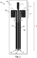
- FIG. 1 depicts a schematic diagram of an antenna 100.
- the antenna 100 is a dual band antenna that can transmit or receive signals of a first frequency and a second frequency. The first and the second frequencies reside in different frequency spectrums or bands.
- the antenna 100 includes a non-conducting surface 102.
- the non-conducting surface 102 may be a printed circuit board (PCB) or plastic or any sturdy material that does not conduct electricity.
- the antenna 100 includes a first metallic section 104 made of a conducting material such as copper and laid on the non-conducting surface 102.
- the antenna 100 also includes a second metallic section 108 made of a conducting material and located next to or alongside the first metallic section 104 and separated by a gap such that the first metallic section 104 and the second metallic section 108 do not touch each other.
- the antenna 100 further includes a third metallic section 106 located next to or alongside the second metallic section 108 and made of a conducting material.
- the first metallic section 104, the second metallic section 108 and the third metallic section 106 are elongated. There is a gap between the second metallic section 108 and the third metallic section 106 such that the second metallic section 108 does not touch the third metallic section 106.
- the first metallic section 104 is attached to an electronic circuit 118 on one end and to a metallic plate 114 alongside it at the other end.
- the metallic plate 114 is attached to the first metallic section 104 such that there is a gap 110 between the first metallic section 104 and the metallic plate 114.
- the third metallic section 106 is attached to a metallic plate 116 alongside the third metallic section 106 such that there is a gap 112 between the third metallic section 106 and the metallic plate 116 along a part of the length of the metallic plate 116.
- the length L2 of the plate 114 is substantially equal to the quarter wavelength of the first frequency. Also, the lengths of the gaps 110, 112 are slightly less than the quarter wavelength of the first frequency.
- the lengths of the gaps 110, 112 are approximately 95% to the quarter wavelength of the first frequency leaving approximately 5% length of the metallic plates 114, 116 to provide an electrical connection between the first metallic section 104 and the metallic plate 114, and also the same for the third metallic section 106 and the metallic plate 116.
- the gaps 110, 112 are provided to reduce the common mode current or radiation from sections 104, 106 and 108 so that interference from the sections 104, 106 and 108 to other antennas or devices can be reduced.
- a person skilled in the art would know that if the lengths of the gaps 110, 112 are close to the quarter wavelength of the first frequency, the antenna 100 would provide a more optimal reduction in the common mode currents.
- Another metallic plate 122 is attached to the end of the second metallic section 108 and extends the second metallic section 108, as such the length L1 is substantially equal to the length L2. That is the length L1 is equal or approximately equal to the length L2.
- An encircled portion 124 including the metallic plates 114, 116 including the upper portion of the second metallic section 108 and the metallic plate 122 form a high band antenna serving the first frequency.
- the second metallic section 108 is connected to a feeding port 120, as shown.
- the feeding port 120 is configured to be coupled with the transmitter/receiver (not shown) that may use the antenna 100 for transmitting and/or receiving signals.
- the length L3 of the second metallic section 108 and the metallic plate 122 combined may be substantially equal to the quarter wavelength of the second frequency.
- the width of the metallic plates 114, 116 may be greater than the width of the first metallic section 104 and the second metallic section 106 respectively.
- the widths of the first, second and third metallic sections 104, 108, 106 may be substantially same.
- the width of the second metallic section 108 may be wider than the first metallic section 104.
- the width of the metallic plate 122 may be smaller than the width of the metallic plate 114 or the metallic plate 116.
- the length L3 may be greater than the length L1.
- the overall length of the antenna 100 may be smaller than 15 millimeters. However, a person skilled in the art would realize that the over length of the antenna 100 may depend on the frequency bands for which the antenna 100 is designed.
- the third metallic section 106 is connected to an electronic circuit 118 on the other end.
- This electronic circuit 118 may have the same internal circuitry as the electronic circuit 118 connected to the first metallic section 104.
- the high band antenna operates as a halve wave dipole.
- a first quarter wavelength is formed by the conductive plate 122 while the second quarter wavelength is formed by conductive plates 114 and 116.
- Two gaps 110 and 112 are implemented to reduce common mode currents going down along the transmission line that is formed by the combination of the first metallic section 104, the second metallic section 108 and the third metallic section 106.
- the lengths of the gaps 110, 112 may be quarter wavelength of the first frequency.
- the low band antenna formed by the second metallic section 108 along with the metallic plate 122 operates as a quarter wave antenna for the second frequency. This is possible if the transmission line (formed by the combination of the first metallic section 104, the second metallic section 108 and the third metallic section 106) carries current in one direction only. This is accomplished by the electronic circuits 118.
- the non-conducting surface 102 may have a thickness of 1 or 1.6mm.
- the overall length and width of the non-conducting surface 102 may be 74mm by 22mm.
- the electronic circuit 118 that is connected to the first metallic section 106 may be different from the electronic circuit 118 that is connected to the third metallic section 106.
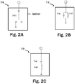
- Figures 2A-C illustrates some examples of the electronic circuit 118.
- FIG. 2A shows the electronic circuit 118 in one embodiment.
- the electronic circuit 118 includes a switch SW1.
- the switch SW1 In the first position the switch SW1 is configured to connect the first metallic section 104 or the third metallic section 106 respectively, to ground. In this configuration, the high band antenna can operate because the transmission line has currents in opposite directions.
- the switches SW1 are open and the first metallic section 104 and the third metallic section 106 are open at the bottom. It should be noted that the switch SW1 may be driven by the communication system that uses the antenna 100. In this configuration, the transmission line has currents flowing in the same direction and the overall length of the second metallic section 108 plus the metallic plate 122 is a quarter wavelength of the second frequency and the entire antenna structure functions as a monopole antenna.
- Figure 2B shows the electronic circuit 118 in another embodiment in which a capacitor Cap and an inductor Coil are coupled in parallel.
- the values of Cap and Coil may be selected to resonate at the second frequency.
- the transmission line has currents in the same direction and the overall length of the second metallic section 108 plus the metallic plate 122 is a quarter wavelength of the second frequency and the entire antenna structure functions as a monopole antenna.
- the combination of Cap and Coil is out of resonance and Cap functions as a short.
- the high band antenna can operate as the transmission line has currents in opposite directions.
- Figure 2C shows another example of the electronic circuit 118 with a series circuit of an inductor (Coil) and a capacitor (Cap).
- the values of these components are chosen to resonate at the first frequency.
- the high band antenna can operate because the transmission line has currents in opposite directions.
- the series circuit is out of resonance and poses impedance and the transmission line has currents in the same direction and the length of the transmission line together with the high band antenna structure is a quarter wavelength with respect to the low frequency band such that the structure functions as a monopole antenna.
- Figures 3 shows simulated S-parameters [dB] of the antenna 100.
- the curve shows the input reflection coefficient of feeding port 120.
- An efficient matching of the antenna to the transmitter can be established with an input reflection coefficient of -10dB or better (vertical axis).
- the higher frequency band 204 is in the frequency range 5-7 GHz while the lower frequency band 202 covers 0.7-0.9 GHz.
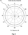
- Figure 4 shows a simulated radiation pattern [dBi] of the antenna 100 in the horizontal plane at 5.9GHz.
- the directivity of the radiation is omnidirectional with a gain of 5.22dBi.
- the antenna 100 radiates omnidirectionally, as required for applications such as C2C or C2X communication.
Landscapes
- Details Of Aerials (AREA)
Applications Claiming Priority (1)
| Application Number | Priority Date | Filing Date | Title |
|---|---|---|---|
| US15/462,625 US10381717B2 (en) | 2017-03-17 | 2017-03-17 | Automotive antenna |
Publications (2)
| Publication Number | Publication Date |
|---|---|
| EP3376594A1 true EP3376594A1 (de) | 2018-09-19 |
| EP3376594B1 EP3376594B1 (de) | 2021-06-09 |
Family
ID=61244433
Family Applications (1)
| Application Number | Title | Priority Date | Filing Date |
|---|---|---|---|
| EP18157325.4A Active EP3376594B1 (de) | 2017-03-17 | 2018-02-19 | Fahrzeugantenne |
Country Status (2)
| Country | Link |
|---|---|
| US (1) | US10381717B2 (de) |
| EP (1) | EP3376594B1 (de) |
Cited By (1)
| Publication number | Priority date | Publication date | Assignee | Title |
|---|---|---|---|---|
| US12482931B2 (en) * | 2022-08-31 | 2025-11-25 | Hyundai Mobis Co., Ltd. | Switching antenna for vehicular UWB communication |
Families Citing this family (1)
| Publication number | Priority date | Publication date | Assignee | Title |
|---|---|---|---|---|
| KR102781236B1 (ko) * | 2020-06-11 | 2025-03-12 | 동우 화인켐 주식회사 | 안테나 소자 및 이를 포함하는 디스플레이 장치 |
Citations (1)
| Publication number | Priority date | Publication date | Assignee | Title |
|---|---|---|---|---|
| US20060158383A1 (en) * | 2005-01-18 | 2006-07-20 | Samsung Electronics Co., Ltd. | Substrate type dipole antenna having stable radiation pattern |
Family Cites Families (10)
| Publication number | Priority date | Publication date | Assignee | Title |
|---|---|---|---|---|
| US4063246A (en) | 1976-06-01 | 1977-12-13 | Transco Products, Inc. | Coplanar stripline antenna |
| WO1997026685A1 (en) | 1996-01-16 | 1997-07-24 | Motorola Inc. | Shortened monopole antenna |
| US5949383A (en) * | 1997-10-20 | 1999-09-07 | Ericsson Inc. | Compact antenna structures including baluns |
| US20030048226A1 (en) | 2001-01-31 | 2003-03-13 | Tantivy Communications, Inc. | Antenna for array applications |
| TW560107B (en) * | 2002-09-24 | 2003-11-01 | Gemtek Technology Co Ltd | Antenna structure of multi-frequency printed circuit |
| US6961028B2 (en) | 2003-01-17 | 2005-11-01 | Lockheed Martin Corporation | Low profile dual frequency dipole antenna structure |
| WO2014181569A1 (ja) * | 2013-05-10 | 2014-11-13 | 株式会社村田製作所 | アンテナ装置 |
| EP2827448B1 (de) * | 2013-07-16 | 2019-04-03 | TE Connectivity Germany GmbH | Antennenelement für drahtlose Kommunikation |
| US10270170B2 (en) * | 2014-04-15 | 2019-04-23 | QuantalRF AG | Compound loop antenna system with isolation frequency agility |
| TWI599093B (zh) * | 2016-03-11 | 2017-09-11 | 宏碁股份有限公司 | 具有窄接地面淨空區之天線元件的通訊裝置 |
-
2017
- 2017-03-17 US US15/462,625 patent/US10381717B2/en active Active
-
2018
- 2018-02-19 EP EP18157325.4A patent/EP3376594B1/de active Active
Patent Citations (1)
| Publication number | Priority date | Publication date | Assignee | Title |
|---|---|---|---|---|
| US20060158383A1 (en) * | 2005-01-18 | 2006-07-20 | Samsung Electronics Co., Ltd. | Substrate type dipole antenna having stable radiation pattern |
Non-Patent Citations (2)
| Title |
|---|
| ABOUFOUL TAMER ET AL: "Multiple-parameter reconfiguration in a single planar ultra-wideband antenna for advanced wireless communication systems", IET MICROWAVES, ANTENNAS & PROPAGA, THE INSTITUTION OF ENGINEERING AND TECHNOLOGY, UNITED KINGDOM, vol. 8, no. 11, 19 August 2014 (2014-08-19), pages 849 - 857, XP006049368, ISSN: 1751-8725, DOI: 10.1049/IET-MAP.2013.0690 * |
| BHASKAR SUDHIR ET AL: "Compact planar rectangular monopole antenna for Bluetooth and UWB Applications", 2016 IEEE UTTAR PRADESH SECTION INTERNATIONAL CONFERENCE ON ELECTRICAL, COMPUTER AND ELECTRONICS ENGINEERING (UPCON), IEEE, 9 December 2016 (2016-12-09), pages 138 - 141, XP033084641, DOI: 10.1109/UPCON.2016.7894640 * |
Cited By (1)
| Publication number | Priority date | Publication date | Assignee | Title |
|---|---|---|---|---|
| US12482931B2 (en) * | 2022-08-31 | 2025-11-25 | Hyundai Mobis Co., Ltd. | Switching antenna for vehicular UWB communication |
Also Published As
| Publication number | Publication date |
|---|---|
| US10381717B2 (en) | 2019-08-13 |
| EP3376594B1 (de) | 2021-06-09 |
| US20180269566A1 (en) | 2018-09-20 |
Similar Documents
| Publication | Publication Date | Title |
|---|---|---|
| US6218992B1 (en) | Compact, broadband inverted-F antennas with conductive elements and wireless communicators incorporating same | |
| US6515625B1 (en) | Antenna | |
| US10333208B2 (en) | Antenna device | |
| US6268831B1 (en) | Inverted-f antennas with multiple planar radiating elements and wireless communicators incorporating same | |
| US6429819B1 (en) | Dual band patch bowtie slot antenna structure | |
| US7471246B2 (en) | Antenna with one or more holes | |
| JP4121424B2 (ja) | 2偏波共用アンテナ | |
| US6229487B1 (en) | Inverted-F antennas having non-linear conductive elements and wireless communicators incorporating the same | |
| US9660347B2 (en) | Printed coupled-fed multi-band antenna and electronic system | |
| US20100013730A1 (en) | Antenna arrangement | |
| CN104183906B (zh) | 车载天线 | |
| WO2010117491A2 (en) | Wideband high gain antenna | |
| CN111052506A (zh) | 天线装置 | |
| CN113078449B (zh) | 天线结构及具有该天线结构的无线通信装置 | |
| JP2009529286A (ja) | Vhf及びuhf信号受信用二重帯域アンテナ及び無線端末装置 | |
| US8665169B2 (en) | Monopole antenna | |
| JP2004088198A (ja) | モノポールアンテナ装置およびこれを用いた通信システム | |
| CN110462932A (zh) | Mimo天线模块 | |
| CN104969413B (zh) | 集成天线及其制造方法 | |
| EP3376594B1 (de) | Fahrzeugantenne | |
| US9054426B2 (en) | Radio apparatus and antenna device | |
| CN113078444A (zh) | 天线结构及具有该天线结构的无线通信装置 | |
| CN113078445A (zh) | 天线结构及具有该天线结构的无线通信装置 | |
| US6980172B2 (en) | Multi-band cable antenna | |
| JP2592128Y2 (ja) | 平型アンテナ |
Legal Events
| Date | Code | Title | Description |
|---|---|---|---|
| PUAI | Public reference made under article 153(3) epc to a published international application that has entered the european phase |
Free format text: ORIGINAL CODE: 0009012 |
|
| STAA | Information on the status of an ep patent application or granted ep patent |
Free format text: STATUS: THE APPLICATION HAS BEEN PUBLISHED |
|
| AK | Designated contracting states |
Kind code of ref document: A1 Designated state(s): AL AT BE BG CH CY CZ DE DK EE ES FI FR GB GR HR HU IE IS IT LI LT LU LV MC MK MT NL NO PL PT RO RS SE SI SK SM TR |
|
| AX | Request for extension of the european patent |
Extension state: BA ME |
|
| STAA | Information on the status of an ep patent application or granted ep patent |
Free format text: STATUS: REQUEST FOR EXAMINATION WAS MADE |
|
| 17P | Request for examination filed |
Effective date: 20190319 |
|
| RBV | Designated contracting states (corrected) |
Designated state(s): AL AT BE BG CH CY CZ DE DK EE ES FI FR GB GR HR HU IE IS IT LI LT LU LV MC MK MT NL NO PL PT RO RS SE SI SK SM TR |
|
| STAA | Information on the status of an ep patent application or granted ep patent |
Free format text: STATUS: EXAMINATION IS IN PROGRESS |
|
| 17Q | First examination report despatched |
Effective date: 20200507 |
|
| GRAP | Despatch of communication of intention to grant a patent |
Free format text: ORIGINAL CODE: EPIDOSNIGR1 |
|
| STAA | Information on the status of an ep patent application or granted ep patent |
Free format text: STATUS: GRANT OF PATENT IS INTENDED |
|
| INTG | Intention to grant announced |
Effective date: 20210114 |
|
| GRAJ | Information related to disapproval of communication of intention to grant by the applicant or resumption of examination proceedings by the epo deleted |
Free format text: ORIGINAL CODE: EPIDOSDIGR1 |
|
| STAA | Information on the status of an ep patent application or granted ep patent |
Free format text: STATUS: EXAMINATION IS IN PROGRESS |
|
| GRAP | Despatch of communication of intention to grant a patent |
Free format text: ORIGINAL CODE: EPIDOSNIGR1 |
|
| STAA | Information on the status of an ep patent application or granted ep patent |
Free format text: STATUS: GRANT OF PATENT IS INTENDED |
|
| INTC | Intention to grant announced (deleted) | ||
| GRAS | Grant fee paid |
Free format text: ORIGINAL CODE: EPIDOSNIGR3 |
|
| GRAA | (expected) grant |
Free format text: ORIGINAL CODE: 0009210 |
|
| STAA | Information on the status of an ep patent application or granted ep patent |
Free format text: STATUS: THE PATENT HAS BEEN GRANTED |
|
| INTG | Intention to grant announced |
Effective date: 20210428 |
|
| AK | Designated contracting states |
Kind code of ref document: B1 Designated state(s): AL AT BE BG CH CY CZ DE DK EE ES FI FR GB GR HR HU IE IS IT LI LT LU LV MC MK MT NL NO PL PT RO RS SE SI SK SM TR |
|
| REG | Reference to a national code |
Ref country code: GB Ref legal event code: FG4D |
|
| REG | Reference to a national code |
Ref country code: CH Ref legal event code: EP Ref country code: AT Ref legal event code: REF Ref document number: 1401240 Country of ref document: AT Kind code of ref document: T Effective date: 20210615 |
|
| REG | Reference to a national code |
Ref country code: DE Ref legal event code: R096 Ref document number: 602018018217 Country of ref document: DE |
|
| REG | Reference to a national code |
Ref country code: IE Ref legal event code: FG4D |
|
| REG | Reference to a national code |
Ref country code: LT Ref legal event code: MG9D |
|
| PG25 | Lapsed in a contracting state [announced via postgrant information from national office to epo] |
Ref country code: HR Free format text: LAPSE BECAUSE OF FAILURE TO SUBMIT A TRANSLATION OF THE DESCRIPTION OR TO PAY THE FEE WITHIN THE PRESCRIBED TIME-LIMIT Effective date: 20210609 Ref country code: BG Free format text: LAPSE BECAUSE OF FAILURE TO SUBMIT A TRANSLATION OF THE DESCRIPTION OR TO PAY THE FEE WITHIN THE PRESCRIBED TIME-LIMIT Effective date: 20210909 Ref country code: FI Free format text: LAPSE BECAUSE OF FAILURE TO SUBMIT A TRANSLATION OF THE DESCRIPTION OR TO PAY THE FEE WITHIN THE PRESCRIBED TIME-LIMIT Effective date: 20210609 Ref country code: LT Free format text: LAPSE BECAUSE OF FAILURE TO SUBMIT A TRANSLATION OF THE DESCRIPTION OR TO PAY THE FEE WITHIN THE PRESCRIBED TIME-LIMIT Effective date: 20210609 |
|
| REG | Reference to a national code |
Ref country code: AT Ref legal event code: MK05 Ref document number: 1401240 Country of ref document: AT Kind code of ref document: T Effective date: 20210609 |
|
| REG | Reference to a national code |
Ref country code: NL Ref legal event code: MP Effective date: 20210609 |
|
| PG25 | Lapsed in a contracting state [announced via postgrant information from national office to epo] |
Ref country code: RS Free format text: LAPSE BECAUSE OF FAILURE TO SUBMIT A TRANSLATION OF THE DESCRIPTION OR TO PAY THE FEE WITHIN THE PRESCRIBED TIME-LIMIT Effective date: 20210609 Ref country code: SE Free format text: LAPSE BECAUSE OF FAILURE TO SUBMIT A TRANSLATION OF THE DESCRIPTION OR TO PAY THE FEE WITHIN THE PRESCRIBED TIME-LIMIT Effective date: 20210609 Ref country code: LV Free format text: LAPSE BECAUSE OF FAILURE TO SUBMIT A TRANSLATION OF THE DESCRIPTION OR TO PAY THE FEE WITHIN THE PRESCRIBED TIME-LIMIT Effective date: 20210609 Ref country code: NO Free format text: LAPSE BECAUSE OF FAILURE TO SUBMIT A TRANSLATION OF THE DESCRIPTION OR TO PAY THE FEE WITHIN THE PRESCRIBED TIME-LIMIT Effective date: 20210909 Ref country code: GR Free format text: LAPSE BECAUSE OF FAILURE TO SUBMIT A TRANSLATION OF THE DESCRIPTION OR TO PAY THE FEE WITHIN THE PRESCRIBED TIME-LIMIT Effective date: 20210910 |
|
| PG25 | Lapsed in a contracting state [announced via postgrant information from national office to epo] |
Ref country code: AT Free format text: LAPSE BECAUSE OF FAILURE TO SUBMIT A TRANSLATION OF THE DESCRIPTION OR TO PAY THE FEE WITHIN THE PRESCRIBED TIME-LIMIT Effective date: 20210609 Ref country code: CZ Free format text: LAPSE BECAUSE OF FAILURE TO SUBMIT A TRANSLATION OF THE DESCRIPTION OR TO PAY THE FEE WITHIN THE PRESCRIBED TIME-LIMIT Effective date: 20210609 Ref country code: RO Free format text: LAPSE BECAUSE OF FAILURE TO SUBMIT A TRANSLATION OF THE DESCRIPTION OR TO PAY THE FEE WITHIN THE PRESCRIBED TIME-LIMIT Effective date: 20210609 Ref country code: PT Free format text: LAPSE BECAUSE OF FAILURE TO SUBMIT A TRANSLATION OF THE DESCRIPTION OR TO PAY THE FEE WITHIN THE PRESCRIBED TIME-LIMIT Effective date: 20211011 Ref country code: NL Free format text: LAPSE BECAUSE OF FAILURE TO SUBMIT A TRANSLATION OF THE DESCRIPTION OR TO PAY THE FEE WITHIN THE PRESCRIBED TIME-LIMIT Effective date: 20210609 Ref country code: SK Free format text: LAPSE BECAUSE OF FAILURE TO SUBMIT A TRANSLATION OF THE DESCRIPTION OR TO PAY THE FEE WITHIN THE PRESCRIBED TIME-LIMIT Effective date: 20210609 Ref country code: SM Free format text: LAPSE BECAUSE OF FAILURE TO SUBMIT A TRANSLATION OF THE DESCRIPTION OR TO PAY THE FEE WITHIN THE PRESCRIBED TIME-LIMIT Effective date: 20210609 Ref country code: EE Free format text: LAPSE BECAUSE OF FAILURE TO SUBMIT A TRANSLATION OF THE DESCRIPTION OR TO PAY THE FEE WITHIN THE PRESCRIBED TIME-LIMIT Effective date: 20210609 Ref country code: ES Free format text: LAPSE BECAUSE OF FAILURE TO SUBMIT A TRANSLATION OF THE DESCRIPTION OR TO PAY THE FEE WITHIN THE PRESCRIBED TIME-LIMIT Effective date: 20210609 |
|
| PG25 | Lapsed in a contracting state [announced via postgrant information from national office to epo] |
Ref country code: PL Free format text: LAPSE BECAUSE OF FAILURE TO SUBMIT A TRANSLATION OF THE DESCRIPTION OR TO PAY THE FEE WITHIN THE PRESCRIBED TIME-LIMIT Effective date: 20210609 |
|
| REG | Reference to a national code |
Ref country code: DE Ref legal event code: R097 Ref document number: 602018018217 Country of ref document: DE |
|
| PLBE | No opposition filed within time limit |
Free format text: ORIGINAL CODE: 0009261 |
|
| STAA | Information on the status of an ep patent application or granted ep patent |
Free format text: STATUS: NO OPPOSITION FILED WITHIN TIME LIMIT |
|
| PG25 | Lapsed in a contracting state [announced via postgrant information from national office to epo] |
Ref country code: DK Free format text: LAPSE BECAUSE OF FAILURE TO SUBMIT A TRANSLATION OF THE DESCRIPTION OR TO PAY THE FEE WITHIN THE PRESCRIBED TIME-LIMIT Effective date: 20210609 |
|
| 26N | No opposition filed |
Effective date: 20220310 |
|
| PG25 | Lapsed in a contracting state [announced via postgrant information from national office to epo] |
Ref country code: AL Free format text: LAPSE BECAUSE OF FAILURE TO SUBMIT A TRANSLATION OF THE DESCRIPTION OR TO PAY THE FEE WITHIN THE PRESCRIBED TIME-LIMIT Effective date: 20210609 |
|
| PG25 | Lapsed in a contracting state [announced via postgrant information from national office to epo] |
Ref country code: IT Free format text: LAPSE BECAUSE OF FAILURE TO SUBMIT A TRANSLATION OF THE DESCRIPTION OR TO PAY THE FEE WITHIN THE PRESCRIBED TIME-LIMIT Effective date: 20210609 |
|
| PG25 | Lapsed in a contracting state [announced via postgrant information from national office to epo] |
Ref country code: MC Free format text: LAPSE BECAUSE OF FAILURE TO SUBMIT A TRANSLATION OF THE DESCRIPTION OR TO PAY THE FEE WITHIN THE PRESCRIBED TIME-LIMIT Effective date: 20210609 |
|
| REG | Reference to a national code |
Ref country code: CH Ref legal event code: PL |
|
| REG | Reference to a national code |
Ref country code: BE Ref legal event code: MM Effective date: 20220228 |
|
| GBPC | Gb: european patent ceased through non-payment of renewal fee |
Effective date: 20220219 |
|
| PG25 | Lapsed in a contracting state [announced via postgrant information from national office to epo] |
Ref country code: LU Free format text: LAPSE BECAUSE OF NON-PAYMENT OF DUE FEES Effective date: 20220219 |
|
| PG25 | Lapsed in a contracting state [announced via postgrant information from national office to epo] |
Ref country code: LI Free format text: LAPSE BECAUSE OF NON-PAYMENT OF DUE FEES Effective date: 20220228 Ref country code: IE Free format text: LAPSE BECAUSE OF NON-PAYMENT OF DUE FEES Effective date: 20220219 Ref country code: GB Free format text: LAPSE BECAUSE OF NON-PAYMENT OF DUE FEES Effective date: 20220219 Ref country code: CH Free format text: LAPSE BECAUSE OF NON-PAYMENT OF DUE FEES Effective date: 20220228 |
|
| PG25 | Lapsed in a contracting state [announced via postgrant information from national office to epo] |
Ref country code: BE Free format text: LAPSE BECAUSE OF NON-PAYMENT OF DUE FEES Effective date: 20220228 |
|
| P01 | Opt-out of the competence of the unified patent court (upc) registered |
Effective date: 20230725 |
|
| PG25 | Lapsed in a contracting state [announced via postgrant information from national office to epo] |
Ref country code: HU Free format text: LAPSE BECAUSE OF FAILURE TO SUBMIT A TRANSLATION OF THE DESCRIPTION OR TO PAY THE FEE WITHIN THE PRESCRIBED TIME-LIMIT; INVALID AB INITIO Effective date: 20180219 |
|
| PG25 | Lapsed in a contracting state [announced via postgrant information from national office to epo] |
Ref country code: MK Free format text: LAPSE BECAUSE OF FAILURE TO SUBMIT A TRANSLATION OF THE DESCRIPTION OR TO PAY THE FEE WITHIN THE PRESCRIBED TIME-LIMIT Effective date: 20210609 Ref country code: CY Free format text: LAPSE BECAUSE OF FAILURE TO SUBMIT A TRANSLATION OF THE DESCRIPTION OR TO PAY THE FEE WITHIN THE PRESCRIBED TIME-LIMIT Effective date: 20210609 |
|
| PG25 | Lapsed in a contracting state [announced via postgrant information from national office to epo] |
Ref country code: MT Free format text: LAPSE BECAUSE OF FAILURE TO SUBMIT A TRANSLATION OF THE DESCRIPTION OR TO PAY THE FEE WITHIN THE PRESCRIBED TIME-LIMIT Effective date: 20210609 |
|
| PG25 | Lapsed in a contracting state [announced via postgrant information from national office to epo] |
Ref country code: TR Free format text: LAPSE BECAUSE OF FAILURE TO SUBMIT A TRANSLATION OF THE DESCRIPTION OR TO PAY THE FEE WITHIN THE PRESCRIBED TIME-LIMIT Effective date: 20210609 |
|
| PGFP | Annual fee paid to national office [announced via postgrant information from national office to epo] |
Ref country code: DE Payment date: 20260121 Year of fee payment: 9 |
|
| PGFP | Annual fee paid to national office [announced via postgrant information from national office to epo] |
Ref country code: FR Payment date: 20260121 Year of fee payment: 9 |