EP3376583A1 - Sekundärbatterie, batteriepack und fahrzeug - Google Patents
Sekundärbatterie, batteriepack und fahrzeug Download PDFInfo
- Publication number
- EP3376583A1 EP3376583A1 EP18156915.3A EP18156915A EP3376583A1 EP 3376583 A1 EP3376583 A1 EP 3376583A1 EP 18156915 A EP18156915 A EP 18156915A EP 3376583 A1 EP3376583 A1 EP 3376583A1
- Authority
- EP
- European Patent Office
- Prior art keywords
- electrolytic solution
- negative electrode
- secondary battery
- battery
- positive electrode
- Prior art date
- Legal status (The legal status is an assumption and is not a legal conclusion. Google has not performed a legal analysis and makes no representation as to the accuracy of the status listed.)
- Withdrawn
Links
- 239000008151 electrolyte solution Substances 0.000 claims abstract description 94
- 239000003960 organic solvent Substances 0.000 claims abstract description 36
- XLYOFNOQVPJJNP-UHFFFAOYSA-N water Substances O XLYOFNOQVPJJNP-UHFFFAOYSA-N 0.000 claims abstract description 36
- 150000003839 salts Chemical class 0.000 claims abstract description 20
- 239000003792 electrolyte Substances 0.000 claims abstract description 18
- OKKJLVBELUTLKV-UHFFFAOYSA-N Methanol Chemical compound OC OKKJLVBELUTLKV-UHFFFAOYSA-N 0.000 claims description 45
- GWEVSGVZZGPLCZ-UHFFFAOYSA-N Titan oxide Chemical compound O=[Ti]=O GWEVSGVZZGPLCZ-UHFFFAOYSA-N 0.000 claims description 23
- WEVYAHXRMPXWCK-UHFFFAOYSA-N Acetonitrile Chemical compound CC#N WEVYAHXRMPXWCK-UHFFFAOYSA-N 0.000 claims description 18
- IAZDPXIOMUYVGZ-UHFFFAOYSA-N Dimethylsulphoxide Chemical compound CS(C)=O IAZDPXIOMUYVGZ-UHFFFAOYSA-N 0.000 claims description 17
- KFZMGEQAYNKOFK-UHFFFAOYSA-N Isopropanol Chemical compound CC(C)O KFZMGEQAYNKOFK-UHFFFAOYSA-N 0.000 claims description 17
- 239000011149 active material Substances 0.000 claims description 17
- OGIDPMRJRNCKJF-UHFFFAOYSA-N titanium oxide Inorganic materials [Ti]=O OGIDPMRJRNCKJF-UHFFFAOYSA-N 0.000 claims description 11
- INHCSSUBVCNVSK-UHFFFAOYSA-L lithium sulfate Chemical compound [Li+].[Li+].[O-]S([O-])(=O)=O INHCSSUBVCNVSK-UHFFFAOYSA-L 0.000 claims description 10
- FDLZQPXZHIFURF-UHFFFAOYSA-N [O-2].[Ti+4].[Li+] Chemical compound [O-2].[Ti+4].[Li+] FDLZQPXZHIFURF-UHFFFAOYSA-N 0.000 claims description 8
- 229910003002 lithium salt Inorganic materials 0.000 claims description 7
- 159000000002 lithium salts Chemical group 0.000 claims description 7
- 230000001172 regenerating effect Effects 0.000 claims description 7
- WMFOQBRAJBCJND-UHFFFAOYSA-M Lithium hydroxide Chemical compound [Li+].[OH-] WMFOQBRAJBCJND-UHFFFAOYSA-M 0.000 claims description 6
- 239000002861 polymer material Substances 0.000 claims description 4
- 229910032387 LiCoO2 Inorganic materials 0.000 claims description 3
- 150000001298 alcohols Chemical class 0.000 claims description 3
- 239000002798 polar solvent Substances 0.000 claims description 3
- 229910052493 LiFePO4 Inorganic materials 0.000 claims 1
- 229910002097 Lithium manganese(III,IV) oxide Inorganic materials 0.000 claims 1
- 239000007773 negative electrode material Substances 0.000 description 38
- 239000007774 positive electrode material Substances 0.000 description 33
- -1 chrome ion Chemical class 0.000 description 28
- 239000006258 conductive agent Substances 0.000 description 28
- 239000011230 binding agent Substances 0.000 description 25
- 210000004027 cell Anatomy 0.000 description 21
- 239000002245 particle Substances 0.000 description 20
- 239000002131 composite material Substances 0.000 description 18
- 229910002986 Li4Ti5O12 Inorganic materials 0.000 description 16
- 229910052751 metal Inorganic materials 0.000 description 16
- 239000002184 metal Substances 0.000 description 16
- 229910002102 lithium manganese oxide Inorganic materials 0.000 description 14
- VLXXBCXTUVRROQ-UHFFFAOYSA-N lithium;oxido-oxo-(oxomanganiooxy)manganese Chemical compound [Li+].[O-][Mn](=O)O[Mn]=O VLXXBCXTUVRROQ-UHFFFAOYSA-N 0.000 description 14
- 238000007789 sealing Methods 0.000 description 13
- 239000002904 solvent Substances 0.000 description 13
- 239000010936 titanium Substances 0.000 description 13
- 230000000052 comparative effect Effects 0.000 description 12
- 239000011888 foil Substances 0.000 description 12
- 238000002156 mixing Methods 0.000 description 12
- 239000011164 primary particle Substances 0.000 description 12
- 239000003125 aqueous solvent Substances 0.000 description 11
- 229910001416 lithium ion Inorganic materials 0.000 description 11
- 239000011163 secondary particle Substances 0.000 description 11
- 239000002002 slurry Substances 0.000 description 11
- PXHVJJICTQNCMI-UHFFFAOYSA-N Nickel Chemical compound [Ni] PXHVJJICTQNCMI-UHFFFAOYSA-N 0.000 description 10
- 229910052744 lithium Inorganic materials 0.000 description 10
- WHXSMMKQMYFTQS-UHFFFAOYSA-N Lithium Chemical compound [Li] WHXSMMKQMYFTQS-UHFFFAOYSA-N 0.000 description 9
- ZMXDDKWLCZADIW-UHFFFAOYSA-N N,N-Dimethylformamide Chemical compound CN(C)C=O ZMXDDKWLCZADIW-UHFFFAOYSA-N 0.000 description 9
- 238000004891 communication Methods 0.000 description 9
- 238000004519 manufacturing process Methods 0.000 description 9
- 230000003247 decreasing effect Effects 0.000 description 8
- 238000003860 storage Methods 0.000 description 8
- LYCAIKOWRPUZTN-UHFFFAOYSA-N Ethylene glycol Chemical compound OCCO LYCAIKOWRPUZTN-UHFFFAOYSA-N 0.000 description 7
- UFHFLCQGNIYNRP-UHFFFAOYSA-N Hydrogen Chemical compound [H][H] UFHFLCQGNIYNRP-UHFFFAOYSA-N 0.000 description 7
- 238000005868 electrolysis reaction Methods 0.000 description 7
- XEEYBQQBJWHFJM-UHFFFAOYSA-N iron Substances [Fe] XEEYBQQBJWHFJM-UHFFFAOYSA-N 0.000 description 7
- 238000000034 method Methods 0.000 description 7
- 239000000203 mixture Substances 0.000 description 7
- 229910052596 spinel Inorganic materials 0.000 description 7
- 239000011029 spinel Substances 0.000 description 7
- OKTJSMMVPCPJKN-UHFFFAOYSA-N Carbon Chemical compound [C] OKTJSMMVPCPJKN-UHFFFAOYSA-N 0.000 description 6
- 239000002033 PVDF binder Substances 0.000 description 6
- 239000004698 Polyethylene Substances 0.000 description 6
- 239000004743 Polypropylene Substances 0.000 description 6
- WYURNTSHIVDZCO-UHFFFAOYSA-N Tetrahydrofuran Chemical compound C1CCOC1 WYURNTSHIVDZCO-UHFFFAOYSA-N 0.000 description 6
- 238000001514 detection method Methods 0.000 description 6
- 238000010586 diagram Methods 0.000 description 6
- 239000001257 hydrogen Substances 0.000 description 6
- 229910052739 hydrogen Inorganic materials 0.000 description 6
- KWGKDLIKAYFUFQ-UHFFFAOYSA-M lithium chloride Chemical compound [Li+].[Cl-] KWGKDLIKAYFUFQ-UHFFFAOYSA-M 0.000 description 6
- 229920000573 polyethylene Polymers 0.000 description 6
- 229920001155 polypropylene Polymers 0.000 description 6
- 229920002981 polyvinylidene fluoride Polymers 0.000 description 6
- 229920005989 resin Polymers 0.000 description 6
- 239000011347 resin Substances 0.000 description 6
- LFQSCWFLJHTTHZ-UHFFFAOYSA-N Ethanol Chemical compound CCO LFQSCWFLJHTTHZ-UHFFFAOYSA-N 0.000 description 5
- SECXISVLQFMRJM-UHFFFAOYSA-N N-Methylpyrrolidone Chemical compound CN1CCCC1=O SECXISVLQFMRJM-UHFFFAOYSA-N 0.000 description 5
- 229910052782 aluminium Inorganic materials 0.000 description 5
- 229910052742 iron Inorganic materials 0.000 description 5
- 239000007788 liquid Substances 0.000 description 5
- 239000004745 nonwoven fabric Substances 0.000 description 5
- 239000010450 olivine Substances 0.000 description 5
- 229910052609 olivine Inorganic materials 0.000 description 5
- 239000010935 stainless steel Substances 0.000 description 5
- 229910001220 stainless steel Inorganic materials 0.000 description 5
- 229910052719 titanium Inorganic materials 0.000 description 5
- 229910000838 Al alloy Inorganic materials 0.000 description 4
- RTAQQCXQSZGOHL-UHFFFAOYSA-N Titanium Chemical compound [Ti] RTAQQCXQSZGOHL-UHFFFAOYSA-N 0.000 description 4
- 238000000354 decomposition reaction Methods 0.000 description 4
- 239000000835 fiber Substances 0.000 description 4
- 230000006870 function Effects 0.000 description 4
- 239000007789 gas Substances 0.000 description 4
- 238000002347 injection Methods 0.000 description 4
- 239000007924 injection Substances 0.000 description 4
- 150000002500 ions Chemical class 0.000 description 4
- 239000011572 manganese Substances 0.000 description 4
- 229910052759 nickel Inorganic materials 0.000 description 4
- 239000004810 polytetrafluoroethylene Substances 0.000 description 4
- 229920001343 polytetrafluoroethylene Polymers 0.000 description 4
- 238000003825 pressing Methods 0.000 description 4
- ZWEHNKRNPOVVGH-UHFFFAOYSA-N 2-Butanone Chemical compound CCC(C)=O ZWEHNKRNPOVVGH-UHFFFAOYSA-N 0.000 description 3
- CSCPPACGZOOCGX-UHFFFAOYSA-N Acetone Chemical compound CC(C)=O CSCPPACGZOOCGX-UHFFFAOYSA-N 0.000 description 3
- WVDDGKGOMKODPV-UHFFFAOYSA-N Benzyl alcohol Chemical compound OCC1=CC=CC=C1 WVDDGKGOMKODPV-UHFFFAOYSA-N 0.000 description 3
- 229920003043 Cellulose fiber Polymers 0.000 description 3
- XEKOWRVHYACXOJ-UHFFFAOYSA-N Ethyl acetate Chemical compound CCOC(C)=O XEKOWRVHYACXOJ-UHFFFAOYSA-N 0.000 description 3
- HBBGRARXTFLTSG-UHFFFAOYSA-N Lithium ion Chemical compound [Li+] HBBGRARXTFLTSG-UHFFFAOYSA-N 0.000 description 3
- DNIAPMSPPWPWGF-UHFFFAOYSA-N Propylene glycol Chemical compound CC(O)CO DNIAPMSPPWPWGF-UHFFFAOYSA-N 0.000 description 3
- ZMANZCXQSJIPKH-UHFFFAOYSA-N Triethylamine Chemical compound CCN(CC)CC ZMANZCXQSJIPKH-UHFFFAOYSA-N 0.000 description 3
- KLARSDUHONHPRF-UHFFFAOYSA-N [Li].[Mn] Chemical compound [Li].[Mn] KLARSDUHONHPRF-UHFFFAOYSA-N 0.000 description 3
- OBOYOXRQUWVUFU-UHFFFAOYSA-N [O-2].[Ti+4].[Nb+5] Chemical compound [O-2].[Ti+4].[Nb+5] OBOYOXRQUWVUFU-UHFFFAOYSA-N 0.000 description 3
- KICMAFOENQWRKZ-UHFFFAOYSA-N [O-2].[Ti+4].[Nb+5].[Na+].[O-2].[O-2].[O-2].[O-2] Chemical compound [O-2].[Ti+4].[Nb+5].[Na+].[O-2].[O-2].[O-2].[O-2] KICMAFOENQWRKZ-UHFFFAOYSA-N 0.000 description 3
- 230000009471 action Effects 0.000 description 3
- XAGFODPZIPBFFR-UHFFFAOYSA-N aluminium Chemical compound [Al] XAGFODPZIPBFFR-UHFFFAOYSA-N 0.000 description 3
- 239000003575 carbonaceous material Substances 0.000 description 3
- CKFRRHLHAJZIIN-UHFFFAOYSA-N cobalt lithium Chemical compound [Li].[Co] CKFRRHLHAJZIIN-UHFFFAOYSA-N 0.000 description 3
- 150000001875 compounds Chemical class 0.000 description 3
- 238000005260 corrosion Methods 0.000 description 3
- 230000007797 corrosion Effects 0.000 description 3
- 239000013078 crystal Substances 0.000 description 3
- MTHSVFCYNBDYFN-UHFFFAOYSA-N diethylene glycol Chemical compound OCCOCCO MTHSVFCYNBDYFN-UHFFFAOYSA-N 0.000 description 3
- 230000000694 effects Effects 0.000 description 3
- 229910001386 lithium phosphate Inorganic materials 0.000 description 3
- 229910052748 manganese Inorganic materials 0.000 description 3
- 229920002239 polyacrylonitrile Polymers 0.000 description 3
- 239000002243 precursor Substances 0.000 description 3
- 230000000284 resting effect Effects 0.000 description 3
- YLQBMQCUIZJEEH-UHFFFAOYSA-N tetrahydrofuran Natural products C=1C=COC=1 YLQBMQCUIZJEEH-UHFFFAOYSA-N 0.000 description 3
- PUPZLCDOIYMWBV-UHFFFAOYSA-N (+/-)-1,3-Butanediol Chemical compound CC(O)CCO PUPZLCDOIYMWBV-UHFFFAOYSA-N 0.000 description 2
- YEJRWHAVMIAJKC-UHFFFAOYSA-N 4-Butyrolactone Chemical compound O=C1CCCO1 YEJRWHAVMIAJKC-UHFFFAOYSA-N 0.000 description 2
- DKPFZGUDAPQIHT-UHFFFAOYSA-N Butyl acetate Natural products CCCCOC(C)=O DKPFZGUDAPQIHT-UHFFFAOYSA-N 0.000 description 2
- 229920002134 Carboxymethyl cellulose Polymers 0.000 description 2
- ROSDSFDQCJNGOL-UHFFFAOYSA-N Dimethylamine Chemical compound CNC ROSDSFDQCJNGOL-UHFFFAOYSA-N 0.000 description 2
- QUSNBJAOOMFDIB-UHFFFAOYSA-N Ethylamine Chemical compound CCN QUSNBJAOOMFDIB-UHFFFAOYSA-N 0.000 description 2
- 229910010500 Li2.9PO3.3N0.46 Inorganic materials 0.000 description 2
- 229910002984 Li7La3Zr2O12 Inorganic materials 0.000 description 2
- 229910001246 LixFePO4 Inorganic materials 0.000 description 2
- 229910014715 LixTiO2 Inorganic materials 0.000 description 2
- BZLVMXJERCGZMT-UHFFFAOYSA-N Methyl tert-butyl ether Chemical compound COC(C)(C)C BZLVMXJERCGZMT-UHFFFAOYSA-N 0.000 description 2
- BAVYZALUXZFZLV-UHFFFAOYSA-N Methylamine Chemical compound NC BAVYZALUXZFZLV-UHFFFAOYSA-N 0.000 description 2
- JGFZNNIVVJXRND-UHFFFAOYSA-N N,N-Diisopropylethylamine (DIPEA) Chemical compound CCN(C(C)C)C(C)C JGFZNNIVVJXRND-UHFFFAOYSA-N 0.000 description 2
- LRHPLDYGYMQRHN-UHFFFAOYSA-N N-Butanol Chemical compound CCCCO LRHPLDYGYMQRHN-UHFFFAOYSA-N 0.000 description 2
- 229910003260 Nb2TiO7 Inorganic materials 0.000 description 2
- 229920003171 Poly (ethylene oxide) Polymers 0.000 description 2
- XBDQKXXYIPTUBI-UHFFFAOYSA-M Propionate Chemical compound CCC([O-])=O XBDQKXXYIPTUBI-UHFFFAOYSA-M 0.000 description 2
- LMFMZUUUIFGRHQ-UHFFFAOYSA-K S(=O)(=O)([O-])F.[Fe+2].[Li+].S(=O)(=O)([O-])F.S(=O)(=O)([O-])F Chemical compound S(=O)(=O)([O-])F.[Fe+2].[Li+].S(=O)(=O)([O-])F.S(=O)(=O)([O-])F LMFMZUUUIFGRHQ-UHFFFAOYSA-K 0.000 description 2
- DKGAVHZHDRPRBM-UHFFFAOYSA-N Tert-Butanol Chemical compound CC(C)(C)O DKGAVHZHDRPRBM-UHFFFAOYSA-N 0.000 description 2
- NXPZICSHDHGMGT-UHFFFAOYSA-N [Co].[Mn].[Li] Chemical compound [Co].[Mn].[Li] NXPZICSHDHGMGT-UHFFFAOYSA-N 0.000 description 2
- SOXUFMZTHZXOGC-UHFFFAOYSA-N [Li].[Mn].[Co].[Ni] Chemical compound [Li].[Mn].[Co].[Ni] SOXUFMZTHZXOGC-UHFFFAOYSA-N 0.000 description 2
- ZYXUQEDFWHDILZ-UHFFFAOYSA-N [Ni].[Mn].[Li] Chemical compound [Ni].[Mn].[Li] ZYXUQEDFWHDILZ-UHFFFAOYSA-N 0.000 description 2
- KXKVLQRXCPHEJC-UHFFFAOYSA-N acetic acid trimethyl ester Natural products COC(C)=O KXKVLQRXCPHEJC-UHFFFAOYSA-N 0.000 description 2
- 239000006230 acetylene black Substances 0.000 description 2
- 230000000996 additive effect Effects 0.000 description 2
- 239000002390 adhesive tape Substances 0.000 description 2
- 230000002776 aggregation Effects 0.000 description 2
- 238000004220 aggregation Methods 0.000 description 2
- WERYXYBDKMZEQL-UHFFFAOYSA-N butane-1,4-diol Chemical compound OCCCCO WERYXYBDKMZEQL-UHFFFAOYSA-N 0.000 description 2
- 239000001768 carboxy methyl cellulose Substances 0.000 description 2
- 239000000571 coke Substances 0.000 description 2
- 239000000470 constituent Substances 0.000 description 2
- 229910052802 copper Inorganic materials 0.000 description 2
- 239000010949 copper Substances 0.000 description 2
- SWXVUIWOUIDPGS-UHFFFAOYSA-N diacetone alcohol Chemical compound CC(=O)CC(C)(C)O SWXVUIWOUIDPGS-UHFFFAOYSA-N 0.000 description 2
- XXJWXESWEXIICW-UHFFFAOYSA-N diethylene glycol monoethyl ether Chemical compound CCOCCOCCO XXJWXESWEXIICW-UHFFFAOYSA-N 0.000 description 2
- LZCLXQDLBQLTDK-UHFFFAOYSA-N ethyl 2-hydroxypropanoate Chemical compound CCOC(=O)C(C)O LZCLXQDLBQLTDK-UHFFFAOYSA-N 0.000 description 2
- JBTWLSYIZRCDFO-UHFFFAOYSA-N ethyl methyl carbonate Chemical compound CCOC(=O)OC JBTWLSYIZRCDFO-UHFFFAOYSA-N 0.000 description 2
- 238000011156 evaluation Methods 0.000 description 2
- 229920001973 fluoroelastomer Polymers 0.000 description 2
- JBFHTYHTHYHCDJ-UHFFFAOYSA-N gamma-caprolactone Chemical compound CCC1CCC(=O)O1 JBFHTYHTHYHCDJ-UHFFFAOYSA-N 0.000 description 2
- GAEKPEKOJKCEMS-UHFFFAOYSA-N gamma-valerolactone Chemical compound CC1CCC(=O)O1 GAEKPEKOJKCEMS-UHFFFAOYSA-N 0.000 description 2
- 238000002290 gas chromatography-mass spectrometry Methods 0.000 description 2
- 239000010439 graphite Substances 0.000 description 2
- 229910002804 graphite Inorganic materials 0.000 description 2
- 125000005842 heteroatom Chemical group 0.000 description 2
- FUZZWVXGSFPDMH-UHFFFAOYSA-M hexanoate Chemical compound CCCCCC([O-])=O FUZZWVXGSFPDMH-UHFFFAOYSA-M 0.000 description 2
- 238000009616 inductively coupled plasma Methods 0.000 description 2
- ZXEKIIBDNHEJCQ-UHFFFAOYSA-N isobutanol Chemical compound CC(C)CO ZXEKIIBDNHEJCQ-UHFFFAOYSA-N 0.000 description 2
- 239000003273 ketjen black Substances 0.000 description 2
- AMXOYNBUYSYVKV-UHFFFAOYSA-M lithium bromide Chemical compound [Li+].[Br-] AMXOYNBUYSYVKV-UHFFFAOYSA-M 0.000 description 2
- IIPYXGDZVMZOAP-UHFFFAOYSA-N lithium nitrate Chemical compound [Li+].[O-][N+]([O-])=O IIPYXGDZVMZOAP-UHFFFAOYSA-N 0.000 description 2
- 238000012423 maintenance Methods 0.000 description 2
- 239000000463 material Substances 0.000 description 2
- 230000007246 mechanism Effects 0.000 description 2
- 239000012046 mixed solvent Substances 0.000 description 2
- 229910052750 molybdenum Inorganic materials 0.000 description 2
- 239000011255 nonaqueous electrolyte Substances 0.000 description 2
- 230000003647 oxidation Effects 0.000 description 2
- 238000007254 oxidation reaction Methods 0.000 description 2
- 239000008188 pellet Substances 0.000 description 2
- 229920000139 polyethylene terephthalate Polymers 0.000 description 2
- 239000005020 polyethylene terephthalate Substances 0.000 description 2
- 229920000098 polyolefin Polymers 0.000 description 2
- 230000008569 process Effects 0.000 description 2
- HNJBEVLQSNELDL-UHFFFAOYSA-N pyrrolidin-2-one Chemical compound O=C1CCCN1 HNJBEVLQSNELDL-UHFFFAOYSA-N 0.000 description 2
- 230000009467 reduction Effects 0.000 description 2
- 239000011734 sodium Substances 0.000 description 2
- 239000007784 solid electrolyte Substances 0.000 description 2
- 229910052715 tantalum Inorganic materials 0.000 description 2
- GETQZCLCWQTVFV-UHFFFAOYSA-N trimethylamine Chemical compound CN(C)C GETQZCLCWQTVFV-UHFFFAOYSA-N 0.000 description 2
- 229910052720 vanadium Inorganic materials 0.000 description 2
- NMRPBPVERJPACX-UHFFFAOYSA-N (3S)-octan-3-ol Natural products CCCCCC(O)CC NMRPBPVERJPACX-UHFFFAOYSA-N 0.000 description 1
- LZDKZFUFMNSQCJ-UHFFFAOYSA-N 1,2-diethoxyethane Chemical compound CCOCCOCC LZDKZFUFMNSQCJ-UHFFFAOYSA-N 0.000 description 1
- RYHBNJHYFVUHQT-UHFFFAOYSA-N 1,4-Dioxane Chemical compound C1COCCO1 RYHBNJHYFVUHQT-UHFFFAOYSA-N 0.000 description 1
- GEWWCWZGHNIUBW-UHFFFAOYSA-N 1-(4-nitrophenyl)propan-2-one Chemical compound CC(=O)CC1=CC=C([N+]([O-])=O)C=C1 GEWWCWZGHNIUBW-UHFFFAOYSA-N 0.000 description 1
- KZVBBTZJMSWGTK-UHFFFAOYSA-N 1-[2-(2-butoxyethoxy)ethoxy]butane Chemical compound CCCCOCCOCCOCCCC KZVBBTZJMSWGTK-UHFFFAOYSA-N 0.000 description 1
- RWNUSVWFHDHRCJ-UHFFFAOYSA-N 1-butoxypropan-2-ol Chemical compound CCCCOCC(C)O RWNUSVWFHDHRCJ-UHFFFAOYSA-N 0.000 description 1
- RRQYJINTUHWNHW-UHFFFAOYSA-N 1-ethoxy-2-(2-ethoxyethoxy)ethane Chemical compound CCOCCOCCOCC RRQYJINTUHWNHW-UHFFFAOYSA-N 0.000 description 1
- ARXJGSRGQADJSQ-UHFFFAOYSA-N 1-methoxypropan-2-ol Chemical compound COCC(C)O ARXJGSRGQADJSQ-UHFFFAOYSA-N 0.000 description 1
- DOVZUKKPYKRVIK-UHFFFAOYSA-N 1-methoxypropan-2-yl propanoate Chemical compound CCC(=O)OC(C)COC DOVZUKKPYKRVIK-UHFFFAOYSA-N 0.000 description 1
- OAYXUHPQHDHDDZ-UHFFFAOYSA-N 2-(2-butoxyethoxy)ethanol Chemical compound CCCCOCCOCCO OAYXUHPQHDHDDZ-UHFFFAOYSA-N 0.000 description 1
- VXQBJTKSVGFQOL-UHFFFAOYSA-N 2-(2-butoxyethoxy)ethyl acetate Chemical compound CCCCOCCOCCOC(C)=O VXQBJTKSVGFQOL-UHFFFAOYSA-N 0.000 description 1
- SBASXUCJHJRPEV-UHFFFAOYSA-N 2-(2-methoxyethoxy)ethanol Chemical compound COCCOCCO SBASXUCJHJRPEV-UHFFFAOYSA-N 0.000 description 1
- CUDYYMUUJHLCGZ-UHFFFAOYSA-N 2-(2-methoxypropoxy)propan-1-ol Chemical compound COC(C)COC(C)CO CUDYYMUUJHLCGZ-UHFFFAOYSA-N 0.000 description 1
- WOFPPJOZXUTRAU-UHFFFAOYSA-N 2-Ethyl-1-hexanol Natural products CCCCC(O)CCC WOFPPJOZXUTRAU-UHFFFAOYSA-N 0.000 description 1
- XNWFRZJHXBZDAG-UHFFFAOYSA-N 2-METHOXYETHANOL Chemical compound COCCO XNWFRZJHXBZDAG-UHFFFAOYSA-N 0.000 description 1
- PTTPXKJBFFKCEK-UHFFFAOYSA-N 2-Methyl-4-heptanone Chemical compound CC(C)CC(=O)CC(C)C PTTPXKJBFFKCEK-UHFFFAOYSA-N 0.000 description 1
- POAOYUHQDCAZBD-UHFFFAOYSA-N 2-butoxyethanol Chemical compound CCCCOCCO POAOYUHQDCAZBD-UHFFFAOYSA-N 0.000 description 1
- ZNQVEEAIQZEUHB-UHFFFAOYSA-N 2-ethoxyethanol Chemical compound CCOCCO ZNQVEEAIQZEUHB-UHFFFAOYSA-N 0.000 description 1
- SVONRAPFKPVNKG-UHFFFAOYSA-N 2-ethoxyethyl acetate Chemical compound CCOCCOC(C)=O SVONRAPFKPVNKG-UHFFFAOYSA-N 0.000 description 1
- YIWUKEYIRIRTPP-UHFFFAOYSA-N 2-ethylhexan-1-ol Chemical compound CCCCC(CC)CO YIWUKEYIRIRTPP-UHFFFAOYSA-N 0.000 description 1
- RCEJCSULJQNRQQ-UHFFFAOYSA-N 2-methylbutanenitrile Chemical compound CCC(C)C#N RCEJCSULJQNRQQ-UHFFFAOYSA-N 0.000 description 1
- LSKIPWAFUCKJSA-UHFFFAOYSA-N 2-methylpentan-2-yl hydrogen carbonate Chemical compound CCCC(C)(C)OC(O)=O LSKIPWAFUCKJSA-UHFFFAOYSA-N 0.000 description 1
- MFKRHJVUCZRDTF-UHFFFAOYSA-N 3-methoxy-3-methylbutan-1-ol Chemical compound COC(C)(C)CCO MFKRHJVUCZRDTF-UHFFFAOYSA-N 0.000 description 1
- VATRWWPJWVCZTA-UHFFFAOYSA-N 3-oxo-n-[2-(trifluoromethyl)phenyl]butanamide Chemical compound CC(=O)CC(=O)NC1=CC=CC=C1C(F)(F)F VATRWWPJWVCZTA-UHFFFAOYSA-N 0.000 description 1
- LPEKGGXMPWTOCB-UHFFFAOYSA-N 8beta-(2,3-epoxy-2-methylbutyryloxy)-14-acetoxytithifolin Natural products COC(=O)C(C)O LPEKGGXMPWTOCB-UHFFFAOYSA-N 0.000 description 1
- 239000004925 Acrylic resin Substances 0.000 description 1
- 229920000178 Acrylic resin Polymers 0.000 description 1
- NLHHRLWOUZZQLW-UHFFFAOYSA-N Acrylonitrile Chemical compound C=CC#N NLHHRLWOUZZQLW-UHFFFAOYSA-N 0.000 description 1
- 238000004438 BET method Methods 0.000 description 1
- RYGMFSIKBFXOCR-UHFFFAOYSA-N Copper Chemical compound [Cu] RYGMFSIKBFXOCR-UHFFFAOYSA-N 0.000 description 1
- OIFBSDVPJOWBCH-UHFFFAOYSA-N Diethyl carbonate Chemical compound CCOC(=O)OCC OIFBSDVPJOWBCH-UHFFFAOYSA-N 0.000 description 1
- ZAFNJMIOTHYJRJ-UHFFFAOYSA-N Diisopropyl ether Chemical compound CC(C)OC(C)C ZAFNJMIOTHYJRJ-UHFFFAOYSA-N 0.000 description 1
- XTHFKEDIFFGKHM-UHFFFAOYSA-N Dimethoxyethane Chemical compound COCCOC XTHFKEDIFFGKHM-UHFFFAOYSA-N 0.000 description 1
- KMTRUDSVKNLOMY-UHFFFAOYSA-N Ethylene carbonate Chemical compound O=C1OCCO1 KMTRUDSVKNLOMY-UHFFFAOYSA-N 0.000 description 1
- PIICEJLVQHRZGT-UHFFFAOYSA-N Ethylenediamine Chemical compound NCCN PIICEJLVQHRZGT-UHFFFAOYSA-N 0.000 description 1
- 238000005033 Fourier transform infrared spectroscopy Methods 0.000 description 1
- 229910006210 Li1+xAlxTi2-x(PO4)3 Inorganic materials 0.000 description 1
- 229910006212 Li1+xAlxTi2−x(PO4)3 Inorganic materials 0.000 description 1
- 229910007063 Li1+xTi2O4 Inorganic materials 0.000 description 1
- 229910004086 Li1.1+xTi1.8O4 Inorganic materials 0.000 description 1
- 229910010703 Li2+xTi3O7 Inorganic materials 0.000 description 1
- 229910002985 Li4+xTi5O12 Inorganic materials 0.000 description 1
- 229910000668 LiMnPO4 Inorganic materials 0.000 description 1
- 229910001091 LixCoO2 Inorganic materials 0.000 description 1
- 229910016601 LixFe1-yMnyPO4 Inorganic materials 0.000 description 1
- 229910016625 LixFe1−yMnyPO4 Inorganic materials 0.000 description 1
- 229910016636 LixFeSO4F Inorganic materials 0.000 description 1
- 229910015329 LixMn2O4 Inorganic materials 0.000 description 1
- 229910003007 LixMnO2 Inorganic materials 0.000 description 1
- 229910015650 LixMnPO4 Inorganic materials 0.000 description 1
- 229910015706 LixMnyCo1-yO2 Inorganic materials 0.000 description 1
- 229910015702 LixMnyCo1−yO2 Inorganic materials 0.000 description 1
- 229910016231 LixNi1-y Inorganic materials 0.000 description 1
- 229910016205 LixNi1-y-zCoy Inorganic materials 0.000 description 1
- PWHULOQIROXLJO-UHFFFAOYSA-N Manganese Chemical compound [Mn] PWHULOQIROXLJO-UHFFFAOYSA-N 0.000 description 1
- NTIZESTWPVYFNL-UHFFFAOYSA-N Methyl isobutyl ketone Chemical compound CC(C)CC(C)=O NTIZESTWPVYFNL-UHFFFAOYSA-N 0.000 description 1
- UIHCLUNTQKBZGK-UHFFFAOYSA-N Methyl isobutyl ketone Natural products CCC(C)C(C)=O UIHCLUNTQKBZGK-UHFFFAOYSA-N 0.000 description 1
- GYCMBHHDWRMZGG-UHFFFAOYSA-N Methylacrylonitrile Chemical compound CC(=C)C#N GYCMBHHDWRMZGG-UHFFFAOYSA-N 0.000 description 1
- 239000002228 NASICON Substances 0.000 description 1
- 229910001275 Niobium-titanium Inorganic materials 0.000 description 1
- 239000004677 Nylon Substances 0.000 description 1
- 229910019142 PO4 Inorganic materials 0.000 description 1
- RFFFKMOABOFIDF-UHFFFAOYSA-N Pentanenitrile Chemical compound CCCCC#N RFFFKMOABOFIDF-UHFFFAOYSA-N 0.000 description 1
- 239000005062 Polybutadiene Substances 0.000 description 1
- 229920002125 Sokalan® Polymers 0.000 description 1
- 229910010455 TiO2 (B) Inorganic materials 0.000 description 1
- GSEJCLTVZPLZKY-UHFFFAOYSA-N Triethanolamine Chemical compound OCCN(CCO)CCO GSEJCLTVZPLZKY-UHFFFAOYSA-N 0.000 description 1
- QSNQXZYQEIKDPU-UHFFFAOYSA-N [Li].[Fe] Chemical compound [Li].[Fe] QSNQXZYQEIKDPU-UHFFFAOYSA-N 0.000 description 1
- IPTNXMGXEGQYSY-UHFFFAOYSA-N acetic acid;1-methoxybutan-1-ol Chemical compound CC(O)=O.CCCC(O)OC IPTNXMGXEGQYSY-UHFFFAOYSA-N 0.000 description 1
- DPXJVFZANSGRMM-UHFFFAOYSA-N acetic acid;2,3,4,5,6-pentahydroxyhexanal;sodium Chemical compound [Na].CC(O)=O.OCC(O)C(O)C(O)C(O)C=O DPXJVFZANSGRMM-UHFFFAOYSA-N 0.000 description 1
- 150000001412 amines Chemical class 0.000 description 1
- 229940072049 amyl acetate Drugs 0.000 description 1
- 238000004458 analytical method Methods 0.000 description 1
- PGMYKACGEOXYJE-UHFFFAOYSA-N anhydrous amyl acetate Natural products CCCCCOC(C)=O PGMYKACGEOXYJE-UHFFFAOYSA-N 0.000 description 1
- 150000001450 anions Chemical class 0.000 description 1
- QVGXLLKOCUKJST-UHFFFAOYSA-N atomic oxygen Chemical compound [O] QVGXLLKOCUKJST-UHFFFAOYSA-N 0.000 description 1
- 229910052788 barium Inorganic materials 0.000 description 1
- 230000008901 benefit Effects 0.000 description 1
- 235000019445 benzyl alcohol Nutrition 0.000 description 1
- 230000015572 biosynthetic process Effects 0.000 description 1
- 230000000903 blocking effect Effects 0.000 description 1
- BTANRVKWQNVYAZ-UHFFFAOYSA-N butan-2-ol Chemical compound CCC(C)O BTANRVKWQNVYAZ-UHFFFAOYSA-N 0.000 description 1
- RSYNHXZMASRGMC-UHFFFAOYSA-N butan-2-yl hydrogen carbonate Chemical compound CCC(C)OC(O)=O RSYNHXZMASRGMC-UHFFFAOYSA-N 0.000 description 1
- 229940043232 butyl acetate Drugs 0.000 description 1
- KVNRLNFWIYMESJ-UHFFFAOYSA-N butyronitrile Chemical compound CCCC#N KVNRLNFWIYMESJ-UHFFFAOYSA-N 0.000 description 1
- 229910052792 caesium Inorganic materials 0.000 description 1
- 229910052791 calcium Inorganic materials 0.000 description 1
- 235000010948 carboxy methyl cellulose Nutrition 0.000 description 1
- 239000008112 carboxymethyl-cellulose Substances 0.000 description 1
- 229920002678 cellulose Polymers 0.000 description 1
- 239000001913 cellulose Substances 0.000 description 1
- 238000006243 chemical reaction Methods 0.000 description 1
- 229910017052 cobalt Inorganic materials 0.000 description 1
- 239000010941 cobalt Substances 0.000 description 1
- GUTLYIVDDKVIGB-UHFFFAOYSA-N cobalt atom Chemical compound [Co] GUTLYIVDDKVIGB-UHFFFAOYSA-N 0.000 description 1
- 229920001577 copolymer Polymers 0.000 description 1
- NKKMVIVFRUYPLQ-NSCUHMNNSA-N crotononitrile Chemical compound C\C=C\C#N NKKMVIVFRUYPLQ-NSCUHMNNSA-N 0.000 description 1
- 150000005676 cyclic carbonates Chemical class 0.000 description 1
- VBWIZSYFQSOUFQ-UHFFFAOYSA-N cyclohexanecarbonitrile Chemical compound N#CC1CCCCC1 VBWIZSYFQSOUFQ-UHFFFAOYSA-N 0.000 description 1
- SVPZJHKVRMRREG-UHFFFAOYSA-N cyclopentanecarbonitrile Chemical compound N#CC1CCCC1 SVPZJHKVRMRREG-UHFFFAOYSA-N 0.000 description 1
- 210000001787 dendrite Anatomy 0.000 description 1
- HPNMFZURTQLUMO-UHFFFAOYSA-N diethylamine Chemical compound CCNCC HPNMFZURTQLUMO-UHFFFAOYSA-N 0.000 description 1
- 238000009792 diffusion process Methods 0.000 description 1
- SBZXBUIDTXKZTM-UHFFFAOYSA-N diglyme Chemical compound COCCOCCOC SBZXBUIDTXKZTM-UHFFFAOYSA-N 0.000 description 1
- IEJIGPNLZYLLBP-UHFFFAOYSA-N dimethyl carbonate Chemical compound COC(=O)OC IEJIGPNLZYLLBP-UHFFFAOYSA-N 0.000 description 1
- JMPVESVJOFYWTB-UHFFFAOYSA-N dipropan-2-yl carbonate Chemical compound CC(C)OC(=O)OC(C)C JMPVESVJOFYWTB-UHFFFAOYSA-N 0.000 description 1
- VUPKGFBOKBGHFZ-UHFFFAOYSA-N dipropyl carbonate Chemical compound CCCOC(=O)OCCC VUPKGFBOKBGHFZ-UHFFFAOYSA-N 0.000 description 1
- 238000007599 discharging Methods 0.000 description 1
- 238000009826 distribution Methods 0.000 description 1
- ODQWQRRAPPTVAG-GZTJUZNOSA-N doxepin Chemical compound C1OC2=CC=CC=C2C(=C/CCN(C)C)/C2=CC=CC=C21 ODQWQRRAPPTVAG-GZTJUZNOSA-N 0.000 description 1
- 229920001971 elastomer Polymers 0.000 description 1
- 150000002148 esters Chemical class 0.000 description 1
- 150000002170 ethers Chemical class 0.000 description 1
- 229940116333 ethyl lactate Drugs 0.000 description 1
- 238000010304 firing Methods 0.000 description 1
- 239000002223 garnet Substances 0.000 description 1
- 238000004817 gas chromatography Methods 0.000 description 1
- 150000002334 glycols Chemical class 0.000 description 1
- 230000005484 gravity Effects 0.000 description 1
- 238000000227 grinding Methods 0.000 description 1
- MNWFXJYAOYHMED-UHFFFAOYSA-M heptanoate Chemical compound CCCCCCC([O-])=O MNWFXJYAOYHMED-UHFFFAOYSA-M 0.000 description 1
- GNOIPBMMFNIUFM-UHFFFAOYSA-N hexamethylphosphoric triamide Chemical compound CN(C)P(=O)(N(C)C)N(C)C GNOIPBMMFNIUFM-UHFFFAOYSA-N 0.000 description 1
- AILKHAQXUAOOFU-UHFFFAOYSA-N hexanenitrile Chemical compound CCCCCC#N AILKHAQXUAOOFU-UHFFFAOYSA-N 0.000 description 1
- 238000007731 hot pressing Methods 0.000 description 1
- XLYOFNOQVPJJNP-UHFFFAOYSA-M hydroxide Chemical compound [OH-] XLYOFNOQVPJJNP-UHFFFAOYSA-M 0.000 description 1
- WGCNASOHLSPBMP-UHFFFAOYSA-N hydroxyacetaldehyde Natural products OCC=O WGCNASOHLSPBMP-UHFFFAOYSA-N 0.000 description 1
- 150000003949 imides Chemical class 0.000 description 1
- 238000005470 impregnation Methods 0.000 description 1
- 230000006872 improvement Effects 0.000 description 1
- WFKAJVHLWXSISD-UHFFFAOYSA-N isobutyramide Chemical compound CC(C)C(N)=O WFKAJVHLWXSISD-UHFFFAOYSA-N 0.000 description 1
- LRDFRRGEGBBSRN-UHFFFAOYSA-N isobutyronitrile Chemical compound CC(C)C#N LRDFRRGEGBBSRN-UHFFFAOYSA-N 0.000 description 1
- JMMWKPVZQRWMSS-UHFFFAOYSA-N isopropanol acetate Natural products CC(C)OC(C)=O JMMWKPVZQRWMSS-UHFFFAOYSA-N 0.000 description 1
- 229940011051 isopropyl acetate Drugs 0.000 description 1
- GWYFCOCPABKNJV-UHFFFAOYSA-M isovalerate Chemical compound CC(C)CC([O-])=O GWYFCOCPABKNJV-UHFFFAOYSA-M 0.000 description 1
- QHDRKFYEGYYIIK-UHFFFAOYSA-N isovaleronitrile Chemical compound CC(C)CC#N QHDRKFYEGYYIIK-UHFFFAOYSA-N 0.000 description 1
- 150000002576 ketones Chemical class 0.000 description 1
- 229910000664 lithium aluminum titanium phosphates (LATP) Inorganic materials 0.000 description 1
- RSNHXDVSISOZOB-UHFFFAOYSA-N lithium nickel Chemical compound [Li].[Ni] RSNHXDVSISOZOB-UHFFFAOYSA-N 0.000 description 1
- 229910002096 lithium permanganate Inorganic materials 0.000 description 1
- SWAIALBIBWIKKQ-UHFFFAOYSA-N lithium titanium Chemical compound [Li].[Ti] SWAIALBIBWIKKQ-UHFFFAOYSA-N 0.000 description 1
- ACFSQHQYDZIPRL-UHFFFAOYSA-N lithium;bis(1,1,2,2,2-pentafluoroethylsulfonyl)azanide Chemical compound [Li+].FC(F)(F)C(F)(F)S(=O)(=O)[N-]S(=O)(=O)C(F)(F)C(F)(F)F ACFSQHQYDZIPRL-UHFFFAOYSA-N 0.000 description 1
- VDVLPSWVDYJFRW-UHFFFAOYSA-N lithium;bis(fluorosulfonyl)azanide Chemical compound [Li+].FS(=O)(=O)[N-]S(F)(=O)=O VDVLPSWVDYJFRW-UHFFFAOYSA-N 0.000 description 1
- CJYZTOPVWURGAI-UHFFFAOYSA-N lithium;manganese;manganese(3+);oxygen(2-) Chemical compound [Li+].[O-2].[O-2].[O-2].[O-2].[Mn].[Mn+3] CJYZTOPVWURGAI-UHFFFAOYSA-N 0.000 description 1
- XVUMPDDKXKGPMS-UHFFFAOYSA-N lithium;trifluoromethylsulfonylazanide Chemical compound [Li+].[NH-]S(=O)(=O)C(F)(F)F XVUMPDDKXKGPMS-UHFFFAOYSA-N 0.000 description 1
- 230000007774 longterm Effects 0.000 description 1
- 229910052749 magnesium Inorganic materials 0.000 description 1
- 239000011777 magnesium Substances 0.000 description 1
- 238000005259 measurement Methods 0.000 description 1
- 229940057867 methyl lactate Drugs 0.000 description 1
- 239000011259 mixed solution Substances 0.000 description 1
- 238000012986 modification Methods 0.000 description 1
- 230000004048 modification Effects 0.000 description 1
- 238000012544 monitoring process Methods 0.000 description 1
- YKYONYBAUNKHLG-UHFFFAOYSA-N n-Propyl acetate Natural products CCCOC(C)=O YKYONYBAUNKHLG-UHFFFAOYSA-N 0.000 description 1
- RJSRQTFBFAJJIL-UHFFFAOYSA-N niobium titanium Chemical compound [Ti].[Nb] RJSRQTFBFAJJIL-UHFFFAOYSA-N 0.000 description 1
- 229910017604 nitric acid Inorganic materials 0.000 description 1
- 239000011356 non-aqueous organic solvent Substances 0.000 description 1
- 229920001778 nylon Polymers 0.000 description 1
- 239000001301 oxygen Substances 0.000 description 1
- 229910052760 oxygen Inorganic materials 0.000 description 1
- SOQBVABWOPYFQZ-UHFFFAOYSA-N oxygen(2-);titanium(4+) Chemical class [O-2].[O-2].[Ti+4] SOQBVABWOPYFQZ-UHFFFAOYSA-N 0.000 description 1
- 238000005192 partition Methods 0.000 description 1
- 239000010452 phosphate Substances 0.000 description 1
- JAMNHZBIQDNHMM-UHFFFAOYSA-N pivalonitrile Chemical compound CC(C)(C)C#N JAMNHZBIQDNHMM-UHFFFAOYSA-N 0.000 description 1
- 229920003023 plastic Polymers 0.000 description 1
- 239000004033 plastic Substances 0.000 description 1
- 239000004584 polyacrylic acid Substances 0.000 description 1
- 229920002857 polybutadiene Polymers 0.000 description 1
- 229920000642 polymer Polymers 0.000 description 1
- 229910052700 potassium Inorganic materials 0.000 description 1
- 239000000843 powder Substances 0.000 description 1
- 238000001556 precipitation Methods 0.000 description 1
- 238000002360 preparation method Methods 0.000 description 1
- 238000004321 preservation Methods 0.000 description 1
- BDERNNFJNOPAEC-UHFFFAOYSA-N propan-1-ol Chemical compound CCCO BDERNNFJNOPAEC-UHFFFAOYSA-N 0.000 description 1
- FVSKHRXBFJPNKK-UHFFFAOYSA-N propionitrile Chemical compound CCC#N FVSKHRXBFJPNKK-UHFFFAOYSA-N 0.000 description 1
- 229940090181 propyl acetate Drugs 0.000 description 1
- LLHKCFNBLRBOGN-UHFFFAOYSA-N propylene glycol methyl ether acetate Chemical compound COCC(C)OC(C)=O LLHKCFNBLRBOGN-UHFFFAOYSA-N 0.000 description 1
- 239000002994 raw material Substances 0.000 description 1
- 230000004044 response Effects 0.000 description 1
- 239000005060 rubber Substances 0.000 description 1
- DCKVNWZUADLDEH-UHFFFAOYSA-N sec-butyl acetate Chemical compound CCC(C)OC(C)=O DCKVNWZUADLDEH-UHFFFAOYSA-N 0.000 description 1
- 229910052710 silicon Inorganic materials 0.000 description 1
- 235000019812 sodium carboxymethyl cellulose Nutrition 0.000 description 1
- 229920001027 sodium carboxymethylcellulose Polymers 0.000 description 1
- 239000012453 solvate Substances 0.000 description 1
- 238000001179 sorption measurement Methods 0.000 description 1
- 239000007858 starting material Substances 0.000 description 1
- 229910052712 strontium Inorganic materials 0.000 description 1
- 238000003696 structure analysis method Methods 0.000 description 1
- 229920003048 styrene butadiene rubber Polymers 0.000 description 1
- 238000006467 substitution reaction Methods 0.000 description 1
- QAOWNCQODCNURD-UHFFFAOYSA-N sulfuric acid Substances OS(O)(=O)=O QAOWNCQODCNURD-UHFFFAOYSA-N 0.000 description 1
- 238000012360 testing method Methods 0.000 description 1
- ZUHZGEOKBKGPSW-UHFFFAOYSA-N tetraglyme Chemical compound COCCOCCOCCOCCOC ZUHZGEOKBKGPSW-UHFFFAOYSA-N 0.000 description 1
- 229910052718 tin Inorganic materials 0.000 description 1
- ZIBGPFATKBEMQZ-UHFFFAOYSA-N triethylene glycol Chemical compound OCCOCCOCCO ZIBGPFATKBEMQZ-UHFFFAOYSA-N 0.000 description 1
- JLGLQAWTXXGVEM-UHFFFAOYSA-N triethylene glycol monomethyl ether Chemical compound COCCOCCOCCO JLGLQAWTXXGVEM-UHFFFAOYSA-N 0.000 description 1
- YFNKIDBQEZZDLK-UHFFFAOYSA-N triglyme Chemical compound COCCOCCOCCOC YFNKIDBQEZZDLK-UHFFFAOYSA-N 0.000 description 1
- 229910052721 tungsten Inorganic materials 0.000 description 1
- NQPDZGIKBAWPEJ-UHFFFAOYSA-N valeric acid Chemical compound CCCCC(O)=O NQPDZGIKBAWPEJ-UHFFFAOYSA-N 0.000 description 1
- 238000003466 welding Methods 0.000 description 1
- 229910052725 zinc Inorganic materials 0.000 description 1
- 239000011701 zinc Substances 0.000 description 1
- 229910052726 zirconium Inorganic materials 0.000 description 1
- PAPBSGBWRJIAAV-UHFFFAOYSA-N ε-Caprolactone Chemical compound O=C1CCCCCO1 PAPBSGBWRJIAAV-UHFFFAOYSA-N 0.000 description 1
Images


Classifications
-
- H—ELECTRICITY
- H01—ELECTRIC ELEMENTS
- H01M—PROCESSES OR MEANS, e.g. BATTERIES, FOR THE DIRECT CONVERSION OF CHEMICAL ENERGY INTO ELECTRICAL ENERGY
- H01M4/00—Electrodes
- H01M4/02—Electrodes composed of, or comprising, active material
- H01M4/36—Selection of substances as active materials, active masses, active liquids
- H01M4/48—Selection of substances as active materials, active masses, active liquids of inorganic oxides or hydroxides
- H01M4/485—Selection of substances as active materials, active masses, active liquids of inorganic oxides or hydroxides of mixed oxides or hydroxides for inserting or intercalating light metals, e.g. LiTi2O4 or LiTi2OxFy
-
- H—ELECTRICITY
- H01—ELECTRIC ELEMENTS
- H01M—PROCESSES OR MEANS, e.g. BATTERIES, FOR THE DIRECT CONVERSION OF CHEMICAL ENERGY INTO ELECTRICAL ENERGY
- H01M10/00—Secondary cells; Manufacture thereof
- H01M10/36—Accumulators not provided for in groups H01M10/05-H01M10/34
-
- H—ELECTRICITY
- H01—ELECTRIC ELEMENTS
- H01M—PROCESSES OR MEANS, e.g. BATTERIES, FOR THE DIRECT CONVERSION OF CHEMICAL ENERGY INTO ELECTRICAL ENERGY
- H01M4/00—Electrodes
- H01M4/02—Electrodes composed of, or comprising, active material
- H01M4/36—Selection of substances as active materials, active masses, active liquids
- H01M4/48—Selection of substances as active materials, active masses, active liquids of inorganic oxides or hydroxides
- H01M4/50—Selection of substances as active materials, active masses, active liquids of inorganic oxides or hydroxides of manganese
- H01M4/505—Selection of substances as active materials, active masses, active liquids of inorganic oxides or hydroxides of manganese of mixed oxides or hydroxides containing manganese for inserting or intercalating light metals, e.g. LiMn2O4 or LiMn2OxFy
-
- H—ELECTRICITY
- H01—ELECTRIC ELEMENTS
- H01M—PROCESSES OR MEANS, e.g. BATTERIES, FOR THE DIRECT CONVERSION OF CHEMICAL ENERGY INTO ELECTRICAL ENERGY
- H01M4/00—Electrodes
- H01M4/02—Electrodes composed of, or comprising, active material
- H01M4/36—Selection of substances as active materials, active masses, active liquids
- H01M4/58—Selection of substances as active materials, active masses, active liquids of inorganic compounds other than oxides or hydroxides, e.g. sulfides, selenides, tellurides, halogenides or LiCoFy; of polyanionic structures, e.g. phosphates, silicates or borates
- H01M4/5825—Oxygenated metallic salts or polyanionic structures, e.g. borates, phosphates, silicates, olivines
-
- H—ELECTRICITY
- H01—ELECTRIC ELEMENTS
- H01M—PROCESSES OR MEANS, e.g. BATTERIES, FOR THE DIRECT CONVERSION OF CHEMICAL ENERGY INTO ELECTRICAL ENERGY
- H01M2220/00—Batteries for particular applications
- H01M2220/20—Batteries in motive systems, e.g. vehicle, ship, plane
-
- H—ELECTRICITY
- H01—ELECTRIC ELEMENTS
- H01M—PROCESSES OR MEANS, e.g. BATTERIES, FOR THE DIRECT CONVERSION OF CHEMICAL ENERGY INTO ELECTRICAL ENERGY
- H01M2300/00—Electrolytes
- H01M2300/0002—Aqueous electrolytes
-
- Y—GENERAL TAGGING OF NEW TECHNOLOGICAL DEVELOPMENTS; GENERAL TAGGING OF CROSS-SECTIONAL TECHNOLOGIES SPANNING OVER SEVERAL SECTIONS OF THE IPC; TECHNICAL SUBJECTS COVERED BY FORMER USPC CROSS-REFERENCE ART COLLECTIONS [XRACs] AND DIGESTS
- Y02—TECHNOLOGIES OR APPLICATIONS FOR MITIGATION OR ADAPTATION AGAINST CLIMATE CHANGE
- Y02E—REDUCTION OF GREENHOUSE GAS [GHG] EMISSIONS, RELATED TO ENERGY GENERATION, TRANSMISSION OR DISTRIBUTION
- Y02E60/00—Enabling technologies; Technologies with a potential or indirect contribution to GHG emissions mitigation
- Y02E60/10—Energy storage using batteries
Definitions
- Embodiments described herein relate generally to a secondary battery, a battery pack and a vehicle.
- a nonaqueous electrolyte battery using a carbon material or a lithium titanium oxide as a negative electrode active material and a layered oxide containing nickel, cobalt, manganese and so on as a positive electrode active material, particularly a lithium secondary battery has been put into a practice as a power source in a wide field.
- a form of the nonaqueous electrolyte battery like this ranges from a small device for various electronic devices to a large apparatus for an electric car.
- a nonaqueous organic solvent in which ethylene carbonate, methyl ethyl carbonate and so on are mixed is used, differently from a nickel hydrogen battery or a lead storage battery.
- the electrolytic solution using these solvents has higher resistance to oxidation and resistance to reduction than an aqueous electrolytic solution, and thereby the electrolysis of the solvent is hardly generated. For the reason, in the nonaqueous secondary battery, it is possible to realize a high electromotive force. But since many of the organic solvents are combustible materials, various countermeasures have been required in order to improve safety of a secondary battery using an organic solvent.
- aqueous electrolytic solution when used, it is possible to provide a secondary battery having higher safety compared with a case in which an organic solvent is used.
- a potential range in which charge/discharge of the battery is performed is to be set within a potential range in which an electrolysis reaction of water contained as the solvent is not generated, and accordingly, it is difficult to obtain a sufficient energy density as a battery, and as a result a charge/discharge efficiency of the battery has been low.
- a secondary battery which includes an electrolytic solution, and a positive electrode and a negative electrode which are immersed in the electrolytic solution.
- the electrolytic solution contains water, an electrolyte salt, and at least one kind of an organic solvent with a relative permittivity of not more than 42.
- the relative permittivity of the electrolytic solution fractionated when converted according to a volume fraction is not more than 78.50.
- a secondary battery according to a first embodiment contains a positive electrode, a negative electrode, and an electrolytic solution.
- an electrolytic solution which contains water, an electrolyte salt and an organic solvent with a relative permittivity of not more than 42, and has a relative permittivity converted according to a volume fraction of not more than 78.50.
- the electrolytic solution with a specified relative permittivity like this is used, and thereby it is possible to provide a secondary battery with improved efficiency which does not fire and has high safety.
- this secondary battery may further contain a container for housing a separator, the positive electrode, the negative electrode and the electrolytic solution.
- a metal may which is made of nickel, iron, stainless steel or the like and is of a square or cylindrical shape may be used.
- a sheet thickness of each of the resin container and the metal container is preferably within a range of not less than 0.05 mm and not more than 1 mm. More preferably, the sheet thickness is not more than 0.5 mm, and further preferably, it is not more than 0.3 mm.
- a multilayer film and so on having a metal layer coated with a resin layer can be listed, for example.
- a stainless steel foil, an aluminum foil, an aluminum alloy foil are contained.
- a polymer such as polypropylene (PP), polyethylene (PE), nylon, polyethylene terephthalate (PET) can be used for the resin layer.
- a thickness of the laminated film is preferably within a range of not less than 0.01 mm and not more than 0.5 mm. The thickness of the laminated film is more preferably not more than 0.2 mm.
- the secondary battery according to the present embodiment may be used in various shapes, such as a square type, a cylindrical type, a flat type, a thin type, a coin type. Further, it may be a secondary battery having a bipolar structure. By this means, there is a merit that a plurality of series-connected cells can be manufactured in the form of one cell.
- Fig. 1 is a sectional view schematically showing an example of a square secondary battery 32 according to an embodiment.
- Fig. 2 is a sectional view of the square secondary battery 32 shown in Fig. 1 along a II - II line.
- an electrode group 1 and an electrolytic solution 11 are housed in a metal container 2.
- the electrode group 1 is provided with positive electrodes 3, negative electrodes 4 and separators 5A each provided between the positive electrode 3 and the negative electrode 4.
- the electrode group 1 has a structure that the positive electrode 3, the separator 5A, the negative electrode 4, the separator 5A are laminated in this order.
- the electrode group 1 is immersed in the electrolytic solution 11.
- the electrode group 1 may be formed of a structure that the positive electrode 3, the negative electrode 4 and the separator 5A interposed therebetween are wound in a spiral shape, so as to form a flat shape.
- the secondary battery 32 shown in Fig. 1 is provided with a positive electrode lead 8 (positive electrode outer terminal) and a negative electrode lead 9 (negative electrode outer terminal) on the outer upper surface of the container 2.
- the secondary battery 32 is provided with a positive electrode tab 6 (positive electrode inner terminal) with an end connected to the positive electrode lead 8, and a negative electrode tab 7 (negative electrode inner terminal) with an end connected to the negative electrode lead 9, at the upper portion inside the container 2.
- the positive electrode tab 6 (positive electrode inner terminal) and the positive electrode lead 8 (positive electrode outer terminal) composes a positive electrode terminal.
- the negative electrode tab 7 (negative electrode inner terminal) and the negative electrode lead 9 (negative electrode outer terminal) composes a negative electrode terminal.
- another end of the positive electrode tab 6 is formed in a strip shape, and is electrically connected to a plurality of places of the end portions of the positive electrodes 3 located at the upper side end surface of the electrode group 1.
- another end of the negative electrode tab 7 is formed in a strip shape, and is electrically connected to a plurality of places of the end portions of the negative electrodes 4 located at the upper side end surface of the electrode group 1.
- a metal sealing plate 10 is fixed to an opening portion of the metal container 2 by welding or the like.
- the positive electrode lead 8 and the negative electrode lead 9 are respectively drawn to the outside through takeout holes provided in the sealing plate 10.
- a positive electrode gasket 18 and a negative electrode gasket 19 are arranged, so as to avoid short-circuiting caused by the contact with the positive electrode lead 8 and the negative electrode lead 9.
- the positive electrode gasket 18 and the negative electrode gasket 19 are arranged, and thereby airtightness of the square secondary battery 32 can be maintained.
- a control valve 22 (safety valve) is arranged on the sealing plate 10.
- the control valve 22 a valve of a return type may be used which operates when the inner pressure becomes higher than a setting value, and functions as a sealing plug when the inner pressure is decreased, for example.
- a control valve of a non-return type may be used which does not restore a function of the sealing plug after having operated once.
- the control valve 22 is arranged at the center of the sealing plate 10, but the position of the control valve 22 may be an end portion of the sealing plate 10. The control valve 22 may be omitted.
- a liquid injection port 23 is provided in the sealing plate 10.
- the electrolytic solution 11 can be injected through the liquid injection port 23. After the electrolytic solution 11 has been injected, the liquid injection port 23 is blocked by a sealing plug 24. The liquid injection port 23 and the sealing plug 24 may be omitted.
- Fig. 3 is a partially cutaway perspective view schematically showing another example of the secondary battery 32 according the first embodiment.
- Fig. 4 is an enlarged sectional view of the A portion of Fig. 3.
- Fig. 3 and Fig. 4 show an example of the secondary battery 32 using an exterior member made of a laminated film as a container.
- the laminated electrode group 1 along with the electrolytic solution 11 are housed in the bag-like container 2 made of a laminated film in which a metal layer is interposed between two resin films.
- the laminated electrode group 1 has a structure that a plurality of the positive electrodes 3 and a plurality of the negative electrodes 4 are alternately laminated, while a plurality of the separators 5A are interposed therebetween, and the inside the air holes of the separators 5A and the inside of the container 2 are filled with the electrolytic solution 11.
- Each of the positive electrodes 3 is provided with a collector 3a and positive electrode active material layers 3b formed on the both surfaces of the collector 3a.
- Each of the negative electrodes 4 is provided with a collector 4a and negative electrode active material layers 4b formed on the both surfaces of the collector 4a.
- One side of the collector 4a of each of the negative electrodes 4 projects from the positive electrode 3.
- the collectors 4a projecting in the right side direction in the drawing are electrically connected to a belt-like negative electrode terminal 12.
- the negative electrode terminal 12 is electrically connected to the negative electrode tab 7.
- a tip of the belt-like negative electrode terminal 12 is drawn out to the outside from a side of the container 2.
- one side located at the opposite side to the projecting side of the collector 4a of the collector 3a of each of the positive electrodes 3 projects from the negative electrodes 4.
- the collectors 3a projecting from the negative electrodes 4 in the left side direction in the drawing are electrically connected to a belt-like positive electrode terminal 13 (in Fig. 4 , the illustration of the positive electrode terminal 13 is omitted for simplification).
- the positive electrode terminal 13 is electrically connected to the positive electrode tab 6.
- a tip of the belt-like positive electrode terminal 13 is located at the opposite side to the negative electrode terminal 12 and is drawn out to the outside from a side of the container 2.
- a safety valve for discharging hydrogen gas generated in the container 2 to the outside may be provided in the same manner as Fig. 1 .
- the safety valve any of a valve of a return type which operates when the inner pressure becomes higher than a setting value, and functions as a sealing plug when the inner pressure is decreased, and a valve of a non-return type which does not restore a function of the sealing plug after having operated once may be used.
- the secondary batteries 32 shown in Fig. 1 to Fig. 4 are of a tightly-sealed type, but when a circulation system to return the hydrogen gas to water is provided, the secondary battery 32 of an open system can be used.
- the secondary batteries 32 according to the embodiment may compose an assembled battery.
- the assembled battery one including a plurality of unit cells which are electrically connected in series, in parallel, or in combination of a series connection and a parallel connection, as a constituent unit, a unit composed of a plurality of unit cells which are electrically connected in series, one including a unit composed of a plurality of unit cells which are electrically connected in parallel, or a unit composed of a plurality of unit cells which are electrically connected in combination of a series connection and a parallel connection can be listed.
- the assembled battery may be housed in a chassis.
- a metal can made of an aluminum alloy, iron, stainless steel or the like, a plastic container or the like may be used.
- a wall thickness of the container is preferably not less than 0.5 mm.
- a form for electrically connecting a plurality of the secondary batteries 32 in series or in parallel one in which a plurality of the secondary batteries 32 each having a container are electrically connected in series or in parallel, and one in which a plurality of the electrode groups each being housed in a mutual chassis are electrically connected in series or in parallel, are contained.
- a specific example of the former is to connect the positive electrode terminals and the negative electrode terminals of a plurality of the secondary batteries 32 with a bus bar made of metal (for example, aluminum, nickel, copper).
- a specific example of the latter is to house a plurality of the electrode groups in one chassis in a state to be electrochemically insulated by partition walls, and to electrically connect these electrode groups in series.
- the batteries of the number (within a range of 5 - 7) are electrically connected in series, for example, and thereby an assembled battery having a good voltage interchangeability with a lead storage battery can be obtained.
- a configuration in which five or six unit cells are connected in series is preferable.
- Fig. 5 is a perspective view schematically showing an example of an assembled battery which, using the secondary battery according to the embodiment as a unit cell, is provided with a plurality of the unit cells.
- An assembled battery 31 is provided with a plurality of square secondary batteries (the battery which has been described in Fig. 1 and Fig. 2 , for example) 32 1 - 32 5 .
- the positive electrode lead 8 of the battery 32 1 and the negative electrode lead 9 of the battery 32 2 located next to it are electrically connected by a lead 33.
- the positive electrode lead 8 of the battery 32 2 and the negative electrode lead 9 of the battery 32 3 located next to it are electrically connected by the lead 33.
- the batteries 32 1 - 32 5 are connected in series in this manner.
- the assembled battery in which the five secondary batteries 32 are connected in series may be used as an alternative power source to a lead storage battery.
- the electrolytic solution of the secondary battery 32 according to the first embodiment contains water, the electrolyte salt, the organic solvent with a relative permittivity of not more than 42. That is, the electrolytic solution is an electrolytic solution in which a definite amount of the organic solvent is mixed. At this time, at least one kind of the organic solvent with a relative permittivity of not more than 42 is used, and the electrolytic solution with a relative permittivity converted according to a volume fraction of not more than 78.50 is used. The electrolytic solution with a specified relative permittivity like this is used, and thereby an action to suppress the electrolysis of water at the surface of the negative electrode at the time of charging is exhibited.
- the organic solvent is mixed into the electrolytic solution, to cause water molecules in the system to be decreased, and the conduction of the protons generated from the linkage of the hydrogen bonds of water is also decreased, and thereby it is assumed that the electrolysis of water is suppressed, and as a result, the life performance thereof can be increased.
- the above-described electrolytic solution is used, and thereby it is possible to provide a secondary battery which does not fire and has high safety.
- a battery pack is provided.
- This battery pack is provided with the secondary batteries according to the first embodiment, and a circuit section for controlling charge/discharge of the secondary batteries.
- the battery pack may be provided with one or a plurality of the above-described secondary batteries (unit cells) according to the first embodiment.
- a plurality of the secondary batteries to be contained in the battery pack may be electrically connected in series, in parallel, or in combination of a series connection and a parallel connection.
- the assembled battery which has been described in the first embodiment may be used.
- the battery pack may be further provided with a protection circuit.
- the protection circuit is used for controlling charge/discharge of the secondary battery.
- a circuit contained in an apparatus an electronic device, a car or the like, for example
- which uses the battery pack as a power source may be as the protection circuit of the battery pack.
- the battery pack may be further provided with an outer terminal for energization.
- the outer terminal for energization is used for outputting a current from the secondary battery to the outside, and/or for inputting a current into the secondary battery.
- a current is supplied to the outside through the outer terminal for energization.
- a charging current (including a regenerative energy of a power of a car or the like) may be supplied to the battery pack through the outer terminal for energization.
- the circuit section may be connected to the secondary battery, before a time point when the battery pack is mounted on a vehicle such as a car or an electronic device. Or the circuit section provided in a vehicle such as a car may be connected to the secondary battery provided in the battery pack.
- the battery pack according to the embodiment contains a battery pack of any form.
- Fig. 6 is a perspective view showing an example of the battery pack according to the embodiment.
- a battery pack 40 is provided with an assembled battery composed of the secondary batteries shown in Fig. 3 and Fig. 4 .
- the battery pack 40 includes a chassis 41 and an assembled battery 42 housed in the chassis 41.
- the assembled battery 42 is composed of a plurality (five, for example) of secondary batteries 43 1 - 43 5 which are electrically connected in series.
- the secondary batteries 43 1 - 43 5 are laminated in a thickness direction.
- the chassis 41 has opening portions 44 in the upper portion and four side surfaces thereof. The side surfaces from which the positive and negative electrode terminals 12, 13 project are exposed in the opening portions of the chassis 41.
- a positive electrode output terminal 45 of the assembled battery 42 is in a belt-like shape, and one end thereof is electrically connected to at least one positive electrode terminal 12 of the secondary batteries 43 1 - 43 5 , and the other end projects from the opening portion 44 of the chassis 41, and projects from the upper portion of the chassis 41.
- a negative electrode output terminal 46 of the assembled battery 42 is in a belt-like shape, and one end thereof is electrically connected to at least one negative electrode terminal 13 of the secondary batteries 43 1 - 43 5 , and the other end projects from the opening portion 44 of the chassis 41, and projects from the upper portion of the chassis 41.
- Fig. 7 is an exploded perspective view of the battery pack.
- Fig. 8 is a block diagram showing an electric circuit of the battery pack of Fig. 7 .
- a plurality of unit cells 51 each composed of the flat lithium secondary battery are laminated so that negative electrode terminals 52 and positive electrode terminals 53 which extend outside are aligned in the same direction, and are bound by an adhesive tape 54, to compose an assembled battery 55.
- These unit cells 55 are electrically connected in series with each other, as shown in Fig. 8 .
- a printed wiring board 56 is arranged to face side surfaces of the unit cells 51 from which the negative electrode terminals 52 and the positive electrode terminals 53 extend.
- a thermistor 57, a protection circuit 58 and an outer terminal 59 for energization are mounted on the printed wiring board 56, as shown in Fig. 8 .
- an insulating plate (not shown) is attached to a surface of the printed wiring board 56 facing the assembled battery 55, so as to avoid unnecessary connection between the wiring of the assembled battery 55 and the printed wiring board 56.
- a positive electrode lead 60 is connected to the positive electrode terminal 53 located at the lowermost layer of the assembled battery 55, and its tip is inserted into a positive electrode connector 56 of the printed wiring board 56, and is electrically connected thereto.
- a negative electrode lead 62 is connected to the negative electrode terminal 52 located at the uppermost layer of the assembled battery 55, and its tip is inserted into a negative electrode connector 63 of the printed wiring board 56, and is electrically connected thereto.
- These connectors 61 and 63 are connected to the protection circuit 58 through wirings 64 and 65 formed in the printed wiring board 56, respectively.
- the thermistor 57 detects a temperature of the unit cell 51, and its detection signal is transmitted to the protection circuit 58.
- the protection circuit 58 can break a plus side wiring 66a and a minus side wiring 66b between the protection circuit 58 and the outer terminal 59 for energization, under a prescribed condition.
- the prescribed condition is a time when a detection temperature of the thermistor 57 becomes not less than a prescribed temperature, for example.
- the prescribed condition is a time when over-charge, over-discharge, overcurrent or the like of the unit cell 51 is detected. Detection of this over-charge or the like is performed for each unit cell 51, or for the assembled battery 55.
- a battery voltage may be detected, or a positive electrode potential or a negative electrode potential may be detected.
- a lithium electrode which is used as a reference electrode is inserted in each of the unit cells 51.
- wirings 67 for voltage detection are connected to the respective unit cells 51, and the detection signals are transmitted to the protection circuit 58 through these wirings 67.
- protection sheets 68 composed of rubber or resin are respectively arranged.
- the assembled battery 55 along with the respective protection sheets 68 and the printed wiring board 56 are housed in a housing container 69. That is, in the housing container 69, the protection sheets 68 are respectively arranged on the both inner side surfaces in the long side direction, and on one inner side surface in the short side direction, and the printed wiring board 56 is arranged on another inner side surface in the short side direction.
- the assembled battery 55 is located in the space surrounded by the protection sheets 68 and the printed wiring board 56.
- a lid 70 is attached to an upper surface of the housing container 69.
- a heat shrinkable tape may be used, in place of the adhesive tape 54, for fixing the assembled battery 55.
- the protection sheets are arranged on the both side surfaces of the assembled battery 55, and a heat shrinkable tape is wound around the two protection sheets and the assembled battery 55, and then the heat shrinkable tape is thermally shrunk, to bind the assembled battery 55.
- a configuration in which the unit cells 51 are connected in series has been shown, but in order to increase battery capacity, they may be connected in parallel. Or a series connection and a parallel connection may be combined. The assembled battery packs may be connected in series, parallel.
- an aspect of the battery pack is appropriately changed according to its usage.
- a usage of the battery pack one in which charge/discharge in large current is desired is preferable.
- a usage for a power source for a digital camera, and an onboard use for a vehicle such as a two-wheel to four-wheel hybrid electric car, a two-wheel to four-wheel electric car, an assist bicycle and so on, and a railway vehicle (an electric railcar, for example) and so on, can be listed.
- the battery pack is suitable for an onboard use.
- the battery pack recovers a regenerative energy of a power of the vehicle, for example.
- the battery pack according to the second embodiment described above is provided with the secondary batteries of the first embodiment, the generation of hydrogen from the negative electrode collector can be suppressed, and it is possible to achieve excellent cycle life performance.
- the second embodiment it is possible to provide a battery pack which is suitable as an alternative power source to a lead battery which is used as a starter power source for vehicle, or an on-vehicle secondary battery which is to be mounted on a hybrid car.
- a vehicle is provided. This vehicle is provided with the battery pack according to the second embodiment.
- Fig. 9 is a diagram showing a vehicle provided with the battery pack according to the second embodiment.
- a car 71 shown in Fig. 9 is mounted with a battery pack 72 in an engine room at the front portion in the car body.
- the mounting position of the battery pack in the car is not limited to the engine room.
- the battery pack may be mounted on the backward portion in the car body of the car or under the seat.
- a lithium-manganese oxide (LiMn 2 O 4 ) of a spinel structure with an average particle diameter of 10 ⁇ m, graphite powder, and polyacrylimide (PAI) were respectively used.
- These positive electrode active material, conductive agent and binding agent were blended at a ratio of 80 wt.%, 10 wt.% and 10 wt.%, respectively, and were dispersed in an N-methyl-2-pyrolidone (NMP) solvent, to prepare a slurry.
- NMP N-methyl-2-pyrolidone
- the positive electrode with an electrode density of 3.0 g/cm 3 (not containing the collector) was manufactured.
- LiMn 2 O 4 is used for the positive electrode.
- LiMnO 4 , LiCoO 2 , LiMn 1.5 Ni 0 . 5 CoO 2 may also be used for the positive electrode, in the same manner as LiMn 2 O 4 .
- the negative electrode was manufactured as described below.
- the negative electrode active material As the negative electrode active material, the conductive agent and the binding agent, Li 4 Ti 5 O 12 powder with an average secondary particle diameter (diameter) of 15 ⁇ m, graphite powder, and PAI were respectively used. These negative electrode active material, conductive agent and binding agent were blended respectively at a ratio of 80 wt.%, 10 wt.% and 10 wt.%, respectively, and were dispersed in an NMP solvent, to prepare a slurry. The obtained slurry was applied to a Ti foil with a thickness of 50 ⁇ m as the negative electrode collector, and the coated film was dried, to form the negative electrode active material layer.
- the slurry was applied to one surface of the Ti foil, and regarding the other portions, the slurry was applied to the both surfaces of the Ti foil.
- the negative electrode with an electrode density of 2.0 g/cm 3 (not containing the collector) was manufactured.
- Li 4 Ti 5 O 12 is used for the negative electrode.
- TiO 2 (rutile type), Nb 2 TiO 7 , La 1.8 NiTiO 6 may be used for the negative electrode in the same manner as Li 4 Ti 5 O 12 .
- ⁇ Manufacturing of electrode group> The positive electrode manufactured as described above, a nonwoven fabric separator made of cellulose fiber with a thickness of 20 ⁇ m, the negative electrode manufactured as described above, and another nonwoven fabric separator were laminated in this order, to obtain a laminated body. And this laminated body was winded in a spiral shape so that the negative electrode is located at the outermost circumference, to manufacture the electrode group. This was subjected to hot pressing at 90°C, to manufacture the flat electrode group.
- the obtained electrode group was housed in a thin metal can made of stainless steel with a thickness of 0.25 mm.
- a can installed with a valve which leaks the gas at an inner pressure of not less than 2 atmospheric pressures is used.
- ⁇ Preparation of electrolytic solution 3 M of LiCl and 0.25 M of Li 2 SO 4 as electrolyte salts were dissolve into 1 L of an electrolytic solution in which water and methanol as the organic solvent were mixed at a ratio of 95 vol.% and 5 vol.%, to obtain the electrolytic solution.
- the electrolytic solution prepared as described above was injected in the metal container in which the electrode group had been housed, to manufacture the secondary battery having the structure shown in Fig. 1 .
- the secondary battery was left for 24 hours under the 25°C environment.
- the secondary battery was subjected to initial charge/discharge under the 25°C environment.
- the initial charge/discharge the secondary battery was charged to 2.8 V with a constant current of 5 A, and then was discharged to 1.5 V with a constant current of 1 A.
- the capacity of the secondary battery was confirmed. (examples 2 - 11, comparative examples 1 and 2).
- Secondary batteries according to examples 2 - 11 and comparative examples 1 and 2 were respectively manufactured by the same method as described in the example 1, except that a kind of the negative electrode active material, a kind of the positive electrode material, a kind of the electrolytic solution, and a relative permittivity were changed as shown in Table 2 described below, and were subjected initial charge/discharge.
- Li 4 Ti 5 O 12 and TiO 2 of a rutile type were used as the negative electrode active material at a weight ratio of 80:20.
- relative permittivities of the organic solvents used in the electrolytic solution are as follows: methanol: 33, isopropanol: 20.18, acetonitrile: 36.64, DMSO: 47.24.
- these values were referred to from " CRC Handbook of CHEMISTRY and PHYSICS" (CRC Press LLC ).
- the secondary battery was charged to 2.8 V with a constant current of 3 A under the 25°C environment, and then a resting time of 30 minutes was provided. Next the secondary battery was discharged to 1.5 V, and then a resting time of 30 minutes was provided again. A cycle from the charging to the termination of the resting time was determined as a charge/discharge cycle of one time. This charge/discharge cycle was repeated for 50 times. From the charge capacity and the discharge capacity in the 50th charge/discharge cycle, a charge/discharge efficiency (discharge capacity/charge capacity) (%) was calculated. In Table 3, "charge/discharge efficiency" indicates a value calculated from the charge capacity and the discharge capacity in the 50th charge/discharge cycle.
- each of the lithium secondary batteries of the examples 1 - 11 indicated a higher charge/discharge efficiency, even after the charge/discharge cycle had been repeated for 50 times compared with the comparative example 1.
- the higher the mixing ratio of methanol in the example was, the more excellent charge/discharge efficiency the example indicated.
- the example 3 in which the organic solvent to be mixed is acetonitrile indicated a slightly lower efficiency than the example 1, but the example 2 in which the organic solvent to be mixed is isopropanol indicated a lower relative permittivity along with a more excellent charge/discharge efficiency than the example 1.
- Fig. 10 shows the relation between Table 2 and Table 3.
- the charge/discharge efficiency thereof is remarkably decreased compared with the examples.
- the comparative example 2 has a relative permittivity of not more than 78.50, but only DMSO with a relative permittivity of more than 42 is mixed with water therein, and accordingly the charge/discharge efficiency thereof is remarkably decreased compared with the examples.
- Table 4 relative permittivity tetrahydrofuran (THF) 7.52 isopropyl alcohol (IPA) 20.18 methanol 33 ethanol 25.3 N-methyl-2-pyrolidone (NMP) 32.2 acetonitrile 36.64 dimethyl formamide (DMF) 38.25 ⁇ -butyro lactone (GBL) 39 methyl acetate 7.07 ethylene glycol 41.4 dimethyl sulfoxide (DMSO) 47.24 water 80.1
- the electrolytic solution is an electrolytic solution in which a nonaqueous solvent with a relative permittivity of not more than 42 is mixed and which has a relative permittivity converted according to a volume fraction is not more than 78.50, it is possible to suppress generation of hydrogen from the collector, and it is possible to attain excellent life performance.
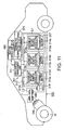
- Example 12 In an example 12, a vehicle of the example 12 having a configuration schematically shown in Fig. 11 , using the secondary battery of the embodiments 1 - 11, was manufactured.
- Fig. 11 is a diagram schematically showing a configuration of the vehicle of the example 12.
- a vehicle 300 shown in Fig. 11 is an electric car.
- the vehicle 300 shown in Fig. 11 is provided with a vehicle power source 301, a vehicle ECU (Electric Control Unit) 380 that is host control means of the vehicle power source 301, an outer terminal 370, an inverter 340, a drive motor 345.
- a vehicle ECU Electric Control Unit
- the vehicle 300 is mounted with the vehicle power source 301 in an engine room, on the backward portion in the car body of the car, or under the sheet, for example.
- the mounting place of the secondary batteries on the vehicle 300 is schematically shown in Fig. 11 .
- the vehicle power source 301 is provided with a plurality of (three, for example) battery packs 312a, 312b and 312c, a battery management unit (BMU: Battery Management Unit) 311, a communication bus 310.
- BMU Battery Management Unit
- the three battery packs 312a, 313b and 312c are electrically connected in series.
- the battery pack 312a is provided with an assembled battery 314a and an assembled battery monitor device (VTM: Voltage Temperature Monitoring) 313a.
- the battery pack 312b is provided with an assembled battery 314b and an assembled battery monitor device 313b.
- the battery pack 312c is provided with an assembled battery 314c and an assembled battery monitor device 313c.
- Each of the battery packs 312a, 312b and 312c can be detached independently, and can be changed for another battery pack.
- Each of the assembled batteries 314a - 314c is provided with a plurality of series-connected secondary batteries.
- Each of the secondary batteries is a battery which has been manufactured in the same manufacturing procedure as the manufacturing procedure of the secondary battery of the example 1.
- Each of the assembled batteries 314a - 314c is charged/discharged through a positive electrode terminal 316 and a negative electrode terminal 317.
- the battery management unit 31 in order to collect information relating to maintenance of the vehicle power source 301, performs communication of information such as voltages and temperatures of the secondary batteries in the assembled batteries 314a - 314c contained in the vehicle power source 301, with the assembled battery monitor devices 313a - 313c, to collect the information.
- the communication bus 310 is connected between the battery management unit 311 and the assembled battery monitor devices 313a - 313c.
- the communication bus 310 is configured so that a set of communication lines is shared by a plurality of nodes (the battery management unit and one or more assembled battery monitor devices).
- the communication bus is a communication bus configured based on the CAN (Control Area Network) standard.
- the assembled battery monitor devices 313a - 313c measure voltages and temperatures of the secondary batteries composing the assembled batteries 314a - 314c, respectively, based on an instruction by communication from the battery management unit 311. However, the temperature may be measured at several places for each assembled battery, and the temperatures of the all secondary batteries need not be measured.
- the vehicle power source 301 may have an electromagnetic contactor (a switch device 333 shown in Fig. 11 , for example) for switching the connection between the positive electrode terminal and the negative electrode terminal.
- the switch device 333 contains a precharge switch (not shown) which is turned ON when charging of the assembled batteries 314a - 314c is performed, and a main switch (not shown) which is turned ON when the battery output is supplied to a load.
- a precharge switch (not shown) which is turned ON when charging of the assembled batteries 314a - 314c is performed
- a main switch (not shown) which is turned ON when the battery output is supplied to a load.
- Each of the precharge switch and the main switch is provided with a relay circuit (not shown) which is turned ON and OFF by a signal supplied to a coil arranged in the vicinity of a switch element.
- the inverter 340 converts an inputted DC voltage into a three-phase high AC voltage for driving motor.
- the inverter 340 is controlled of its output voltage, based on a control signal from the battery management unit 311 described later, or a control signal from the vehicle ECU 380 for controlling the whole vehicle operation.
- the three-phase output terminals of the inverter 340 are respectively connected to the three-phase input terminals of the drive motor 345.
- the drive motor 345 is rotated by the power supplied from the inverter 340, and transmits the rotation to an axle and a drive wheel W, via a differential gear unit, for example.
- the vehicle 300 is provided with a regenerative braking mechanism which rotates the drive motor 345 when the vehicle 300 is braked, and converts the kinetic energy into the regenerative energy as the electric energy.
- the regenerative energy restored by the regenerative braking mechanism is inputted into the inverter 340, and is converted into a DC current.
- the DC current is inputted to the vehicle power source 301.
- connection line L1 One terminal of a connection line L1 is connected to the negative electrode terminal 317 of the vehicle power source 301.
- the other terminal of the connection line L1 is connected to a negative electrode input terminal of the inverter 340 via a current detection portion (not shown) in the battery management unit 311.
- connection line L2 One terminal of a connection line L2 is connected to the positive electrode terminal 316 of the vehicle power source 301, via the switch device 333.
- the other terminal of the connection line L2 is connected to a positive electrode input terminal of the inverter 340.
- the outer terminal 370 is connected to the battery management unit 311 described later.
- the outer terminal 370 may connect to an external power source, for example.
- the vehicle ECU 380 controls the battery management unit 311 in cooperation with another device, in response to an operation input by a driver or the like, and thereby manages the whole vehicle. Data relating to the maintenance of the vehicle power source 301 such as a remaining capacity or the like of the vehicle power source 301 is transferred by the communication line, between the battery management unit 311 and the vehicle ECU 380.
- the batteries are used in the vehicle 300 of Fig. 11 , and thereby the effect of the embodiment can be obtained.
Landscapes
- Chemical & Material Sciences (AREA)
- Chemical Kinetics & Catalysis (AREA)
- Electrochemistry (AREA)
- General Chemical & Material Sciences (AREA)
- Inorganic Chemistry (AREA)
- Engineering & Computer Science (AREA)
- Manufacturing & Machinery (AREA)
- Crystallography & Structural Chemistry (AREA)
- Secondary Cells (AREA)
Applications Claiming Priority (3)
| Application Number | Priority Date | Filing Date | Title |
|---|---|---|---|
| JP2017053457 | 2017-03-17 | ||
| EP17188752 | 2017-08-31 | ||
| JP2017172247A JP6942573B2 (ja) | 2017-03-17 | 2017-09-07 | 二次電池、電池パック及び車両 |
Publications (1)
| Publication Number | Publication Date |
|---|---|
| EP3376583A1 true EP3376583A1 (de) | 2018-09-19 |
Family
ID=61187233
Family Applications (1)
| Application Number | Title | Priority Date | Filing Date |
|---|---|---|---|
| EP18156915.3A Withdrawn EP3376583A1 (de) | 2017-03-17 | 2018-02-15 | Sekundärbatterie, batteriepack und fahrzeug |
Country Status (1)
| Country | Link |
|---|---|
| EP (1) | EP3376583A1 (de) |
Cited By (1)
| Publication number | Priority date | Publication date | Assignee | Title |
|---|---|---|---|---|
| CN109449494A (zh) * | 2018-11-06 | 2019-03-08 | 成都市银隆新能源产业技术研究有限公司 | 锂离子电池固体电解质界面层的制备方法和锂离子电池 |
Citations (4)
| Publication number | Priority date | Publication date | Assignee | Title |
|---|---|---|---|---|
| US20100216019A1 (en) * | 2007-10-12 | 2010-08-26 | Ryuta Morishima | Method for manufacturing secondary battery |
| US20110266489A1 (en) * | 1998-10-20 | 2011-11-03 | Fraunhofer-Gesellschaft Zur Forderung Der Angewandten Forschung E.V. | Paste-like mass with inorganic, liquid conductors and layers and electrochemical elements produced therefrom |
| WO2013094689A1 (ja) * | 2011-12-21 | 2013-06-27 | 日産化学工業株式会社 | 水系リチウムイオン二次電池 |
| US20140308544A1 (en) * | 2013-04-10 | 2014-10-16 | Alveo Energy, Inc. | Cosolvent electrolytes for electrochemical devices |
-
2018
- 2018-02-15 EP EP18156915.3A patent/EP3376583A1/de not_active Withdrawn
Patent Citations (4)
| Publication number | Priority date | Publication date | Assignee | Title |
|---|---|---|---|---|
| US20110266489A1 (en) * | 1998-10-20 | 2011-11-03 | Fraunhofer-Gesellschaft Zur Forderung Der Angewandten Forschung E.V. | Paste-like mass with inorganic, liquid conductors and layers and electrochemical elements produced therefrom |
| US20100216019A1 (en) * | 2007-10-12 | 2010-08-26 | Ryuta Morishima | Method for manufacturing secondary battery |
| WO2013094689A1 (ja) * | 2011-12-21 | 2013-06-27 | 日産化学工業株式会社 | 水系リチウムイオン二次電池 |
| US20140308544A1 (en) * | 2013-04-10 | 2014-10-16 | Alveo Energy, Inc. | Cosolvent electrolytes for electrochemical devices |
Non-Patent Citations (1)
| Title |
|---|
| HAEGYEOM KIM ET AL: "Aqueous Rechargeable Li and Na Ion Batteries", CHEMICAL REVIEWS, vol. 114, no. 23, 10 December 2014 (2014-12-10), US, pages 11788 - 11827, XP055414196, ISSN: 0009-2665, DOI: 10.1021/cr500232y * |
Cited By (2)
| Publication number | Priority date | Publication date | Assignee | Title |
|---|---|---|---|---|
| CN109449494A (zh) * | 2018-11-06 | 2019-03-08 | 成都市银隆新能源产业技术研究有限公司 | 锂离子电池固体电解质界面层的制备方法和锂离子电池 |
| CN109449494B (zh) * | 2018-11-06 | 2022-12-20 | 成都市银隆新能源产业技术研究有限公司 | 锂离子电池固体电解质界面层的制备方法和锂离子电池 |
Similar Documents
| Publication | Publication Date | Title |
|---|---|---|
| KR101889219B1 (ko) | 이차 전지, 전지 팩 및 차량 | |
| US10756392B2 (en) | Secondary battery, battery pack, and vehicle | |
| US10720667B2 (en) | Secondary battery, battery pack, and vehicle | |
| JP6873767B2 (ja) | 二次電池、電池パック及び車両 | |
| US10727540B2 (en) | Secondary battery, battery module, battery pack and vehicle | |
| EP3145018B1 (de) | Sekundärbatterie, verbundelektrolyt, batteriepack und fahrzeug | |
| US20180269538A1 (en) | Secondary battery, battery pack and vehicle | |
| EP3379624A1 (de) | Sekundärbatterie, batteriepack und fahrzeug | |
| US10461313B2 (en) | Nonaqueous electrolyte battery, battery module, and battery pack | |
| US11251414B2 (en) | Electrode group, secondary battery, battery pack, and vehicle | |
| CN107204455A (zh) | 二次电池、电池包及车辆 | |
| US20180269539A1 (en) | Electrode for secondary battery, secondary battery, battery pack, and vehicle | |
| EP3364491A1 (de) | Sekundärbatterie, batteriemodul, batteriepack und fahrzeug | |
| JP2019160734A (ja) | 組電池、電池パック、車両、及び、定置用電源 | |
| CN112615067B (zh) | 二次电池、电池包、车辆及固定用电源 | |
| JP2020043034A (ja) | 電極、二次電池、電池パック、車両及び定置用電源 | |
| JP2019169458A (ja) | 二次電池、電池パック、車両、及び定置用電源 | |
| JP7269149B2 (ja) | 二次電池、電池パック、車両、及び定置用電源 | |
| US11431035B2 (en) | Secondary battery, battery pack and vehicle | |
| EP3376583A1 (de) | Sekundärbatterie, batteriepack und fahrzeug | |
| US20240079576A1 (en) | Niobium-titanium-based oxide, electrode, secondary battery, battery pack, vehicle, and stationary power source | |
| CN108631009A (zh) | 二次电池、电池包和车辆 | |
| JP2018110127A (ja) | 組電池、電池パック及び車 |
Legal Events
| Date | Code | Title | Description |
|---|---|---|---|
| PUAI | Public reference made under article 153(3) epc to a published international application that has entered the european phase |
Free format text: ORIGINAL CODE: 0009012 |
|
| 17P | Request for examination filed |
Effective date: 20180215 |
|
| AK | Designated contracting states |
Kind code of ref document: A1 Designated state(s): AL AT BE BG CH CY CZ DE DK EE ES FI FR GB GR HR HU IE IS IT LI LT LU LV MC MK MT NL NO PL PT RO RS SE SI SK SM TR |
|
| AX | Request for extension of the european patent |
Extension state: BA ME |
|
| STAA | Information on the status of an ep patent application or granted ep patent |
Free format text: STATUS: THE APPLICATION IS DEEMED TO BE WITHDRAWN |
|
| 18D | Application deemed to be withdrawn |
Effective date: 20190320 |