EP3376429A1 - Rfid-lesegerät und verfahren zu seiner herstellung - Google Patents
Rfid-lesegerät und verfahren zu seiner herstellung Download PDFInfo
- Publication number
- EP3376429A1 EP3376429A1 EP18152623.7A EP18152623A EP3376429A1 EP 3376429 A1 EP3376429 A1 EP 3376429A1 EP 18152623 A EP18152623 A EP 18152623A EP 3376429 A1 EP3376429 A1 EP 3376429A1
- Authority
- EP
- European Patent Office
- Prior art keywords
- rfid reader
- millimeters
- inner part
- conductor loop
- antenna
- Prior art date
- Legal status (The legal status is an assumption and is not a legal conclusion. Google has not performed a legal analysis and makes no representation as to the accuracy of the status listed.)
- Granted
Links
Images


Classifications
-
- G—PHYSICS
- G06—COMPUTING OR CALCULATING; COUNTING
- G06K—GRAPHICAL DATA READING; PRESENTATION OF DATA; RECORD CARRIERS; HANDLING RECORD CARRIERS
- G06K7/00—Methods or arrangements for sensing record carriers, e.g. for reading patterns
- G06K7/10—Methods or arrangements for sensing record carriers, e.g. for reading patterns by electromagnetic radiation, e.g. optical sensing; by corpuscular radiation
- G06K7/10009—Methods or arrangements for sensing record carriers, e.g. for reading patterns by electromagnetic radiation, e.g. optical sensing; by corpuscular radiation sensing by radiation using wavelengths larger than 0.1 mm, e.g. radio-waves or microwaves
Definitions
- the present invention relates to an RFID reader (RFID - radiofrequency identification), also referred to as RFID reader, in particular for multi-function cards, for example, for cards with integrated sensors for camera cards or generally for ID documents with biometric authentication.
- RFID reader RFID - radiofrequency identification
- the invention also relates to a method for producing an RFID reader.
- An exemplary RFID arrangement comprises a transponder which transmits at least one identifying code or further data, and a reading device for reading out this identifier or for reading and writing data.
- the communication or coupling between the transponder and the reader takes place by means of a high-frequency alternating electromagnetic field generated by the reading device.
- Data is transmitted and, if necessary, the transponder is supplied with energy.
- the transmission of the information takes place, for example, according to the standard ISO 14443 at a frequency of 13.56 MHz.
- ID documents in the form of an ID card such as in particular as an identity card, driver's license, passport or company ID are known.
- mobile phones, wearable devices, ID tokens, bank cards, entrance tickets or other RFID documents can be read with an RFID reader.
- RFID readers for contactless ID cards are generally known and widely used. They are mainly used for access, access, digital Applications and payment functions used. Examples of RFID readers include in DE 10 2009 027 123 A1 and DE 10 2009 045 186 A1 disclosed.
- ID cards with advanced features and additional components, such as: As displays, sensors, cameras, microphones, speakers or keyboards (see also ISO 18328-2 / ISO 17839-2).
- ID cards with integrated fingerprint sensors and face detection cameras are known which allow user-friendly acquisition of biometric data and, if necessary, biometric authentication on the card itself.
- Such cards are held on an RFID reader, whereupon the fingerprint is detected by the fingerprint sensor of the ID card or the face of the user by the camera and extracted biometric data for checking the access authorization of the holder of the ID card or by the ID Card itself created test result of the biometric data to the RFID reader are transmitted.
- the RFID reader comprises a housing and at least one antenna arranged in the housing.
- the antenna is formed from at least one conductor loop.
- the conductor loop has a central axis. It thus runs around the central axis or defines the central axis. In particular, the center axis can be aligned parallel to a surface normal to an extension plane of the conductor loop be.
- the conductor loop also has a height h in a direction perpendicular to the central axis extending longitudinal direction and a width b in a direction perpendicular to the longitudinal direction and perpendicular to the central axis extending transverse direction. In other words, the central axis, the longitudinal direction and the transverse direction are perpendicular to each other.
- the height h is greater than the width b.
- the center axis is a reference axis, not a physical device.
- the conductor loop and thus the antenna of the RFID reader are in this, the preferred case in the vertical direction higher than it is wide in the horizontal direction.
- the invention is based on the insight and includes that reproducible results and a particularly reliable face recognition are achieved using a camera-type ID card when the camera is at least about the same height as the face of the ID card to be designated Person is held.
- conventional RFID readers are square in shape and so narrowly dictate the location where the ID card must be held during face recognition. This forces a user to bring his face up to the height of the reader, resulting in limited ease of use and degraded face recognition function due to unnatural head posture.
- the invention has the advantage that the design of the antenna and the housing allows the use of a contactless ID card at different heights.
- the RFID reader according to the invention allows in particular the use in connection with ID cards with camera function by people of different sizes or wheelchair users.
- the height h of the conductor loop can be at least twice as large as the width b.
- the width b of the conductor loop and thus the antenna between 40 millimeters and 100 millimeters (40 millimeters ⁇ b ⁇ 100 millimeters), preferably 60 millimeters, and / or the height h of the conductor loop and thus the antenna is between 200 millimeters and 1000 millimeters (200 millimeters ⁇ h ⁇ 1000 Mm), preferably 500 mm.
- This sizing covers typical differences in the height of the field of view when the antenna is mounted at an appropriate height (for example, 1000 millimeters above the ground) or at least one conductor loop is located at such a height.
- the height h of the conductor loop is at least three times, for example four times or five times, as large as the width b.
- the housing may include a front panel, a back panel, and an inner member disposed in the direction of the center axis between the front panel and the back panel.
- the inner part can preferably also be designed as a plate.
- the antenna and / or at least one electronic component may be arranged.
- the at least one electronic component may comprise a control electronics and / or at least one light source, such as a number of LEDs, and / or connection cables, etc. Due to the arrangement of the technical components, in particular of the electronic components, in the inner part, these components are easily accessible via the front panel and / or the back panel.
- the housing comprises a transparent ausgestaltetes inner part.
- the front panel and rear panel can not be made transparent.
- the RFID reader comprises a number of LEDs, which are arranged in the housing so that they emit light during its operation through the transparent inner part, preferably radiate in the radial direction with respect to the central axis, in particular emit to the outside.
- a luminous edge can be achieved.
- the RFID reader is clearly visible to users, while at the same time an appealing design is achieved.
- the reader can indicate a denial of access by red light and a green light access grant.
- An operational readiness of the RFID reader can be displayed, for example, by white, yellow or blue light.
- the RFID reader comprises at least one passage opening arranged in the interior of the conductor loop.
- the at least one conductor loop of the antenna extends around the passage opening.
- the passage opening may comprise a central axis which runs parallel to the central axis of the conductor loop.
- different shapes of the through hole are possible.
- the passage opening has a shape adapted to the shape of the conductor loop and / or to the shape of the antenna.
- the passage opening may be oval shaped. Due to the open design achieved by the passage opening, in particular in combination with a transparent, light-emitting inner part, the RFID reader is easily visually recognizable. In this variant, light can be radiated both radially inwards and radially outwards.
- the passage opening may have a height h D in the longitudinal direction and a width b D in the transverse direction, the height h D being greater than the width b D , that is to say h D > b D.
- the passage opening can be twice as long as it is wide.
- the passage opening is 30 millimeters to 90 millimeters wide (30 millimeters ⁇ bp ⁇ 90 millimeters), preferably 50 millimeters wide and / or 190 millimeters to 950 millimeters (190 millimeters ⁇ h D ⁇ 950 millimeters), preferably 450 millimeters high , This dimensioning is adapted to the preferred dimensioning of the conductor loop or the antenna.
- the RFID reader comprises at least one lasered plastic plate.
- the inner part and / or the front plate and / or the rear plate can be configured as a lasered plastic plate. This allows a simple and inexpensive production.
- the RFID reader comprises a stand base. This allows a flexible spatial use of the RFID reader and saves mounting on walls or components.
- the height of the antenna is fixed and can be normalized for different applications or locations.
- the RFID reader may include at least one means for attaching the RFID reader to a wall or component.
- the RFID reader can in principle be designed for use for data exchange or communication with active or passive RFID transponders. It may in particular be designed for data exchange or communication with ID cards and / or camera cards with face recognition and / or portable devices.
- the RFID reader may be designed to operate at a carrier frequency of 13.56 MHz.
- the RFID reader can be designed for operation in accordance with the standard ISO 14443, ISO 18092, ISO 21481 ISO, 18000-3. The reader can thus also be used for Near Field Communication (NFC) applications. This opens up a wide range of applications. Mobile phones, smartwatches or other wearables can also be used with the RFID reader.
- NFC Near Field Communication
- the RFID reader preferably comprises an antenna with only one conductor loop, in particular for operation with a carrier frequency of 13.56 MHz. In this case, it is particularly simple and therefore inexpensive to produce.
- the RFID reader according to the invention has in summary the following advantages: It represents a combined RFID reader, which is suitable for using an ID card of different heights at an access point, machine or workstation. This allows a comfortable, barrier-free use of contactless ID cards for small people or tall people or wheelchair users. Thus, instead of several readers mounted at different heights, only one reading device is required.
- the RFID reader is easily visually recognizable by an open design.
- the RFID reader is also easy to install on a wall, a machine, on a pillar or as a floor standing unit in the workplace.
- lasered plastic plates for example for the front panel, the inner part, which can be equipped with antenna and electronics, and the back plate, allows a very simple structure and thus a cost-effective production.
- the RFID reader is also convenient and flexible for use with camera cards with face recognition as well as conventional ID cards.
- the inventive method for producing a previously described RFID reader according to the invention comprises the step that at least one plate is cut to produce the housing by means of a laser.
- a plastic plate is used as the plate.
- a front plate, a back plate and an inner part are manufactured, so in particular cut by means of a laser.
- the inner part can be arranged in the direction of the central axis between the front plate and the rear plate.
- the plates can, for example, releasably fixedly connected to each other, in particular screwed. Alternatively or additionally, the plates may be non-releasably bonded together, for example glued or soldered or welded together.
- the antenna and / or at least one electronic component be arranged, advantageously before the inner part is connected to the front panel and the back plate.
- the inventive method has the advantage that it allows a particularly simple and inexpensive production of an RFID reader according to the invention.
- FIGS. 1 to 4 An embodiment of the present invention, taking into account further embodiments, will be described below with reference to FIGS. 1 to 4 explained in more detail. Corresponding components are identified by the same reference numerals.
- the FIG. 1 schematically shows an inventive RFID reader 10 in a perspective view.
- the reader 10 comprises a housing 11 and a stand base 12.
- the housing 11 comprises a central axis 16, a longitudinal direction 17 and a transverse direction 18, which are perpendicular to each other.
- the longitudinal direction 17 is vertical and the transverse direction 18 is aligned horizontally.
- an antenna and other electronic components or components are arranged (see FIG. 3 ).
- the antenna 22 or at least one conductor loop forming the antenna has the central axis 16 or defines the central axis 16.
- the conductor loop is higher in the longitudinal or vertical direction 17 than it is wide in the transverse direction or horizontal direction 18 and thereby makes possible Use of the reader 10 for contactless transponders, in particular ID cards with integrated face recognition camera, at different heights.
- the stand base 12 is optional.
- the reading device 10 may include means for attaching the reader 10 to a wall, to a machine, to a door, or to another component.
- the housing 11 comprises a front plate 13, a back plate 15 and an inner part 14 arranged in the direction of the center axis 16 between the front plate 13 and the back plate 15.
- the inner part 14 is preferably made transparent and forms at least part of the lateral surface of the housing 11.
- one or more light sources for example, a number of LEDs that are configured and arranged so that they light through the transparent inner part 14 laterally, ie in particular in a plane on which the central axis 16 is perpendicular to the outside can radiate. This allows a good visual recognition of the reader while appealing design.
- the reader 10 shown has a basically optional through-opening 25. At least one runs Conductor loop of the antenna around the passage opening 25 or the passage opening is arranged within the conductor loop. Variants without through-hole or with multiple through holes are also possible. However, the through-hole has the advantage that it promotes the visual recognition of the reader by the resulting open design. At the same time, this design requires less material than a closed version and thus saves material costs.
- the shape of the through hole and its size are basically variable selectable. In addition to the oval shape shown also angular shapes or curved shapes are possible. The preferred shape and size of the passage opening is in connection with the Figures 2 and 3 explained in more detail.
- the stand base 12 is in the FIG. 1 shown in the form of a circular disc. Other configurations of the stand base are also possible, for example a square shape or the provision of a number of stand feet.
- the stand base comprises a base plate 19, an inner part 20 and a cover plate 21.
- the inner part 20 is arranged between the base plate 19 and the cover plate 21. It is preferably designed to be transparent and arranged so that it forms at least part of the outward and possibly the side surfaces of the stand base 12 pointing to a passage opening 25.
- the base plate 19 and the cover plate 21 are preferably not made transparent.
- one or more light sources in the reader 10 are arranged so that they can emit light through the transparent inner part 20 laterally. This has the advantage that the reading device 10 is clearly visually perceptible and user guidance can be realized by the light. Furthermore, the reader 10 gets an attractive appearance by the illumination from the inside.
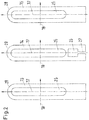
- the FIG. 2 schematically shows the front panel 13, the inner part 14 and the back plate 15 of the RFID reader 10, each in a side view.
- the Front plate 13 and the back plate 15 are identical.
- the inner part 14, unlike the front plate 13 and the back plate 15 in the longitudinal direction 17 below the passage opening 25 has a cavity or opening 26 and an access channel 27.
- the access channel 27 provides access, for example from below, to the cavity 26 through which electronic components disposed in the cavity 26 can be contacted.
- the inner part is preferably transparent.
- the front plate 13, the back plate 15 and the middle part 14 are the same height in the longitudinal direction 17, the same width in the transverse direction 18 and have an identically positioned and identically dimensioned passage opening 25.
- the upper region 28 can in principle also be shaped differently.
- the front plate 13, the back plate 15 and the inner part 14 can be superimposed in the direction of the central axis 16 and secured to each other due to their identical dimensioning in the longitudinal direction 17 and transverse direction 18 or in the plane spanned by these directions, for example, screwed or glued together.
- the assembly and thus the production of the reader are therefore simple and inexpensive.
- the front plate 13, the back plate 15 and the inner part 14 may also be plastic plates, preferably lasered plastic plates.
- FIG. 3 schematically shows the inner part 14 with components arranged therein in a plan view.
- an antenna 22 is arranged, which is formed from at least one conductor loop.
- the conductor loop is arranged around the central axis 16.
- the antenna 22 or the conductor loop has a height h in the longitudinal direction 17 and a width b in the transverse direction 18, wherein the height h is greater than the width b.
- the height h of the conductor loop can be at least twice as large as the width b.
- the conductor loop and thus the antenna 22 is 40 millimeters to 100 millimeters wide (40 millimeters ⁇ b ⁇ 100 millimeters), preferably 60 millimeters wide and / or 200 millimeters to 1000 Mm (200 mm ⁇ h ⁇ 1000 mm), preferably 500 mm high.
- the passage opening 25 may have a height h D in the longitudinal direction 17 and a width b D in the transverse direction 18, the height h D being greater than the width b D , that is to say h D > b D.
- the passage opening 25 may be twice as long as it is wide.
- the passage opening 25 is 30 millimeters to 90 millimeters wide (30 millimeters ⁇ b D ⁇ 90 millimeters), preferably 50 millimeters wide and / or 190 millimeters to 950 millimeters (190 millimeters ⁇ h D ⁇ 950 millimeters), preferably 450 Millimeters high. This dimensioning is adapted to the preferred dimensioning of the conductor loop or the antenna 22.
- the reader 10 can be designed for operation with a carrier frequency of 13.56 MHz.
- the antenna may comprise only one conductor loop or be formed from only one conductor loop.
- lower portion of the inner part 14 are electronic components, for example, a control electronics 23 with optional LEDs for illuminating the inner part 14 and connecting cable 24, respectively.
- the connection cable or cables can be guided in particular through the access channel 27.
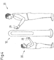
- the FIG. 4 schematically shows an application of the RFID reader according to the invention 10.
- the reader 10 is, for example, placed on a secure access to a building or otherwise mounted there. Users 30 and 31 of different height or wheelchair users must identify themselves with ID cards 29 with integrated facial recognition camera in order to gain access. Due to the inventive design of the reader 10 with only one reader 10, a use in very different heights possible, while still a camera of an ID card 29 at the height of the face of the user 30 and 31 can be maintained.
- a mobile phone with a biometric authentication by use an integrated camera and / or a fingerprint sensor can be used by users 30 and 31 for identification.
- the required data can be transmitted via NFC to the reader or to a background system, for example.
- the inventive method for producing a previously described RFID reader 10 at least one plate, so in particular the front plate 13 and / or the inner part 14 and / or the back plate 15 is cut to manufacture the housing 11 by means of a laser.
- plastic plates are used as plates.
- the inner part 14 is advantageously arranged in the direction of the central axis 16 between the front plate 13 and the rear plate 15.
- the plates (13, 14, 15) can be releasably firmly connected to each other, in particular screwed.
- the plates may be non-releasably bonded together, for example glued or soldered or welded together.
- the antenna 22 and / or at least one electronic component 23 and 24 can be arranged, advantageously before the inner part 14 is connected to the front plate 13 and the rear plate 15.
- the method enables a particularly simple and cost-effective production of the RFID reader 10 according to the invention.
Landscapes
- Health & Medical Sciences (AREA)
- Toxicology (AREA)
- Physics & Mathematics (AREA)
- Engineering & Computer Science (AREA)
- Electromagnetism (AREA)
- General Health & Medical Sciences (AREA)
- Artificial Intelligence (AREA)
- Computer Vision & Pattern Recognition (AREA)
- General Physics & Mathematics (AREA)
- Theoretical Computer Science (AREA)
- Support Of Aerials (AREA)
- Details Of Aerials (AREA)
Abstract
Description
- Die vorliegende Erfindung betrifft ein RFID-Lesegerät (RFID - radiofrequency identification), auch als RFID-Reader bezeichnet, insbesondere für Multifunktionskarten, zum Beispiel für Karten mit integrierter Sensorik, für Kamerakarten oder allgemein für ID-Dokumente mit biometrischer Authentifizierung. Die Erfindung betrifft außerdem ein Verfahren zur Herstellung eines RFID-Lesegeräts.
- Eine beispielhafte RFID-Anordnung umfasst einen Transponder, der mindestens einen kennzeichnenden bzw. identifizierenden Code bzw. weitere Daten übermittelt, und ein Lesegerät zum Auslesen dieser Kennung oder zum Lesen und Schreiben von Daten. Die Kommunikation bzw. Kopplung zwischen Transponder und Lesegerät erfolgt durch ein vom Lesegerät erzeugtes hochfrequentes elektromagnetisches Wechselfeld. Dabei werden Daten übertragen und gegebenenfalls der Transponder mit Energie versorgt. Die Übertragung der Information erfolgt zum Beispiel nach der Norm ISO 14443 bei einer Frequenz von 13,56 MHz.
- Aktive ID-Karten, die komplexe Systeme mit einem Mikroprozessor, einem Karten-Betriebssystem und kryptografischen Fähigkeiten enthalten, finden eine stetig zunehmende Verbreitung. So sind beispielsweise Ausweisdokumente in Form einer ID-Karte, wie insbesondere als Personalausweis, Führerschein, Reisepass oder Firmenausweis bekannt. Aber auch Mobiltelefone, tragbare Vorrichtungen (Wearables), ID-Token, Bankkarten, Eintrittskarten oder sonstige RFID-Dokumente können mit einem RFID-Lesegerät auslesbar sein..
- RFID-Lesegeräte für kontaktlose ID-Karten sind grundsätzlich bekannt und weit verbreitet. Sie werden vor allem für Zutritt, Zugang, digitale Anwendungen und Bezahlfunktionen verwendet. Beispiele für RFID-Lesegeräte sind unter anderem in
DE 10 2009 027 123 A1 undDE 10 2009 045 186 A1 offenbart. - Es ist ein Trend zu ID-Karten mit erweiterten Funktionen und zusätzlichen Komponenten, wie z. B. Displays, Sensoren, Kameras, Mikrofonen, Lautsprechern oder Tastaturen zu verzeichnen (siehe auch ISO 18328-2 / ISO 17839-2). So sind ID-Karten mit integrierten Fingerabdrucksensoren und Kameras zur Gesichtserfassung bekannt, die eine benutzerfreundliche Erfassung biometrischer Daten sowie ggf. eine biometrische Authentisierung auf der Karte selbst erlauben. Solche Karten werden an ein RFID-Lesegerät gehalten, woraufhin der Fingerabdruck durch den Fingerabdrucksensor der ID-Karte oder das Gesicht des Benutzers durch die Kamera erfasst und daraus extrahierte biometrische Daten zur Überprüfung einer Zugangsberechtigung des Inhabers der ID-Karte oder ein durch die ID-Karte selbst erstelltes Prüfergebnis der biometrischen Daten an das RFID-Lesegerät übermittelt werden.
- Vor dem beschriebenen Hintergrund ist es Aufgabe der vorliegenden Erfindung, ein verbessertes RFID-Lesegerät und ein Verfahren zu seiner Herstellung zur Verfügung zu stellen.
- Die Aufgabe wird durch ein RFID-Lesegerät nach Anspruch 1 und ein Verfahren nach Anspruch 12 gelöst. Die abhängigen Ansprüche enthalten weitere, vorteilhafte Ausgestaltungen der Erfindung.
- Das erfindungsgemäße RFID-Lesegerät umfasst ein Gehäuse und mindestens eine in dem Gehäuse angeordnete Antenne. Die Antenne wird aus mindestens einer Leiterschleife gebildet. Die Leiterschleife weist eine Mittelachse auf. Sie verläuft also um die Mittelachse herum bzw. definiert die Mittelachse. Insbesondere kann die Mittelachse parallel zu einer Flächennormalen auf eine Erstreckungsebene der Leiterschleife ausgerichtet sein. Die Leiterschleife weist zudem eine Höhe h in einer senkrecht zur Mittelachse verlaufenden Längsrichtung und eine Breite b in einer senkrecht zur Längsrichtung und senkrecht zur Mittelachse verlaufenden Querrichtung auf. Mit anderen Worten stehen die Mittelachse, die Längsrichtung und die Querrichtung jeweils senkrecht aufeinander. Die Höhe h ist größer als die Breite b.
- Bei der Mittelachse handelt es sich um eine Bezugsachse, also nicht um ein physisches Bauelement. Vorzugsweise verlaufen die Längsrichtung in vertikaler Richtung und die Querrichtung in horizontaler Richtung. Die Leiterschleife und damit die Antenne des RFID-Lesegeräts sind in diesem, bevorzugten Fall also in vertikaler Richtung höher als sie in horizontaler Richtung breit ist.
- Die Erfindung beruht auf der Erkenntnis und schließt diese mit ein, dass reproduzierbare Ergebnisse und eine besonders zuverlässige Gesichtserkennung unter Verwendung einer ID-Karte mit Kamerafunktion erreicht werden, wenn die Kamera auf wenigstens ungefähr der gleichen Höhe wie das Gesicht der durch die ID-Karte auszuweisenden Person gehalten wird. Herkömmliche RFID-Lesegeräte sind jedoch quadratisch ausgebildet und geben so den Ort, an dem die ID-Karte während der Gesichtserkennung gehalten werden muss, in engen Grenzen vor. Dadurch wird ein Benutzer genötigt, sein Gesicht auf die Höhe des Lesegerätes zu bringen, was einen eingeschränkten Benutzungskomfort und eine durch die unnatürliche Kopfhaltung bedingte verschlechterte Gesichtserkennungsfunktion bedingt. Die Erfindung hat vor diesem Hintergrund den Vorteil, dass durch die Gestaltung der Antenne und des Gehäuses die Benutzung einer kontaktlosen ID-Karte in verschiedenen Höhen ermöglicht wird. Damit gestattet das erfindungsgemäße RFID-Lesegerät insbesondere die Benutzung im Zusammenhang mit ID-Karten mit Kamerafunktion durch unterschiedlich große Personen oder Rollstuhlfahrer.
- Die Höhe h der Leiterschleife kann mindestens doppelt so groß wie die Breite b sein. In einer vorteilhaften Variante beträgt die Breite b der Leiterschleife und damit der Antenne zwischen 40 Millimeter und 100 Millimeter (40 Millimeter ≤ b ≤ 100 Millimeter), vorzugsweise 60 Millimeter, und/oder beträgt die Höhe h der Leiterschleife und damit der Antenne zwischen 200 Millimeter und 1000 Millimeter (200 Millimeter ≤ h ≤ 1000 Millimeter), vorzugsweise 500 Millimeter. Diese Dimensionierung deckt typische Unterschiede in der Höhe des Gesichtsfeldes ab, wenn die Antenne in einer entsprechenden Höhe (zum Beispiel 1000 Millimeter über dem Boden) angebracht ist oder die mindestens eine Leiterschleife in einer solchen Höhe angeordnet ist. In einer weiteren Variante ist die Höhe h der Leiterschleife mindestens dreimal, zum Beispiel viermal oder fünfmal, so groß wie die Breite b.
- Das Gehäuse kann eine Frontplatte, eine Rückplatte und ein in Richtung der Mittelachse zwischen der Frontplatte und der Rückplatte angeordnetes Innenteil umfassen. Das Innenteil kann vorzugsweise ebenfalls als Platte ausgestaltet sein. In dem Innenteil können zum Beispiel die Antenne und/oder mindestens eine elektronische Komponente angeordnet sein. Die mindestens eine elektronische Komponente kann eine Ansteuerungselektronik und/oder mindestens eine Lichtquelle, wie beispielsweise eine Anzahl an LEDs, und/oder Anschlusskabel usw. umfassen. Durch die Anordnung der technischen Komponenten, insbesondere der elektronischen Komponenten, im Innenteil sind diese Komponenten über die Frontplatte und/oder über die Rückplatte leicht zugänglich.
- In einer bevorzugten Variante umfasst das Gehäuse ein transparent ausgestaltetes Innenteil. Dabei können die Frontplatte und Rückplatte nicht transparent ausgestaltet sein.
- Vorteilhafterweise umfasst das RFID-Lesegerät eine Anzahl LEDs, die in dem Gehäuse so angeordnet sind, dass sie bei ihrem Betrieb Licht durch das transparente Innenteil abstrahlen, vorzugsweise in radialer Richtung bezüglich der Mittelachse abstrahlen, insbesondere nach außen abstrahlen. Auf diese Weise kann ein leuchtender Rand erzielt werden. Dadurch ist das RFID-Lesegerät für Nutzer gut sichtbar, wobei gleichzeitig ein ansprechendes Design erzielt wird. Durch eine Farbe des von den LEDs abgestrahlten Lichts kann eine Benutzerführung erreicht werden. So kann das Lesegerät eine Zutrittsverweigerung durch rotes Licht und eine Zutrittsgewährung durch grünes Licht anzeigen. Eine Betriebsbereitschaft des RFID-Lesegerätes kann beispielsweise durch weißes, gelbes oder blaues Licht angezeigt werden.
- In einer weiteren, bevorzugten Variante umfasst das RFID-Lesegerät mindestens eine im Inneren der Leiterschleife angeordnete Durchgangsöffnung. Mit anderen Worten verläuft die mindestens eine Leiterschleife der Antenne um die Durchgangsöffnung herum. Dabei kann die Durchgangsöffnung eine Mittelachse umfassen, die parallel zur Mittelachse der Leiterschleife verläuft. Prinzipiell sind verschiedene Formgestaltungen der Durchgangsöffnung möglich. Im Hinblick auf ein ansprechendes Design und einen möglichst geringen Materialeinsatz, also auch zur Reduzierung von Herstellungskosten, ist es vorteilhaft, wenn die Durchgangsöffnung eine an die Form der Leiterschleife und/oder an die Form der Antenne angepasste Form aufweist. Beispielsweise kann die Durchgangsöffnung oval geformt sein. Durch die durch die Durchgangsöffnung erzielte offene Formgestaltung, insbesondere in Kombination mit einem transparenten, Licht abstrahlenden Innenteil, ist das RFID-Lesegerät leicht visuell erkennbar. In dieser Variante kann Licht sowohl radial nach innen als auch radial nach außen abgestrahlt werden.
- Die Durchgangsöffnung kann in Längsrichtung eine Höhe hD und in Querrichtung eine Breite bD aufweisen, wobei die Höhe hD größer ist als die Breite bD, also hD > bD. Insbesondere kann die Durchgangsöffnung doppelt so lang sein wie sie breit ist. In einer vorteilhaften Variante ist die Durchgangsöffnung 30 Millimeter bis 90 Millimeter breit (30 Millimeter ≤ bp ≤ 90 Millimeter), vorzugsweise 50 Millimeter breit und/oder 190 Millimeter bis 950 Millimeter (190 Millimeter ≤ hD ≤ 950 Millimeter), vorzugsweise 450 Millimeter hoch. Diese Dimensionierung ist an die bevorzugte Dimensionierung der Leiterschleife bzw. der Antenne angepasst.
- In einer weiteren Variante umfasst das RFID-Lesegerät mindestens eine gelaserte Plastikplatte. Dabei können das Innenteil und/oder die Frontplatte und/oder die Rückplatte als gelaserte Plastikplatte ausgestaltet sein. Dies ermöglicht eine einfache und kostengünstige Herstellung.
- Vorteilhafterweise umfasst das RFID-Lesegerät einen Ständerfuß. Dies ermöglicht einen flexiblen räumlichen Einsatz des RFID-Lesegeräts und erspart das Anbringen an Wänden oder Bauteilen. Zudem ist die Höhe der Antenne festgelegt und kann so für verschiedene Anwendungen oder Einsatzorte normiert werden. Zusätzlich oder alternativ dazu kann das RFID-Lesegerät mindestens ein Mittel zur Befestigung des RFID-Lesegeräts an einer Wand oder einem Bauteil umfassen.
- Das RFID-Lesegerät kann prinzipiell zur Verwendung für einen Datenaustausch bzw. eine Kommunikation mit aktiven oder passiven RFID-Transpondern ausgelegt sein. Es kann insbesondere für einen Datenaustausch bzw. eine Kommunikation mit ID-Karten und/oder Kamerakarten mit Gesichtserkennung und/oder tragbare Vorrichtungen ausgelegt sein. Zum Beispiel kann das RFID-Lesegerät zum Betrieb mit einer Trägerfrequenz von 13,56 MHz ausgelegt sein. Weiterhin kann das RFID-Lesegerät für einen Betrieb nach der Norm ISO 14443, ISO 18092, ISO 21481 ISO, 18000-3 ausgelegt sein. Das Lesegerät kann damit auch für Anwendungen der Near Field Communication (NFC) genutzt werden. Dies eröffnet ein weites Anwendungsspektrum. Es können auch Mobiltelefone, Smartwatches oder andere Wearables mit dem RFID-Lesegerät verwendet werden.
- Das RFID-Lesegerät umfasst vorzugsweise eine Antenne mit nur einer Leiterschleife, insbesondere für einen Betrieb mit einer Trägerfrequenz von 13,56 MHz. In diesem Fall ist es besonders einfach aufgebaut und daher kostengünstig herstellbar.
- Das erfindungsgemäße RFID-Lesegerät hat zusammenfassend die folgenden Vorteile: Es stellt ein kombiniertes RFID-Lesegerät dar, welches für die Verwendung einer ID-Karte in verschiedenen Höhen an einem Zugangspunkt, einer Maschine oder einem Arbeitsplatz geeignet ist. Dabei wird eine komfortable, barrierefreie Verwendung von kontaktlosen ID-Karten für kleine Personen oder große Personen oder Rollstuhlfahrer ermöglicht. Es ist somit anstelle von mehreren, in verschiedenen Höhen angebrachten Lesegeräten nur noch ein Lesegerät erforderlich.
- Weiterhin ist das RFID-Lesegerät durch eine offene Formgestaltung leicht visuell erkennbar. Das RFID-Lesegerät ist darüber hinaus einfach an einer Wand, einer Maschine, auf einer Säule oder als Standgerät am Arbeitsplatz installierbar.
- Die Verwendung von gelaserten Plastikplatten, zum Beispiel für die Frontplatte, das Innenteil, welches mit Antenne und Elektronik ausgestattet sein kann, und die Rückplatte, ermöglicht einen sehr einfachen Aufbau und damit eine kostengünstige Herstellung.
- Das RFID-Lesegerät ist zudem komfortabel und flexibel verwendbar sowohl für Kamerakarten mit Gesichtserkennung als auch für konventionelle ID-Karten.
- Das erfindungsgemäße Verfahren zur Herstellung eines zuvor beschriebenen erfindungsgemäßen RFID-Lesegeräts umfasst den Schritt, dass mindestens eine Platte zur Fertigung des Gehäuses mittels eines Lasers zugeschnitten wird. Bevorzugt wird als Platte eine Plastikplatte verwendet. In einer vorteilhaften Variante werden eine Frontplatte, eine Rückplatte und ein Innenteil gefertigt, also insbesondere mittels eines Lasers zugeschnitten. Zur Bildung des Gehäuses kann das Innenteil in Richtung der Mittelachse zwischen der Frontplatte und der Rückplatte angeordnet werden. Die Platten können zum Beispiel lösbar fest miteinander verbunden werden, insbesondere verschraubt werden. Alternativ dazu oder zusätzlich können die Platten nicht lösbar fest miteinander verbunden werden, zum Beispiel aneinander geklebt oder gelötet oder geschweißt werden. In dem Innenteil können die Antenne und/oder mindestens eine elektronische Komponente angeordnet werden, vorteilhafterweise bevor das Innenteil mit der Frontplatte und der Rückplatte verbunden wird. Das erfindungsgemäße Verfahren hat den Vorteil, dass es eine besonders einfache und kostengünstige Herstellung eines erfindungsgemäßen RFID-Lesegeräts ermöglicht.
- Weitere Merkmale, Eigenschaften und Vorteile der vorliegenden Erfindung werden im Folgenden anhand von Ausführungsvarianten unter Bezugnahme auf die beigefügten Figuren näher beschrieben. Alle bisher und im Folgenden beschriebenen Merkmale sind dabei sowohl einzeln als auch in einer beliebigen Kombination miteinander vorteilhaft. Die im Folgenden beschriebenen Ausführungsvarianten stellen lediglich Beispiele dar, welche den Gegenstand der Erfindung jedoch nicht beschränken.
- Fig. 1
- zeigt schematisch ein erfindungsgemäßes RFID-Lesegerät in einer perspektivischen Ansicht.
- Fig. 2
- zeigt schematisch eine Frontplatte, ein Innenteil und eine Rückplatte eines erfindungsgemäßen RFID-Lesegeräts, jeweils in einer Seitenansicht.
- Fig. 3
- zeigt schematisch das Innenteil mit darin angeordneten Komponenten in einer Seitenansicht.
- Fig. 4
- zeigt schematisch eine Anwendung des erfindungsgemäßen RFID-Lesegeräts.
- Ein Ausführungsbeispiel der vorliegenden Erfindung unter Berücksichtigung von weiteren Ausführungsvarianten wird im Folgenden anhand der
Figuren 1 bis 4 näher erläutert. Einander entsprechende Komponenten werden dabei mit denselben Bezugsziffern gekennzeichnet. - Die
Figur 1 zeigt schematisch ein erfindungsgemäßes RFID-Lesegerät 10 in einer perspektivischen Ansicht. Das Lesegerät 10 umfasst ein Gehäuse 11 und einen Ständerfuß 12. Das Gehäuse 11 umfasst eine Mittelachse 16, eine Längsrichtung 17 und eine Querrichtung 18, die jeweils senkrecht aufeinander stehen. Vorzugsweise ist die Längsrichtung 17 vertikal und die Querrichtung 18 horizontal ausgerichtet. - In dem Gehäuse 11 sind eine Antenne und weitere elektronische Bauteile bzw. Komponenten angeordnet (siehe
Figur 3 ). Die Antenne 22 bzw. mindestens eine, die Antenne bildende Leiterschleife weist die Mittelachse 16 auf bzw. definiert die Mittelachse 16. Die Leiterschleife ist in Längsrichtung bzw. vertikaler Richtung 17 höher als sie in Querrichtung bzw. horizontaler Richtung 18 breit ist und ermöglicht dadurch die Benutzung des Lesegeräts 10 für kontaktlose Transponder, insbesondere ID-Karten mit integrierter Kamera zur Gesichtserkennung, in verschiedenen Höhen. Der Ständerfuß 12 ist optional. Alternativ zu dem inFigur 1 gezeigten Ständerfuß 12 kann das Lesegerät 10 Mittel zur Befestigung des Lesegeräts 10 an einer Wand, an einer Maschine, an einer Tür oder an einer anderen Komponente umfassen. - Das Gehäuse 11 umfasst eine Frontplatte 13, eine Rückplatte 15 und ein in Richtung der Mittelachse 16 zwischen der Frontplatte 13 und der Rückplatte 15 angeordnetes Innenteil 14. Das Innenteil 14 ist vorzugsweise transparent ausgestaltet und bildet zumindest einen Teil der seitlichen Oberfläche des Gehäuses 11. Vorteilhafterweise sind in dem Gehäuse 11 eine oder mehrere Lichtquellen angeordnet, zum Beispiel eine Anzahl LEDs, die so ausgestaltet und angeordnet sind, dass sie Licht durch das transparente Innenteil 14 seitlich, also insbesondere in einer Ebene, auf der die Mittelachse 16 senkrecht steht, nach außen abstrahlen können. Dies ermöglicht eine gute visuelle Erkennbarkeit des Lesegeräts bei gleichzeitig ansprechendem Design.
- Das in der
Figur 1 gezeigte Lesegerät 10 weist zudem eine grundsätzlich optionale Durchgangsöffnung 25 auf. Dabei verläuft mindestens eine Leiterschleife der Antenne um die Durchgangsöffnung 25 herum bzw. die Durchgangsöffnung ist innerhalb der Leiterschleife angeordnet. Ausführungsvarianten ohne Durchgangsöffnung oder mit mehreren Durchgangsöffnungen sind ebenfalls möglich. Die Durchgangsöffnung hat allerdings den Vorteil, dass sie durch die dadurch erzielte offene Formgestaltung die visuelle Erkennbarkeit des Lesegeräts fördert. Gleichzeitig benötigt diese Gestaltung weniger Material als eine geschlossene Variante und spart damit Materialkosten. Die Form der Durchgangsöffnung und ihre Größe sind grundsätzlich variabel wählbar. Neben der gezeigten ovalen Form sind auch eckige Formen oder geschwungene Formen möglich. Die bevorzugte Form und Größe der Durchgangsöffnung wird im Zusammenhang mit denFiguren 2 und3 genauer erläutert. - Der Ständerfuß 12 ist in der
Figur 1 in Form einer kreisförmigen Scheibe gezeigt. Andere Ausgestaltungen des Ständerfußes sind ebenfalls möglich, zum Beispiel eine eckige Form oder das Vorsehen von einer Anzahl an Ständerfüßen. In der in derFigur 1 gezeigten Variante umfasst der Ständerfuß eine Grundplatte 19, ein Innenteil 20 und eine Deckplatte 21. Das Innenteil 20 ist zwischen der Grundplatte 19 und der Deckplatte 21 angeordnet. Es ist vorzugsweise transparent ausgestaltet und so angeordnet, dass es zumindest einen Teil der nach außen sowie ggf. der zu einer Durchgangsöffnung 25 weisenden seitlichen Oberflächen des Ständerfußes 12 bildet. Die Grundplatte 19 und die Deckplatte 21 sind vorzugsweise nicht transparent ausgestaltet. Vorteilhafterweise sind eine oder mehrere Lichtquellen in dem Lesegerät 10 so angeordnet, dass sie Licht durch das transparente Innenteil 20 seitlich abstrahlen können. Dies hat den Vorteil, dass das Lesegerät 10 visuell gut wahrnehmbar ist und durch das Licht eine Benutzerführung verwirklicht werden kann. Weiterhin bekommt das Lesegerät 10 durch die Beleuchtung von Innen ein ansprechendes Erscheinungsbild. - Die
Figur 2 zeigt schematisch die Frontplatte13, das Innenteil 14 und die Rückplatte 15 des RFID-Lesegeräts 10, jeweils in einer Seitenansicht. Die Frontplatte 13 und die Rückplatte 15 sind identisch ausgebildet. Das Innenteil 14 weist abweichend von der Frontplatte 13 und der Rückplatte 15 in Längsrichtung 17 unterhalb der Durchgangsöffnung 25 einen Hohlraum oder eine Öffnung 26 und einen Zugangskanal 27 auf. In dem Hohlraum 26 können elektronische Bauteile angeordnet werden. Der Zugangskanal 27 stellt einen Zugang, beispielsweise von unten, zu dem Hohlraum 26 bereit, durch den in dem Hohlraum 26 angeordnete elektronische Bauteile kontaktiert werden können. Das Innenteil ist vorzugsweise transparent. Die Frontplatte 13, die Rückplatte 15 und das Mittelteil 14 sind in Längsrichtung 17 gleich hoch, in Querrichtung 18 gleich breit und weisen eine identisch positionierte und identisch dimensionierte Durchgangsöffnung 25 auf. Zudem weisen sie jeweils einen in Längsrichtung 17 oberen Bereich 28 auf, der halbkreisförmig gestaltet ist. Der obere Bereich 28 kann grundsätzlich auch anders geformt sein. - Die Frontplatte 13, die Rückplatte 15 und das Innenteil 14 können aufgrund ihrer identischen Dimensionierung in Längsrichtung 17 und Querrichtung 18 bzw. in der von diesen Richtungen aufgespannten Ebene in Richtung der Mittelachse 16 aufeinandergelegt und aneinander befestigt werden, zum Beispiel aneinander geschraubt oder geklebt werden. Die Montage und damit die Herstellung des Lesegeräts sind daher einfach und kostengünstig. Die Frontplatte 13, die Rückplatte 15 und das Innenteil 14 können zudem Plastikplatten, vorzugsweise gelaserte Plastikplatten, sein.
- Die
Figur 3 zeigt schematisch das Innenteil 14 mit darin angeordneten Komponenten in einer Draufsicht. In dem Innenteil 14 ist eine Antenne 22 angeordnet, die aus mindestens einer Leiterschleife gebildet wird. Die Leiterschleife ist um die Mittelachse 16 herum angeordnet. Die Antenne 22 bzw. die Leiterschleife hat in Längsrichtung 17 eine Höhe h und in Querrichtung 18 eine Breite b, wobei die Höhe h größer ist als die Breite b. Die Höhe h der Leiterschleife kann mindestens doppelt so groß wie die Breite b sein. In einer vorteilhaften Variante ist die Leiterschleife und damit die Antenne 22 40 Millimeter bis 100 Millimeter breit (40 Millimeter ≤ b ≤ 100 Millimeter), vorzugsweise 60 Millimeter breit und/oder 200 Millimeter bis 1000 Millimeter (200 Millimeter ≤ h ≤ 1000 Millimeter), vorzugsweise 500 Millimeter hoch. - Die Durchgangsöffnung 25 kann in Längsrichtung 17 eine Höhe hD und in Querrichtung 18 eine Breite bD aufweisen, wobei die Höhe hD größer ist als die Breite bD, also hD > bD. Insbesondere kann die Durchgangsöffnung 25 doppelt so lang sein wie sie breit ist. In einer vorteilhaften Variante ist die Durchgangsöffnung 25 30 Millimeter bis 90 Millimeter breit (30 Millimeter ≤ bD ≤90 Millimeter), vorzugsweise 50 Millimeter breit und/oder 190 Millimeter bis 950 Millimeter (190 Millimeter ≤ hD ≤ 950 Millimeter), vorzugsweise 450 Millimeter hoch. Diese Dimensionierung ist an die bevorzugte Dimensionierung der Leiterschleife bzw. der Antenne 22 angepasst.
- Vorteilhafterweise kann das Lesegerät 10 für einen Betrieb mit einer Trägerfrequenz von 13,56MHz ausgelegt sein. Die Antenne kann nur eine Leiterschleife umfassen bzw. aus nur einer Leiterschleife gebildet sein.
- Im in Längsrichtung 17 unteren Bereich des Innenteils 14 sind elektronische Komponenten, zum Beispiel eine Ansteuerungselektronik 23 mit optionalen LEDs zur Beleuchtung des Innenteils 14 und Anschlusskabel 24, angeordnet. Das oder die Anschlusskabel können insbesondere durch den Zugangskanal 27 geführt sein.
- Die
Figur 4 zeigt schematisch eine Anwendung des erfindungsgemäßen RFID-Lesegeräts 10. Das Lesegerät 10 ist beispielsweise an einem gesicherten Zugang zu einem Gebäude aufgestellt oder dort anderweitig angebracht. Nutzer 30 und 31 unterschiedlicher Körpergröße oder Rollstuhlfahrer müssen sich mit ID-Karten 29 mit integrierter Kamera zur Gesichtserkennung ausweisen, um Zugang zu erlangen. Durch die erfindungsgemäße Ausgestaltung des Lesegeräts 10 ist mit nur einem Lesegerät 10 eine Nutzung in sehr unterschiedlichen Höhen möglich, wobei dennoch eine Kamera einer ID-Karte 29 auf der Höhe des Gesichts des Nutzers 30 und 31 gehalten werden kann. In einer weiteren Variante kann auch ein Mobiltelefon mit einer biometrischen Authentisierung durch Nutzung einer integrierten Kamera und/oder eines Fingerabdrucksensors durch Nutzer 30 und 31 zur Identifizierung verwendet werden. Die erforderlichen Daten können zum Beispiel per NFC an das Lesegerät bzw. an ein Hintergrundsystem übermittelt werden. - Im Rahmen des erfindungsgemäßen Verfahren zur Herstellung eines zuvor beschriebenen RFID-Lesegeräts 10 wird mindestens eine Platte, also insbesondere die Frontplatte 13 und/oder das Innenteil 14 und/oder die Rückplatte 15 zur Fertigung des Gehäuses 11 mittels eines Lasers zugeschnitten. Bevorzugt werden als Platten Kunststoffplatten verwendet. Zur Bildung des Gehäuses 11 wird vorteilhafterweise das Innenteil 14 in Richtung der Mittelachse 16 zwischen der Frontplatte 13 und der Rückplatte 15 angeordnet. Die Platten (13, 14, 15) können lösbar fest miteinander verbunden werden, insbesondere verschraubt werden. Alternativ dazu oder zusätzlich können die Platten nicht lösbar fest miteinander verbunden werden, zum Beispiel aneinander geklebt oder gelötet oder geschweißt werden. In dem Innenteil 13 können die Antenne 22 und/oder mindestens eine elektronische Komponente 23 und 24 angeordnet werden, vorteilhafterweise bevor das Innenteil 14 mit der Frontplatte 13 und der Rückplatte 15 verbunden wird. Durch das Verfahren wird eine besonders einfache und kostengünstige Herstellung des erfindungsgemäßen RFID-Lesegeräts 10 ermöglicht.
-
- 10
- RFID-Lesegerät
- 11
- Gehäuse
- 12
- Ständerfuß
- 13
- Frontplatte
- 14
- Innenteil
- 15
- Rückplatte
- 16
- Mittelachse
- 17
- Längsrichtung
- 18
- Querrichtung
- 19
- Grundplatte
- 20
- Innenteil
- 21
- Deckplatte
- 22
- Antenne
- 23
- Ansteuerungselektronik mit optionalen LEDs
- 24
- Anschlusskabel
- 25
- Durchgangsöffnung
- 26
- Hohlraum
- 27
- Zugangskanal
- 28
- oberer Bereich
- 29
- ID-Karte mit Kamerafunktion
- 30
- kleine Person
- 31
- große Person
- h
- Höhe der Leiterschleife
- hD
- Höhe der Durchgangsöffnung
- b
- Breite der Leiterschleife
- bD
- Breite der Durchgangsöffnung
Claims (15)
- RFID-Lesegerät (10), welches ein Gehäuse (11) und mindestens eine in dem Gehäuse (11) angeordnete Antenne (22) umfasst, wobei die Antenne aus mindestens einer Leiterschleife gebildet ist, wobei die Leiterschleife eine Mittelachse (16) aufweist und in einer senkrecht zur Mittelachse (16) verlaufenden Längsrichtung (17) eine Höhe h und in einer senkrecht zur Mittelachse (16) und senkrecht zur Längsrichtung (17) verlaufenden Querrichtung (18) eine Breite b aufweist,
dadurch gekennzeichnet, dass
die Höhe h größer als die Breite b ist. - RFID-Lesegerät (10) nach Anspruch 1,
dadurch gekennzeichnet, dass
die Höhe h mindestens doppelt so groß wie die Breite b ist. - RFID-Lesegerät (10) nach Anspruch 1 oder Anspruch 2,
dadurch gekennzeichnet, dass
die Breite b der Leiterschleife zwischen 40 Millimeter und 100 Millimeter beträgt (40 Millimeter ≤ b ≤ 100 Millimeter). - RFID-Lesegerät (10) nach einem der Ansprüche 1 bis 3,
dadurch gekennzeichnet, dass
die Höhe h der Leiterschleife zwischen 200 Millimeter und 1000 Millimeter beträgt (200 Millimeter ≤ h ≤ 1000 Millimeter). - RFID-Lesegerät (10) nach einem der Ansprüche 1 bis 4,
dadurch gekennzeichnet, dass
das Gehäuse (11) eine Frontplatte (13), eine Rückplatte (15) und ein in Richtung der Mittelachse (16) zwischen der Frontplatte (13) und der Rückplatte (15) angeordnetes Innenteil (14) umfasst. - RFID-Lesegerät (10) nach Anspruch 5,
dadurch gekennzeichnet, dass
in dem Innenteil (14) die Antenne (22) und/oder mindestens eine elektronische Komponente (23, 24) angeordnet ist. - RFID-Lesegerät (10) nach einem der Ansprüche 1 bis 6,
dadurch gekennzeichnet, dass
das Gehäuse (10) ein transparent ausgestaltetes Innenteil (14) umfasst und das Lesegerät (10) eine Anzahl LEDs umfasst, die in dem Gehäuse (11) so angeordnet sind, dass sie bei ihrem Betrieb Licht durch das transparente Innenteil (14) abstrahlen. - RFID-Lesegerät (10) nach einem der Ansprüche 1 bis 7,
dadurch gekennzeichnet, dass
das Lesegerät (10) mindestens eine im Inneren der Leiterschleife angeordnete Durchgangsöffnung (25) umfasst. - RFID-Lesegerät (10) nach Anspruch 8,
dadurch gekennzeichnet, dass
die Durchgangsöffnung (25) in Längsrichtung (17) eine Höhe hD und in Querrichtung eine Breite bD aufweist, wobei die Höhe hD größer ist als die Breite bD (hD ≤ bD). - RFID-Lesegerät (10) nach einem der Ansprüche 1 bis 9,
dadurch gekennzeichnet, dass
das Lesegerät (10) einen Ständerfuß (12) und/oder Mittel zur Befestigung des Lesegeräts an einer Wand oder einem Bauteil umfasst. - RFID-Lesegerät (10) nach einem der Ansprüche 1 bis 10,
dadurch gekennzeichnet, dass
die Antenne (22) nur eine Leiterschleife umfasst. - Verfahren zur Herstellung eines RFID-Lesegeräts (10) nach einem der Ansprüche 1 bis 11,
dadurch gekennzeichnet, dass
es den Schritt umfasst, dass mindestens eine Platte (13,14,15) zur Fertigung des Gehäuses (11) mittels eines Lasers zugeschnitten wird. - Verfahren nach Anspruch 12,
dadurch gekennzeichnet, dass
als Platte (13,14,15) eine Kunststoffplatte verwendet wird. - Verfahren nach Anspruch 12 oder Anspruch 13,
dadurch gekennzeichnet, dass
eine Frontplatte (13), eine Rückplatte (15) und ein Innenteil (14) gefertigt werden und das Innenteil (14) zu Bildung des Gehäuses (11) in Richtung der Mittelachse (16) zwischen der Frontplatte (13) und der Rückplatte (15) angeordnet wird. - RFID-Lesegerät (10) nach Anspruch 14,
dadurch gekennzeichnet, dass
in dem Innenteil (14) die Antenne (22) und/oder mindestens eine elektronische Komponente (23, 24) angeordnet wird.
Applications Claiming Priority (1)
| Application Number | Priority Date | Filing Date | Title |
|---|---|---|---|
| DE102017105649.1A DE102017105649A1 (de) | 2017-03-16 | 2017-03-16 | RFID-Lesegerät und Verfahren zu seiner Herstellung |
Publications (2)
| Publication Number | Publication Date |
|---|---|
| EP3376429A1 true EP3376429A1 (de) | 2018-09-19 |
| EP3376429B1 EP3376429B1 (de) | 2024-11-13 |
Family
ID=61007614
Family Applications (1)
| Application Number | Title | Priority Date | Filing Date |
|---|---|---|---|
| EP18152623.7A Active EP3376429B1 (de) | 2017-03-16 | 2018-01-19 | Rfid-lesegerät und verfahren zu seiner herstellung |
Country Status (2)
| Country | Link |
|---|---|
| EP (1) | EP3376429B1 (de) |
| DE (1) | DE102017105649A1 (de) |
Citations (4)
| Publication number | Priority date | Publication date | Assignee | Title |
|---|---|---|---|---|
| DE3043026A1 (de) * | 1979-11-15 | 1981-05-21 | George Jay Ridgefield Conn. Lichtblau | Schleifenantenne fuer ein elektronisches sicherheitssystem |
| DE102005017841A1 (de) * | 2005-04-18 | 2006-10-19 | Skidata Ag | Zugangskontrollsystem |
| DE102009027123A1 (de) | 2009-06-23 | 2010-12-30 | Bundesdruckerei Gmbh | RFID-Lesegerät und RFID-System |
| DE102009045186A1 (de) | 2009-09-30 | 2011-04-07 | Bundesdruckerei Gmbh | RFID-Lesegerät, RFID-System, Verfahren zur Regelung der Sendeleitung eines RFID-Lesegeräts und Computerprogrammprodukt |
Family Cites Families (1)
| Publication number | Priority date | Publication date | Assignee | Title |
|---|---|---|---|---|
| JP3551962B2 (ja) * | 2002-09-13 | 2004-08-11 | オムロン株式会社 | 無線icタグ読取装置とそのシステム |
-
2017
- 2017-03-16 DE DE102017105649.1A patent/DE102017105649A1/de not_active Withdrawn
-
2018
- 2018-01-19 EP EP18152623.7A patent/EP3376429B1/de active Active
Patent Citations (4)
| Publication number | Priority date | Publication date | Assignee | Title |
|---|---|---|---|---|
| DE3043026A1 (de) * | 1979-11-15 | 1981-05-21 | George Jay Ridgefield Conn. Lichtblau | Schleifenantenne fuer ein elektronisches sicherheitssystem |
| DE102005017841A1 (de) * | 2005-04-18 | 2006-10-19 | Skidata Ag | Zugangskontrollsystem |
| DE102009027123A1 (de) | 2009-06-23 | 2010-12-30 | Bundesdruckerei Gmbh | RFID-Lesegerät und RFID-System |
| DE102009045186A1 (de) | 2009-09-30 | 2011-04-07 | Bundesdruckerei Gmbh | RFID-Lesegerät, RFID-System, Verfahren zur Regelung der Sendeleitung eines RFID-Lesegeräts und Computerprogrammprodukt |
Also Published As
| Publication number | Publication date |
|---|---|
| DE102017105649A1 (de) | 2018-09-20 |
| EP3376429B1 (de) | 2024-11-13 |
Similar Documents
| Publication | Publication Date | Title |
|---|---|---|
| EP2428629B1 (de) | Verwendung eines zugangskontrollsystems sowie gebäude mit einem system für die zugangskontrolle | |
| EP1265186B1 (de) | Schreib-/Lesegerät für eine Ausweis- oder Kreditkarte vom RFID-Typ | |
| EP1327043B1 (de) | Elektronisches verschlusssystem | |
| EP4101069A1 (de) | Sensorvorrichtung | |
| DE60003469T2 (de) | Leser für elektronischen schlüssel | |
| DE60109836T2 (de) | Anti-Eindringvorrichtung | |
| WO2002067205A1 (de) | Schlüssellose zugangsberechtigungskontrolleinrichtung sowie identifikationsgeber dafür | |
| EP0961960A1 (de) | Berührungsloses anmeldesystem für computer | |
| EP2685343A1 (de) | Aufnahmevorrichtung für ein Mobilendgerät | |
| EP2711898A2 (de) | Schlosssteuerung mittels Gesichtsfelderkennung | |
| EP3814262B1 (de) | Datenerfassungseinrichtung für eine aufzugsanlage und ein gebäudezugangskontrollsystem | |
| EP1023698A1 (de) | Durchgangskontrolleinrichtung für berührungslose datenträger | |
| EP3376429B1 (de) | Rfid-lesegerät und verfahren zu seiner herstellung | |
| DE10245347A1 (de) | Digitale Datensignierung | |
| DE19822206A1 (de) | Vorrichtung zur Erkennung von Lebewesen oder Gegenständen | |
| WO2001073684A1 (de) | Berührungsloser datenträger | |
| EP4182847B1 (de) | Laminationskörper mit beleuchtetem sicherheitsmerkmal und verfahren zu dessen verifikation | |
| DE4230293A1 (de) | Identifikationstraeger fuer ein schliesssystem | |
| DE202015009722U1 (de) | Kommunikationseinrichtung | |
| DE202006003783U1 (de) | Vandalismusgeschütztes Terminal | |
| DE19547818A1 (de) | Identifikation, insbesondere von Personen | |
| DE102016107463A1 (de) | Zugangsberechtigungssystem für ein Kraftfahrzeug | |
| DE102023003050B4 (de) | Sicherheitssystem und Kit | |
| DE10049085A1 (de) | Elektronisches Verschlußsystem | |
| DE19935921A1 (de) | Verfahren zur Kommunikation zwischen Personen |
Legal Events
| Date | Code | Title | Description |
|---|---|---|---|
| PUAI | Public reference made under article 153(3) epc to a published international application that has entered the european phase |
Free format text: ORIGINAL CODE: 0009012 |
|
| STAA | Information on the status of an ep patent application or granted ep patent |
Free format text: STATUS: REQUEST FOR EXAMINATION WAS MADE |
|
| 17P | Request for examination filed |
Effective date: 20180119 |
|
| AK | Designated contracting states |
Kind code of ref document: A1 Designated state(s): AL AT BE BG CH CY CZ DE DK EE ES FI FR GB GR HR HU IE IS IT LI LT LU LV MC MK MT NL NO PL PT RO RS SE SI SK SM TR |
|
| AX | Request for extension of the european patent |
Extension state: BA ME |
|
| STAA | Information on the status of an ep patent application or granted ep patent |
Free format text: STATUS: EXAMINATION IS IN PROGRESS |
|
| 17Q | First examination report despatched |
Effective date: 20200612 |
|
| P01 | Opt-out of the competence of the unified patent court (upc) registered |
Effective date: 20230526 |
|
| GRAP | Despatch of communication of intention to grant a patent |
Free format text: ORIGINAL CODE: EPIDOSNIGR1 |
|
| STAA | Information on the status of an ep patent application or granted ep patent |
Free format text: STATUS: GRANT OF PATENT IS INTENDED |
|
| INTG | Intention to grant announced |
Effective date: 20240613 |
|
| GRAS | Grant fee paid |
Free format text: ORIGINAL CODE: EPIDOSNIGR3 |
|
| GRAA | (expected) grant |
Free format text: ORIGINAL CODE: 0009210 |
|
| STAA | Information on the status of an ep patent application or granted ep patent |
Free format text: STATUS: THE PATENT HAS BEEN GRANTED |
|
| AK | Designated contracting states |
Kind code of ref document: B1 Designated state(s): AL AT BE BG CH CY CZ DE DK EE ES FI FR GB GR HR HU IE IS IT LI LT LU LV MC MK MT NL NO PL PT RO RS SE SI SK SM TR |
|
| REG | Reference to a national code |
Ref country code: GB Ref legal event code: FG4D Free format text: NOT ENGLISH |
|
| REG | Reference to a national code |
Ref country code: CH Ref legal event code: EP |
|
| REG | Reference to a national code |
Ref country code: DE Ref legal event code: R096 Ref document number: 502018015313 Country of ref document: DE |
|
| REG | Reference to a national code |
Ref country code: IE Ref legal event code: FG4D Free format text: LANGUAGE OF EP DOCUMENT: GERMAN |
|
| REG | Reference to a national code |
Ref country code: LT Ref legal event code: MG9D |
|
| REG | Reference to a national code |
Ref country code: NL Ref legal event code: MP Effective date: 20241113 |
|
| PG25 | Lapsed in a contracting state [announced via postgrant information from national office to epo] |
Ref country code: IS Free format text: LAPSE BECAUSE OF FAILURE TO SUBMIT A TRANSLATION OF THE DESCRIPTION OR TO PAY THE FEE WITHIN THE PRESCRIBED TIME-LIMIT Effective date: 20250313 Ref country code: HR Free format text: LAPSE BECAUSE OF FAILURE TO SUBMIT A TRANSLATION OF THE DESCRIPTION OR TO PAY THE FEE WITHIN THE PRESCRIBED TIME-LIMIT Effective date: 20241113 Ref country code: PT Free format text: LAPSE BECAUSE OF FAILURE TO SUBMIT A TRANSLATION OF THE DESCRIPTION OR TO PAY THE FEE WITHIN THE PRESCRIBED TIME-LIMIT Effective date: 20250313 |
|
| PG25 | Lapsed in a contracting state [announced via postgrant information from national office to epo] |
Ref country code: FI Free format text: LAPSE BECAUSE OF FAILURE TO SUBMIT A TRANSLATION OF THE DESCRIPTION OR TO PAY THE FEE WITHIN THE PRESCRIBED TIME-LIMIT Effective date: 20241113 Ref country code: NL Free format text: LAPSE BECAUSE OF FAILURE TO SUBMIT A TRANSLATION OF THE DESCRIPTION OR TO PAY THE FEE WITHIN THE PRESCRIBED TIME-LIMIT Effective date: 20241113 |
|
| PG25 | Lapsed in a contracting state [announced via postgrant information from national office to epo] |
Ref country code: BG Free format text: LAPSE BECAUSE OF FAILURE TO SUBMIT A TRANSLATION OF THE DESCRIPTION OR TO PAY THE FEE WITHIN THE PRESCRIBED TIME-LIMIT Effective date: 20241113 |
|
| PG25 | Lapsed in a contracting state [announced via postgrant information from national office to epo] |
Ref country code: ES Free format text: LAPSE BECAUSE OF FAILURE TO SUBMIT A TRANSLATION OF THE DESCRIPTION OR TO PAY THE FEE WITHIN THE PRESCRIBED TIME-LIMIT Effective date: 20241113 |
|
| PG25 | Lapsed in a contracting state [announced via postgrant information from national office to epo] |
Ref country code: NO Free format text: LAPSE BECAUSE OF FAILURE TO SUBMIT A TRANSLATION OF THE DESCRIPTION OR TO PAY THE FEE WITHIN THE PRESCRIBED TIME-LIMIT Effective date: 20250213 |
|
| PG25 | Lapsed in a contracting state [announced via postgrant information from national office to epo] |
Ref country code: GR Free format text: LAPSE BECAUSE OF FAILURE TO SUBMIT A TRANSLATION OF THE DESCRIPTION OR TO PAY THE FEE WITHIN THE PRESCRIBED TIME-LIMIT Effective date: 20250214 Ref country code: LV Free format text: LAPSE BECAUSE OF FAILURE TO SUBMIT A TRANSLATION OF THE DESCRIPTION OR TO PAY THE FEE WITHIN THE PRESCRIBED TIME-LIMIT Effective date: 20241113 |
|
| PG25 | Lapsed in a contracting state [announced via postgrant information from national office to epo] |
Ref country code: PL Free format text: LAPSE BECAUSE OF FAILURE TO SUBMIT A TRANSLATION OF THE DESCRIPTION OR TO PAY THE FEE WITHIN THE PRESCRIBED TIME-LIMIT Effective date: 20241113 |
|
| PG25 | Lapsed in a contracting state [announced via postgrant information from national office to epo] |
Ref country code: RS Free format text: LAPSE BECAUSE OF FAILURE TO SUBMIT A TRANSLATION OF THE DESCRIPTION OR TO PAY THE FEE WITHIN THE PRESCRIBED TIME-LIMIT Effective date: 20250213 |
|
| PG25 | Lapsed in a contracting state [announced via postgrant information from national office to epo] |
Ref country code: SM Free format text: LAPSE BECAUSE OF FAILURE TO SUBMIT A TRANSLATION OF THE DESCRIPTION OR TO PAY THE FEE WITHIN THE PRESCRIBED TIME-LIMIT Effective date: 20241113 |
|
| PG25 | Lapsed in a contracting state [announced via postgrant information from national office to epo] |
Ref country code: DK Free format text: LAPSE BECAUSE OF FAILURE TO SUBMIT A TRANSLATION OF THE DESCRIPTION OR TO PAY THE FEE WITHIN THE PRESCRIBED TIME-LIMIT Effective date: 20241113 |
|
| PG25 | Lapsed in a contracting state [announced via postgrant information from national office to epo] |
Ref country code: EE Free format text: LAPSE BECAUSE OF FAILURE TO SUBMIT A TRANSLATION OF THE DESCRIPTION OR TO PAY THE FEE WITHIN THE PRESCRIBED TIME-LIMIT Effective date: 20241113 |
|
| PG25 | Lapsed in a contracting state [announced via postgrant information from national office to epo] |
Ref country code: RO Free format text: LAPSE BECAUSE OF FAILURE TO SUBMIT A TRANSLATION OF THE DESCRIPTION OR TO PAY THE FEE WITHIN THE PRESCRIBED TIME-LIMIT Effective date: 20241113 |
|
| PG25 | Lapsed in a contracting state [announced via postgrant information from national office to epo] |
Ref country code: SK Free format text: LAPSE BECAUSE OF FAILURE TO SUBMIT A TRANSLATION OF THE DESCRIPTION OR TO PAY THE FEE WITHIN THE PRESCRIBED TIME-LIMIT Effective date: 20241113 |
|
| PG25 | Lapsed in a contracting state [announced via postgrant information from national office to epo] |
Ref country code: CZ Free format text: LAPSE BECAUSE OF FAILURE TO SUBMIT A TRANSLATION OF THE DESCRIPTION OR TO PAY THE FEE WITHIN THE PRESCRIBED TIME-LIMIT Effective date: 20241113 |
|
| PG25 | Lapsed in a contracting state [announced via postgrant information from national office to epo] |
Ref country code: IT Free format text: LAPSE BECAUSE OF FAILURE TO SUBMIT A TRANSLATION OF THE DESCRIPTION OR TO PAY THE FEE WITHIN THE PRESCRIBED TIME-LIMIT Effective date: 20241113 |
|
| REG | Reference to a national code |
Ref country code: DE Ref legal event code: R097 Ref document number: 502018015313 Country of ref document: DE |
|
| REG | Reference to a national code |
Ref country code: CH Ref legal event code: PL |
|
| PG25 | Lapsed in a contracting state [announced via postgrant information from national office to epo] |
Ref country code: SE Free format text: LAPSE BECAUSE OF FAILURE TO SUBMIT A TRANSLATION OF THE DESCRIPTION OR TO PAY THE FEE WITHIN THE PRESCRIBED TIME-LIMIT Effective date: 20241113 |
|
| PG25 | Lapsed in a contracting state [announced via postgrant information from national office to epo] |
Ref country code: MC Free format text: LAPSE BECAUSE OF FAILURE TO SUBMIT A TRANSLATION OF THE DESCRIPTION OR TO PAY THE FEE WITHIN THE PRESCRIBED TIME-LIMIT Effective date: 20241113 Ref country code: LU Free format text: LAPSE BECAUSE OF NON-PAYMENT OF DUE FEES Effective date: 20250119 |
|
| PLBE | No opposition filed within time limit |
Free format text: ORIGINAL CODE: 0009261 |
|
| STAA | Information on the status of an ep patent application or granted ep patent |
Free format text: STATUS: NO OPPOSITION FILED WITHIN TIME LIMIT |
|
| PG25 | Lapsed in a contracting state [announced via postgrant information from national office to epo] |
Ref country code: BE Free format text: LAPSE BECAUSE OF NON-PAYMENT OF DUE FEES Effective date: 20250131 |
|
| PG25 | Lapsed in a contracting state [announced via postgrant information from national office to epo] |
Ref country code: FR Free format text: LAPSE BECAUSE OF NON-PAYMENT OF DUE FEES Effective date: 20250131 |
|
| PG25 | Lapsed in a contracting state [announced via postgrant information from national office to epo] |
Ref country code: CH Free format text: LAPSE BECAUSE OF NON-PAYMENT OF DUE FEES Effective date: 20250131 |
|
| 26N | No opposition filed |
Effective date: 20250814 |
|
| REG | Reference to a national code |
Ref country code: BE Ref legal event code: MM Effective date: 20250131 |
|
| GBPC | Gb: european patent ceased through non-payment of renewal fee |
Effective date: 20250213 |
|
| PG25 | Lapsed in a contracting state [announced via postgrant information from national office to epo] |
Ref country code: GB Free format text: LAPSE BECAUSE OF NON-PAYMENT OF DUE FEES Effective date: 20250213 |
|
| PG25 | Lapsed in a contracting state [announced via postgrant information from national office to epo] |
Ref country code: IE Free format text: LAPSE BECAUSE OF NON-PAYMENT OF DUE FEES Effective date: 20250119 |
|
| REG | Reference to a national code |
Ref country code: AT Ref legal event code: MM01 Ref document number: 1742235 Country of ref document: AT Kind code of ref document: T Effective date: 20250119 |
|
| PGFP | Annual fee paid to national office [announced via postgrant information from national office to epo] |
Ref country code: DE Payment date: 20260120 Year of fee payment: 9 |
|
| PG25 | Lapsed in a contracting state [announced via postgrant information from national office to epo] |
Ref country code: AT Free format text: LAPSE BECAUSE OF NON-PAYMENT OF DUE FEES Effective date: 20250119 |