EP3376331B1 - Verfahren zum betrieb eines sich selbsttätig fortbewegenden bodenbearbeitungsgerätes - Google Patents
Verfahren zum betrieb eines sich selbsttätig fortbewegenden bodenbearbeitungsgerätes Download PDFInfo
- Publication number
- EP3376331B1 EP3376331B1 EP18159437.5A EP18159437A EP3376331B1 EP 3376331 B1 EP3376331 B1 EP 3376331B1 EP 18159437 A EP18159437 A EP 18159437A EP 3376331 B1 EP3376331 B1 EP 3376331B1
- Authority
- EP
- European Patent Office
- Prior art keywords
- treatment apparatus
- floor treatment
- soil cultivation
- information signal
- signal output
- Prior art date
- Legal status (The legal status is an assumption and is not a legal conclusion. Google has not performed a legal analysis and makes no representation as to the accuracy of the status listed.)
- Active
Links
Images

Classifications
-
- A—HUMAN NECESSITIES
- A47—FURNITURE; DOMESTIC ARTICLES OR APPLIANCES; COFFEE MILLS; SPICE MILLS; SUCTION CLEANERS IN GENERAL
- A47L—DOMESTIC WASHING OR CLEANING; SUCTION CLEANERS IN GENERAL
- A47L11/00—Machines for cleaning floors, carpets, furniture, walls, or wall coverings
- A47L11/24—Floor-sweeping machines, motor-driven
-
- A—HUMAN NECESSITIES
- A47—FURNITURE; DOMESTIC ARTICLES OR APPLIANCES; COFFEE MILLS; SPICE MILLS; SUCTION CLEANERS IN GENERAL
- A47L—DOMESTIC WASHING OR CLEANING; SUCTION CLEANERS IN GENERAL
- A47L9/00—Details or accessories of suction cleaners, e.g. mechanical means for controlling the suction or for effecting pulsating action; Storing devices specially adapted to suction cleaners or parts thereof; Carrying-vehicles specially adapted for suction cleaners
- A47L9/28—Installation of the electric equipment, e.g. adaptation or attachment to the suction cleaner; Controlling suction cleaners by electric means
- A47L9/30—Arrangement of illuminating devices
-
- A—HUMAN NECESSITIES
- A47—FURNITURE; DOMESTIC ARTICLES OR APPLIANCES; COFFEE MILLS; SPICE MILLS; SUCTION CLEANERS IN GENERAL
- A47L—DOMESTIC WASHING OR CLEANING; SUCTION CLEANERS IN GENERAL
- A47L11/00—Machines for cleaning floors, carpets, furniture, walls, or wall coverings
- A47L11/29—Floor-scrubbing machines characterised by means for taking-up dirty liquid
- A47L11/30—Floor-scrubbing machines characterised by means for taking-up dirty liquid by suction
-
- A—HUMAN NECESSITIES
- A47—FURNITURE; DOMESTIC ARTICLES OR APPLIANCES; COFFEE MILLS; SPICE MILLS; SUCTION CLEANERS IN GENERAL
- A47L—DOMESTIC WASHING OR CLEANING; SUCTION CLEANERS IN GENERAL
- A47L11/00—Machines for cleaning floors, carpets, furniture, walls, or wall coverings
- A47L11/40—Parts or details of machines not provided for in groups A47L11/02 - A47L11/38, or not restricted to one of these groups, e.g. handles, arrangements of switches, skirts, buffers, levers
- A47L11/4002—Installations of electric equipment
- A47L11/4008—Arrangements of switches, indicators or the like
-
- A—HUMAN NECESSITIES
- A47—FURNITURE; DOMESTIC ARTICLES OR APPLIANCES; COFFEE MILLS; SPICE MILLS; SUCTION CLEANERS IN GENERAL
- A47L—DOMESTIC WASHING OR CLEANING; SUCTION CLEANERS IN GENERAL
- A47L11/00—Machines for cleaning floors, carpets, furniture, walls, or wall coverings
- A47L11/40—Parts or details of machines not provided for in groups A47L11/02 - A47L11/38, or not restricted to one of these groups, e.g. handles, arrangements of switches, skirts, buffers, levers
- A47L11/4011—Regulation of the cleaning machine by electric means; Control systems and remote control systems therefor
-
- A—HUMAN NECESSITIES
- A47—FURNITURE; DOMESTIC ARTICLES OR APPLIANCES; COFFEE MILLS; SPICE MILLS; SUCTION CLEANERS IN GENERAL
- A47L—DOMESTIC WASHING OR CLEANING; SUCTION CLEANERS IN GENERAL
- A47L11/00—Machines for cleaning floors, carpets, furniture, walls, or wall coverings
- A47L11/40—Parts or details of machines not provided for in groups A47L11/02 - A47L11/38, or not restricted to one of these groups, e.g. handles, arrangements of switches, skirts, buffers, levers
- A47L11/4061—Steering means; Means for avoiding obstacles; Details related to the place where the driver is accommodated
-
- A—HUMAN NECESSITIES
- A47—FURNITURE; DOMESTIC ARTICLES OR APPLIANCES; COFFEE MILLS; SPICE MILLS; SUCTION CLEANERS IN GENERAL
- A47L—DOMESTIC WASHING OR CLEANING; SUCTION CLEANERS IN GENERAL
- A47L9/00—Details or accessories of suction cleaners, e.g. mechanical means for controlling the suction or for effecting pulsating action; Storing devices specially adapted to suction cleaners or parts thereof; Carrying-vehicles specially adapted for suction cleaners
- A47L9/28—Installation of the electric equipment, e.g. adaptation or attachment to the suction cleaner; Controlling suction cleaners by electric means
- A47L9/2857—User input or output elements for control, e.g. buttons, switches or displays
-
- A—HUMAN NECESSITIES
- A47—FURNITURE; DOMESTIC ARTICLES OR APPLIANCES; COFFEE MILLS; SPICE MILLS; SUCTION CLEANERS IN GENERAL
- A47L—DOMESTIC WASHING OR CLEANING; SUCTION CLEANERS IN GENERAL
- A47L9/00—Details or accessories of suction cleaners, e.g. mechanical means for controlling the suction or for effecting pulsating action; Storing devices specially adapted to suction cleaners or parts thereof; Carrying-vehicles specially adapted for suction cleaners
- A47L9/28—Installation of the electric equipment, e.g. adaptation or attachment to the suction cleaner; Controlling suction cleaners by electric means
- A47L9/2868—Arrangements for power supply of vacuum cleaners or the accessories thereof
- A47L9/2884—Details of arrangements of batteries or their installation
-
- A—HUMAN NECESSITIES
- A47—FURNITURE; DOMESTIC ARTICLES OR APPLIANCES; COFFEE MILLS; SPICE MILLS; SUCTION CLEANERS IN GENERAL
- A47L—DOMESTIC WASHING OR CLEANING; SUCTION CLEANERS IN GENERAL
- A47L9/00—Details or accessories of suction cleaners, e.g. mechanical means for controlling the suction or for effecting pulsating action; Storing devices specially adapted to suction cleaners or parts thereof; Carrying-vehicles specially adapted for suction cleaners
- A47L9/28—Installation of the electric equipment, e.g. adaptation or attachment to the suction cleaner; Controlling suction cleaners by electric means
- A47L9/2894—Details related to signal transmission in suction cleaners
-
- B—PERFORMING OPERATIONS; TRANSPORTING
- B60—VEHICLES IN GENERAL
- B60Q—ARRANGEMENT OF SIGNALLING OR LIGHTING DEVICES, THE MOUNTING OR SUPPORTING THEREOF OR CIRCUITS THEREFOR, FOR VEHICLES IN GENERAL
- B60Q1/00—Arrangement of optical signalling or lighting devices, the mounting or supporting thereof or circuits therefor
- B60Q1/26—Arrangement of optical signalling or lighting devices, the mounting or supporting thereof or circuits therefor the devices being primarily intended to indicate the vehicle, or parts thereof, or to give signals, to other traffic
- B60Q1/50—Arrangement of optical signalling or lighting devices, the mounting or supporting thereof or circuits therefor the devices being primarily intended to indicate the vehicle, or parts thereof, or to give signals, to other traffic for indicating other intentions or conditions, e.g. request for waiting or overtaking
-
- G—PHYSICS
- G05—CONTROLLING; REGULATING
- G05D—SYSTEMS FOR CONTROLLING OR REGULATING NON-ELECTRIC VARIABLES
- G05D1/00—Control of position, course, altitude or attitude of land, water, air or space vehicles, e.g. using automatic pilots
- G05D1/0055—Control of position, course, altitude or attitude of land, water, air or space vehicles, e.g. using automatic pilots with safety arrangements
-
- G—PHYSICS
- G05—CONTROLLING; REGULATING
- G05D—SYSTEMS FOR CONTROLLING OR REGULATING NON-ELECTRIC VARIABLES
- G05D1/00—Control of position, course, altitude or attitude of land, water, air or space vehicles, e.g. using automatic pilots
- G05D1/02—Control of position or course in two dimensions
- G05D1/021—Control of position or course in two dimensions specially adapted to land vehicles
- G05D1/0268—Control of position or course in two dimensions specially adapted to land vehicles using internal positioning means
- G05D1/0274—Control of position or course in two dimensions specially adapted to land vehicles using internal positioning means using mapping information stored in a memory device
-
- G—PHYSICS
- G07—CHECKING-DEVICES
- G07C—TIME OR ATTENDANCE REGISTERS; REGISTERING OR INDICATING THE WORKING OF MACHINES; GENERATING RANDOM NUMBERS; VOTING OR LOTTERY APPARATUS; ARRANGEMENTS, SYSTEMS OR APPARATUS FOR CHECKING NOT PROVIDED FOR ELSEWHERE
- G07C5/00—Registering or indicating the working of vehicles
- G07C5/08—Registering or indicating performance data other than driving, working, idle, or waiting time, with or without registering driving, working, idle or waiting time
- G07C5/0808—Diagnosing performance data
-
- G—PHYSICS
- G07—CHECKING-DEVICES
- G07C—TIME OR ATTENDANCE REGISTERS; REGISTERING OR INDICATING THE WORKING OF MACHINES; GENERATING RANDOM NUMBERS; VOTING OR LOTTERY APPARATUS; ARRANGEMENTS, SYSTEMS OR APPARATUS FOR CHECKING NOT PROVIDED FOR ELSEWHERE
- G07C5/00—Registering or indicating the working of vehicles
- G07C5/08—Registering or indicating performance data other than driving, working, idle, or waiting time, with or without registering driving, working, idle or waiting time
- G07C5/0816—Indicating performance data, e.g. occurrence of a malfunction
- G07C5/0825—Indicating performance data, e.g. occurrence of a malfunction using optical means
-
- A—HUMAN NECESSITIES
- A47—FURNITURE; DOMESTIC ARTICLES OR APPLIANCES; COFFEE MILLS; SPICE MILLS; SUCTION CLEANERS IN GENERAL
- A47L—DOMESTIC WASHING OR CLEANING; SUCTION CLEANERS IN GENERAL
- A47L2201/00—Robotic cleaning machines, i.e. with automatic control of the travelling movement or the cleaning operation
- A47L2201/04—Automatic control of the travelling movement; Automatic obstacle detection
-
- A—HUMAN NECESSITIES
- A47—FURNITURE; DOMESTIC ARTICLES OR APPLIANCES; COFFEE MILLS; SPICE MILLS; SUCTION CLEANERS IN GENERAL
- A47L—DOMESTIC WASHING OR CLEANING; SUCTION CLEANERS IN GENERAL
- A47L2201/00—Robotic cleaning machines, i.e. with automatic control of the travelling movement or the cleaning operation
- A47L2201/06—Control of the cleaning action for autonomous devices; Automatic detection of the surface condition before, during or after cleaning
-
- B—PERFORMING OPERATIONS; TRANSPORTING
- B60—VEHICLES IN GENERAL
- B60Q—ARRANGEMENT OF SIGNALLING OR LIGHTING DEVICES, THE MOUNTING OR SUPPORTING THEREOF OR CIRCUITS THEREFOR, FOR VEHICLES IN GENERAL
- B60Q2400/00—Special features or arrangements of exterior signal lamps for vehicles
- B60Q2400/50—Projected symbol or information, e.g. onto the road or car body
-
- B—PERFORMING OPERATIONS; TRANSPORTING
- B60—VEHICLES IN GENERAL
- B60Q—ARRANGEMENT OF SIGNALLING OR LIGHTING DEVICES, THE MOUNTING OR SUPPORTING THEREOF OR CIRCUITS THEREFOR, FOR VEHICLES IN GENERAL
- B60Q2800/00—Features related to particular types of vehicles not otherwise provided for
- B60Q2800/20—Utility vehicles, e.g. for agriculture, construction work
Definitions
- the invention relates to a method for operating a soil cultivation device that moves automatically within an environment, a control and evaluation device of the soil cultivation device monitoring the operating status of the soil cultivation device, recognizing an error condition of the soil cultivation device and, if an error condition occurs, an information signal is output.
- the invention relates to a soil cultivation device that moves automatically within an environment with a control and evaluation device which is set up to monitor an operating status of the soil cultivation device, to detect an error state of the soil cultivation device and, if an error state occurs, to cause an information signal to be output .
- the EP 1 936 463 A2 known as vacuum robots and / or mopping robots trained floor preparation devices, which can move automatically within an environment.
- they have a navigation and self-localization device, by means of which a map of the surroundings of the soil cultivation device can be created and an own position of the soil cultivation device can be recognized.
- the navigation and Self-locating device reads out measurement data that the tillage device has detected within the environment.
- the soil cultivation device can have a distance sensor and an odometry sensor which detect distances from obstacles or distances covered.
- the soil cultivation device can orient itself within the environment based on the created environment map and the currently recorded measurement data.
- an information signal is output to a user of the soil cultivation device, which informs the user about the error status.
- the information signal is usually a sequence of tones that draws the user's attention to the soil cultivation implement.
- tone sequences can have a disruptive effect on the user and / or other people in the vicinity of the soil cultivation device, especially if they are output regularly. Finding the soil cultivation device is also difficult if the tone sequences are emitted in regular, but relatively far apart, time segments. Last but not least, it is difficult for people who are hard of hearing or even deaf to take notice of the information signal.
- a method according to claim 1 for operating an automatically moving soil cultivation device in which an optical signal output device of the soil cultivation device emits the optical information signal, the optical information signal generating a light projection representing a direction, the light projection on a projection location within the environment of the current location of the soil cultivation device is directed, and the directional information from the projection location within the environment in the direction of the current location of the soil cultivation device.
- an error state of the soil cultivation device is no longer indicated by means of an acoustic signal, for example a tone sequence, but rather by an optical information signal which is projected by the signal output device to a projection location within the environment of the soil cultivation device.
- an acoustic signal for example a tone sequence
- an optical information signal which is projected by the signal output device to a projection location within the environment of the soil cultivation device.
- the direction information include the representation of an arrow which, starting from the projection location, points to the soil cultivation device. The user therefore only has to look in the direction indicated by the arrow and can thus find the soil cultivation device, for example, under a bed, a cupboard or the like.
- the projection location at which the information signal is projected can be, for example, a sub-area of a floor surface, a front of a piece of furniture, a sub-area of a wall or the like.
- the information signal is emitted when the control and evaluation device detects jamming, hindrance and / or blocking of the soil cultivation device, a charge status of a battery below a defined minimum charge status and / or a faulty software status.
- error states hinder or prevent further travel of the soil cultivation device within the environment or at least an optimal cultivation success of the soil cultivation device.
- the error states include, on the one hand, states in which the soil cultivation device has got stuck under a piece of furniture, such as a bed, a sofa, a chest of drawers or the like, and can no longer be released there under its own power.
- an error state can relate to a situation in which a drive device and / or a driven wheel of the soil cultivation device is blocked and thus prevents or at least impairs movement. Furthermore, the soil cultivation device can also be blocked by obstacles which do not jam the soil cultivation device, but hinder it in its further travel, namely in such a way that the soil cultivation device cannot navigate itself out of this situation. In these error states, it may be necessary for the user to remove the soil cultivation implement from the situation.
- Other error states are, for example, insufficient charge levels of a battery of the soil cultivation device, an error in the operating software of the soil cultivation device, which prevents locomotion and / or proper operation of the soil cultivation device. The above list is not to be understood as exhaustive. Rather, other error states are also conceivable which require or at least recommend intervention by the user.
- the signal output device automatically emits the information signal immediately after detecting an error state.
- an information signal is sent out by the signal output device immediately when the control and evaluation device of the soil cultivation device detects an error condition.
- the user of the soil cultivation device does not have to take any measures to request an information signal. Rather, the information signal is automatically projected into the environment of the soil cultivation device, for example on a floor or on a wall or piece of furniture, so that the user notices the information signal when present in this environment and becomes aware of a fault condition of the soil cultivation device. The user can then determine the location of the soil cultivation device on the basis of the directional information present in the information signal, find the soil cultivation device and rectify the fault condition.
- the control and evaluation device sends a message about the error state to an external device in communication with the soil cultivation device, the user manually initiating an output of an information signal by the signal output device of the soil cultivation device by means of the external device.
- the information signal is not automatically emitted as soon as an error condition occurs of the soil cultivation device is determined, but only if there is also a specific request from the user of the soil cultivation device.
- the user is informed of the error condition by means of a message. He can then decide whether or not an optical information signal should be emitted.
- the message about the error status is advantageously sent to a mobile device of the user, for example a mobile phone, a tablet computer, a laptop or the like.
- the information signal can also be sent to a local PC, a remote server or the like.
- the signal output device is therefore only operated when the user specifically requests it. This can save energy for unnecessary or undesired light projections.
- the user's external device can have an application that is in communication with the soil cultivation device and that indicates an error state to the user.
- the message not only contains information about the occurrence of an error state, but also additional information, for example information about the type of error state, a suggestion for eliminating the error state, information about when the error state began consists and the like.
- the user can use the application of the external device to send a signal to the soil cultivation device, which causes the output of an information signal so that the signal output device of the soil cultivation device only projects an information signal into the environment when the user is ready to search for the soil cultivation device and / or is in the vicinity of the soil cultivation device.
- the control and evaluation device recognize a current position and orientation of the soil cultivation device on the basis of an environment map, environment information in the area of the soil cultivation device evaluates and projects the optical information signal to a projection location in the environment, which is free of obstacles in relation to a size and direction of the light projection and / or can be seen from a bird's eye view.
- This embodiment is particularly suitable in connection with a navigation and self-localization device of the soil cultivation device, which creates a map of the surroundings of the soil cultivation device.
- the soil cultivation device has, for example, one or a plurality of sensors, for example a distance measuring device and / or an odometry measuring device.
- a map of the surroundings can be created in which the positions of the obstacles and / or room boundaries are noted.
- the control and evaluation device can access this map created by the soil cultivation device itself, or a map of the surroundings transmitted to the soil cultivation device from another device, in order to determine a suitable projection location for the projection of the optical information signal.
- the control and evaluation device selects a projection location which is free of obstacles and / or can be seen by the user of the soil cultivation device.
- the control and evaluation device select a signal output device from a plurality of signal output devices of the soil cultivation device, the selected signal output device being closest to the projection location.
- the soil cultivation device has a plurality of signal output devices which are arranged, for example, along a circumference of the soil cultivation device. From the majority of these signal output devices, the control and evaluation device selects one or more signal output devices which are closest to an optimal projection location or are best suited to project the information signal at this projection location.
- the control and evaluation device has knowledge of the positions and orientations of the signal output devices on the soil cultivation device on the one hand, and on the other hand of the current location and the current orientation of the soil cultivation device within the environment, so that, on the one hand, a suitable projection location for displaying the directional information contained information signal and on the other hand the currently most suitable for the projection, d. H. positioned, signal output device can be determined.
- the signal output device for projecting the information signal at the projection location is relocated relative to a housing of the soil cultivation device and / or that the information signal emitted by a light source of the signal output device is deflected by means of an optical deflection device.
- the signal output device can be arranged, for example, on an adjustable carrier on the housing of the soil cultivation device.
- the signal output device or a light source thereof can be permanently connected to the housing of the soil cultivation device, the signal output device or the light source, however, having an optical deflection device is combined, for example a pivotable mirror, a prism or the like.
- the deflection device directs the information signal, starting from the light source of the signal output device, to the desired projection location.
- the invention also proposes a soil cultivation device that moves automatically within an environment with a control and evaluation device according to claim 8, the control and evaluation device being set up to monitor an operating status of the soil cultivation device, to detect a fault condition of the soil cultivation device and, in the event of an error condition, to cause an output of an information signal, the soil cultivation device having an optical signal output device which is set up to emit the optical information signal, the optical information signal generating a light projection representing a directional indication, wherein the light projection is directed onto a projection location within the vicinity of the current location of the soil cultivation device, and the directional information from shows a projection location within the environment in the direction of the current location of the soil cultivation device.
- the proposed soil cultivation device is designed to carry out a previously described method in which an information signal which contains a directional indication to a soil cultivation device is projected onto a projection location.
- the soil cultivation device has an optical signal output device which usually has at least one light source, for example an LED or a laser.
- the signal output device is designed such that it projects a light beam or light cone onto the projection location in such a way that the in the Directional information contained in the optical information signal can be recognized by a user of the soil cultivation device.
- the directional information is, for example, an arrow which, starting from the projection location, points in the direction of the soil cultivation device, for example under a piece of furniture, a partial area of the surroundings that the user cannot currently see, or the like.
- the signal output device have a multiplicity of light sources and / or that the signal output device have a light source with a variable diaphragm.
- the signal output device can, for example, have an LED array, the LEDs of which can be activated to display a directional indication.
- the information signal generated by the signal output device can then be focused, collimated and / or deflected onto the desired projection location by means of optical elements, so that the information signal with the directional information contained therein can be recognized by the user of the soil cultivation device.
- the signal output device can have only a single light source, to which a variable diaphragm for displaying different information signals or directional information contained therein is assigned.
- the diaphragm generates, for example, the outline of an arrow within the information signal projected onto the projection location.
- the signal output device is displaceable relative to a housing of the soil cultivation device and / or that the signal output device has an optical deflection device that can be displaced relative to the housing for deflecting the emitted information signal to the projection location.
- the signal output device is designed in both cases, the information signal to different projection locations to project the environment in that the signal output device or the deflection device is displaced, for example pivoted relative to the housing of the soil cultivation device.
- the signal output device can be mounted on a movable carrier of the soil cultivation device, the carrier advantageously being displaceable by a motor and controllable by means of the control and evaluation device. By moving the carrier, the information signal can be projected at different projection locations.
- a light source of the signal output device can, for example, also be immovably mounted on the housing of the soil cultivation device and can be used in combination with a displaceable deflection device which projects the information signal emitted by the light source to a desired projection location.
- the displaceable deflection device can be, for example, a displaceable optical element such as a mirror, a prism or the like.
- the soil cultivation device can have a navigation and self-localization device which creates a map of the surroundings.
- the control and evaluation device can select the optimal projection location and, if necessary, also one of several possible signal output devices which is suitable for projecting the information signal onto the selected projection location.
- a set of a soil cultivation device and an external device of the user of the soil cultivation device is proposed, the soil cultivation device and the external device being in communication with one another in such a way that the control and evaluation device of the soil cultivation device sends a message about an error state to the external device, the message being displayed, for example, on a display of the external device and wherein the user can manually cause an information signal to be output by the signal output device of the soil cultivation device by means of the external device.
- the external device thus serves as a remote control device for the soil cultivation device.
- the set comprising the soil cultivation device and the external device is designed so that the user can find the soil cultivation device and rectify an error condition, even if the soil cultivation device cannot currently be seen from the user's location.
- Figure 1 shows an environment, which here represents a sub-area of an apartment.
- a soil cultivation device 1 is located within the surroundings, which is designed here, for example, as an automatically moving vacuum robot.
- the soil cultivation device 1 has two cleaning elements 13, namely a bristle roller arranged below a housing 10 of the soil cultivation device 1 and a side brush arranged in a corner area of the housing 10, by means of which, in particular, transition areas between a floor and a wall can be cleaned.
- the soil cultivation device 1 has wheels 14 which are motor-driven and thus serve to move the soil cultivation device 1 within the environment.
- the surroundings have a large number of obstacles 9, which here are, for example, room boundaries, a closet, a bed and two bedside tables.
- the obstacles 9 are at least partially designed so that the soil cultivation device 1 can get under them during a movement.
- the soil cultivation device 1 has a navigation and self-localization device (not shown) which reads out data from a distance measuring device 12 of the soil cultivation device 1, which here includes, for example, a triangulation measuring device.
- the distance measuring device 12 is used to determine distances to the obstacles 9 and to a map of the surroundings 7 (see FIG Figure 6 ) combined. In the environment map 7 are the obstacles 9 and also the current location of the soil cultivation device 1 included. While the soil cultivation device 1 is moving, the map 7 of the surroundings is continuously updated.
- the navigation and self-localization device is in communication with a control and evaluation device of the soil cultivation device 1, which monitors the operating status of the soil cultivation device 1, can detect an error state of the soil cultivation device 1 and, in the event of an error state, can cause an information signal 2 to be output a user of the soil cultivation device 1 is informed of the error status.
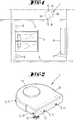
- FIG. 2 shows the soil cultivation device 1 in a perspective view from the outside.
- the soil cultivation device 1 has a plurality of signal output devices 3 which are arranged along the circumference of the housing 10.
- Each signal output device 3 here has a plurality of light sources 11 which are arranged next to one another and one below the other in the manner of an array.
- the light sources 11 of the respective signal output device 3 can be controlled by means of the control and evaluation device in such a way that certain light sources 11 of the respective signal output device 3 emit a light beam, so that the information signal 2 emitted as a whole by the array as a graphic representation, as in a standard LED television arises.
- the light sources 11 can additionally be assigned an optical element which focuses the optical information signal 2 and makes information contained therein readable for a user.
- the soil cultivation device 1 can also additionally have a displaceable carrier for the signal output device 3, so that the direction of emission of the information signal 2 can be varied.
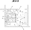
- FIG 3 shows the in Figure 1 Environment shown, in which the soil cultivation device 1 has jammed under an obstacle 9, here a bed.
- the jamming takes place, for example, due to a slatted frame hanging down under the bed, which changes a height difference between the soil cultivation device 1 and the bed.
- the control and evaluation device of the soil cultivation device 1 recognizes a fault condition of the soil cultivation device 1, namely jamming in which the soil cultivation device 1 can no longer move on its own.
- the signal output devices 3 of the soil cultivation device 1 emit information signals 2 to several projection locations 8 in the surroundings, here for example to obstacles 9, such as a closet and room boundaries (walls), or on a floor surface.
- the information signals 2 extend, starting from the soil cultivation device 1, outside the outline of the bed covering the soil cultivation device 1. A user can thereby become aware of the information signal 2.
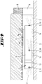
- Figure 4 shows the soil cultivation device 1 below the obstacle 9, namely below the bed, the housing 10 being in contact with the obstacle 9 and being unable to move further under its own drive due to the frictional force that occurs.
- the soil cultivation device 1 thus has a fault condition due to being trapped underneath the obstacle 9.
- the control and evaluation device of the soil cultivation device 1 After the control and evaluation device of the soil cultivation device 1 has recognized the error state, for example because when a driving force is applied to the wheels 14, no movement of the soil cultivation device 1 can be detected by means of the distance measuring device 12, the control and evaluation device causes the signal output devices 3 to send an information signal 2 in each case to project into the environment.
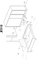
- Figure 5 shows an environment as basically already in Figure 3 is shown, with an information signal 2 projected here onto the floor.
- a projection location 8 is thus created on the floor, on which the information signal 2 is displayed or becomes visible.
- the information signal 2 has a directional indication 5, namely here an arrow, which points in the direction of the current location of the soil cultivation device 1 below the bed.
- such an information signal 2 could also be projected onto an obstacle 9 in the vicinity instead of onto a floor or a floor surface.
- the arrow containing the direction indication 5 results from a projection of a multiplicity of light beams which were emitted by an array of the signal output device 3 containing a plurality of light sources 11.
- different images, in particular directional information can be displayed.
- the information signal 2 has a special color, flashes at certain intervals or the like.
- a projection device comparable to a beamer can also be provided on the floor cleaning device, with automatic focusing preferably also being implemented.
- a laser diode in the range of a visible wavelength in a plurality of lines, preferably horizontally oriented lines, which are then arranged vertically one below the other, an image could be projected correspondingly composed of image lines.
- Figure 6 shows an external device 6 which can be used in combination with the soil cultivation device 1.
- the external device 6 is here, for example, a mobile phone with a display 4 on which one of the soil cultivation device 1 created environment map 7 is displayed.
- An application is installed on the external device 6 which receives messages about error states from the soil cultivation device 1 and offers the user assistance in finding the soil cultivation device 1 and / or in eliminating the error state.
- the soil cultivation device 1 can be used in connection with the external device 6, for example, in such a way that, in the event of an error condition of the soil cultivation device 1, the user first receives a message about the occurrence of the error condition on the external device 6.
- An environment map 7 of the environment of the soil cultivation device 1 is shown on the display 4 of the external device 6, in which, among other things, the current location of the soil cultivation device 1 is shown.
- the application installed on the external device 6 provides a number of options for action that enable a reaction to the error state.
- the user can perform a remote control of the soil cultivation device 1 under the menu item "Manual control" in such a way that he navigates the soil cultivation device 1 out of the clamped position, for example by means of a joystick control.
- further driven elements can be activated to rectify the fault condition, such as rotating cleaning elements 13, in order to free the soil cultivation device 1 under the obstacle 9.
- the user can also select the "Light signal” menu item. This causes an information signal 2 to be output by one or more signal output devices 3 of the soil cultivation device 1.
- the information signal 2 or the directional information 5 contained therein show the user the location of the soil cultivation device 1, so that the user can free the soil cultivation device 1 from the situation. After the user has freed the soil cultivation device 1, the user can on the external device 6 press the "delete errors” button so that a new operation of the soil cultivation device 1 can be started.
- the user To find the soil cultivation device 1 at a location not visible to the user below the obstacle 9, the user follows the directional information 5 contained in the information signal 2, which, starting from the projection location 8, points under the obstacle 9 (bed) jamming the soil cultivation device 1.
Landscapes
- Engineering & Computer Science (AREA)
- Mechanical Engineering (AREA)
- Physics & Mathematics (AREA)
- General Physics & Mathematics (AREA)
- Radar, Positioning & Navigation (AREA)
- Aviation & Aerospace Engineering (AREA)
- Remote Sensing (AREA)
- Automation & Control Theory (AREA)
- Control Of Position, Course, Altitude, Or Attitude Of Moving Bodies (AREA)
- Electric Vacuum Cleaner (AREA)
- Lifting Devices For Agricultural Implements (AREA)
- Guiding Agricultural Machines (AREA)
- Agricultural Machines (AREA)
- Cultivation Receptacles Or Flower-Pots, Or Pots For Seedlings (AREA)
- Optical Communication System (AREA)
- Processing Of Solid Wastes (AREA)
Description
- Die Erfindung betrifft ein Verfahren zum Betrieb eines sich selbsttätig innerhalb einer Umgebung fortbewegenden Bodenbearbeitungsgerätes, wobei eine Steuer- und Auswerteeinrichtung des Bodenbearbeitungsgerätes den Betriebsstatus des Bodenbearbeitungsgerätes überwacht, einen Fehlerzustand des Bodenbearbeitungsgerätes erkennt und im Falle des Auftretens eine Ausgabe eines Fehlerzustands ein Informationssignals veranlasst.
- Des Weiteren betrifft die Erfindung ein sich selbsttätig innerhalb einer Umgebung fortbewegendes Bodenbearbeitungsgerät mit einer Steuer- und Auswerteeinrichtung, welche eingerichtet ist, einen Betriebsstatus des Bodenbearbeitungsgerätes zu überwachen, einen Fehlerzustand des Bodenbearbeitungsgerätes zu erkennen und im Falle des Auftretens eines Fehlerzustands eine Ausgabe eines Informationssignals zu veranlassen.
- Verfahren und Bodenbearbeitungsgeräte der vorgenannten Art sind im Stand der Technik hinreichend bekannt.
- Beispielsweise sind aus der
EP 1 936 463 A2 als Saugroboter und/oder Wischroboter ausgebildete Bodenbearbeitungsgeräte bekannt, die selbsttätig innerhalb einer Umgebung verfahren können. Dazu verfügen diese über eine Navigations- und Selbstlokalisierungseinrichtung, mittels welcher eine Umgebungskarte des Bodenbearbeitungsgerätes erstellt und eine Eigenposition des Bodenbearbeitungsgerätes erkannt werden kann. Die Navigations- und Selbstlokalisierungseinrichtung liest Messdaten aus, welche das Bodenbearbeitungsgerät innerhalb der Umgebung detektiert hat. Beispielsweise kann das Bodenbearbeitungsgerät einen Abstandssensor und einen Odometriesensor aufweisen, welche Abstände zu Hindernissen bzw. zurückgelegte Strecken detektieren. Anhand der erstellten Umgebungskarte sowie aktuell aufgenommener Messdaten kann sich das Bodenbearbeitungsgerät innerhalb der Umgebung orientieren. - Sobald ein Fehlerzustand auftritt, d. h. sich das Bodenbearbeitungsgerät beispielsweise zwischen Hindernissen eingeklemmt hat, einen zu geringen Ladezustand eines Akkumulators aufweist oder auch einen Softwareabsturz beispielsweise der Navigations- und Selbstlokalisierungssoftware feststellt, wird ein Informationssignal an einen Nutzer des Bodenbearbeitungsgerätes ausgegeben, welches den Nutzer über den Fehlerzustand informiert. Das Informationssignal ist üblicherweise eine Tonfolge, die den Nutzer auf das Bodenbearbeitungsgerät aufmerksam macht. Grundsätzlich ist es dem Nutzer anhand dieses akustischen Informationssignals möglich, das Bodenbearbeitungsgerät aufzufinden, wenn sich dieses beispielsweise an einer nicht einsehbaren Stelle, wie beispielsweise unterhalb eines Bettes, Schranks oder dergleichen, befindet.
- Nachteilig bei der Ausgabe von Tonfolgen ist jedoch, dass diese insbesondere bei regelmäßiger Ausgabe störend auf den Nutzer und/oder andere Personen in der Umgebung des Bodenbearbeitungsgerätes wirken können. Auch ist das Auffinden des Bodenbearbeitungsgerätes schwierig, wenn die Tonfolgen in zwar regelmäßigen, aber relativ weit auseinanderliegenden Zeitabschnitten emittiert werden. Nicht zuletzt ist es auch für schwerhörige oder gar gehörlose Personen schwierig, von dem Informationssignal Notiz zu nehmen.
- Ausgehend von dem vorgenannten Stand der Technik ist es daher Aufgabe der Erfindung, ein Bodenbearbeitungsgerät bzw. ein Verfahren zu dessen Betrieb zu schaffen, bei welchem ein Nutzer auf alternative Art und Weise über einen Fehlerzustand informiert wird. Insbesondere ist es Aufgabe, das Bodenbearbeitungsgerät im Falle des Auftretens eines Fehlerzustands leichter auffinden zu können.
- Zur Lösung der vorgenannten Aufgabe wird zunächst ein Verfahren gemäss Anspruch 1 zum Betrieb eines sich selbsttätig fortbewegenden Bodenbearbeitungsgerätes vorgeschlagen, bei welchem eine optische Signalausgabeeinrichtung des Bodenbearbeitungsgerätes das optische Informationssignal emittiert, wobei das optische Informationssignal eine Richtungsangabe darstellende Lichtprojektion erzeugt, wobei die Lichtprojektion auf einem Projektionsort innerhalb der Umgebung des aktuellen Standortes des Bodenbearbeitungsgerätes gerichtet wird, und wobei die Richtungsangabe von dem Projektionsort innerhalb der Umgebung in Richtung des aktuellen Standortes des Bodenbearbeitungsgerätes zeigt.
- Erfindungsgemäß wird ein Fehlerzustand des Bodenbearbeitungsgerätes nun nicht mehr mittels eines akustischen Signals, beispielsweise einer Tonfolge, angezeigt, sondern durch ein optisches Informationssignal, welches von der Signalausgabeeinrichtung an einen Projektionsort innerhalb der Umgebung des Bodenbearbeitungsgerätes projiziert wird. Dadurch können auch schwerhörige oder gehörlose Menschen den aktuellen Standort des Bodenbearbeitungsgerätes besonders einfach erkennen. In dem Fall, dass das Bodenbearbeitungsgerät einen Fehlerzustand aufweist, der beispielsweise eine Weiterfahrt verhindert, kann der Nutzer das optische Informationssignal zurückverfolgen und gelangt somit zu dem Standort des Bodenbearbeitungsgerätes. Das optisehe Informationssignal enthält einen Richtungshinweis, aus welchem der Nutzer eine Information darüber entnehmen kann, in welcher Raumrichtung sich das Bodenbearbeitungsgerät befindet. Beispielsweise kann die Richtungsangabe die Darstellung eines Pfeils beinhalten, welcher ausgehend von dem Projektionsort auf das Bodenbearbeitungsgerät zeigt. Der Nutzer muss somit nur in die von dem Pfeil angezeigte Richtung schauen und kann somit das Bodenbearbeitungsgerät beispielsweise auch unter einem Bett, einem Schrank oder dergleichen auffinden. Der Projektionsort, an welchen das Informationssignal projiziert wird, kann beispielsweise ein Teilbereich einer Bodenfläche sein, eine Front eines Möbelstückes, ein Teilbereich einer Wand oder dergleichen.
- Des Weiteren wird vorgeschlagen, dass das Informationssignal emittiert wird, wenn die Steuer- und Auswerteeinrichtung ein Einklemmen, Behindern und/oder Blockieren des Bodenbearbeitungsgerätes, einen Ladezustand eines Akkumulators unterhalb eines definierten Mindestladezustands und/oder einen fehlerhaften Softwarestatus erkennt. Diese Fehlerzustände behindern oder verhindern eine Weiterfahrt des Bodenbearbeitungsgerätes innerhalb der Umgebung oder zumindest einen optimalen Bearbeitungserfolg des Bodenbearbeitungsgerätes. Zu den Fehlerzuständen gehören zum einen Zustände, in welchen sich das Bodenbearbeitungsgerät unter einem Möbelstück, wie beispielsweise einem Bett, einem Sofa, einer Kommode oder dergleichen festgefahren hat und sich dort aus eigener Kraft nicht mehr lösen kann. Zum anderen kann ein Fehlerzustand eine Situation betreffen, in welcher eine Antriebseinrichtung und/oder ein angetriebenes Rad des Bodenbearbeitungsgerätes blockiert ist und somit eine Fortbewegung verhindert oder zumindest beeinträchtigt. Des Weiteren kann das Bodenbearbeitungsgerät auch durch Hindernisse blockiert werden, welche das Bodenbearbeitungsgerät zwar nicht einklemmen, jedoch in seiner Weiterfahrt behindern, und zwar so, dass das Bodenbearbeitungsgerät nicht selbst aus dieser Situation herausnavigieren kann. Bei diesen Fehlerzuständen kann es erforderlich sein, dass der Nutzer das Bodenbearbeitungsgerät aus der Situation entfernt. Weitere Fehlerzustände sind beispielsweise zu geringe Ladezustände eines Akkumulators des Bodenbearbeitungsgerätes, ein Fehler an einer Betriebssoftware des Bodenbearbeitungsgerätes, welcher eine Fortbewegung und/oder einen ordnungsgemäßen Betrieb des Bodenbearbeitungsgerätes verhindert. Die vorgenannte Aufzählung ist nicht abschließend zu verstehen. Vielmehr sind auch andere Fehlerzustände denkbar, welche ein Eingreifen des Nutzers erfordern oder zumindest empfehlen.
- Des Weiteren kann vorgesehen sein, dass die Signalausgabeeinrichtung das Informationssignal automatisch unmittelbar nach Erkennen eines Fehlerzustands emittiert. Gemäß dieser Ausgestaltung wird unmittelbar dann, wenn die Steuer- und Auswerteeinrichtung des Bodenbearbeitungsgerätes einen Fehlerzustand erkennt, ein Informationssignal von der Signalausgabeeinrichtung ausgesendet. Der Nutzer des Bodenbearbeitungsgerätes muss keine Maßnahmen ergreifen, um ein Informationssignal anzufordern. Vielmehr wird das Informationssignal automatisch in die Umgebung des Bodenbearbeitungsgerätes projiziert, beispielsweise auf einen Fußboden oder an eine Wand oder ein Möbelstück, so dass der Nutzer bei Anwesenheit in dieser Umgebung das Informationssignal bemerkt und auf einen Fehlerzustand des Bodenbearbeitungsgerätes aufmerksam wird. Sodann kann der Nutzer anhand der in dem Informationssignal vorhandenen Richtungsangabe den Standort des Bodenbearbeitungsgerätes ermitteln, das Bodenbearbeitungsgerät auffinden und den Fehlerzustand beheben.
- Alternativ wird vorgeschlagen, dass die Steuer- und Auswerteeinrichtung im Falle eines Fehlerzustands eine Nachricht über den Fehlerzustand an ein in Kommunikationsverbindung mit dem Bodenbearbeitungsgerät stehendes externes Gerät sendet, wobei der Nutzer mittels des externen Gerätes manuell eine Ausgabe eines Informationssignals durch die Signalausgabeeinrichtung des Bodenbearbeitungsgerätes veranlasst. Gemäß dieser Ausgestaltung wird das Informationssignal nicht automatisch emittiert, sobald ein Fehlerzustand des Bodenbearbeitungsgerätes festgestellt wird, sondern nur dann, wenn hierzu auch eine konkrete Anforderung des Nutzers des Bodenbearbeitungsgerätes vorliegt. Zunächst wird der Nutzer bei Auftreten eines Fehlerzustandes mittels einer Nachricht über den Fehlerzustand informiert. Sodann kann er entscheiden, ob ein optisches Informationssignal emittiert werden soll oder nicht. Die Nachricht über den Fehlerzustand wird vorteilhaft an ein mobiles Gerät des Nutzers gesendet, beispielsweise ein Mobiltelefon, ein Tablet-Computer, ein Laptop oder dergleichen. Alternativ kann das Informationssignal jedoch auch an einen lokalen PC, einen entfernten Server oder dergleichen gesendet werden. Die Signalausgabeeinrichtung wird somit nur dann betrieben, wenn der Nutzer dies auch konkret anfordert. Hierdurch kann Energie für unnötige bzw. ungewünschte Lichtprojektionen gespart werden. Das externe Gerät des Nutzers kann eine mit dem Bodenbearbeitungsgerät in Kommunikationsverbindung stehende Applikation aufweisen, welche dem Nutzer einen Fehlerzustand anzeigt. In diesem Zusammenhang kann vorgesehen sein, dass die Nachricht nicht nur eine Information über das Auftreten eines Fehlerzustandes aufweist, sondern zusätzlich weitere Informationen, beispielsweise eine Information über die Art des Fehlerzustandes, einen Vorschlag zum Beheben des Fehlerzustandes, eine Information darüber, seit wann der Fehlerzustand besteht und dergleichen. Im Gegenzug kann der Nutzer mittels der Applikation des externen Gerätes ein Signal an das Bodenbearbeitungsgerät senden, welches die Ausgabe eines Informationssignals veranlasst, so dass die Signalausgabeeinrichtung des Bodenbearbeitungsgerätes erst dann ein Informationssignal in die Umgebung projiziert, wenn der Nutzer für die Suche nach dem Bodenbearbeitungsgerät bereit ist und/oder sich in der Umgebung des Bodenbearbeitungsgerätes befindet.
- Des Weiteren wird vorgeschlagen, dass die Steuer- und Auswerteeinrichtung eine aktuelle Position und Orientierung des Bodenbearbeitungsgerätes anhand einer Umgebungskarte erkennt, Umgebungsinformationen im Bereich des Bodenbearbeitungsgerätes auswertet und das optische Informationssignal an einen Projektionsort der Umgebung projiziert, welcher bezogen auf eine Größe und Richtung der Lichtprojektion frei von Hindernissen ist und/oder aus einer Vogelperspektive einsehbar ist. Diese Ausführung eignet sich insbesondere in Verbindung mit einer Navigations- und Selbstlokalisierungseinrichtung des Bodenbearbeitungsgerätes, welche eine Umgebungskarte der Umgebung des Bodenbearbeitungsgerätes erstellt. Zu diesem Zweck weist das Bodenbearbeitungsgerät beispielsweise einen oder eine Mehrzahl von Sensoren auf, beispielsweise eine Abstandsmesseinrichtung und/oder eine Odometrie-Messeinrichtung. Anhand der gemessenen Abstände zu Raumbegrenzungen, Hindernissen und dergleichen kann eine Umgebungskarte der Umgebung erstellt werden, in welcher die Positionen der Hindernisse und/oder Raumbegrenzungen notiert sind. Auf diese von dem Bodenbearbeitungsgerät selbst erstellte Karte, oder auch eine dem Bodenbearbeitungsgerät von einer anderen Einrichtung übermittelte Umgebungskarte kann die Steuer- und Auswerteeinrichtung zugreifen, um einen geeigneten Projektionsort für die Projektion des optischen Informationssignals zu ermitteln. Hierzu wählt die Steuer- und Auswerteeinrichtung einen Projektionsort aus, welcher frei von Hindernissen ist und/oder für den Nutzer des Bodenbearbeitungsgerätes einsehbar ist. Im Sinne von "frei von Hindernissen" wird des Weiteren eine solche Teilfläche eines Fußbodens, einer Wandfläche, eines Hindernisses oder dergleichen verstanden, welche zum einen groß genug ist, um das optische Informationssignal ausreichend sichtbar zu projizieren, und zum anderen nicht durch andere Hindernisse verdeckt ist, beispielsweise durch einen über einem Teilbereich eines Fußbodens stehenden Tisch, Stuhl oder dergleichen. Der Projektionsort sollte aus der Vogelperspektive einsehbar sein, so dass ein in der Umgebung stehender Nutzer den Projektionsort einsehen kann und somit auch die Richtungsangabe erkennen kann.
- Insbesondere wird vorgeschlagen, dass die Steuer- und Auswerteeinrichtung eine Signalausgabeeinrichtung aus einer Mehrzahl von Signalausgabeeinrichtungen des Bodenbearbeitungsgerätes auswählt, wobei die ausgewählte Signalausgabeeinrichtung nächstgelegen zu dem Projektionsort ist. Das Bodenbearbeitungsgerät weist eine Mehrzahl von Signalausgabeeinrichtungen auf, welche beispielsweise entlang eines Umfangs des Bodenbearbeitungsgerätes angeordnet sind. Die Steuer- und Auswerteeinrichtung wählt aus der Mehrzahl dieser Signalausgabeeinrichtungen eine, oder auch mehrere, Signalausgabeeinrichtungen auf, welche einem optimalen Projektionsort am nächsten liegen bzw. am besten dazu geeignet sind, das Informationssignal an diesen Projektionsort zu projizieren. Die Steuer- und Auswerteeinrichtung hat dazu zum einen Kenntnis über die Positionen und Orientierungen der Signalausgabeeinrichtungen an dem Bodenbearbeitungsgerät, und zum anderen über den aktuellen Standort und die aktuelle Orientierung des Bodenbearbeitungsgerätes innerhalb der Umgebung, so dass zum einen ein geeigneter Projektionsort zur Darstellung des die Richtungsangabe enthaltenen Informationssignals und zum anderen die für die Projektion aktuell am besten geeignete, d. h. positionierte, Signalausgabeeinrichtung ermittelt werden kann.
- Zudem wird vorgeschlagen, dass die Signalausgabeeinrichtung für die Projektion des Informationssignals an den Projektionsort relativ zu einem Gehäuse des Bodenbearbeitungsgerätes verlagert wird und/oder dass das von einer Lichtquelle der Signalausgabeeinrichtung emittierte Informationssignal mittels einer optischen Umlenkeinrichtung umgelenkt wird. Um das Informationssignal an den gewünschten Projektionsort der Umgebung zu projizieren, kann die Signalausgabeeinrichtung beispielsweise auf einem justierbaren Träger an dem Gehäuse des Bodenbearbeitungsgerätes angeordnet sein. Alternativ kann die Signalausgabeeinrichtung bzw. eine Lichtquelle derselben fest mit dem Gehäuse des Bodenbearbeitungsgerätes verbunden sein, wobei die Signalausgebeeinrichtung bzw. die Lichtquelle jedoch mit einer optischen Umlenkeinrichtung kombiniert ist, beispielsweise einem schwenkbaren Spiegel, einem Prisma oder dergleichen. Die Umlenkeinrichtung lenkt das Informationssignal ausgehend von der Lichtquelle der Signalausgabeeinrichtung zu dem gewünschten Projektionsort.
- Neben dem zuvor beschriebenen Verfahren zum Betrieb eines Bodenbearbeitungsgerätes wird mit der Erfindung des Weiteren ein sich selbsttätig innerhalb einer Umgebung fortbewegendes Bodenbearbeitungsgerät mit einer Steuer-und Auswerteeinrichtung gemäss Anspruch 8 vorgeschlagen, wobei die Steuer- und Auswerteeinrichtung eingerichtet ist, einen Betriebsstatus des Bodenbearbeitungsgerätes zu überwachen, einen Fehlerzustand des Bodenbearbeitungsgerätes zu erkennen und im Falle des Auftretens eines Fehlerzustands eine Ausgabe eines Informationssignals zu veranlassen, wobei das Bodenbearbeitungsgerät eine optische Signalausgabeeinrichtung aufweist, welche eingerichtet ist, das optische Informationssignal zu emittieren, wobei das optische Informationssignal eine eine Richtungsangabe darstellende Lichtprojektion erzeugt, wobei die Lichtprojektion auf einen Projektionsort innerhalb der Umgebung des aktuellen Standortes des Bodenbearbeitungsgerätes gerichtet wird, und wobei die Richtungsangabe von einem Projektionsort innerhalb der Umgebung in Richtung des aktuellen Standortes des Bodenbearbeitungsgerätes zeigt.
- Das vorgeschlagene Bodenbearbeitungsgerät ist dadurch ausgebildet, ein zuvor beschriebenes Verfahren auszuführen, bei welchem ein Informationssignal, welches eine Richtungsangabe zu einem Bodenbearbeitungsgerät enthält, an einen Projektionsort projiziert wird. Das Bodenbearbeitungsgerät weist zu diesem Zweck eine optische Signalausgabeeinrichtung auf, welche üblicherweise zumindest eine Lichtquelle aufweist, beispielsweise eine LED oder einen Laser. Die Signalausgabeeinrichtung ist so ausgebildet, dass diese einen Lichtstrahl bzw. Lichtkegel so auf den Projektionsort projiziert, dass die in dem optischen Informationssignal enthaltene Richtungsangabe für einen Nutzer des Bodenbearbeitungsgerätes erkennbar ist. Bei Betrachtung der Lichtprojektion erhält der Benutzer einen Hinweis über die Richtung, in welcher er den aktuellen Standort des Bodenbearbeitungsgerätes auffindet. Die Richtungsangabe ist beispielsweise ein Pfeil, welcher ausgehend von dem Projektionsort in Richtung des Bodenbearbeitungsgerätes zeigt, beispielsweise unter ein Möbelstück, einen von dem Nutzer aktuell nicht einsehbaren Teilbereich der Umgebung oder dergleichen.
- Insbesondere wird vorgeschlagen, dass die Signalausgabeeinrichtung eine Vielzahl von Lichtquellen aufweist und/oder dass die Signalausgabeeinrichtung eine Lichtquelle mit einer veränderlichen Blende aufweist. In dem erstgenannten Fall kann die Signalausgabeeinrichtung beispielsweise ein LED-Array aufweisen, dessen LEDs zur Darstellung einer Richtungsangabe angesteuert werden können. Das durch die Signalausgabeeinrichtung erzeugte Informationssignal kann dann mittels optischer Elemente auf den gewünschten Projektionsort fokussiert, kollimiert und/oder umgelenkt werden, so dass das Informationssignal mit der darin enthaltenen Richtungsangabe für den Nutzer des Bodenbearbeitungsgerätes erkennbar wird. Alternativ kann die Signalausgabeeinrichtung nur eine einzige Lichtquelle aufweisen, welcher eine veränderliche Blende zur Darstellung unterschiedlicher Informationssignale bzw. darin enthaltener Richtungsangaben zugeordnet ist. Die Blende erzeugt beispielsweise den Umriss eines Pfeils innerhalb des auf den Projektionsort projizierten Informationssignals.
- Des Weiteren wird vorgeschlagen, dass die Signalausgabeeinrichtung relativ zu einem Gehäuse des Bodenbearbeitungsgerätes verlagerbar ist, und/oder dass die Signalausgabeeinrichtung eine relativ zu dem Gehäuse verlagerbare optische Umlenkeinrichtung zum Umlenken des emittierten Informationssignals an den Projektionsort aufweist. Die Signalausgabeeinrichtung ist in beiden Fällen ausgebildet, das Informationssignal an unterschiedliche Projektionsorte der Umgebung zu projizieren, indem die Signalausgabeeinrichtung bzw. die Umlenkeinrichtung verlagert, beispielsweise relativ zu dem Gehäuse des Bodenbearbeitungsgerätes verschwenkt, wird. Beispielsweise kann die Signalausgabeeinrichtung auf einem beweglichen Träger des Bodenbearbeitungsgerätes montiert sein, wobei der Träger vorteilhaft motorisch verlagerbar und mittels der Steuer- und Auswerteeinrichtung ansteuerbar ist. Durch die Verlagerung des Trägers ist das Informationssignal an unterschiedliche Projektionsorte projizierbar. Des Weiteren kann eine Lichtquelle der Signalausgabeeinrichtung beispielsweise auch unbeweglich an dem Gehäuse des Bodenbearbeitungsgerätes montiert sein und in Kombination mit einer verlagerbaren Umlenkeinrichtung verwendet werden, welche das Informationssignal, welches von der Lichtquelle emittiert wurde, an einen gewünschten Projektionsort projiziert. Die verlagerbare Umlenkeinrichtung kann beispielsweise ein verlagerbares optisches Element, wie ein Spiegel, ein Prisma oder dergleichen sein.
- Des Weiteren gelten für das erfindungsgemäße Bodenbearbeitungsgerät auch die zuvor in Bezug auf das Verfahren vorgeschlagenen Merkmale und Vorteile. Insbesondere kann das Bodenbearbeitungsgerät eine Navigations- und Selbstlokalisierungseinrichtung aufweisen, welche eine Umgebungskarte der Umgebung erstellt. In der Umgebungskarte kann die Steuer- und Auswerteeinrichtung den optimalen Projektionsort auswählen und gegebenenfalls zusätzlich eine von mehreren möglichen Signalausgabeeinrichtungen, welche geeignet ist, das Informationssignal an den ausgewählten Projektionsort zu projizieren.
- Des Weiteren wird ein Set aus einem Bodenbearbeitungsgerät und einem externen Gerät des Nutzers des Bodenbearbeitungsgerätes vorgeschlagen, wobei das Bodenbearbeitungsgerät und das externe Gerät derart in Kommunikationsverbindung miteinander stehen, dass die Steuer- und Auswerteeinrichtung des Bodenbearbeitungsgerätes eine Nachricht über einen Fehlerzustand an das externe Gerät sendet, wobei die Nachricht auf beispielsweise einem Display des externen Gerätes angezeigt wird und wobei der Nutzer mittels des externen Gerätes manuell eine Ausgabe eines Informationssignals durch die Signalausgabeeinrichtung des Bodenbearbeitungsgerätes veranlassen kann. Das externe Gerät dient somit als Fernsteuerungseinrichtung für das Bodenbearbeitungsgerät. Das Set aus dem Bodenbearbeitungsgerät und dem externen Gerät ist so ausgebildet, dass der Nutzer das Bodenbearbeitungsgerät auffinden und einen Fehlerzustand beheben kann, auch wenn das Bodenbearbeitungsgerät aktuell nicht von dem Standort des Nutzer aus zu sehen ist.
- Im Folgenden wird die Erfindung anhand von Ausführungsbeispielen näher erläutert. Es zeigen:
- Fig. 1
- ein erfindungsgemäßes Bodenbearbeitungsgerät innerhalb einer Umgebung mit einer Mehrzahl von Hindernissen,
- Fig. 2
- eine perspektivische Ansicht des Bodenbearbeitungsgerätes,
- Fig. 3
- die Umgebung gemäß
Figur 1 mit dem Bodenbearbeitungsgerät während des Auftretens eines Fehlerzustandes, - Fig. 4
- eine Seitenansicht des Bodenbearbeitungsgerätes während eines Fehlerzustands,
- Fig. 5
- einen Umgebungsteilbereich der Umgebung mit einer eine Richtungsangabe darstellenden Lichtprojektion,
- Fig. 6
- ein externes Gerät, auf welchem eine Umgebungskarte während eines Fehlerzustandes des Bodenbearbeitungsgerätes angezeigt ist.
-
Figur 1 zeigt eine Umgebung, welche hier einen Teilbereich einer Wohnung darstellt. Innerhalb der Umgebung befindet sich ein Bodenbearbeitungsgerät 1, welches hier beispielsweise als sich selbsttätig fortbewegender Saugroboter ausgebildet ist. Das Bodenbearbeitungsgerät 1 verfügt über zwei Reinigungselemente 13, nämlich eine unterhalb eines Gehäuses 10 des Bodenbearbeitungsgerätes 1 angeordnete Borstenwalze und eine an einem Eckbereich des Gehäuses 10 angeordnete Seitenbürste, mittels welcher insbesondere Übergangsbereiche zwischen einem Fußboden und einer Wand gereinigt werden können. Das Bodenbearbeitungsgerät 1 verfügt über Räder 14, welche motorisch angetrieben sind und somit zur Fortbewegung des Bodenbearbeitungsgerätes 1 innerhalb der Umgebung dienen. - Die Umgebung weist eine Vielzahl von Hindernissen 9 auf, welche hier beispielsweise Raumbegrenzungen, ein Schrank, ein Bett und zwei Nachttische sind. Die Hindernisse 9 sind zumindest zum Teil so ausgestaltet, dass das Bodenbearbeitungsgerät 1 bei einer Verfahrbewegung unter diese gelangen kann.
- Das Bodenbearbeitungsgerät 1 weist eine Navigations- und Selbstlokalisierungseinrichtung (nicht dargestellt) auf, welche Daten einer Abstandsmesseinrichtung 12 des Bodenbearbeitungsgerätes 1 ausliest, die hier beispielsweise eine Triangulationsmesseinrichtung umfasst. Mittels der Abstandsmesseinrichtung 12 werden Abstände zu den Hindernissen 9 ermittelt und zu einer Umgebungskarte 7 (siehe
Figur 6 ) kombiniert. In der Umgebungskarte 7 sind die Hindernisse 9 und auch der aktuelle Standort des Bodenbearbeitungsgerätes 1 enthalten. Während der Fortbewegung des Bodenbearbeitungsgerätes 1 wird die Umgebungskarte 7 stetig aktualisiert. Die Navigations- und Selbstlokalisierungseinrichtung steht in Kommunikationsverbindung mit einer Steuer- und Auswerteeinrichtung des Bodenbearbeitungsgerätes 1, welche den Betriebsstatus des Bodenbearbeitungsgerätes 1 überwacht, einen Fehlerzustand des Bodenbearbeitungsgerätes 1 erkennen kann und im Falle des Auftretens eines Fehlerzustands eine Ausgabe eines Informationssignals 2 veranlassen kann, durch welches ein Nutzer des Bodenbearbeitungsgerätes 1 über den Fehlerzustand informiert wird. -
Figur 2 zeigt das Bodenbearbeitungsgerät 1 in einer perspektivischen Ansicht von außen. Das Bodenbearbeitungsgerät 1 weist eine Mehrzahl von Signalausgabeeinrichtungen 3 auf, welche entlang des Umfangs des Gehäuses 10 angeordnet sind. Jede Signalausgabeeinrichtung 3 weist hier eine Mehrzahl von Lichtquellen 11 auf, welche nach der Art eines Arrays nebeneinander und untereinander angeordnet sind. Die Lichtquellen 11 der jeweiligen Signalausgabeeinrichtung 3 können mittels der Steuer- und Auswerteeinrichtung so gesteuert werden, dass bestimmte Lichtquellen 11 der jeweiligen Signalausgabeeinrichtung 3 einen Lichtstrahl emittieren, so dass das von dem Array insgesamt emittierte Informationssignal 2 wie bei einem handelsüblichen LED-Fernseher als bildliche Darstellung entsteht. Den Lichtquellen 11 kann dabei zusätzlich ein optisches Element zugeordnet sein, welches das optische Informationssignal 2 fokussiert und eine darin enthaltene Information für einen Nutzer lesbar macht. Obwohl dies inFigur 2 nicht dargestellt ist, kann das Bodenbearbeitungsgerät 1 auch zusätzlich einen verlagerbaren Träger für die Signalausgabeeinrichtung 3 aufweisen, so dass die Emissionsrichtung des Informationssignals 2 variiert werden kann. -
Figur 3 zeigt die inFigur 1 dargestellte Umgebung, in welcher sich das Bodenbearbeitungsgerät 1 unter einem Hindernis 9, hier einem Bett, eingeklemmt hat. Das Einklemmen erfolgt beispielsweise aufgrund eines unter dem Bett herunterhängenden Lattenrostes, welches einen Höhenunterschied zwischen dem Bodenbearbeitungsgerät 1 und dem Bett ändert. In dieser Situation erkennt die Steuer- und Auswerteeinrichtung des Bodenbearbeitungsgerätes 1 einen Fehlerzustand des Bodenbearbeitungsgerätes 1, nämlich ein Einklemmen, bei welchem eine Fortbewegung des Bodenbearbeitungsgerätes 1 aus eigenem Antrieb nicht mehr möglich ist. Um einen Nutzer des Bodenbearbeitungsgerätes 1 über diesen Fehler zu informieren und dem Nutzer gleichzeitig einen Hinweis auf den aktuellen Standort des Bodenbearbeitungsgerätes 1 zu geben, emittieren die Signalausgabeeinrichtungen 3 des Bodenbearbeitungsgerätes 1 Informationssignale 2 an mehrere Projektionsorte 8 der Umgebung, hier beispielsweise an Hindernisse 9, wie einen Schrank und Raumbegrenzungen (Wänden), oder auf eine Bodenfläche. Die Informationssignale 2 erstrecken sich ausgehend von dem Bodenbearbeitungsgerät 1 außerhalb des Umrisses des das Bodenbearbeitungsgerät 1 verdeckenden Bettes. Dadurch kann ein Nutzer auf das Informationssignal 2 aufmerksam werden. -
Figur 4 zeigt das Bodenbearbeitungsgerät 1 unterhalb des Hindernisses 9, nämlich unterhalb des Bettes, wobei das Gehäuse 10 in Kontakt mit dem Hindernis 9 steht und aufgrund der auftretenden Reibkraft nicht aus eigener Antriebskraft weiter verfahren kann. Das Bodenbearbeitungsgerät 1 weist somit einen Fehlerzustand durch Einklemmen unterhalb des Hindernisses 9 auf. Nachdem die Steuer- und Auswerteeinrichtung des Bodenbearbeitungsgerätes 1 den Fehlerzustand erkannt hat, beispielsweise weil bei Aufbringen einer Antriebskraft auf die Räder 14 keine Fortbewegung des Bodenbearbeitungsgerätes 1 mittels der Abstandsmesseinrichtung 12 festzustellen ist, veranlasst die Steuer- und Auswerteeinrichtung die Signalausgabeeinrichtungen 3, jeweils ein Informationssignal 2 in die Umgebung zu projizieren. -
Figur 5 zeigt eine Umgebung wie grundsätzlich schon inFigur 3 dargestellt ist, mit einem hier auf den Boden projizierten Informationssignal 2. Auf dem Boden ist damit ein Projektionsort 8 geschaffen, auf welchem das Informationssignal 2 dargestellt ist bzw. sichtbar wird. Das Informationssignal 2 weist eine Richtungsangabe 5, nämlich hier einen Pfeil, auf, welcher in Richtung des aktuellen Standortes des Bodenbearbeitungsgerätes 1 unterhalb des Bettes weist. Alternativ könnte ein solches Informationssignal 2 anstatt auf einen Boden oder eine Bodenfläche auch auf ein Hindernis 9 in der Umgebung projiziert werden. Der die Richtungsangabe 5 enthaltende Pfeil ergibt sich aufgrund einer Projektion einer Vielzahl von Lichtstrahlen, die von einem mehrere Lichtquellen 11 enthaltenen Array der Signalausgabeeinrichtung 3 emittiert wurden. Je nach der Aktivität bzw. Nichtaktivität einzelner Lichtquellen 11 innerhalb des Arrays können unterschiedliche Bilder, insbesondere Richtungsangaben, dargestellt werden. Des Weiteren kann auch vorgesehen sein, dass das Informationssignal 2 eine besondere Farbe aufweist, in bestimmten Abständen blinkt oder dergleichen. - Bezüglich insbesondere eine Projektion auf ein Hindernis 9, also auf eine vertikale oder im Wesentlichen vertikale Fläche, kann auch eine einem Beamer vergleichbare Projektionseinrichtung an dem Bodenreinigungsgerät vorgesehen sein, wobei bevorzugt auch eine automatische Fokussierung verwirklicht ist. Alternativ könnte auch mittels einer Laserdiode im Bereich einer sichtbaren Wellenlänge in einer Vielzahl von Linien, bevorzugt horizontal orientierten Linien, die dann vertikal untereinander angeordnet sind, ein Bild entsprechend aus Bildzeilen zusammengesetzt projiziert werden.
-
Figur 6 zeigt ein externes Gerät 6, welches in Kombination mit dem Bodenbearbeitungsgerät 1 Verwendung finden kann. Das externe Gerät 6 ist hier beispielsweise ein Mobiltelefon mit einem Display 4, auf welchem eine von dem Bodenbearbeitungsgerät 1 erstellte Umgebungskarte 7 angezeigt wird. Auf dem externen Gerät 6 ist eine Applikation installiert, welche Nachrichten über Fehlerzustände von dem Bodenbearbeitungsgerät 1 empfängt und dem Nutzer eine Hilfestellung bei dem Auffinden des Bodenbearbeitungsgerätes 1 und/ oder einer Behebung des Fehlerzustandes bietet. - Das Bodenbearbeitungsgerät 1 kann in Verbindung mit dem externen Gerät 6 beispielsweise so verwendet werden, dass der Nutzer im Falle eines Fehlerzustandes des Bodenbearbeitungsgerätes 1 zunächst eine Nachricht über das Auftreten des Fehlerzustandes auf dem externen Gerät 6 erhält. Auf dem Display 4 des externen Gerätes 6 wird eine Umgebungskarte 7 der Umgebung des Bodenbearbeitungsgerätes 1 dargestellt, in welcher unter anderem der aktuelle Standort des Bodenbearbeitungsgerätes 1 dargestellt ist. Des Weiteren stellt die auf dem externen Gerät 6 installierte Applikation mehrere Handlungsoptionen zur Auswahl, welche eine Reaktion auf den Fehlerzustand ermöglichen. Zum einen kann der Nutzer unter dem Menüpunkt "Manuelle Steuerung" eine Fernbedienung des Bodenbearbeitungsgerätes 1 derart ausführen, dass er das Bodenbearbeitungsgerät 1 beispielsweise mittels einer Joystick-Steuerung aus der eingeklemmten Stellung heraus navigiert. Gegebenenfalls können zur Behebung des Fehlerzustandes weitere angetriebene Elemente aktiviert werden, wie beispielsweise rotierende Reinigungselemente 13, um das Bodenbearbeitungsgerät 1 unter dem Hindernis 9 zu befreien. Des Weiteren kann der Nutzer den Menüpunkt "Lichtsignal" wählen. Dadurch wird eine Ausgabe eines Informationssignals 2 durch eine oder mehrere Signalausgabeeinrichtungen 3 des Bodenbearbeitungsgerätes 1 veranlasst. Das Informationssignal 2 bzw. die darin enthaltene Richtungsangabe 5 zeigen dem Nutzer den Standort des Bodenbearbeitungsgerätes 1 an, so dass der Nutzer das Bodenbearbeitungsgerät 1 aus der Situation befreien kann. Nachdem der Nutzer das Bodenbearbeitungsgerät 1 befreit hat, kann der Nutzer auf dem externen Gerät 6 die Taste "Fehler löschen" betätigen, so dass ein erneuter Betrieb des Bodenbearbeitungsgerätes 1 gestartet werden kann.
- Für das Auffinden des Bodenbearbeitungsgerätes 1 an einem nicht für den Nutzer einsehbaren Standort unterhalb des Hindernisses 9 folgt der Nutzer der in dem Informationssignal 2 enthaltenen Richtungsangabe 5, welche ausgehend von dem Projektionsort 8 unter das das Bodenbearbeitungsgerät 1 einklemmende Hindernis 9 (Bett) weist.
-
- 1
- Bodenbearbeitungsgerät
- 2
- Informationssignal
- 3
- Signalausgabeeinrichtung
- 4
- Display
- 5
- Richtungsangabe
- 6
- Externes Gerät
- 7
- Umgebungskarte
- 8
- Projektionsort
- 9
- Hindernis
- 10
- Gehäuse
- 11
- Lichtquelle
- 12
- Abstandsmesseinrichtung
- 13
- Reinigungselement
- 14
- Rad
Claims (10)
- Verfahren zum Betrieb eines sich selbsttätig innerhalb einer Umgebung fortbewegenden Bodenbearbeitungsgerätes (1), wobei eine Steuer- und Auswerteeinrichtung des Bodenbearbeitungsgerätes (1) den Betriebsstatus des Bodenbearbeitungsgerätes (1) überwacht, einen Fehlerzustand des Bodenbearbeitungsgerätes (1) erkennt und im Falle des Auftretens eines Fehlerzustands eine Ausgabe eines optischen Informationssignals (2) veranlasst, dadurch gekennzeichnet, dass eine optische Signalausgabeeinrichtung (3) des Bodenbearbeitungsgerätes (1) das optische Informationssignal (2) emittiert, wobei das optische Informationssignal (2) eine eine Richtungsangabe (5) darstellende Lichtprojektion erzeugt, wobei die Lichtprojektion auf einen Projektionsort (8) innerhalb der Umgebung des aktuellen Standortes des Bodenbearbeitungsgerätes (1) gerichtet wird, und wobei die Richtungsangabe (5) von dem Projektionsort (8) innerhalb der Umgebung in Richtung des aktuellen Standortes des Bodenbearbeitungsgerätes (1) zeigt.
- Verfahren nach Anspruch 1, dadurch gekennzeichnet, dass das optische Informationssignal (2) emittiert wird, wenn die Steuer- und Auswerteeinrichtung ein Einklemmen, Behindern und/oder Blockieren des Bodenbearbeitungsgerätes (1), einen Ladezustand eines Akkumulators unterhalb eines definierten Mindestladezustands und/oder einen fehlerhaften Softwarestatus erkennt.
- Verfahren nach Anspruch 1 oder 2, dadurch gekennzeichnet, dass die Signalausgabeeinrichtung (3) das optische Informationssignal (2) automatisch unmittelbar nach Erkennen eines Fehlerzustands emittiert.
- Verfahren nach Anspruch 1 oder 2, dadurch gekennzeichnet, dass die Steuer- und Auswerteeinrichtung im Falle eines Fehlerzustands eine Nachricht über den Fehlerzustand an ein in Kommunikationsverbindung mit dem Bodenbearbeitungsgerät (1) stehendes externes Gerät (6) sendet, wobei der Nutzer mittels des externen Gerätes (6) manuell eine Ausgabe eines Informationssignals (2) durch die Signalausgabeeinrichtung (3) des Bodenbearbeitungsgerätes (1) veranlasst.
- Verfahren nach einem der vorhergehenden Ansprüche, dadurch gekennzeichnet, dass die Steuer- und Auswerteeinrichtung eine aktuelle Position und Orientierung des Bodenbearbeitungsgerätes (1) anhand einer Umgebungskarte (7) erkennt, Umgebungsinformationen im Bereich des Bodenbearbeitungsgerätes (1) auswertet und das optische Informationssignal (2) an einen Projektionsort (8) der Umgebung projiziert, welcher bezogen auf eine Größe und Richtung der Lichtprojektion frei von Hindernissen (9) ist und/oder aus einer Vogelperspektive einsehbar ist.
- Verfahren nach Anspruch 5, dadurch gekennzeichnet, dass die Steuer-und Auswerteeinrichtung eine Signalausgabeeinrichtung (3) aus einer Mehrzahl von-Signalausgabeeinrichtungen (3) des Bodenbearbeitungsgerätes (1) auswählt, wobei die ausgewählte Signalausgabeeinrichtung (3) nächstgelegen zu dem Projektionsort (8) ist.
- Verfahren nach einem der vorhergehenden Ansprüche, dadurch gekennzeichnet, dass die Signalausgabeeinrichtung (3) für die Projektion des optischen Informationssignals (2) an den Projektionsort (8) relativ zu einem Gehäuse (10) des Bodenbearbeitungsgerätes (1) verlagert wird und/oder dass das von einer Lichtquelle (11) der Signalausgabeeinrichtung (3) emittierte optische Informationssignal (2) mittels einer optischen Umlenkeinrichtung umgelenkt wird.
- Sich selbsttätig innerhalb einer Umgebung fortbewegendes Bodenbearbeitungsgerät (1) mit einer Steuer- und Auswerteeinrichtung, welche eingerichtet ist, einen Betriebsstatus des Bodenbearbeitungsgerätes (1) zu überwachen, einen Fehlerzustand des Bodenbearbeitungsgerätes (1) zu erkennen und im Falle des Auftretens eines Fehlerzustands eine Ausgabe eines optischen Informationssignals (2) zu veranlassen, dadurch gekennzeichnet, dass das Bodenbearbeitungsgerät (1) eine optische Signalausgabeeinrichtung (3) aufweist, welche eingerichtet ist, das optische Informationssignal (2) zu emittieren, wobei das optische Informationssignal (2) eine eine Richtungsangabe (5) darstellende Lichtprojektion erzeugt, wobei die Lichtprojektion auf einen Projektionsort (8) innerhalb der Umgebung des aktuellen Standortes des Bodenbearbeitungsgerätes (1) gerichtet wird, und wobei die Richtungsangabe (5) von dem Projektionsort (8) innerhalb der Umgebung in Richtung des aktuellen Standortes des Bodenbearbeitungsgerätes (1) zeigt.
- Bodenbearbeitungsgerät (1) nach Anspruch 8, dadurch gekennzeichnet, dass die Signalausgabeeinrichtung (3) eine Vielzahl von Lichtquellen (11) und/oder eine Lichtquelle (11) mit einer veränderlichen Blende aufweist.
- Bodenbearbeitungsgerät (1) nach Anspruch 8 oder 9, dadurch gekennzeichnet, dass die Signalausgabeeinrichtung (3) relativ zu einem Gehäuse (10) des Bodenbearbeitungsgerätes (1) verlagerbar ist, und/oder dass die Signalausgabeeinrichtung (3) eine relativ zu dem Gehäuse (10) verlagerbare optische Umlenkeinrichtung zum Umlenken des emittierten optischen Informationssignals (2) an den Projektionsort (8) aufweist.
Applications Claiming Priority (1)
| Application Number | Priority Date | Filing Date | Title |
|---|---|---|---|
| DE102017105540.1A DE102017105540A1 (de) | 2017-03-15 | 2017-03-15 | Verfahren zum Betrieb eines sich selbsttätig fortbewegenden Bodenbearbeitungsgerätes |
Publications (2)
| Publication Number | Publication Date |
|---|---|
| EP3376331A1 EP3376331A1 (de) | 2018-09-19 |
| EP3376331B1 true EP3376331B1 (de) | 2021-04-28 |
Family
ID=61569063
Family Applications (1)
| Application Number | Title | Priority Date | Filing Date |
|---|---|---|---|
| EP18159437.5A Active EP3376331B1 (de) | 2017-03-15 | 2018-03-01 | Verfahren zum betrieb eines sich selbsttätig fortbewegenden bodenbearbeitungsgerätes |
Country Status (8)
| Country | Link |
|---|---|
| US (1) | US11019973B2 (de) |
| EP (1) | EP3376331B1 (de) |
| JP (1) | JP2018156644A (de) |
| CN (1) | CN108618709B (de) |
| DE (1) | DE102017105540A1 (de) |
| ES (1) | ES2876440T3 (de) |
| SG (1) | SG10201801616XA (de) |
| TW (1) | TW201838579A (de) |
Families Citing this family (4)
| Publication number | Priority date | Publication date | Assignee | Title |
|---|---|---|---|---|
| DE102020211430B4 (de) | 2020-09-11 | 2022-12-22 | BSH Hausgeräte GmbH | Bodenreinigungssystem |
| JP7574820B2 (ja) | 2022-03-17 | 2024-10-29 | トヨタ自動車株式会社 | 規制領域管理システム、移動体管理システム、規制領域管理方法、プログラム |
| CA3205439A1 (en) * | 2022-06-29 | 2023-12-29 | Avidbots Corp | Incident notification system for a semi-autonomous cleaning device |
| JP2026052788A (ja) | 2024-09-12 | 2026-03-25 | 横河電機株式会社 | 情報処理装置、情報処理方法および情報処理プログラム |
Family Cites Families (14)
| Publication number | Priority date | Publication date | Assignee | Title |
|---|---|---|---|---|
| KR100767120B1 (ko) * | 2006-11-28 | 2007-10-17 | 삼성광주전자 주식회사 | 로봇청소기 및 그 제어방법 |
| US20090013922A1 (en) * | 2007-07-13 | 2009-01-15 | Yung-Fa Lin | Automobile projected light for life safety |
| US8733939B2 (en) * | 2012-07-26 | 2014-05-27 | Cloudcar, Inc. | Vehicle content projection |
| DE102013215409A1 (de) * | 2013-08-06 | 2015-02-12 | Robert Bosch Gmbh | Projektionseinheit für eine selbsttätig mobile Plattform, Transportroboter und Verfahren zum Betrieb einer selbsttätig mobilen Plattform |
| EP3035834B1 (de) * | 2013-08-22 | 2019-01-09 | Carr, Jr., George Allen | System und verfahren zur beleuchtung eines objekts |
| CN204120949U (zh) * | 2014-07-26 | 2015-01-28 | 陈元广 | 一种带故障指示功能的紫外吸尘器 |
| DE102014011915A1 (de) * | 2014-08-12 | 2016-02-18 | Man Truck & Bus Ag | Verfahren zur Warnung von Verkehrsteilnehmern vor möglichen Gefahrenbereichen, die durch ein Fahrzeug entstehen, das ein Fahrmanöver ausführt oder ausführen will |
| US9902061B1 (en) * | 2014-08-25 | 2018-02-27 | X Development Llc | Robot to human feedback |
| DE102015107598A1 (de) * | 2015-05-13 | 2016-11-17 | Vorwerk & Co. Interholding Gmbh | Verfahren zum Betrieb eines selbsttätig verfahrbaren Reinigungsgerätes |
| US9663025B2 (en) * | 2015-09-18 | 2017-05-30 | Clearpath Robotics, Inc. | Lighting control system and method for autonomous vehicles |
| US10265859B2 (en) * | 2016-02-09 | 2019-04-23 | Cobalt Robotics Inc. | Mobile robot with removable fabric panels |
| US10630958B2 (en) * | 2016-07-01 | 2020-04-21 | Intel Corporation | Technologies for automated projector placement for projected computing interactions |
| US10272828B2 (en) * | 2016-08-16 | 2019-04-30 | Irobot Corporation | Light indicator system for an autonomous mobile robot |
| JP2020509500A (ja) * | 2017-03-02 | 2020-03-26 | ロブアート ゲーエムベーハーROBART GmbH | 自律移動ロボットの制御方法 |
-
2017
- 2017-03-15 DE DE102017105540.1A patent/DE102017105540A1/de not_active Withdrawn
-
2018
- 2018-02-28 SG SG10201801616XA patent/SG10201801616XA/en unknown
- 2018-03-01 EP EP18159437.5A patent/EP3376331B1/de active Active
- 2018-03-01 ES ES18159437T patent/ES2876440T3/es active Active
- 2018-03-05 JP JP2018038251A patent/JP2018156644A/ja active Pending
- 2018-03-12 US US15/918,062 patent/US11019973B2/en active Active
- 2018-03-13 CN CN201810203898.0A patent/CN108618709B/zh active Active
- 2018-03-15 TW TW107108864A patent/TW201838579A/zh unknown
Non-Patent Citations (1)
| Title |
|---|
| None * |
Also Published As
| Publication number | Publication date |
|---|---|
| CN108618709B (zh) | 2021-06-22 |
| ES2876440T3 (es) | 2021-11-12 |
| US20180263451A1 (en) | 2018-09-20 |
| US11019973B2 (en) | 2021-06-01 |
| TW201838579A (zh) | 2018-11-01 |
| CN108618709A (zh) | 2018-10-09 |
| SG10201801616XA (en) | 2018-10-30 |
| EP3376331A1 (de) | 2018-09-19 |
| DE102017105540A1 (de) | 2018-09-20 |
| JP2018156644A (ja) | 2018-10-04 |
Similar Documents
| Publication | Publication Date | Title |
|---|---|---|
| EP3376331B1 (de) | Verfahren zum betrieb eines sich selbsttätig fortbewegenden bodenbearbeitungsgerätes | |
| EP3408719B1 (de) | Verfahren zum erstellen einer umgebungskarte für ein selbsttätig verfahrbares bearbeitungsgerät | |
| EP3415065B1 (de) | System mit mindestens zwei reinigungsgeräten | |
| DE102015206158B4 (de) | Mobiles C-Bogensystem | |
| EP3189384B1 (de) | Vorrichtung zum erfassen geleisteter reinigungsarbeiten | |
| EP3441840B1 (de) | Verfahren zum betrieb eines sich selbsttätig fortbewegenden reinigungsgerätes | |
| EP2741483B1 (de) | Verfahrbares Reinigungsgerät sowie Verfahren zum Betreiben eines solchen | |
| EP2755101B1 (de) | Selbstfahrender Roboter und Verfahren zur Abstandsbestimmung bei einem selbstfahrenden Roboter | |
| EP3733037B1 (de) | System aus einem manuell geführten bodenbearbeitungsgerät, einem ausschliesslich automatisch betriebenen bodenbearbeitungsgerät und einer recheneinrichtung | |
| EP3379990B1 (de) | Bodenreinigungssystem und verfahren zum reinigen einer bodenfläche | |
| EP3376328B1 (de) | Verfahren zum automatischen betrieb eines sich selbsttätig fortbewegenden bodenbearbeitungsgerätes | |
| EP2680097B1 (de) | Selbstfahrendes Reinigungsgerät und Verfahren zur Bedienung eines selbstfahrenden Reinigungsgeräts | |
| EP3355147A1 (de) | Verfahren zum betrieb eines sich selbsttätig fortbewegenden fahrzeugs | |
| EP3708058B1 (de) | Bodenbearbeitungsgerät und system aus einem bodenbearbeitungsgerät und einem externen endgerät | |
| DE102018116065A1 (de) | Verfahren zum Betrieb eines sich selbsttätig fortbewegenden Servicegerätes | |
| EP3995065B1 (de) | Sich selbsttätig fortbewegendes reinigungsgerät | |
| WO2018115153A1 (de) | Verfahren zur navigation und selbstlokalisierung eines sich autonom fortbewegenden bearbeitungsgerätes | |
| EP3524114A1 (de) | Reinigungsroboter und verfahren zur steuerung eines reinigungsroboters | |
| DE202017104980U1 (de) | Sich selbsttätig fortbewegendes Bodenbearbeitungsgerät | |
| DE102017118554A1 (de) | Staubsauger mit Positionsbestimmung sowie Verfahren zum Betreiben eines Staubsaugers | |
| EP3428759A1 (de) | Verfahren zum betrieb eines sich selbsttätig fortbewegenden servicegerätes | |
| EP4113238B1 (de) | Verfahren zur autonomen bearbeitung von bodenflächen | |
| EP4410166B1 (de) | Verfahren zum betrieb eines mobilen, selbstfahrenden geräts | |
| EP4116788B1 (de) | Sich selbsttätig fortbewegendes bodenbearbeitungsgerät | |
| EP3254593B1 (de) | Sensoranordnung für die optimierte navigation einer mobilen robotereinheit |
Legal Events
| Date | Code | Title | Description |
|---|---|---|---|
| PUAI | Public reference made under article 153(3) epc to a published international application that has entered the european phase |
Free format text: ORIGINAL CODE: 0009012 |
|
| STAA | Information on the status of an ep patent application or granted ep patent |
Free format text: STATUS: THE APPLICATION HAS BEEN PUBLISHED |
|
| AK | Designated contracting states |
Kind code of ref document: A1 Designated state(s): AL AT BE BG CH CY CZ DE DK EE ES FI FR GB GR HR HU IE IS IT LI LT LU LV MC MK MT NL NO PL PT RO RS SE SI SK SM TR |
|
| AX | Request for extension of the european patent |
Extension state: BA ME |
|
| STAA | Information on the status of an ep patent application or granted ep patent |
Free format text: STATUS: REQUEST FOR EXAMINATION WAS MADE |
|
| 17P | Request for examination filed |
Effective date: 20181214 |
|
| RBV | Designated contracting states (corrected) |
Designated state(s): AL AT BE BG CH CY CZ DE DK EE ES FI FR GB GR HR HU IE IS IT LI LT LU LV MC MK MT NL NO PL PT RO RS SE SI SK SM TR |
|
| STAA | Information on the status of an ep patent application or granted ep patent |
Free format text: STATUS: EXAMINATION IS IN PROGRESS |
|
| 17Q | First examination report despatched |
Effective date: 20191024 |
|
| GRAP | Despatch of communication of intention to grant a patent |
Free format text: ORIGINAL CODE: EPIDOSNIGR1 |
|
| STAA | Information on the status of an ep patent application or granted ep patent |
Free format text: STATUS: GRANT OF PATENT IS INTENDED |
|
| INTG | Intention to grant announced |
Effective date: 20201106 |
|
| GRAS | Grant fee paid |
Free format text: ORIGINAL CODE: EPIDOSNIGR3 |
|
| GRAA | (expected) grant |
Free format text: ORIGINAL CODE: 0009210 |
|
| STAA | Information on the status of an ep patent application or granted ep patent |
Free format text: STATUS: THE PATENT HAS BEEN GRANTED |
|
| AK | Designated contracting states |
Kind code of ref document: B1 Designated state(s): AL AT BE BG CH CY CZ DE DK EE ES FI FR GB GR HR HU IE IS IT LI LT LU LV MC MK MT NL NO PL PT RO RS SE SI SK SM TR |
|
| REG | Reference to a national code |
Ref country code: GB Ref legal event code: FG4D Free format text: NOT ENGLISH |
|
| REG | Reference to a national code |
Ref country code: CH Ref legal event code: EP |
|
| REG | Reference to a national code |
Ref country code: AT Ref legal event code: REF Ref document number: 1387798 Country of ref document: AT Kind code of ref document: T Effective date: 20210515 |
|
| REG | Reference to a national code |
Ref country code: DE Ref legal event code: R096 Ref document number: 502018004961 Country of ref document: DE |
|
| REG | Reference to a national code |
Ref country code: IE Ref legal event code: FG4D Free format text: LANGUAGE OF EP DOCUMENT: GERMAN |
|
| REG | Reference to a national code |
Ref country code: LT Ref legal event code: MG9D |
|
| PG25 | Lapsed in a contracting state [announced via postgrant information from national office to epo] |
Ref country code: NL Free format text: LAPSE BECAUSE OF FAILURE TO SUBMIT A TRANSLATION OF THE DESCRIPTION OR TO PAY THE FEE WITHIN THE PRESCRIBED TIME-LIMIT Effective date: 20210428 Ref country code: HR Free format text: LAPSE BECAUSE OF FAILURE TO SUBMIT A TRANSLATION OF THE DESCRIPTION OR TO PAY THE FEE WITHIN THE PRESCRIBED TIME-LIMIT Effective date: 20210428 Ref country code: BG Free format text: LAPSE BECAUSE OF FAILURE TO SUBMIT A TRANSLATION OF THE DESCRIPTION OR TO PAY THE FEE WITHIN THE PRESCRIBED TIME-LIMIT Effective date: 20210728 Ref country code: FI Free format text: LAPSE BECAUSE OF FAILURE TO SUBMIT A TRANSLATION OF THE DESCRIPTION OR TO PAY THE FEE WITHIN THE PRESCRIBED TIME-LIMIT Effective date: 20210428 Ref country code: LT Free format text: LAPSE BECAUSE OF FAILURE TO SUBMIT A TRANSLATION OF THE DESCRIPTION OR TO PAY THE FEE WITHIN THE PRESCRIBED TIME-LIMIT Effective date: 20210428 |
|
| REG | Reference to a national code |
Ref country code: ES Ref legal event code: FG2A Ref document number: 2876440 Country of ref document: ES Kind code of ref document: T3 Effective date: 20211112 |
|
| PG25 | Lapsed in a contracting state [announced via postgrant information from national office to epo] |
Ref country code: IS Free format text: LAPSE BECAUSE OF FAILURE TO SUBMIT A TRANSLATION OF THE DESCRIPTION OR TO PAY THE FEE WITHIN THE PRESCRIBED TIME-LIMIT Effective date: 20210828 Ref country code: GR Free format text: LAPSE BECAUSE OF FAILURE TO SUBMIT A TRANSLATION OF THE DESCRIPTION OR TO PAY THE FEE WITHIN THE PRESCRIBED TIME-LIMIT Effective date: 20210729 Ref country code: PT Free format text: LAPSE BECAUSE OF FAILURE TO SUBMIT A TRANSLATION OF THE DESCRIPTION OR TO PAY THE FEE WITHIN THE PRESCRIBED TIME-LIMIT Effective date: 20210830 Ref country code: PL Free format text: LAPSE BECAUSE OF FAILURE TO SUBMIT A TRANSLATION OF THE DESCRIPTION OR TO PAY THE FEE WITHIN THE PRESCRIBED TIME-LIMIT Effective date: 20210428 Ref country code: NO Free format text: LAPSE BECAUSE OF FAILURE TO SUBMIT A TRANSLATION OF THE DESCRIPTION OR TO PAY THE FEE WITHIN THE PRESCRIBED TIME-LIMIT Effective date: 20210728 Ref country code: LV Free format text: LAPSE BECAUSE OF FAILURE TO SUBMIT A TRANSLATION OF THE DESCRIPTION OR TO PAY THE FEE WITHIN THE PRESCRIBED TIME-LIMIT Effective date: 20210428 Ref country code: SE Free format text: LAPSE BECAUSE OF FAILURE TO SUBMIT A TRANSLATION OF THE DESCRIPTION OR TO PAY THE FEE WITHIN THE PRESCRIBED TIME-LIMIT Effective date: 20210428 Ref country code: RS Free format text: LAPSE BECAUSE OF FAILURE TO SUBMIT A TRANSLATION OF THE DESCRIPTION OR TO PAY THE FEE WITHIN THE PRESCRIBED TIME-LIMIT Effective date: 20210428 |
|
| REG | Reference to a national code |
Ref country code: NL Ref legal event code: MP Effective date: 20210428 |
|
| PG25 | Lapsed in a contracting state [announced via postgrant information from national office to epo] |
Ref country code: RO Free format text: LAPSE BECAUSE OF FAILURE TO SUBMIT A TRANSLATION OF THE DESCRIPTION OR TO PAY THE FEE WITHIN THE PRESCRIBED TIME-LIMIT Effective date: 20210428 Ref country code: CZ Free format text: LAPSE BECAUSE OF FAILURE TO SUBMIT A TRANSLATION OF THE DESCRIPTION OR TO PAY THE FEE WITHIN THE PRESCRIBED TIME-LIMIT Effective date: 20210428 Ref country code: DK Free format text: LAPSE BECAUSE OF FAILURE TO SUBMIT A TRANSLATION OF THE DESCRIPTION OR TO PAY THE FEE WITHIN THE PRESCRIBED TIME-LIMIT Effective date: 20210428 Ref country code: SK Free format text: LAPSE BECAUSE OF FAILURE TO SUBMIT A TRANSLATION OF THE DESCRIPTION OR TO PAY THE FEE WITHIN THE PRESCRIBED TIME-LIMIT Effective date: 20210428 Ref country code: SM Free format text: LAPSE BECAUSE OF FAILURE TO SUBMIT A TRANSLATION OF THE DESCRIPTION OR TO PAY THE FEE WITHIN THE PRESCRIBED TIME-LIMIT Effective date: 20210428 Ref country code: EE Free format text: LAPSE BECAUSE OF FAILURE TO SUBMIT A TRANSLATION OF THE DESCRIPTION OR TO PAY THE FEE WITHIN THE PRESCRIBED TIME-LIMIT Effective date: 20210428 |
|
| REG | Reference to a national code |
Ref country code: DE Ref legal event code: R097 Ref document number: 502018004961 Country of ref document: DE |
|
| PLBE | No opposition filed within time limit |
Free format text: ORIGINAL CODE: 0009261 |
|
| STAA | Information on the status of an ep patent application or granted ep patent |
Free format text: STATUS: NO OPPOSITION FILED WITHIN TIME LIMIT |
|
| 26N | No opposition filed |
Effective date: 20220131 |
|
| PG25 | Lapsed in a contracting state [announced via postgrant information from national office to epo] |
Ref country code: IS Free format text: LAPSE BECAUSE OF FAILURE TO SUBMIT A TRANSLATION OF THE DESCRIPTION OR TO PAY THE FEE WITHIN THE PRESCRIBED TIME-LIMIT Effective date: 20210828 Ref country code: AL Free format text: LAPSE BECAUSE OF FAILURE TO SUBMIT A TRANSLATION OF THE DESCRIPTION OR TO PAY THE FEE WITHIN THE PRESCRIBED TIME-LIMIT Effective date: 20210428 |
|
| PG25 | Lapsed in a contracting state [announced via postgrant information from national office to epo] |
Ref country code: MC Free format text: LAPSE BECAUSE OF FAILURE TO SUBMIT A TRANSLATION OF THE DESCRIPTION OR TO PAY THE FEE WITHIN THE PRESCRIBED TIME-LIMIT Effective date: 20210428 |
|
| REG | Reference to a national code |
Ref country code: CH Ref legal event code: PL |
|
| GBPC | Gb: european patent ceased through non-payment of renewal fee |
Effective date: 20220301 |
|
| REG | Reference to a national code |
Ref country code: BE Ref legal event code: MM Effective date: 20220331 |
|
| PG25 | Lapsed in a contracting state [announced via postgrant information from national office to epo] |
Ref country code: LU Free format text: LAPSE BECAUSE OF NON-PAYMENT OF DUE FEES Effective date: 20220301 Ref country code: LI Free format text: LAPSE BECAUSE OF NON-PAYMENT OF DUE FEES Effective date: 20220331 Ref country code: IE Free format text: LAPSE BECAUSE OF NON-PAYMENT OF DUE FEES Effective date: 20220301 Ref country code: GB Free format text: LAPSE BECAUSE OF NON-PAYMENT OF DUE FEES Effective date: 20220301 Ref country code: CH Free format text: LAPSE BECAUSE OF NON-PAYMENT OF DUE FEES Effective date: 20220331 |
|
| PG25 | Lapsed in a contracting state [announced via postgrant information from national office to epo] |
Ref country code: BE Free format text: LAPSE BECAUSE OF NON-PAYMENT OF DUE FEES Effective date: 20220331 |
|
| P01 | Opt-out of the competence of the unified patent court (upc) registered |
Effective date: 20230517 |
|
| REG | Reference to a national code |
Ref country code: DE Ref legal event code: R079 Ref document number: 502018004961 Country of ref document: DE Free format text: PREVIOUS MAIN CLASS: G05D0001020000 Ipc: G05D0001430000 |
|
| PG25 | Lapsed in a contracting state [announced via postgrant information from national office to epo] |
Ref country code: HU Free format text: LAPSE BECAUSE OF FAILURE TO SUBMIT A TRANSLATION OF THE DESCRIPTION OR TO PAY THE FEE WITHIN THE PRESCRIBED TIME-LIMIT; INVALID AB INITIO Effective date: 20180301 |
|
| PG25 | Lapsed in a contracting state [announced via postgrant information from national office to epo] |
Ref country code: MK Free format text: LAPSE BECAUSE OF FAILURE TO SUBMIT A TRANSLATION OF THE DESCRIPTION OR TO PAY THE FEE WITHIN THE PRESCRIBED TIME-LIMIT Effective date: 20210428 Ref country code: CY Free format text: LAPSE BECAUSE OF FAILURE TO SUBMIT A TRANSLATION OF THE DESCRIPTION OR TO PAY THE FEE WITHIN THE PRESCRIBED TIME-LIMIT Effective date: 20210428 |
|
| REG | Reference to a national code |
Ref country code: AT Ref legal event code: MM01 Ref document number: 1387798 Country of ref document: AT Kind code of ref document: T Effective date: 20230301 |
|
| PG25 | Lapsed in a contracting state [announced via postgrant information from national office to epo] |
Ref country code: TR Free format text: LAPSE BECAUSE OF FAILURE TO SUBMIT A TRANSLATION OF THE DESCRIPTION OR TO PAY THE FEE WITHIN THE PRESCRIBED TIME-LIMIT Effective date: 20210428 |
|
| PG25 | Lapsed in a contracting state [announced via postgrant information from national office to epo] |
Ref country code: AT Free format text: LAPSE BECAUSE OF NON-PAYMENT OF DUE FEES Effective date: 20230301 |
|
| PG25 | Lapsed in a contracting state [announced via postgrant information from national office to epo] |
Ref country code: AT Free format text: LAPSE BECAUSE OF NON-PAYMENT OF DUE FEES Effective date: 20230301 |
|
| PG25 | Lapsed in a contracting state [announced via postgrant information from national office to epo] |
Ref country code: MT Free format text: LAPSE BECAUSE OF FAILURE TO SUBMIT A TRANSLATION OF THE DESCRIPTION OR TO PAY THE FEE WITHIN THE PRESCRIBED TIME-LIMIT Effective date: 20210428 |
|
| PGFP | Annual fee paid to national office [announced via postgrant information from national office to epo] |
Ref country code: ES Payment date: 20250416 Year of fee payment: 8 |
|
| PGFP | Annual fee paid to national office [announced via postgrant information from national office to epo] |
Ref country code: IT Payment date: 20250331 Year of fee payment: 8 |
|
| PGFP | Annual fee paid to national office [announced via postgrant information from national office to epo] |
Ref country code: DE Payment date: 20260320 Year of fee payment: 9 |
|
| PGFP | Annual fee paid to national office [announced via postgrant information from national office to epo] |
Ref country code: AT Payment date: 20260410 Year of fee payment: 5 |
|
| PGFP | Annual fee paid to national office [announced via postgrant information from national office to epo] |
Ref country code: FR Payment date: 20260324 Year of fee payment: 9 |