EP3376246B1 - Production accélérée d'une série d'images par résonance magnétique au moyen de l'imagerie à résonance magnétique multicouches - Google Patents
Production accélérée d'une série d'images par résonance magnétique au moyen de l'imagerie à résonance magnétique multicouches Download PDFInfo
- Publication number
- EP3376246B1 EP3376246B1 EP17160758.3A EP17160758A EP3376246B1 EP 3376246 B1 EP3376246 B1 EP 3376246B1 EP 17160758 A EP17160758 A EP 17160758A EP 3376246 B1 EP3376246 B1 EP 3376246B1
- Authority
- EP
- European Patent Office
- Prior art keywords
- sms
- magnetic resonance
- data sets
- image
- raw data
- Prior art date
- Legal status (The legal status is an assumption and is not a legal conclusion. Google has not performed a legal analysis and makes no representation as to the accuracy of the status listed.)
- Active
Links
- 238000003384 imaging method Methods 0.000 title claims description 60
- 238000000034 method Methods 0.000 claims description 62
- 230000033001 locomotion Effects 0.000 claims description 47
- 238000002595 magnetic resonance imaging Methods 0.000 claims description 29
- 238000012937 correction Methods 0.000 claims description 14
- 238000004590 computer program Methods 0.000 claims description 8
- 230000005284 excitation Effects 0.000 claims description 4
- 230000003213 activating effect Effects 0.000 claims 1
- 230000004913 activation Effects 0.000 claims 1
- 238000005259 measurement Methods 0.000 description 30
- 230000008569 process Effects 0.000 description 17
- 230000001133 acceleration Effects 0.000 description 11
- 230000005540 biological transmission Effects 0.000 description 8
- 238000003325 tomography Methods 0.000 description 8
- 238000004364 calculation method Methods 0.000 description 6
- 210000003484 anatomy Anatomy 0.000 description 5
- 239000003814 drug Substances 0.000 description 5
- 230000005415 magnetization Effects 0.000 description 5
- 238000001208 nuclear magnetic resonance pulse sequence Methods 0.000 description 5
- 230000008859 change Effects 0.000 description 4
- 230000008901 benefit Effects 0.000 description 3
- 238000001514 detection method Methods 0.000 description 3
- 229940079593 drug Drugs 0.000 description 3
- 239000000463 material Substances 0.000 description 3
- 239000011159 matrix material Substances 0.000 description 3
- 238000000926 separation method Methods 0.000 description 3
- 238000000354 decomposition reaction Methods 0.000 description 2
- 230000001419 dependent effect Effects 0.000 description 2
- 238000009792 diffusion process Methods 0.000 description 2
- 238000006073 displacement reaction Methods 0.000 description 2
- 230000007246 mechanism Effects 0.000 description 2
- 238000012544 monitoring process Methods 0.000 description 2
- 238000001454 recorded image Methods 0.000 description 2
- 230000009467 reduction Effects 0.000 description 2
- 238000012883 sequential measurement Methods 0.000 description 2
- 238000013459 approach Methods 0.000 description 1
- 230000015572 biosynthetic process Effects 0.000 description 1
- 238000011161 development Methods 0.000 description 1
- 230000018109 developmental process Effects 0.000 description 1
- 239000000284 extract Substances 0.000 description 1
- 230000006870 function Effects 0.000 description 1
- 238000002599 functional magnetic resonance imaging Methods 0.000 description 1
- 238000000265 homogenisation Methods 0.000 description 1
- 230000006872 improvement Effects 0.000 description 1
- 230000001939 inductive effect Effects 0.000 description 1
- 210000003127 knee Anatomy 0.000 description 1
- 230000005577 local transmission Effects 0.000 description 1
- 238000005070 sampling Methods 0.000 description 1
- 230000003068 static effect Effects 0.000 description 1
- 230000009466 transformation Effects 0.000 description 1
- 230000007704 transition Effects 0.000 description 1
- 238000013519 translation Methods 0.000 description 1
Images


Classifications
-
- G—PHYSICS
- G01—MEASURING; TESTING
- G01R—MEASURING ELECTRIC VARIABLES; MEASURING MAGNETIC VARIABLES
- G01R33/00—Arrangements or instruments for measuring magnetic variables
- G01R33/20—Arrangements or instruments for measuring magnetic variables involving magnetic resonance
- G01R33/44—Arrangements or instruments for measuring magnetic variables involving magnetic resonance using nuclear magnetic resonance [NMR]
- G01R33/48—NMR imaging systems
- G01R33/483—NMR imaging systems with selection of signals or spectra from particular regions of the volume, e.g. in vivo spectroscopy
- G01R33/4833—NMR imaging systems with selection of signals or spectra from particular regions of the volume, e.g. in vivo spectroscopy using spatially selective excitation of the volume of interest, e.g. selecting non-orthogonal or inclined slices
- G01R33/4835—NMR imaging systems with selection of signals or spectra from particular regions of the volume, e.g. in vivo spectroscopy using spatially selective excitation of the volume of interest, e.g. selecting non-orthogonal or inclined slices of multiple slices
-
- G—PHYSICS
- G01—MEASURING; TESTING
- G01R—MEASURING ELECTRIC VARIABLES; MEASURING MAGNETIC VARIABLES
- G01R33/00—Arrangements or instruments for measuring magnetic variables
- G01R33/20—Arrangements or instruments for measuring magnetic variables involving magnetic resonance
- G01R33/44—Arrangements or instruments for measuring magnetic variables involving magnetic resonance using nuclear magnetic resonance [NMR]
- G01R33/48—NMR imaging systems
- G01R33/54—Signal processing systems, e.g. using pulse sequences ; Generation or control of pulse sequences; Operator console
- G01R33/56—Image enhancement or correction, e.g. subtraction or averaging techniques, e.g. improvement of signal-to-noise ratio and resolution
- G01R33/5608—Data processing and visualization specially adapted for MR, e.g. for feature analysis and pattern recognition on the basis of measured MR data, segmentation of measured MR data, edge contour detection on the basis of measured MR data, for enhancing measured MR data in terms of signal-to-noise ratio by means of noise filtering or apodization, for enhancing measured MR data in terms of resolution by means for deblurring, windowing, zero filling, or generation of gray-scaled images, colour-coded images or images displaying vectors instead of pixels
-
- G—PHYSICS
- G01—MEASURING; TESTING
- G01R—MEASURING ELECTRIC VARIABLES; MEASURING MAGNETIC VARIABLES
- G01R33/00—Arrangements or instruments for measuring magnetic variables
- G01R33/20—Arrangements or instruments for measuring magnetic variables involving magnetic resonance
- G01R33/44—Arrangements or instruments for measuring magnetic variables involving magnetic resonance using nuclear magnetic resonance [NMR]
- G01R33/48—NMR imaging systems
- G01R33/54—Signal processing systems, e.g. using pulse sequences ; Generation or control of pulse sequences; Operator console
- G01R33/56—Image enhancement or correction, e.g. subtraction or averaging techniques, e.g. improvement of signal-to-noise ratio and resolution
- G01R33/561—Image enhancement or correction, e.g. subtraction or averaging techniques, e.g. improvement of signal-to-noise ratio and resolution by reduction of the scanning time, i.e. fast acquiring systems, e.g. using echo-planar pulse sequences
- G01R33/5611—Parallel magnetic resonance imaging, e.g. sensitivity encoding [SENSE], simultaneous acquisition of spatial harmonics [SMASH], unaliasing by Fourier encoding of the overlaps using the temporal dimension [UNFOLD], k-t-broad-use linear acquisition speed-up technique [k-t-BLAST], k-t-SENSE
-
- G—PHYSICS
- G01—MEASURING; TESTING
- G01R—MEASURING ELECTRIC VARIABLES; MEASURING MAGNETIC VARIABLES
- G01R33/00—Arrangements or instruments for measuring magnetic variables
- G01R33/20—Arrangements or instruments for measuring magnetic variables involving magnetic resonance
- G01R33/44—Arrangements or instruments for measuring magnetic variables involving magnetic resonance using nuclear magnetic resonance [NMR]
- G01R33/48—NMR imaging systems
- G01R33/54—Signal processing systems, e.g. using pulse sequences ; Generation or control of pulse sequences; Operator console
- G01R33/56—Image enhancement or correction, e.g. subtraction or averaging techniques, e.g. improvement of signal-to-noise ratio and resolution
- G01R33/567—Image enhancement or correction, e.g. subtraction or averaging techniques, e.g. improvement of signal-to-noise ratio and resolution gated by physiological signals, i.e. synchronization of acquired MR data with periodical motion of an object of interest, e.g. monitoring or triggering system for cardiac or respiratory gating
- G01R33/5676—Gating or triggering based on an MR signal, e.g. involving one or more navigator echoes for motion monitoring and correction
Definitions
- the invention relates to a magnetic resonance imaging method for generating a plurality of image data sets of an image recording area of an examination subject.
- the invention also relates to a control device.
- the invention relates to a magnetic resonance imaging system.
- imaging methods which are used to visualize an imaged examination object.
- imaging processes are also used for applications outside of medicine.
- the imaging methods mentioned also include magnetic resonance imaging, also known as magnetic resonance tomography.
- a static basic magnetic field B 0 which is used for the initial alignment and homogenization of the magnetic dipoles to be examined, is usually superimposed with a rapidly switched magnetic field, the so-called gradient field, for spatial resolution of the imaging signal.
- the dephasing or relaxation time is determined after the magnetization has been deflected from the initial orientation, so that different material-typical relaxation mechanisms or relaxation times can be identified.
- the deflection is usually carried out by a number of HF pulses and the spatial resolution is based on a timed manipulation of the deflected magnetization with the help of the gradient field in a so-called measurement sequence or control sequence, which is a precise time sequence of HF pulses, the change in the gradient field (By emitting a switching sequence of gradient pulses) and the detection of measured values.
- measurement sequence or control sequence which is a precise time sequence of HF pulses, the change in the gradient field (By emitting a switching sequence of gradient pulses) and the detection of measured values.
- flow measurement and diffusion imaging there are a number of other mechanisms for contrast formation, such as flow measurement and diffusion imaging.
- an association between the measured magnetization—from which the mentioned material properties can be derived—and a location coordinate of the measured magnetization in the location space in which the examination object is located is made with the help of an intermediate step.
- acquired raw magnetic resonance data are arranged at readout points in what is known as "k-space", with the coordinates of k-space being encoded as a function of the gradient field.
- the magnitude of the magnetization in particular the transverse magnetization, determined in a plane transverse to the above-described basic magnetic field
- the k-space data (magnitude and phase) are required in order to calculate a signal strength of the signal and possibly its phase in spatial space.
- Magnetic resonance tomography is a type of imaging method that works relatively slowly, since the data are recorded sequentially along trajectories, such as lines or spirals, in Fourier space or in k-space.
- the process of recording images in two-dimensional slices is significantly less error-prone than recording in three dimensions, because the number of coding steps is smaller than in a three-dimensional process. Therefore, in many applications, image volumes with stacks of two-dimensional slices are used instead of a single three-dimensional image.
- the image recording times are very long, which means, for example, a reduction in comfort for patients to be examined.
- slabs are spatially encoded using a three-dimensional scanning method.
- sequence or imaging sequence should be understood to mean a pulse sequence generated for imaging and played out via gradient coils and RF coils for generating MR signals, on the basis of which raw data are generated and image data are reconstructed from them. Such a pulse sequence is first generated as a control sequence and output via a control device in the form of pulses corresponding to the control commands of the control sequence.
- a slice-based acceleration technology has become established in recent years in order to speed up the image acquisition, or to speed up the measurement time required to acquire a single image volume.
- an acceleration factor of 3 slices are excited simultaneously and read.
- repetition time TR time until successive pulse sequences are applied to the same slice
- the time required to acquire a volume can be reduced to a third of the time required.
- the main advantage of these methods is the reduction in measurement time or the improvement in the sampling rate over time.
- an additional calibration image recording (also referred to as a reference image recording) is usually carried out at the beginning of each individual measurement.
- the time required for the reference image recording reduces the time gain achieved with the described SMS technique again, so that the time gain is reduced again, particularly for clinically relevant, mostly very short protocols.
- Field of View FoV
- external systems in particular cameras, are used to monitor the position of the examination object. Monitoring can also be implemented using markers that are visible to a magnetic resonance tomography device. During monitoring, characteristic anatomical structures can also be observed instead of markers.
- additional image-based navigators are also used to detect a change in the position of the examination object and to adjust the field of view accordingly.
- the imaging MR sequence is used to display the anatomy in navigator images at successive points in time.
- a reference volume is typically measured at the beginning of the measurement and subsequent navigator images are registered to this reference point in time.
- the detected movement is then fed back to the MR pulse sequence and the field of view or the image area is tracked by this movement for subsequent partial acquisitions and the movement is thus already compensated for during the measurement.
- the additional recording of the navigators also means an additional expenditure of time, which means that the imaging sequence cannot be carried out in the most efficient way.
- a magnetic resonance reference image is recorded at a first point in time and a magnetic resonance image is recorded at a second point in time.
- a movement correction of the magnetic resonance image recording is carried out on the basis of the determined displacements between the said image recordings.
- At least a set of reference raw magnetic resonance data is acquired from the imaging area.
- Such a set of reference magnetic resonance raw data is used to calculate a plurality of convolution cores, with which, after a simultaneous MR image recording of a plurality of slices, the measured information relating to a plurality of slices can be broken down into image information assigned to the individual slices.
- the decomposition into individual slices can take place both in k-space and in the image data space, although a decomposition of simultaneously recorded slices into individual slices in k-space is preferably used.
- a plurality of raw magnetic resonance datasets are recorded one after the other, with at least a plurality of the raw magnetic resonance datasets being recorded using an SMS image recording sequence.
- an SMS image acquisition sequence should include an MR image acquisition sequence in which multiple slices of the examination area are acquired simultaneously.
- SMS image acquisition sequence should also include the scanning type already mentioned, in which instead of several slices, several selectively excited sub-volumes, so-called “slabs”, are spatially coded with the aid of a three-dimensional scanning method and read out simultaneously.
- a plurality of image datasets is reconstructed on the basis of the acquired raw magnetic resonance datasets, with a plurality of SMS image datasets each being reconstructed on the basis of one of the raw magnetic resonance datasets recorded with an SMS image recording sequence and on the basis of one and the same set of raw reference magnetic resonance data become.
- Magnetic resonance raw datasets for the reconstruction of navigator image datasets which can be used, for example, for movement correction, between the recording of magnetic resonance raw datasets, which are used to reconstruct an image display of the imaging area (FoV) are used.
- the successive MR exposures are advantageously recorded with an accelerated recording sequence, a so-called SMS image recording sequence.
- a single recording of raw reference data is now particularly advantageously used as reference data for a plurality of accelerated MR recordings, so that such an often time-consuming reference recording does not have to be carried out again for each of these recordings. This is because the recording of the reference data is unaccelerated, so that it takes a particularly long time. Because the number of reference data sets to be recorded is reduced through reuse, the entire image recording process is accelerated to a particularly great extent. The entire magnetic resonance imaging method thus takes place significantly faster than with a conventional procedure.
- a common reference data record can always be used when the examination subject does not move too much between the use of different recording sequences, so that the orientation in space changes at least only slightly and an identical anatomy is imaged.
- An identical number of slices is also advantageous, but even with a different number of slices in successive image recordings, an adjustment to the correct number of the respective recorded slices can take place with the aid of an interpolation of the reference data, as will be explained later.
- the control device has a control unit for controlling a scanning unit of a magnetic resonance imaging system with an image recording sequence for generating a plurality of image data sets of an image recording region of an examination subject.
- Part of the control device according to the invention is also a reference sequence generation unit for generating a reference image acquisition partial sequence for acquiring at least one set of reference magnetic resonance raw data from the image acquisition area.
- Part of the control device according to the invention is also an image sequence generation unit for generating a plurality of partial image acquisition sequences for acquiring raw magnetic resonance data sets one after the other, with at least a plurality of the partial image acquisition sequences comprising an SMS image acquisition sequence.
- control device also includes a reconstruction unit for reconstructing a plurality of image data sets on the basis of the acquired raw magnetic resonance data sets, with a plurality of SMS image data sets each based on one of the raw magnetic resonance data sets recorded with an SMS image recording sequence and each based on one and the same Set of reference magnetic resonance raw data are reconstructed.
- the set of reference magnetic resonance raw data is used, after a simultaneous MR image recording of a number of slices, to break down the measured information relating to a number of slices in the image information associated with the individual slices.
- the magnetic resonance imaging system comprises a scanning unit and a control device according to the invention for controlling the scanning unit.
- the essential components of the control device according to the invention can be designed for the most part in the form of software components. This applies in particular to the control unit, the reference sequence generation unit, the image sequence generation unit and the reconstruction unit. In principle, however, these components can also be partially implemented in the form of software-supported hardware, for example FPGAs or the like, particularly when particularly fast calculations are involved.
- the interfaces required for example when it is only a matter of taking over data from other software components, can be designed as software interfaces. However, they can also be in the form of hardware interfaces that are controlled by suitable software.
- a largely software-based implementation has the advantage that even previously used control devices can easily be retrofitted by a software update in order to work in the manner according to the invention.
- the object is also achieved by a corresponding computer program product with a computer program that can be loaded directly into a memory device of a control device of a magnetic resonance tomography system, with program sections to carry out all steps of the method according to the invention when the program is executed in the control device.
- Such a computer program product can, in addition to the computer program, optionally contain additional components such as e.g.
- documentation and/or additional components also include hardware components, such as hardware keys (dongles, etc.) for using the software.
- a computer-readable medium for example a memory stick, a hard disk or another transportable or permanently installed data medium, on which the program sections of the computer program that can be read and executed by a computer unit of the control device are stored, can be used for transport to the control device and/or for storage on or in the control device are.
- the computer unit can, for example, have one or more microprocessors or the like working together.
- the plurality of magnetic resonance raw datasets are acquired in chronological succession with differently selected imaging parameters. That is, the successive individual imaging sequences for recording different magnetic resonance raw data sets differ with regard to one or more imaging parameters.
- imaging parameters include all parameters that can be set in an imaging sequence or in a protocol on which the imaging sequence is based. Imaging parameters particularly preferably include parameters of an imaging sequence that influence the image quality, in particular the contrast, the image recording area and its position, or the image size.
- exactly one set of reference magnetic resonance raw data is recorded from the image recording area recorded and all SMS image data sets are reconstructed based on one of the magnetic resonance raw data sets recorded with an SMS image recording sequence and based on the common set of reference magnetic resonance raw data.
- the effort involved in recording the raw reference data is advantageously minimized, so that the acceleration potential of using an SMS image recording sequence can be optimally used.
- the image data records used for the image display of the imaging area include image data records and navigator image data records.
- the navigator image datasets can advantageously be used for motion correction of the image datasets used for image display.
- image data sets recorded one after the other which are recorded with different imaging parameters or different contrasts, for example, it makes sense to correct any movements of the examination subject using navigator data in order to reduce movement artifacts in the image display.
- the sequentially performed image recordings can also be co-registered to compensate for patient movement.
- a retrospective interpolation or co-registration of the image data is thereby reduced, as a result of which, among other things, interpolation artifacts can be minimized.
- the movement correction can also take place using navigator information which was obtained by acquisition using an external camera and/or using markers.
- navigator information which was obtained by acquisition using an external camera and/or using markers.
- a raw magnetic resonance data set is acquired for the reconstruction of a reference navigator image data set, the reference navigator image data set being used as a reference image for a motion correction based on the navigator image data sets.
- a reference image is initially captured as a comparison variable for the navigator images recorded later. By comparing the navigator images with the reference image, a movement of the recording area can then be detected in the course of the imaging process or also subsequently and, if necessary, compensated or corrected.
- the comparison between the motion reference image and the navigator images can take place both in image space, also called image data space, and in k-space.
- image space also called image data space
- k-space The determination of the movement parameters to be determined by the comparison (usually 6 rigid degrees of freedom (3 translational and 3 rotational)) can therefore be carried out in both spaces.
- a rotation in image space corresponds to an identical rotation in k-space and a translation in image space corresponds to a multiplication with a phase ramp in k-space.
- a particularly preferred implementation is based on a detection of the movement parameters in the image space.
- At least one magnetic resonance raw dataset for the reconstruction of navigator image datasets is preferably acquired during at least one brief interruption in recording magnetic resonance raw datasets that are used to reconstruct an image representation of the image acquisition area.
- the interruption can take place, for example, between recordings with different image recording parameters.
- the interruption can also occur within an image recording with the same Image recording parameters take place if individual image recordings require a particularly long time or the examination object or the examination area is in motion.
- a plurality of the magnetic resonance raw datasets which are used to reconstruct an image representation of the image acquisition area, are captured with an SMS image acquisition sequence and SMS image datasets are each based on one of the plurality of magnetic resonance raw datasets and each on the basis of one and the same set of reference raw magnetic resonance data.
- At least a plurality of the raw magnetic resonance datasets for the reconstruction of navigator image datasets are acquired using an SMS image acquisition sequence.
- SMS navigator image datasets are reconstructed in each case on the basis of one of the plurality of raw magnetic resonance datasets and in each case on the basis of one and the same set of raw reference magnetic resonance data.
- the acceleration of the imaging process is particularly pronounced when at least some of the SMS navigator image datasets and some of the SMS image datasets are reconstructed on the basis of a common set of reference magnetic resonance raw data. Because then only a single reference data set both for the accelerated implementation of the actual image acquisition and for the acquisition of the navigator data, whereby the entire image acquisition process is further accelerated.
- the amplitude value, the amplitude curve and the start time and the duration preferably relate to the gradient pulses played out during an image recording sequence.
- the number of slices or the slice orientation changes between individual image recordings, it can be reused of the reference data can be made easier by initially recording a high-resolution 3D image as a reference recording.
- the correct number of layers and layer orientation is then interpolated from the 3D reference image.
- a method for interpolating the reference data when recalculating the kernel during a single measurement is given in German patent application with file number 10 2017 201 477 described. In this way, measurement protocols with imaging parameters that differ from one another can also be used with only a single reference image recording.
- the navigator image data mentioned can be used, for example, for real-time position correction of the current image recording area of the examination subject, also referred to as prospective movement correction. That is, the navigator image data is used as information on movement of the pickup area. This information is applied to the orientation of the image parts to be measured in the future, so that prospective motion compensation is achieved.
- the recording area can therefore be tracked accordingly during the image recording of a movement, so that displacements and artefacts within an individual image recording as well as between image data recorded one after the other can be reduced.
- the recorded navigator image data can alternatively or additionally also be used for retrospective position correction of recorded image data.
- the simultaneously recorded navigator image data are used to correct the simultaneously recorded image data from the image volume with regard to artefacts due to movements of the image volume to be recorded. With the additional use of a retrospective correction, the quality of the image recordings can be further improved.
- the number of slices when recording the navigator data can be smaller than the number of slices when the actual image recording is performed.
- the navigator data can be recorded with a higher acceleration factor. Both measures lead to the examination area being scanned at a higher speed or more frequently when recording the navigator data than when the actual image recording is performed. In this way, the time required for recording the navigator raw data can advantageously be reduced.
- the examination area can also be recorded with a higher resolution when recording the navigator data than when recording the actual image, for example if robust three-dimensional motion detection is required for an imaging volume that consists of a very small number of slices.
- FIG 1 and FIG 2 schematically illustrate the mathematical procedure for simultaneous multi-slice imaging using a magnetic resonance imaging method.
- this makes it possible to reduce the required number of sequential slice measurements with the factor of the SMS acceleration.
- Typical acceleration values in the range of 2 to 6 are possible, depending on the imaging sequence and the measured body area.
- an additional reference recording is usually carried out before the start of the measurement.
- the separation of simultaneously measured layers can be detailed, for example, as from Stab et al. MRM 65:157 (2011 ) are proposed to be carried out.
- the proposed method involves the Grisworld et al. MRM (2002 ) described GRAPPA technique for separating simultaneously excited slices, which can be used with the CAIPIRINHA technique of Breuer et al. MRM (2005 ) are shifted against each other.
- the volume to be displayed is measured as part of a reference scan, also known as a calibration scan (before the imaging pulse sequence is carried out).
- a complete volume is measured with identical protocol parameters without using SMS acceleration. From this reference data, the signal is artificially generated which would be expected if several slices were excited at the same time.
- protocol parameters of the reference scan do not have to be identical to the protocol parameters used afterwards.
- the image information from the layers i, j are stored in a convolution matrix (M i +M j ) (in FIG 1 the convolution matrix (M 0 +M 1 ) is shown as an example) representing the simultaneously measured data.
- a convolution core K n,j is determined for each layer j to be separated, which is able to extract the image information I n,j of layer j from the convolution matrix (M i +M j ).
- n stands for the nth coil CHn.
- the convolution kernels determined in this way are used to decompose the information measured simultaneously with multiple coils with regard to multiple slices into the image information assigned to the individual slices and coils.
- This process is in FIG 2 illustrated.
- a convolution kernel K 0,1 is shown, with which the mixed raw data of layers 0 and 1 of all coils Ch0 - ChN are weighted in order to obtain the layer 1 associated raw data of coils Ch0 - ChN.
- a convolution kernel K 0,0 is also shown, which extracts the raw data of layer 0 from the mixed raw data of layers 0 and 1 of the coils Ch0 - ChN.
- the measured raw data of the simultaneously measured layers S0+S1 of all coil elements Ch0 to ChN are weighted with the respectively associated kernels K n,0 .
- the calculation of a data point requires the use of N specific kernels, where N represents the number of coil elements.
- N represents the number of coil elements.
- a flow chart 300 is shown, which illustrates a magnetic resonance imaging method for generating a plurality of image data sets of an image recording region FoV of an examination subject with differently selected imaging parameters according to an embodiment of the invention.
- magnetic resonance reference raw data R-RD are first recorded from the image recording area FoV.
- the magnetic resonance reference raw data R-RD are recorded sequentially, ie individual slices are recorded one after the other and not simultaneously.
- step 3.II a simultaneous magnetic resonance image recording is now additionally carried out from the examination area FoV, with magnetic resonance movement reference raw data SMS-MR-RD being recorded simultaneously.
- These magnetic resonance movement reference raw data SMS-MR-RD serve to correct the movement of subsequently simultaneously recorded magnetic resonance raw data SMS-RD n .
- the individual layers of the simultaneously recorded magnetic resonance motion reference raw data SMS-MR-RD can be separated from one another with the aid of the raw magnetic resonance reference data R-RD recorded in step 3.1.
- magnetic resonance movement reference image data SMS-MR-BD are reconstructed, which can later be used as comparison images for movement correction of the actual image recordings.
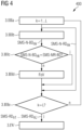
- step 3.III a first of a total of N (N is a natural number) simultaneous image recordings of the examination area FoV is carried out for image display purposes. Simultaneously recorded raw data SMS-RD n are recorded from the examination area FoV. Details of the individual images are in FIG 4 illustrated, wherein sub-steps 3.IIIa to 3.IIIf of step 3.III are shown.
- step 3.IV a simultaneous navigator MR image recording is now carried out, with simultaneous navigator raw data SMS-N-RD n being generated. Simultaneous navigator image data SMS-N-BD n are then reconstructed on the basis of the simultaneous navigator raw data SMS-N-RD n .
- step 3.V the navigator image data SMS-N-BD n reconstructed on the basis of the navigator raw data SMS-N-RD n is then compared with movement reference image data SMS-MR-BD, which are based on the in step 3. II recorded magnetic resonance motion reference raw data SMS-MR-RD were reconstructed.
- movement reference image data SMS-MR-BD which are based on the in step 3. II recorded magnetic resonance motion reference raw data SMS-MR-RD were reconstructed.
- the two compared image datasets do not show different image areas, which is 3 is marked with "j”
- step 3.IV it is determined in step 3.IV that the image area of the navigator image data SMS-N-BD n has shifted in relation to the image area of the motion reference image data SMS-MR-BD, which in 3 marked with "n”, go to step 3.VI.
- step 3.VI the field of view FoV is then corrected in order to compensate for the shift in the recording area.
- step 3.VII the field of view FoV is then corrected in order to compensate for the shift in the recording area.
- step 3.VII the field of view FoV is then corrected in order to compensate for the shift in the recording area.
- FIG 4 a flow chart is shown which corresponds to the in 3 outlined step 3.III illustrated in detail in a special embodiment.
- step 3.III a first raw magnetic resonance data SMS-RD n1 are recorded.
- step 3.IIIb a first navigator image is recorded within an image recording, with navigator raw data SMS-N-RD n1 being recorded using a simultaneous MR imaging method and based on the navigator raw data SMS-N-RD n1 corresponding image data SMS-N-BD n1 are reconstructed.
- step 3.IIIc a comparison is then made between the navigator image data SMS-N-BD n1 and the corresponding part of the step 3.II (see 3 ) reconstructed magnetic resonance motion reference image data SMS-MR-BD performed.
- the two compared image datasets do not show different image areas, which is FIG 4 is marked with "j”
- the transition is made to step 3.IIId.
- step 3.IIId the field of view FoV is now corrected in order to compensate for the shift in the recording area.
- step 3.IVe the field of view FoV is now corrected in order to compensate for the shift in the recording area.
- 5 1 shows a roughly schematic representation of a magnetic resonance system according to the invention or a magnetic resonance imaging system 1. It includes the actual magnetic resonance scanner 2 with a measuring room 8 or patient tunnel located therein. A table 7 can be moved into this patient tunnel 8, so that an examination object O lying on it (e.g. a patient/subject or a material to be examined) is stored during an examination at a specific position within the magnetic resonance scanner 2 relative to the magnet system and radio-frequency system arranged therein can or can also be moved between different positions during a measurement.
- an examination object O lying on it e.g. a patient/subject or a material to be examined
- Essential components of the magnetic resonance scanner 2 are a basic field magnet 3, a gradient system 4 with gradient coils to create any magnetic field gradients in the x, y and z direction, as well as a whole-body high-frequency coil 5.
- local transmission coils can also be used to excite magnetic resonance signals as is the case with knee imaging, for example.
- Magnetic resonance signals induced in the examination object O can be received via the whole-body coil 5, with which the high-frequency signals for inducing the magnetic resonance signals are generally also transmitted. However, these signals are usually received with local coils 6 placed on or under the examination object O, for example. All of these components are known in principle to those skilled in the art and are therefore 5 shown only roughly schematically.
- the whole-body high-frequency coil 5 can, for. B. in the form of a so-called birdcage antenna have a number N of individual antenna rods that can be controlled separately as individual transmission channels S1, ..., SN by a control device 10, d.
- the magnetic resonance tomography system 1 is a pTX-capable system.
- the method according to the invention can also be used on classic magnetic resonance tomography devices with only one transmission channel.
- the magnetic resonance system 1 includes a control device 30 according to an exemplary embodiment of the invention.
- the control device 30 comprises the aforementioned control device 10 and a terminal 20.
- the control device 10 can be a control computer which can also consist of a large number of individual computers which may also be spatially separated and connected to one another via suitable bus systems or cables or the like can exist.
- This control device 10 is connected to the aforementioned terminal 20 via a terminal interface 17, via which an operator can control the entire system 1.
- this terminal 20 has a computer 21 with a keyboard 28, one or more screens 27 and other input devices such as a mouse or the like, so that a graphical user interface is available to the operator.
- the terminal 20 has additional units 22, 22a, 22b, which are used to carry out the method according to the invention.
- the control device 10 has i.a. a gradient control unit 11, which in turn can consist of several subcomponents.
- the individual gradient coils are connected to control signals SGx, SGy, SGz via this gradient control unit 11 .
- These are gradient pulses that are set during a measurement at precisely provided time positions and with an exactly predetermined time profile in order to scan the examination object O and the associated k-space preferably in individual slices SL according to a control sequence AS.
- the control device 10 also has a high-frequency transmission/reception unit 12 . . Magnetic resonance signals can also be received via the transmitter/receiver unit 12 . In this exemplary embodiment, however, this takes place with the aid of the local coils 6.
- the raw data RD received with these local coils 6 are read out by an HF receiving unit 13 and processed.
- the magnetic resonance signals received therefrom or by the whole-body coil 5 by means of the HF transmission/reception unit 12 are transferred as raw data RD to a reconstruction unit 14, which reconstructs the image data BD from them and stores them in a memory 16 and/or via the interface 17 to the Terminal 20 passes for the operator to view.
- the image data BD can also be sent via a network NW stored and/or displayed and evaluated elsewhere. If the local coils 6 have a suitable switching unit, these can also be connected to an HF transmission/reception unit 12 in order to also use the local coils for transmission, particularly in pTX operation.
- the gradient control 11, the HF transmission/reception unit 12 and the reception unit 13 for the local coils 6 are controlled in each case in a coordinated manner by a measurement control unit 15.
- This uses appropriate commands to ensure that a desired gradient pulse train GP is transmitted using suitable gradient control signals SGx, SGy, SGz, and controls the HF transceiver unit 12 in parallel in such a way that a multi-channel pulse train MP is transmitted, i. H. that on the individual transmission channels S1, .
- It must also be ensured that the magnetic resonance signals at the local coils 6 are read out by the HF receiving unit 13 or any signals at the whole-body coil 5 by the HF transmitting/receiving unit 12 at the appropriate time and processed further.
- the measurement control unit 15 specifies the corresponding signals, in particular the multi-channel pulse train MP to the high-frequency transceiver 12 and the gradient pulse train GP to the gradient control unit 11, according to a predefined control protocol P. All control data that must be set during a measurement in accordance with a predetermined control sequence AS are stored in this control protocol P.
- control protocols P for various measurements are usually stored in a memory 16 . These can be selected by the operator via the terminal 20 and, if necessary, varied in order to then have a suitable control protocol P available for the currently desired measurement, with which the measurement control unit 15 can work. Furthermore, the operator can also use a network NW to receive control protocols P, for example from a manufacturer of the magnetic resonance system retrieve and then modify and use them if necessary.
- the magnetic resonance scanner 2 and the associated control device 10 can also have a large number of other components, which are also not explained in detail here.
- the magnetic resonance scanner 2 can also be designed differently, for example with a patient room that is open at the side, and that in principle the high-frequency whole-body coil does not have to be designed as a birdcage antenna.
- the measurement control unit shown is set up to control the scanning unit 2 of the magnetic resonance imaging system 1 with an image acquisition sequence for generating a plurality of image data sets BD of an image acquisition area FoV of an examination object O with differently selected imaging parameters.
- Said image recording sequence AS is generated by a sequence generation unit 22, which in 5 example shown are part of the terminal 20.
- the sequence generation unit 22 receives log data PD from the computer 21.
- Part of the sequence generation unit 22 is a reference sequence generation unit 22a for generating a reference image acquisition partial sequence for acquiring a set of R-RD reference magnetic resonance raw data from an image acquisition area FoV.
- the sequence generation unit 22 also includes an image sequence generation unit 22b for generating a plurality of partial image acquisition sequences for sequentially acquiring raw magnetic resonance data sets SMS-RD n with different imaging parameters, the partial image acquisition sequences each comprising an SMS image acquisition sequence.
- the described units 15 , 22a , 22b , 14 of the control device 30 for controlling the imaging can be included in the magnetic resonance system 1 , as shown, and in particular can also be a component of the control device 10 .
- the units mentioned are available externally as an independent structural unit and are designed for use with a number of different magnetic resonance systems.
Claims (13)
- Procédé d'imagerie par résonnance magnétique de production d'une pluralité d'ensembles (BD) de données d'image d'une région (FoV) de prise d'image d'un objet (O) à examiner, dans lequel- on saisit au moins un ensemble (R-RD) de données brutes de résonnance magnétique de référence de la région (FoV) de prise d'image,- on saisit successivement dans le temps une pluralité d'ensembles (RD) de données brutes de résonnance magnétique, dans lequel on prend au moins une pluralité (SMS-RDn) des ensembles (RD) de données d'image de résonnance magnétique par une séquence de prise d'image SMS,- on effectue une reconstruction d'une pluralité d'ensembles (BD) de données d'image sur la base des ensembles (RD) de données brutes de résonnance magnétique saisies, dans lequel on reconstruit une pluralité d'ensembles (SMS-BDn) de données d'image SMS respectivement sur la base de l'un des ensembles (SMS-RDn) de données brutes de résonnance magnétique pris par une séquence de prise d'image SMS, et respectivement sur la base d'un et du même ensemble (R-RD) de données brutes de résonnance magnétique de référence,caractérisé en ce que
les ensembles (BD) de données d'image comprennent des ensembles (SMS-BDn) de données d'image utilisés pour la représentation imagée de la région de prise d'image et des ensembles (SMS-N-BDn) de données d'image de navigateur, et en ce que on saisit des ensembles (SMS-N-RDn) de données brutes de résonnance magnétique pour la reconstruction d'ensembles (SMS-N-BDn) de données d'image de navigateur entre la prise d'ensembles (SMS-RDn) de données brutes de résonnance magnétique, qui sont utilisés pour la reconstruction d'une représentation imagée de la région (FoV) de prise d'image. - Procédé suivant la revendication 1, dans lequel on saisit, successivement dans le temps, la pluralité d'ensembles (RD) de données brutes de résonnance magnétique avec des paramètres d'imagerie choisis différemment.
- Procédé suivant la revendication 1 ou 2, dans lequel on saisit exactement un ensemble (R-RD) de données brutes de résonnance magnétique de référence de la région (FoV) de prise d'image et on reconstruit tous les ensembles (SMS-BDn) de données d'image SMS, respectivement sur la base de l'un des ensembles (SMS-RDn) de données brutes de résonnance magnétique enregistrées avec une séquence de prise d'image SMS et respectivement sur la base de l'ensemble (R-RD) commun de données brutes de résonnance magnétique de référence.
- Procédé suivant l'une des revendications 1 à 3, dans lequel on saisit un ensemble (SMS-MR-RD) de données brutes de résonnance magnétique pour la reconstruction d'un ensemble (SMS-MR-BD) de données d'image de navigateur de référence, dans lequel on utilise l'ensemble (SMS-MR-BD) de données d'image de navigateur de référence comme image de référence pour une correction de mouvement sur la base des ensembles (SMS-N-BDn) de données d'image de navigateur.
- Procédé suivant l'une des revendications 1 à 4, dans lequel on saisit au moins un ensemble (SMS-N-RDn) de données brutes de résonnance magnétique pour la reconstruction d'ensembles (SMS-N-BDn) de données d'image de navigateur pendant au moins une brève interruption d'un enregistrement d'ensembles (SMS-RDn) de données brutes de résonnance magnétique, qui sont utilisés pour la reconstruction d'une représentation imagée de la région (FoV) de prise d'image.
- Procédé suivant l'une des revendications 1 à 5, dans lequel on saisit, par une séquence de prise d'image SMS, une pluralité des ensembles (SMS-RDn) de données brutes de résonnance magnétique, qui sont utilisés pour la reconstruction d'une représentation imagée de la région (FoV) de prise d'image et on reconstruit les ensembles (SMS-BDn) de données d'image SMS, respectivement sur l'un de la pluralité des ensembles (SMS-RDn) de données brutes de résonnance magnétique, et respectivement sur la base du un ou du même ensemble (R-RD) de données brutes de résonnance magnétique de référence.
- Procédé suivant l'une des revendications 1 à 6, dans lequel on saisit, par une séquence de prise d'image SMS, une pluralité des ensembles (SMS-RDn) de données brutes de résonnance magnétique pour la reconstruction d'ensembles (SMS-N-BDn) de données d'image de navigateur et on reconstruit les ensembles (SMS-N-BDn) de données d'image de navigateur, respectivement sur l'un de la pluralité des ensembles (SMS-N-RDn) de données brutes de résonnance magnétique, et respectivement sur la base du un et du même ensemble (R-RD) de données brutes de résonnance magnétique de référence.
- Procédé suivant la revendication 6 et la revendication 7, dans lequel on reconstruit au moins une partie des ensembles (SMS-N-BDn) de données d'image de navigateur SMS et une partie des ensembles (SMS-BDn) de données d'image SMS sur la base d'un ensemble (R-RD) commun de données brutes de résonnance magnétique de référence.
- Procédé suivant l'une des revendications 2 à 8, dans lequel les paramètres d'imagerie choisis différemment comprennent au moins l'une des grandeurs suivantes :- valeur d'amplitude,- courbe d'amplitude,- instant de début et durée,- nombre des impulsions d'excitation,- type de séquence,- épaisseur de la couche,- orientation de la couche.
- Dispositif (30) de commande, comportant :- une unité (15) de commande conçue pour commander une unité (2) de scan d'un système (1) d'imagerie par résonnance magnétique par une séquence de prise d'image pour la production d'une pluralité d'ensembles (BD) de données d'image d'une région (FoV) de prise d'image d'un objet (O) à examiner,- une unité (22a) de production de séquence de référence conçue pour la production d'une séquence partielle de prise d'image de référence pour la saisie d'au moins un ensemble (R-RD) de données brutes de résonnance magnétique de référence de la région (FoV) de prise d'image,- une unité (22b) de production de séquences d'image conçue pour la production d'une pluralité de séquences partielles de prise d'image pour la saisie successive dans le temps d'ensembles (SMS-RDn, SMS-N-RDn) de données brutes de résonnance magnétique, dans laquelle au moins une pluralité des séquences partielles de prise d'image comprennent une séquence de prise d'image SMS, et- une unité (14) de reconstruction conçue pour la reconstruction d'une pluralité d'ensembles (BD, SMS-BDn, SMS-N-BDn) de données d'image sur la base des ensembles (SMS-RDn, SMS-N-RDn) de données brutes de résonnance magnétique saisis, dans laquelle une pluralité d'ensembles (SMS-BDn) de données d'image SMS sont reconstruits respectivement sur la base de l'un des ensembles (SMS-RDn) de données brutes de résonnance magnétique enregistré par une séquence de prise d'image SMS, et respectivement sur la base d'un et du même ensemble de données (R-RD) brutes de résonnance magnétique de référence,caractérisé en ce que les ensembles (BD) de données d'image comprennent des ensembles (SMS-BDn) de données d'image utilisés pour la représentation imagée de la zone de prise d'image, et des ensembles (SMS-N-BDn) de données d'image de navigateur, et en ce que des ensembles (SMS-N-RDn) de données brutes de résonnance magnétique sont saisis pour la reconstruction d'ensembles (SMS-N-BDn) de données d'image de navigateur entre l'enregistrement d'ensembles (SMS-RDn) de données brutes de résonnance magnétique, qui sont utilisés pour la reconstruction d'une représentation imagée de la région (FoV) de prise d'image.
- Système (1) d'imagerie par résonnance magnétique, comprenant :- une unité (2) de scan et- un dispositif (30) de commande suivant la revendication 10.
- Produit de programme d'ordinateur ayant un programme d'ordinateur, qui peut être chargé directement dans un dispositif de mémoire d'un dispositif (10, 20, 30) de commande d'un système (1) d'imagerie par résonnance magnétique, comprenant des parties de programme pour effectuer tous les stades du procédé suivant l'une des revendications 1 à 9, lorsque le programme d'ordinateur est exécuté dans le dispositif de commande du système d'imagerie par résonnance magnétique.
- Support, déchiffrable par ordinateur, sur lequel sont mémorisées des parties de programme pouvant être lues et réalisées par une unité informatique d'un système d'imagerie par résonnance magnétique pour effectuer tous les stades du procédé suivant l'une des revendications 1 à 9, lorsque les parties de programme sont exécutées par l'unité informatique.
Priority Applications (2)
| Application Number | Priority Date | Filing Date | Title |
|---|---|---|---|
| EP17160758.3A EP3376246B1 (fr) | 2017-03-14 | 2017-03-14 | Production accélérée d'une série d'images par résonance magnétique au moyen de l'imagerie à résonance magnétique multicouches |
| US15/920,964 US10823799B2 (en) | 2017-03-14 | 2018-03-14 | Method and apparatus for accelerated generation of a series of magnetic resonance images with simultaneous multislice imaging |
Applications Claiming Priority (1)
| Application Number | Priority Date | Filing Date | Title |
|---|---|---|---|
| EP17160758.3A EP3376246B1 (fr) | 2017-03-14 | 2017-03-14 | Production accélérée d'une série d'images par résonance magnétique au moyen de l'imagerie à résonance magnétique multicouches |
Publications (2)
| Publication Number | Publication Date |
|---|---|
| EP3376246A1 EP3376246A1 (fr) | 2018-09-19 |
| EP3376246B1 true EP3376246B1 (fr) | 2023-04-26 |
Family
ID=58360838
Family Applications (1)
| Application Number | Title | Priority Date | Filing Date |
|---|---|---|---|
| EP17160758.3A Active EP3376246B1 (fr) | 2017-03-14 | 2017-03-14 | Production accélérée d'une série d'images par résonance magnétique au moyen de l'imagerie à résonance magnétique multicouches |
Country Status (2)
| Country | Link |
|---|---|
| US (1) | US10823799B2 (fr) |
| EP (1) | EP3376246B1 (fr) |
Families Citing this family (4)
| Publication number | Priority date | Publication date | Assignee | Title |
|---|---|---|---|---|
| US10324149B2 (en) * | 2015-10-08 | 2019-06-18 | The General Hospital Corporation | Systems and methods for generalized slice dithered enhanced resolution magnetic resonance imaging |
| EP3441781A1 (fr) * | 2017-08-11 | 2019-02-13 | Siemens Healthcare GmbH | Mesure accélérée de résonance magnétique |
| CN110547799B (zh) * | 2019-08-19 | 2022-10-28 | 上海联影医疗科技股份有限公司 | 磁共振成像方法、计算机设备和计算机可读存储介质 |
| US11740309B2 (en) | 2021-02-02 | 2023-08-29 | Hyperfine Operations, Inc. | Systems and methods for dynamically extending magnetic resonance imaging of a subject |
Family Cites Families (8)
| Publication number | Priority date | Publication date | Assignee | Title |
|---|---|---|---|---|
| US7408345B2 (en) * | 2006-02-06 | 2008-08-05 | The Board Of Trustees Of The Leland Stanford Junior University | Generalized MRI reconstruction with correction for multiple image distortion |
| CN105182263A (zh) * | 2008-04-28 | 2015-12-23 | 康奈尔大学 | 分子mri中的磁敏度精确量化 |
| CN102870000B (zh) * | 2010-02-25 | 2015-11-25 | Mcw研究基金会股份有限公司 | 使用单个和多个通道接收器线圈的用于同时多切片磁共振成象的方法 |
| US9989610B2 (en) * | 2013-10-24 | 2018-06-05 | Siemens Healthcare Gmbh | Multiband slice accelerated imaging with balanced slice-selective gradients |
| DE102015207591A1 (de) * | 2015-04-24 | 2016-10-27 | Siemens Healthcare Gmbh | Verfahren zu einer Bewegungskorrektur von Magnetresonanz-Messdaten |
| US9940713B1 (en) | 2016-11-15 | 2018-04-10 | Siemens Healthcare Gmbh | MR-based navigators for inter-scan and intra-scan motion correction |
| DE102017201477A1 (de) | 2017-01-31 | 2018-08-02 | Siemens Healthcare Gmbh | Neuberechnung einer Gewichtungsmatrix bei Bewegung |
| US10488481B2 (en) * | 2017-02-22 | 2019-11-26 | The General Hospital Corporation | Systems and methods for multislice magetic resonance fingerprinting |
-
2017
- 2017-03-14 EP EP17160758.3A patent/EP3376246B1/fr active Active
-
2018
- 2018-03-14 US US15/920,964 patent/US10823799B2/en active Active
Non-Patent Citations (1)
| Title |
|---|
| KAWIN SETSOMPOP ET AL: "Blipped-controlled aliasing in parallel imaging for simultaneous multislice echo planar imaging with reduced g-factor penalty", MAGNETIC RESONANCE IN MEDICINE, vol. 67, no. 5, 1 May 2012 (2012-05-01), pages 1210 - 1224, XP055027257, ISSN: 0740-3194, DOI: 10.1002/mrm.23097 * |
Also Published As
| Publication number | Publication date |
|---|---|
| US20180267123A1 (en) | 2018-09-20 |
| EP3376246A1 (fr) | 2018-09-19 |
| US10823799B2 (en) | 2020-11-03 |
Similar Documents
| Publication | Publication Date | Title |
|---|---|---|
| DE102014202358B4 (de) | Optimierung von Rephasierungs-Gradientenpulsen bei einer simultanen MR-Anregung mehrerer Schichten | |
| DE102015222835B4 (de) | Magnetresonanzbildgebungsverfahren mit simultaner Bildaufnahme von mehreren Teilvolumen mit einer synchronen Bildaufnahme von Navigatoren | |
| DE102016218955B4 (de) | Optimiertes Magnetresonanz-Schichtmultiplexing-Verfahren | |
| DE102015222833B4 (de) | Verfahren und Vorrichtung zur Ansteuerung eines Magnetresonanzbildgebungssystems zur simultanen Aufnahme von mehreren Teilvolumina | |
| DE102014200006B4 (de) | Rekonstruktion von fehlenden Magnetresonanz-Rohdaten | |
| DE102013219120B3 (de) | Ermittlung von schichtspezifischen Zusatzdaten bei der Aufnahme von Magnetresonanzdaten für mehrere, simultan aufzunehmende Schichten | |
| DE102010038777B4 (de) | Erstellung von MR-Bildern eines vorbestimmten Volumenabschnitts innerhalb eines Untersuchungsobjekts bei kontinuierlicher Tischverschiebung | |
| DE102010032080B4 (de) | Getriggerte Magnetresonanzbildgebung auf der Grundlage einer partiellen parallelen Akquisition (PPA) | |
| EP3376246B1 (fr) | Production accélérée d'une série d'images par résonance magnétique au moyen de l'imagerie à résonance magnétique multicouches | |
| DE102011083406B4 (de) | Verfahren zur Auswahl eines Unterabtastungsschemas für eine MR-Bildgebung, Verfahren zur Magnetresonanz-Bildgebung und Magnetresonanzanlage | |
| DE102009020661A1 (de) | Verfahren zum Betrieb eines bildgebenden Systems sowie bildgebendes System | |
| DE102013205832A1 (de) | Verfahren zur Erzeugung von Bilddaten | |
| EP3413072A1 (fr) | Procédé de multiplexage de couche en irm | |
| DE102014218653A1 (de) | Prospektive Bewegungskorrektur | |
| DE102015207590A1 (de) | Verfahren zu einer Bewegungskompensation während einer Magnetresonanz-Bildgebung | |
| EP3557276A1 (fr) | Procédé et dispositif de commande destinés à la génération d'images par résonance magnétique à l'interieur et à l'exterieur du volume d'homogénéité du champ magnétique b0 | |
| DE102013220326B4 (de) | Paarweise Anordnung von Abtastpunkten bei der MR-Bildgebung | |
| DE102017201477A1 (de) | Neuberechnung einer Gewichtungsmatrix bei Bewegung | |
| EP3460501B1 (fr) | Procédé rm de multiplexage de couche | |
| DE102016200293A1 (de) | Bestimmung von Bewegungszuständen | |
| DE102016200629A1 (de) | Verfahren zur Magnetresonanz-Bildgebung | |
| EP3570060A1 (fr) | Procédé de reconstruction des enregistrements de tomographie par résonance magnétique à résolution temporelle variable | |
| EP3333584B1 (fr) | Optimisation de la détection simultanée de données rm dans des plusieurs éléments de volume ou des tranches | |
| DE102020209382A1 (de) | Verfahren zur Aufnahme von Messdaten mittels einer Magnetresonanzanlage mit einer Korrektur der verwendeten k-Raumtrajektorien | |
| DE102010041659B4 (de) | Erzeugung eines optimierten MR-Bildes eines Untersuchungsobjekts durch Einstrahlen einer mindestens zwei HF-Pulse umfassenden Pulsfolge |
Legal Events
| Date | Code | Title | Description |
|---|---|---|---|
| PUAI | Public reference made under article 153(3) epc to a published international application that has entered the european phase |
Free format text: ORIGINAL CODE: 0009012 |
|
| STAA | Information on the status of an ep patent application or granted ep patent |
Free format text: STATUS: REQUEST FOR EXAMINATION WAS MADE |
|
| 17P | Request for examination filed |
Effective date: 20171220 |
|
| AK | Designated contracting states |
Kind code of ref document: A1 Designated state(s): AL AT BE BG CH CY CZ DE DK EE ES FI FR GB GR HR HU IE IS IT LI LT LU LV MC MK MT NL NO PL PT RO RS SE SI SK SM TR |
|
| AX | Request for extension of the european patent |
Extension state: BA ME |
|
| STAA | Information on the status of an ep patent application or granted ep patent |
Free format text: STATUS: EXAMINATION IS IN PROGRESS |
|
| 17Q | First examination report despatched |
Effective date: 20190426 |
|
| RIC1 | Information provided on ipc code assigned before grant |
Ipc: G01R 33/567 20060101ALI20200430BHEP Ipc: G01R 33/561 20060101AFI20200430BHEP Ipc: G01R 33/483 20060101ALI20200430BHEP |
|
| STAA | Information on the status of an ep patent application or granted ep patent |
Free format text: STATUS: EXAMINATION IS IN PROGRESS |
|
| GRAP | Despatch of communication of intention to grant a patent |
Free format text: ORIGINAL CODE: EPIDOSNIGR1 |
|
| STAA | Information on the status of an ep patent application or granted ep patent |
Free format text: STATUS: GRANT OF PATENT IS INTENDED |
|
| INTG | Intention to grant announced |
Effective date: 20221024 |
|
| GRAS | Grant fee paid |
Free format text: ORIGINAL CODE: EPIDOSNIGR3 |
|
| GRAA | (expected) grant |
Free format text: ORIGINAL CODE: 0009210 |
|
| STAA | Information on the status of an ep patent application or granted ep patent |
Free format text: STATUS: THE PATENT HAS BEEN GRANTED |
|
| AK | Designated contracting states |
Kind code of ref document: B1 Designated state(s): AL AT BE BG CH CY CZ DE DK EE ES FI FR GB GR HR HU IE IS IT LI LT LU LV MC MK MT NL NO PL PT RO RS SE SI SK SM TR |
|
| REG | Reference to a national code |
Ref country code: GB Ref legal event code: FG4D Free format text: NOT ENGLISH |
|
| REG | Reference to a national code |
Ref country code: CH Ref legal event code: EP |
|
| REG | Reference to a national code |
Ref country code: DE Ref legal event code: R096 Ref document number: 502017014647 Country of ref document: DE |
|
| REG | Reference to a national code |
Ref country code: AT Ref legal event code: REF Ref document number: 1563217 Country of ref document: AT Kind code of ref document: T Effective date: 20230515 |
|
| REG | Reference to a national code |
Ref country code: IE Ref legal event code: FG4D Free format text: LANGUAGE OF EP DOCUMENT: GERMAN |
|
| REG | Reference to a national code |
Ref country code: LT Ref legal event code: MG9D |
|
| REG | Reference to a national code |
Ref country code: NL Ref legal event code: MP Effective date: 20230426 |
|
| PG25 | Lapsed in a contracting state [announced via postgrant information from national office to epo] |
Ref country code: NL Free format text: LAPSE BECAUSE OF FAILURE TO SUBMIT A TRANSLATION OF THE DESCRIPTION OR TO PAY THE FEE WITHIN THE PRESCRIBED TIME-LIMIT Effective date: 20230426 |
|
| PG25 | Lapsed in a contracting state [announced via postgrant information from national office to epo] |
Ref country code: SE Free format text: LAPSE BECAUSE OF FAILURE TO SUBMIT A TRANSLATION OF THE DESCRIPTION OR TO PAY THE FEE WITHIN THE PRESCRIBED TIME-LIMIT Effective date: 20230426 Ref country code: PT Free format text: LAPSE BECAUSE OF FAILURE TO SUBMIT A TRANSLATION OF THE DESCRIPTION OR TO PAY THE FEE WITHIN THE PRESCRIBED TIME-LIMIT Effective date: 20230828 Ref country code: NO Free format text: LAPSE BECAUSE OF FAILURE TO SUBMIT A TRANSLATION OF THE DESCRIPTION OR TO PAY THE FEE WITHIN THE PRESCRIBED TIME-LIMIT Effective date: 20230726 Ref country code: ES Free format text: LAPSE BECAUSE OF FAILURE TO SUBMIT A TRANSLATION OF THE DESCRIPTION OR TO PAY THE FEE WITHIN THE PRESCRIBED TIME-LIMIT Effective date: 20230426 |
|
| PG25 | Lapsed in a contracting state [announced via postgrant information from national office to epo] |
Ref country code: RS Free format text: LAPSE BECAUSE OF FAILURE TO SUBMIT A TRANSLATION OF THE DESCRIPTION OR TO PAY THE FEE WITHIN THE PRESCRIBED TIME-LIMIT Effective date: 20230426 Ref country code: PL Free format text: LAPSE BECAUSE OF FAILURE TO SUBMIT A TRANSLATION OF THE DESCRIPTION OR TO PAY THE FEE WITHIN THE PRESCRIBED TIME-LIMIT Effective date: 20230426 Ref country code: LV Free format text: LAPSE BECAUSE OF FAILURE TO SUBMIT A TRANSLATION OF THE DESCRIPTION OR TO PAY THE FEE WITHIN THE PRESCRIBED TIME-LIMIT Effective date: 20230426 Ref country code: LT Free format text: LAPSE BECAUSE OF FAILURE TO SUBMIT A TRANSLATION OF THE DESCRIPTION OR TO PAY THE FEE WITHIN THE PRESCRIBED TIME-LIMIT Effective date: 20230426 Ref country code: IS Free format text: LAPSE BECAUSE OF FAILURE TO SUBMIT A TRANSLATION OF THE DESCRIPTION OR TO PAY THE FEE WITHIN THE PRESCRIBED TIME-LIMIT Effective date: 20230826 Ref country code: HR Free format text: LAPSE BECAUSE OF FAILURE TO SUBMIT A TRANSLATION OF THE DESCRIPTION OR TO PAY THE FEE WITHIN THE PRESCRIBED TIME-LIMIT Effective date: 20230426 Ref country code: GR Free format text: LAPSE BECAUSE OF FAILURE TO SUBMIT A TRANSLATION OF THE DESCRIPTION OR TO PAY THE FEE WITHIN THE PRESCRIBED TIME-LIMIT Effective date: 20230727 |
|
| PG25 | Lapsed in a contracting state [announced via postgrant information from national office to epo] |
Ref country code: FI Free format text: LAPSE BECAUSE OF FAILURE TO SUBMIT A TRANSLATION OF THE DESCRIPTION OR TO PAY THE FEE WITHIN THE PRESCRIBED TIME-LIMIT Effective date: 20230426 |
|
| PG25 | Lapsed in a contracting state [announced via postgrant information from national office to epo] |
Ref country code: SK Free format text: LAPSE BECAUSE OF FAILURE TO SUBMIT A TRANSLATION OF THE DESCRIPTION OR TO PAY THE FEE WITHIN THE PRESCRIBED TIME-LIMIT Effective date: 20230426 |
|
| REG | Reference to a national code |
Ref country code: DE Ref legal event code: R097 Ref document number: 502017014647 Country of ref document: DE |
|
| PG25 | Lapsed in a contracting state [announced via postgrant information from national office to epo] |
Ref country code: SM Free format text: LAPSE BECAUSE OF FAILURE TO SUBMIT A TRANSLATION OF THE DESCRIPTION OR TO PAY THE FEE WITHIN THE PRESCRIBED TIME-LIMIT Effective date: 20230426 Ref country code: SK Free format text: LAPSE BECAUSE OF FAILURE TO SUBMIT A TRANSLATION OF THE DESCRIPTION OR TO PAY THE FEE WITHIN THE PRESCRIBED TIME-LIMIT Effective date: 20230426 Ref country code: RO Free format text: LAPSE BECAUSE OF FAILURE TO SUBMIT A TRANSLATION OF THE DESCRIPTION OR TO PAY THE FEE WITHIN THE PRESCRIBED TIME-LIMIT Effective date: 20230426 Ref country code: EE Free format text: LAPSE BECAUSE OF FAILURE TO SUBMIT A TRANSLATION OF THE DESCRIPTION OR TO PAY THE FEE WITHIN THE PRESCRIBED TIME-LIMIT Effective date: 20230426 Ref country code: DK Free format text: LAPSE BECAUSE OF FAILURE TO SUBMIT A TRANSLATION OF THE DESCRIPTION OR TO PAY THE FEE WITHIN THE PRESCRIBED TIME-LIMIT Effective date: 20230426 Ref country code: CZ Free format text: LAPSE BECAUSE OF FAILURE TO SUBMIT A TRANSLATION OF THE DESCRIPTION OR TO PAY THE FEE WITHIN THE PRESCRIBED TIME-LIMIT Effective date: 20230426 |
|
| RAP2 | Party data changed (patent owner data changed or rights of a patent transferred) |
Owner name: SIEMENS HEALTHINEERS AG |
|
| REG | Reference to a national code |
Ref country code: DE Ref legal event code: R081 Ref document number: 502017014647 Country of ref document: DE Owner name: SIEMENS HEALTHINEERS AG, DE Free format text: FORMER OWNER: SIEMENS HEALTHCARE GMBH, MUENCHEN, DE |
|
| PLBE | No opposition filed within time limit |
Free format text: ORIGINAL CODE: 0009261 |
|
| STAA | Information on the status of an ep patent application or granted ep patent |
Free format text: STATUS: NO OPPOSITION FILED WITHIN TIME LIMIT |
|
| 26N | No opposition filed |
Effective date: 20240129 |