EP3376117A1 - Unité filtrante pour hotte aspirante et hotte aspirante - Google Patents
Unité filtrante pour hotte aspirante et hotte aspirante Download PDFInfo
- Publication number
- EP3376117A1 EP3376117A1 EP18157660.4A EP18157660A EP3376117A1 EP 3376117 A1 EP3376117 A1 EP 3376117A1 EP 18157660 A EP18157660 A EP 18157660A EP 3376117 A1 EP3376117 A1 EP 3376117A1
- Authority
- EP
- European Patent Office
- Prior art keywords
- filter unit
- comb
- housing
- ionization
- unit
- Prior art date
- Legal status (The legal status is an assumption and is not a legal conclusion. Google has not performed a legal analysis and makes no representation as to the accuracy of the status listed.)
- Granted
Links
- 238000000926 separation method Methods 0.000 claims abstract description 32
- 238000001556 precipitation Methods 0.000 claims abstract description 16
- 239000003517 fume Substances 0.000 claims abstract description 15
- 230000001681 protective effect Effects 0.000 claims description 9
- 230000004888 barrier function Effects 0.000 claims description 8
- 238000000605 extraction Methods 0.000 claims description 5
- 238000002955 isolation Methods 0.000 claims description 5
- 125000006850 spacer group Chemical group 0.000 claims description 5
- 239000012811 non-conductive material Substances 0.000 claims description 3
- 230000008021 deposition Effects 0.000 abstract description 7
- 239000004033 plastic Substances 0.000 description 10
- 229920003023 plastic Polymers 0.000 description 10
- 239000007788 liquid Substances 0.000 description 9
- 239000007787 solid Substances 0.000 description 9
- 239000000126 substance Substances 0.000 description 8
- 230000008901 benefit Effects 0.000 description 7
- 238000009413 insulation Methods 0.000 description 6
- 235000019645 odor Nutrition 0.000 description 6
- 239000007921 spray Substances 0.000 description 6
- 238000001914 filtration Methods 0.000 description 5
- 229910052751 metal Inorganic materials 0.000 description 5
- 239000002184 metal Substances 0.000 description 5
- 239000000654 additive Substances 0.000 description 4
- 230000005686 electrostatic field Effects 0.000 description 4
- 229920001707 polybutylene terephthalate Polymers 0.000 description 4
- CBENFWSGALASAD-UHFFFAOYSA-N Ozone Chemical compound [O-][O+]=O CBENFWSGALASAD-UHFFFAOYSA-N 0.000 description 3
- 238000004140 cleaning Methods 0.000 description 3
- 238000010276 construction Methods 0.000 description 3
- 239000000356 contaminant Substances 0.000 description 3
- 239000004519 grease Substances 0.000 description 3
- 238000004519 manufacturing process Methods 0.000 description 3
- 239000000463 material Substances 0.000 description 3
- 239000002245 particle Substances 0.000 description 3
- 230000007704 transition Effects 0.000 description 3
- XLYOFNOQVPJJNP-UHFFFAOYSA-N water Substances O XLYOFNOQVPJJNP-UHFFFAOYSA-N 0.000 description 3
- OKTJSMMVPCPJKN-UHFFFAOYSA-N Carbon Chemical compound [C] OKTJSMMVPCPJKN-UHFFFAOYSA-N 0.000 description 2
- 239000004734 Polyphenylene sulfide Substances 0.000 description 2
- 238000010521 absorption reaction Methods 0.000 description 2
- 230000000996 additive effect Effects 0.000 description 2
- 239000011248 coating agent Substances 0.000 description 2
- 238000000576 coating method Methods 0.000 description 2
- 238000010411 cooking Methods 0.000 description 2
- 238000005516 engineering process Methods 0.000 description 2
- 239000003365 glass fiber Substances 0.000 description 2
- 239000012535 impurity Substances 0.000 description 2
- 238000009434 installation Methods 0.000 description 2
- 230000007246 mechanism Effects 0.000 description 2
- 239000007769 metal material Substances 0.000 description 2
- -1 polybutylene terephthalate Polymers 0.000 description 2
- 229920000069 polyphenylene sulfide Polymers 0.000 description 2
- 239000005871 repellent Substances 0.000 description 2
- 229910021536 Zeolite Inorganic materials 0.000 description 1
- 230000001154 acute effect Effects 0.000 description 1
- 229910052782 aluminium Inorganic materials 0.000 description 1
- XAGFODPZIPBFFR-UHFFFAOYSA-N aluminium Chemical compound [Al] XAGFODPZIPBFFR-UHFFFAOYSA-N 0.000 description 1
- 230000000844 anti-bacterial effect Effects 0.000 description 1
- 239000004020 conductor Substances 0.000 description 1
- 238000011109 contamination Methods 0.000 description 1
- 238000009749 continuous casting Methods 0.000 description 1
- HNPSIPDUKPIQMN-UHFFFAOYSA-N dioxosilane;oxo(oxoalumanyloxy)alumane Chemical compound O=[Si]=O.O=[Al]O[Al]=O HNPSIPDUKPIQMN-UHFFFAOYSA-N 0.000 description 1
- 230000005684 electric field Effects 0.000 description 1
- 239000006260 foam Substances 0.000 description 1
- 239000011810 insulating material Substances 0.000 description 1
- 238000000034 method Methods 0.000 description 1
- 238000006386 neutralization reaction Methods 0.000 description 1
- 239000013618 particulate matter Substances 0.000 description 1
- 230000008569 process Effects 0.000 description 1
- 229910001220 stainless steel Inorganic materials 0.000 description 1
- 239000010935 stainless steel Substances 0.000 description 1
- 239000010457 zeolite Substances 0.000 description 1
Images


Classifications
-
- F—MECHANICAL ENGINEERING; LIGHTING; HEATING; WEAPONS; BLASTING
- F24—HEATING; RANGES; VENTILATING
- F24C—DOMESTIC STOVES OR RANGES ; DETAILS OF DOMESTIC STOVES OR RANGES, OF GENERAL APPLICATION
- F24C15/00—Details
- F24C15/20—Removing cooking fumes
- F24C15/2035—Arrangement or mounting of filters
-
- B—PERFORMING OPERATIONS; TRANSPORTING
- B03—SEPARATION OF SOLID MATERIALS USING LIQUIDS OR USING PNEUMATIC TABLES OR JIGS; MAGNETIC OR ELECTROSTATIC SEPARATION OF SOLID MATERIALS FROM SOLID MATERIALS OR FLUIDS; SEPARATION BY HIGH-VOLTAGE ELECTRIC FIELDS
- B03C—MAGNETIC OR ELECTROSTATIC SEPARATION OF SOLID MATERIALS FROM SOLID MATERIALS OR FLUIDS; SEPARATION BY HIGH-VOLTAGE ELECTRIC FIELDS
- B03C3/00—Separating dispersed particles from gases or vapour, e.g. air, by electrostatic effect
- B03C3/34—Constructional details or accessories or operation thereof
- B03C3/40—Electrode constructions
Definitions
- the invention relates to a filter unit for a fume hood, in particular extractor hood, and a fume hood.
- extractor hoods in particular extractor hoods, which are operated in a kitchen, it is known to filter out liquid and solid impurities and odors from the steam and vapors produced during cooking.
- mechanical filters are usually used in the extractor hood.
- expanded metal filters, perforated metal sheet filters, baffle filters, which can also be referred to as eddy current filters, edge suction filters and porous foam media are used as mechanical filters.
- an extractor hood in which an electrostatic filter unit is used.
- the electrostatic filter unit consists in this extractor hood plate-shaped deposition and counter electrodes and wire-shaped ionization.
- the plate-shaped deposition and counterelectrodes are connected to one another via electrically conductive webs and are arranged so that the air entering the filter element initially flows against the deposition electrodes with wire-shaped ionization elements located therebetween and then reaches the counter electrodes which are offset upwards.
- a disadvantage of this filter unit is that its structure is complex.
- the filter unit can not be removed from the extractor hood due to its construction.
- the object of the present invention is therefore to provide a filter unit for a fume hood and an extractor, which have a simple structure, are easy to handle and yet allow reliable cleaning of fumes and vapors and other contaminated air.
- the invention is based on the finding that this object can be achieved by using a modular electrostatic filter system consisting of individual removable, portable filter units, which can also be referred to as filter modules or as filter cassettes.
- the filter mechanism is based on the electrostatic filter principle and the collecting electrodes and the counter electrodes of the separation stage are each formed in one piece and accommodated in a common housing.
- a filter unit for a fume hood comprising an ionization unit having at least one ionization element and at least one counter electrode and a deposition unit having at least one precipitation electrode and at least one counter electrode.
- the filter unit is characterized in that the ionization unit and the separation unit are accommodated in a common housing which represent precipitation electrodes and the counterelectrodes ribs respectively of a comb profile, the comb profile of the precipitation electrode and the comb profile of the counterelectrodes each represent a one-piece component and the comb profiles interlock with one another in that the ribs of the comb profile of the precipitation electrodes and the ribs of the comb profile of the counterelectrodes are arranged alternately.
- the filter unit is also referred to as a filter module.
- the filter unit is a removable from the extractor, portable filter unit, which is preferably pre-assembled.
- a pre-assembled filter unit is referred to, which can be installed as a unit in the extractor and removed from this in one unit.
- a fume extraction device is referred to, which may be, for example, a cooker hood or a ceiling fan.
- the extractor has a suction gap.
- the suction gap can be formed, for example, between an extractor housing and a deflector plate arranged offset below the extractor housing.
- the Absaugspalt can also be referred to as Randabsaugspalt.
- the filter unit comprises an ionization unit, which may also be referred to as ionization stage, and a separation unit, which may also be referred to as a separation stage.
- the ionization stage has at least one ionization element and at least one counterelectrode.
- the separation stage has at least one collecting electrode and at least one counter electrode.
- the separation stage is connected downstream of the ionization stage in the flow direction of the filter unit.
- the ionization element is subjected to voltage, preferably high voltage. As it flows through contaminated air through the ionization solid and liquid substances are electrostatically charged by the ionization element, which can also be referred to as a spray electrode.
- the precipitation electrodes and the counterelectrodes of the deposition stage represent ribs of a comb profile.
- the ribs of the comb profile have a plate shape.
- the ribs are connected to one another via a comb bottom and thus form the comb profile.
- the comb profile can therefore also be referred to as a rib profile, rib ribs or rib profile.
- the comb profile of the collecting electrode and the comb profile of the counterelectrodes are each a one-piece component.
- the ribs are permanently connected to the comb bottom.
- the rib profiles can be produced for example by continuous casting.
- the comb profiles are arranged in the filter unit so that they engage in one another such that the ribs of the comb profile of the collecting electrodes and the ribs of the comb profile of the counterelectrodes are arranged alternately.
- the comb profiles are arranged so that the ribs of the comb profile of the collecting electrodes and the ribs of the comb profile of the counter electrodes do not touch.
- the air flows through the separation unit in a main flow direction which is parallel to the bottoms of the oppositely disposed comb bottoms and along the ribs of the comb profiles.
- the collecting electrodes that is the comb profile, form the positive electrode, which is subjected to high electrical voltage.
- the counterelectrodes, ie comb profile forms the negative electrode.
- an electrostatic field is formed between the positive and negative electrodes.
- the solid and liquid particles of matter already electrically charged in the ionization unit are deflected out of their flow path by the electrostatic field and deposited on the comb profiles, ie precipitation electrodes and counterelectrodes.
- the comb profiles are designed in one piece, the manufacture and handling of the filter unit are simplified.
- the distances between the mutually parallel plate-shaped ribs of each comb profile are fixed and need not be determined when installing the filter unit in the extractor.
- the stability of the comb profile is increased by the one-piece design of the respective comb profile.
- the comb bottom which connects the ribs of the comb profile with each other, designed as a plate.
- the stability is particularly good. Increasing the stability on the one hand has the advantage that an accidental contact of the collecting electrodes with the counterelectrodes can be prevented and thus a short circuit can be ruled out.
- the handling of the filter unit is improved by the increased stability, so that it can be removed for example from the extractor and, for example, can be cleaned in the dishwasher. Even with this cleaning, a deformation of the profiles is not to be feared by the stability of the comb profiles.
- the filter unit comprises a housing.
- the housing is preferably made of electrically non-conductive material.
- both the ionization unit and the separation unit are accommodated.
- the housing thus represents a common housing for these two units.
- the housing has in particular a box shape.
- the bottom and the top wall of the housing and two side walls are formed by air-impermeable plates.
- the front and back of the housing are open or formed by an air-permeable component, in particular a grid.
- Directional information such as top, bottom, front and back refer, unless otherwise indicated, to a filter unit in a state where it is placed in a vertical suction gap of a fume hood.
- the front side is understood to be the outwardly directed side through which air can enter the filter unit.
- the back faces the interior of the extractor hood.
- the width of the housing and thus the width of the filter unit are preferably greater than their height.
- the comb profiles are arranged in the housing such that the ribs of the comb profiles extend in the height direction of the housing.
- the filter unit has a housing made of electrically non-conductive material, which consists of at least two housing parts.
- the housing parts can also be referred to as housing shells.
- a housing part comprises the top wall and at least part of the two side walls of the housing and the second housing part comprises the bottom and at least the further part of the side walls of the housing.
- a protective grid can still be provided on one or both housing parts, which extends over the front of the housing parts.
- the first housing part may for example be referred to as the lower part of the housing and the second or further housing part may be referred to as the upper part of the housing.
- the comb profile of the collecting electrodes and in the second housing part, the comb profile of the counter electrodes of the separation unit can be maintained.
- the comb profiles are attached to the respective housing part, for example glued or latched or are made in one piece with this.
- the comb profile can be injected into the respective housing part.
- the two housing parts are fastened to each other via at least one attachment point.
- the attachment points are preferably placed on the sides of the housing parts.
- the attachment points can be formed for example by screw domes or locking projections.
- the attachment points can be arranged on the outside of the housing or on the inside of the housing.
- the housing consists of two housing parts and a comb profile is held on each housing part, the assembly of the filter unit is simplified. In particular, only the two housing parts must be connected to each other.
- the counterpart electrode (s) of the ionization unit are also held on the housing parts.
- This may or may be attached to the housing parts or integrated into these.
- the ionization element is preferably fastened via attachment points between the housing parts.
- the attachment points may represent, for example, screw domes or locking projections, which are located at the top of the lower housing part and the underside of the upper housing part.
- corresponding passages for connecting means such as screws are provided.
- the comb profiles are connected to each other in addition to the connection via the housing parts or alternatively to this connection via at least one electrically non-conductive spacer.
- the spacer can also be referred to as insulation element.
- the ionization element in the ionization unit extends perpendicular to the surface directions of the ribs of the comb profiles of the separation unit.
- the ribs are preferably in the height direction of the filter unit and therefore the ionization element preferably extends in the width direction of the filter unit.
- the counter electrode (s) of the ionization unit are in the width direction.
- the ionization element preferably extends over the entire width of the filter unit, so that this lies in front of all the ribs of the comb profiles. Due to the vertical alignment of the ionisationsianas to the ribs, the structure of the filter unit further simplified.
- the ionization element can also be referred to as a spray electrode.
- the ionization element may be an electrically conductive wire.
- the ionization element is a sawtooth profile.
- a sawtooth is an elongated component denotes, projecting from the saw teeth on at least one side.
- the saw teeth can protrude, for example, from the top and bottom of the ionisationsiatas in a plate-like ionization.
- a counterelectrode is provided in the ionization unit above and below the ionization element in each case and the saw teeth are directed to these counterelectrodes.
- the saw teeth are provided only on one side of the sawtooth profile.
- the ionization unit may have only a single counter electrode. This is then arranged with respect to the lonisationsettis so that the saw teeth are directed to the counter electrode.
- attachment points of the housing parts and attachment points of the ionization element are provided on the inside of the housing, these are preferably in a space delimited by a barrier wall from the air flow. Particularly preferably, the attachment points lie in the lateral areas of the housing.
- the barrier wall covers at least a part of the front of the housing and protrudes into the interior of the housing.
- the barrier wall is aligned in the angled region with a rib of a comb profile. In this case, a space is formed by the barrier wall and the rib, which is delimited by the air flow through the filter unit.
- the counter electrode of the separation unit is designed as a part with the counter electrode of the ionization unit.
- the counterelectrode of the ionization unit can be, for example, an extension of the comb bottom of the comb profile of the counterelectrodes of the separation unit. This further simplifies the construction of the filter unit.
- At least one electrical contact element for current and voltage connection is provided on at least one housing wall of the housing. This contact possibility from the outside simplifies the installation of the filter unit in the extractor hood.
- the housing parts on isolation webs at least the leading edge of the ribs of the comb profiles and preferably the Cover the leading edge and the back edge of the ribs of the comb profiles.
- the insulating webs extend from the bottom of the housing or from the top wall of the housing into the interior of the housing and have a height which corresponds to the height of the ribs of the comb profile.
- the filter unit has a protective grid.
- the protective grille serves to increase the stability of the filter unit and, on the other hand, prevents the user's access to the ionization unit or separation unit.
- the invention relates to a fume hood with at least one filter unit.
- the extractor hood is characterized in that in the extractor hood at least two inventively designed filter units are releasably secured.
- filter units according to the invention are provided in the extractor and these represent removable units, the modular design of the filter system of the extractor can be realized in a simple manner.
- the filter units are also releasably attached to the extractor hood. Thus, the filter units can be removed from the extractor, for example, for cleaning purposes.
- the filter units are placed in a vertically extending suction of the extractor hood.
- the filter units can be easily inserted into the suction gap.
- the extractor contact points are provided, which are positioned so that provided on the individual filter units contact elements can be brought into contact with the contact points and the filter units can be supplied with voltage.
- the present invention thus provides a filter technology which is realized by a modular electrostatic filter system.
- the filter system consisting of individual removable, portable filter modules, which can also be referred to as filter cassettes.
- the filter mechanism in each of the filter units is based on the electrostatic filter principle.
- Each individual filter module consists of an ionization unit (ionization stage) and a downstream separation unit (separation stage) in the direction of air flow.
- ionization stage an ionization unit
- a downstream separation unit separation stage
- ozone is generated by the ionization element, which can also be called a spray electrode, which neutralises unpleasant odors from the air.
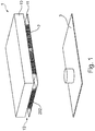
- FIG. 1 is an embodiment of a fume hood according to the invention 1, which can also be referred to as a fume extraction device shown.
- the extractor hood 1 has a vapor-extraction housing 10 and a baffle plate 11 located below, that is to say in the flow direction, in front of the underside of the vapor-extraction housing 10.
- a suction gap 12 Between the bottom of the extractor housing 10 and the baffle plate 11 is a suction gap 12, which may also be referred to as Einsaugspalt formed.
- a plurality of filter units 2 are introduced in the suction gap 12 .
- a filter unit 2 are placed over the width of the extractor 1 and over the depth of the extractor hood 1.
- the extractor hood 1 is mounted above a cooker 3 and can be accommodated, for example, in the ceiling (not shown), wherein at least the suction gap 12 lies at least temporarily below the ceiling.
- the filter units 2 are in the FIG. 1 only the protective grid 202, which form the front sides of the filter units 2, to recognize.
- the filter unit 2 has a lower housing part 201 and an upper housing part 200, which together form the housing 20.
- the two housing parts 200 and 201 each have the same height in the illustrated embodiment.
- the lower housing part 201 consists of a bottom and two side wall pieces.
- the upper housing part 200 consists of a Top wall and two side wall pieces.
- each of the housing parts 200, 201 has a protective grid 202.
- the protective grid 202 is in one piece and either represents a separate component or is connected to the upper or lower housing part 200, 201.
- contact elements 25, 26 are arranged on the upper side of the housing 20, that is, on the top wall of the upper housing part 200.
- FIG. 3 the interior of the filter unit 2 can be seen.
- an ionization unit 22 which is also referred to as ionization stage, and a separation unit 21, which is also referred to as Abscheidemaker formed.
- the ionization unit 22 in this case comprises an ionization element 220, which can also be referred to as a spray electrode.
- two counter electrodes 221, 222 are provided.
- the counter electrodes 221, 222 are arranged and fixed in the front region of the lower housing part 201, in particular on the bottom of the lower housing part 201 or in the front region of the upper housing part 200, in particular on the underside of the top wall of the upper housing part 200.
- the ionization element 220 extends in the width direction of the housing 20 and is disposed at half the height of the housing 20. Thus, the ionization element 220 is located midway between the counter electrodes 221, 222 and parallel to them.
- the ionization element 220 for example, the in FIG. 4
- an electrostatic ionization field is formed in the direction of the two grounded counterelectrodes.
- the sawtooth profile can also be referred to as spike electrodes.
- the saw teeth of the two rows of saw teeth that is, the up and the downwardly directed row of saw teeth are offset from each other to obtain a high ionization.
- the ionization element is installed in the housing 20 of the filter unit 2 for effective charging in the horizontal position or installation situation.
- a thin wire (not shown) may also be used as the ionization element 220.
- wires are used with a diameter of, for example,> 0.1mm.
- the rear portion of the filter unit 2 is in the FIG. 3 formed by the separation unit 21. In this area is the comb profile 210 of the counter electrodes of the separation unit 21 and the comb profile 211 of the collecting electrodes.
- FIG. 5 is the structure of the embodiment of the filter unit 1 according to the invention FIG. 2 shown in exploded view.
- an ionization element 220 in particular a spray electrode is provided in the ionization stage 22 .
- the ionization element 220 is arranged between two negative counterelectrodes 221, 222. As the air flows through the ionization stage 22, solid and liquid substances are charged electrostatically by means of the spray electrode 220.
- the downstream in the flow direction separation stage 21 consists of different, alternately charged electrodes, which are arranged alternately.
- comb profiles 210, 211 are used, which intermesh, but do not touch the ribs.
- the one comb profile 211 or the ribs of this comb profile 211 form the positive, under electrical high voltage precipitation electrode and the comb profile 210 forms the negative counter electrode.
- the upper comb profile 211 is oriented so that its ribs project downwardly and the lower comb profile 210 is oriented so that its ribs project upwardly.
- insulating webs 203 are arranged on the inside of the housing 20 facing side, which extend down into the interior of the housing 20.
- the isolation webs 203 have a height which corresponds to the height of the upper comb profile 211.
- insulating webs 203 are arranged on the inside of the housing 20 facing side, which extend upwardly into the interior of the housing 20.
- the isolation webs 203 have a height that corresponds to the height of the lower comb profile 210.
- an insulation element 212 is arranged in each case in the illustrated embodiment, which extends upwards over the ribs.
- the protective grid 202 is used for safety-related aspects to protect against direct contact of the ionisations institutes 220. Furthermore, various insulation elements 212 can be used in addition, which serve as a spacer between the comb profiles 210, 211 and increase the mechanical rigidity of the entire filter unit 2.
- the electrical contact elements 25, 26 By means of the electrical contact elements 25, 26, the electrical current and voltage supply of the filter unit 2 are carried out. Although the electrical contact elements 25, 26 are shown at the top of the housing 20, they can also be made alternatively on another side of the filter unit.
- FIG. 6 a further embodiment of the filter unit according to the invention is shown.
- This embodiment differs from that in FIG. 2 shown embodiment only by the structure of the ionization unit 22.
- the other structure is the same and will not be described again.
- a single or multi-row Sge leopardionisationselement 2201 arranged in the region of the top wall of the upper housing part 200.
- the saw teeth of the ionization element 220 are directed downwards.
- FIG. 7 On the bottom of the lower housing part 201, the counter electrode 221 of the ionization unit 22 is arranged in the front region.
- the electrical lonisationsfeld builds only in the direction of one negative counter electrode 221.
- the sawtooth rows of the ionization element 220 may be one or more stages.
- the saw teeth of the individual rows of saw teeth should be offset from each other.
- An advantage of the construction after FIG. 6 is that no negative component, such as the counter electrode 222 of the first embodiment of FIG. 2 , in close proximity to the live positive electrode 211. This increases the electrical leakage and short circuit resistance.
- angular and sharp edges are avoided at the junctions on the two comb profiles 210, 211 and the negative counter electrodes 221, 222, because at acute and angular transitions very high electric field strengths form and thus electrical Favor rollovers.
- all transitions (edges, corners) of the comb profiles 210, 211 or grounded counterelectrodes 221, 222 are provided with fillets having a radius of, for example,> 0.2 mm.
- the two-sided end faces of the comb profiles 210, 211 that is the collecting electrode and counter electrode of the separation unit 21 are covered or coated with insulating material, for example with an insulating plastic.
- connection between the positive collecting electrode, that is to say the comb profile 211, and the negative counterelectrode, that is to say the comb profile 210 preferably takes place in the illustrated embodiments via lateral attachment points 23 of the electrically insulating housing 20 and the additional insulating elements 212 the FIGS. 8 and 10 to recognize.
- the attachment points 23 represent in the illustrated embodiment inwardly directed domes, in the example, locking elements (not shown) of the other housing part can engage.
- these lateral attachment points 23, the comb profiles 210, 211 are arranged on the housing 20 as well as the attachment points 24 of the ionization element 220 to the housing 20 in a shielded area.
- a barrier wall 27 is provided on the front side of the housing 20, which shields the lateral area to the front.
- the barrier wall 27 is angled so that it extends into the interior of the housing 20.
- the housing of the filter unit according to the invention which may also be referred to as an electrostatic filter module, preferably consists of a high-voltage resistant plastic.
- a potential plastic for example, glass fiber reinforced polybutylene terephthalate (PBT) or polyphenylene sulfide (PPS) is used.
- PBT polybutylene terephthalate
- PPS polyphenylene sulfide
- the positive collecting electrodes or negative counterelectrodes of the separating unit consist of an electrically conductive material.
- electrically conductive plastics are used. Glass fiber reinforced polybutylene terephthalates (PBT), for example, can likewise be used here.
- PBT polybutylene terephthalates
- the addition of additives into the plastic also improves certain properties with regard to resistance to chemically aggressive substances, high mechanical strength, water-repellent surfaces and low water absorption capacity.
- metallic materials such as aluminum or stainless steel may be used.
- the negative counterelectrodes of the ionization unit are electrically conductive and analogous to the electrodes of the deposition unit of an electrically conductive plastic exist with the properties already mentioned or exist as an alternative from a metallic material.
- all surfaces can optionally be coated with an antibacterial coating or added as an additive to the plastic material.
- the electrodes of the separation unit and the counter electrodes of the ionization unit can be coated with an ozone-neutralizing coating in order to neutralize the ozone in the filter module.
- the ozone-neutralizing material may also be added to the plastic as an additive in the production of said positions.
- the present invention can be applied in fume hoods and similar fume extractors as well as electrostatic air purifiers in the function of a particulate matter filter.
- the advantage of this invention to the known, currently in use grease filter technologies is the significantly higher filtration efficiency in the filtration of solid and liquid substances from the Wrasen Kunststoffstrom.
- liquid and solid particles smaller than 1 ⁇ m are filtered out of the stream of compressed air.
- the downstream extractor components are protected from contamination and other contaminants.
- the downstream odor filters, such as activated carbon filter and zeolite filter for odor filtration are thereby protected against solid and liquid vapor deposits, which increases the life of the odor filter.
- Further advantages of the present invention are, for example, the very high filter performance with low airflow difficulties.
- a very high filtration efficiency can be achieved with the electrostatic filter unit according to the invention, even at low volume flows or air flow rates.
- the inventive electrostatic filter unit also has a low pressure drop.
- the separation unit consists of comb profiles with preferably lateral attachment points. There is thus no contact between the ribs of the respective electrodes.
- the attachment points between the collecting electrodes and the counter electrodes of the separating unit that is to say the positive and negative comb profiles, are preferably located in the flow-calmed space and not directly in the space through which air flows. This avoids that water and grease deposits and other electrically conductive contaminants lead to electrical creepage distances and short circuits between the two comb profiles.
- the filter units can be used in the extractor also outside the cooking process as a room air purifier due to the very high filtration efficiency, for example in the recirculation mode, to increase the air quality of interiors.
- the neutralization of odors by ozone, which is generated in the ionization unit by the ionization element is possible.
- the removability and cleanability of the filter modules is of great advantage.
Landscapes
- Engineering & Computer Science (AREA)
- Chemical & Material Sciences (AREA)
- Combustion & Propulsion (AREA)
- Mechanical Engineering (AREA)
- General Engineering & Computer Science (AREA)
- Electrostatic Separation (AREA)
Applications Claiming Priority (1)
| Application Number | Priority Date | Filing Date | Title |
|---|---|---|---|
| DE102017204061.0A DE102017204061A1 (de) | 2017-03-13 | 2017-03-13 | Filtereinheit für Dunstabzug und Dunstabzug |
Publications (2)
| Publication Number | Publication Date |
|---|---|
| EP3376117A1 true EP3376117A1 (fr) | 2018-09-19 |
| EP3376117B1 EP3376117B1 (fr) | 2023-08-09 |
Family
ID=61256585
Family Applications (1)
| Application Number | Title | Priority Date | Filing Date |
|---|---|---|---|
| EP18157660.4A Active EP3376117B1 (fr) | 2017-03-13 | 2018-02-20 | Unité filtrante pour hotte aspirante et hotte aspirante |
Country Status (3)
| Country | Link |
|---|---|
| EP (1) | EP3376117B1 (fr) |
| DE (1) | DE102017204061A1 (fr) |
| PL (1) | PL3376117T3 (fr) |
Cited By (1)
| Publication number | Priority date | Publication date | Assignee | Title |
|---|---|---|---|---|
| CN110848779A (zh) * | 2019-11-27 | 2020-02-28 | 陈秉江 | 可替换滤网的抽油烟机油网 |
Families Citing this family (4)
| Publication number | Priority date | Publication date | Assignee | Title |
|---|---|---|---|---|
| DE102019216344A1 (de) * | 2019-10-23 | 2021-04-29 | BSH Hausgeräte GmbH | Elektrostatische Filtereinheit für Luftreinigungsvorrichtung und Luftreinigungsvorrichtung |
| DE102019217831A1 (de) * | 2019-11-19 | 2021-05-20 | BSH Hausgeräte GmbH | Filtereinheit für Luftreinigungsvorrichtung und Luftreinigungsvorrichtung |
| DE102020203314A1 (de) | 2020-03-16 | 2021-09-16 | Volkswagen Aktiengesellschaft | Luftreinigungsanordnung für ein Kraftfahrzeug |
| CN113310097A (zh) * | 2021-07-08 | 2021-08-27 | 成都前锋电子有限责任公司 | 一种带自动清洗的油烟净化设备 |
Citations (4)
| Publication number | Priority date | Publication date | Assignee | Title |
|---|---|---|---|---|
| DE2146288A1 (de) | 1971-09-16 | 1973-03-22 | Bosch Hausgeraete Gmbh | Kuechendunstabzugshaube zum abscheiden von wrasen und verunreinigungen aus der raumluft |
| US4643745A (en) * | 1983-12-20 | 1987-02-17 | Nippon Soken, Inc. | Air cleaner using ionic wind |
| TW201111713A (en) * | 2009-09-17 | 2011-04-01 | Chih-Hsing Chen | Household soot exhaust |
| EP2309198A1 (fr) * | 2008-06-24 | 2011-04-13 | Daikin Industries, Ltd. | Dispositif de ventilation |
Family Cites Families (1)
| Publication number | Priority date | Publication date | Assignee | Title |
|---|---|---|---|---|
| JP3059438B1 (ja) * | 1999-05-31 | 2000-07-04 | 株式会社オーデン | 電気集塵ユニット |
-
2017
- 2017-03-13 DE DE102017204061.0A patent/DE102017204061A1/de not_active Withdrawn
-
2018
- 2018-02-20 EP EP18157660.4A patent/EP3376117B1/fr active Active
- 2018-02-20 PL PL18157660.4T patent/PL3376117T3/pl unknown
Patent Citations (4)
| Publication number | Priority date | Publication date | Assignee | Title |
|---|---|---|---|---|
| DE2146288A1 (de) | 1971-09-16 | 1973-03-22 | Bosch Hausgeraete Gmbh | Kuechendunstabzugshaube zum abscheiden von wrasen und verunreinigungen aus der raumluft |
| US4643745A (en) * | 1983-12-20 | 1987-02-17 | Nippon Soken, Inc. | Air cleaner using ionic wind |
| EP2309198A1 (fr) * | 2008-06-24 | 2011-04-13 | Daikin Industries, Ltd. | Dispositif de ventilation |
| TW201111713A (en) * | 2009-09-17 | 2011-04-01 | Chih-Hsing Chen | Household soot exhaust |
Cited By (1)
| Publication number | Priority date | Publication date | Assignee | Title |
|---|---|---|---|---|
| CN110848779A (zh) * | 2019-11-27 | 2020-02-28 | 陈秉江 | 可替换滤网的抽油烟机油网 |
Also Published As
| Publication number | Publication date |
|---|---|
| DE102017204061A1 (de) | 2018-09-13 |
| EP3376117B1 (fr) | 2023-08-09 |
| PL3376117T3 (pl) | 2024-02-26 |
Similar Documents
| Publication | Publication Date | Title |
|---|---|---|
| EP3376117B1 (fr) | Unité filtrante pour hotte aspirante et hotte aspirante | |
| EP3552710B1 (fr) | Unité filtrante électrostatique et dispositif d'extraction pourvu d'unité filtrante électrostatique | |
| WO2018166764A1 (fr) | Unité filtrante pour dispositif d'aspiration et dispositif d'aspiration | |
| DE69309908T2 (de) | Elektrostatischer zwei-stufen filter | |
| EP3775700B1 (fr) | Dispositif d'évacuation de fumée comprenant un dispositif de filtrage | |
| DE202012010239U1 (de) | Vorrichtung zur Luftreinigung | |
| EP3701192A1 (fr) | Appareil combiné comprenant un dispositif d'aspiration des fumées et une table de cuisson | |
| WO2020178153A1 (fr) | Unité de filtration électrostatique pour un dispositif de purification d'air et dispositif de purification d'air | |
| DE2146288A1 (de) | Kuechendunstabzugshaube zum abscheiden von wrasen und verunreinigungen aus der raumluft | |
| WO2021099112A1 (fr) | Unité de filtration pour dispositif de purification d'air et dispositif de purification d'air | |
| DE102017214495A1 (de) | Filtereinheit für Luftreinigungsvorrichtung und Luftreinigungsvorrichtung | |
| DE20018582U1 (de) | Vorrichtung zum Filtern von Luft, insbesondere Luftfiltereinsatz für Filterlüfter insbesondere für Schaltschränke | |
| WO2010091694A1 (fr) | Épurateur d'air électrostatique | |
| EP3517208B1 (fr) | Unité filtrante pour un dispositif d'épuration d'air | |
| EP3517846A1 (fr) | Dispositif d'aération ménager et procédé de fonctionnement d'un dispositif d'aération ménager | |
| DE1557031B2 (de) | Elektroabscheider | |
| EP3552711B1 (fr) | Élément filtrant électrostatique et dispositif d'aération pourvu d'un élément filtrant électrostatique | |
| EP4000738B1 (fr) | Filtre de nettoyage d'un flux gazeux | |
| DE202021105040U1 (de) | Filtervorrichtung und Küchenmodul | |
| DE202021105038U1 (de) | Filtervorrichtung und Küchenmodul | |
| EP4269879A1 (fr) | Unité de filtre pour dispositif d'aspiration de fumées et dispositif d'aspiration de fumées | |
| DE102019217832A1 (de) | Elektrostatische Filtereinheit für Luftreinigungsvorrichtung und Luftreinigungsvorrichtung | |
| DE1557031C (de) | Elektroabscheider | |
| EP4190430A1 (fr) | Unité de filtre pour dispositif d'aspiration de fumées et dispositif d'aspiration de fumées | |
| DE102021214421A1 (de) | Ionisierungseinheit für Dunstabzugsvorrichtung und Dunstabzugsvorrichtung |
Legal Events
| Date | Code | Title | Description |
|---|---|---|---|
| PUAI | Public reference made under article 153(3) epc to a published international application that has entered the european phase |
Free format text: ORIGINAL CODE: 0009012 |
|
| STAA | Information on the status of an ep patent application or granted ep patent |
Free format text: STATUS: THE APPLICATION HAS BEEN PUBLISHED |
|
| AK | Designated contracting states |
Kind code of ref document: A1 Designated state(s): AL AT BE BG CH CY CZ DE DK EE ES FI FR GB GR HR HU IE IS IT LI LT LU LV MC MK MT NL NO PL PT RO RS SE SI SK SM TR |
|
| AX | Request for extension of the european patent |
Extension state: BA ME |
|
| STAA | Information on the status of an ep patent application or granted ep patent |
Free format text: STATUS: REQUEST FOR EXAMINATION WAS MADE |
|
| STAA | Information on the status of an ep patent application or granted ep patent |
Free format text: STATUS: REQUEST FOR EXAMINATION WAS MADE |
|
| 17P | Request for examination filed |
Effective date: 20190319 |
|
| RBV | Designated contracting states (corrected) |
Designated state(s): AL AT BE BG CH CY CZ DE DK EE ES FI FR GB GR HR HU IE IS IT LI LT LU LV MC MK MT NL NO PL PT RO RS SE SI SK SM TR |
|
| STAA | Information on the status of an ep patent application or granted ep patent |
Free format text: STATUS: EXAMINATION IS IN PROGRESS |
|
| 17Q | First examination report despatched |
Effective date: 20210223 |
|
| STAA | Information on the status of an ep patent application or granted ep patent |
Free format text: STATUS: EXAMINATION IS IN PROGRESS |
|
| RIC1 | Information provided on ipc code assigned before grant |
Ipc: B03C 3/40 20060101ALI20230216BHEP Ipc: F24C 15/20 20060101AFI20230216BHEP |
|
| GRAP | Despatch of communication of intention to grant a patent |
Free format text: ORIGINAL CODE: EPIDOSNIGR1 |
|
| STAA | Information on the status of an ep patent application or granted ep patent |
Free format text: STATUS: GRANT OF PATENT IS INTENDED |
|
| INTG | Intention to grant announced |
Effective date: 20230327 |
|
| GRAS | Grant fee paid |
Free format text: ORIGINAL CODE: EPIDOSNIGR3 |
|
| GRAA | (expected) grant |
Free format text: ORIGINAL CODE: 0009210 |
|
| STAA | Information on the status of an ep patent application or granted ep patent |
Free format text: STATUS: THE PATENT HAS BEEN GRANTED |
|
| AK | Designated contracting states |
Kind code of ref document: B1 Designated state(s): AL AT BE BG CH CY CZ DE DK EE ES FI FR GB GR HR HU IE IS IT LI LT LU LV MC MK MT NL NO PL PT RO RS SE SI SK SM TR |
|
| REG | Reference to a national code |
Ref country code: GB Ref legal event code: FG4D Free format text: NOT ENGLISH |
|
| REG | Reference to a national code |
Ref country code: CH Ref legal event code: EP |
|
| REG | Reference to a national code |
Ref country code: IE Ref legal event code: FG4D Free format text: LANGUAGE OF EP DOCUMENT: GERMAN |
|
| REG | Reference to a national code |
Ref country code: DE Ref legal event code: R096 Ref document number: 502018012898 Country of ref document: DE |
|
| REG | Reference to a national code |
Ref country code: LT Ref legal event code: MG9D |
|
| REG | Reference to a national code |
Ref country code: NL Ref legal event code: MP Effective date: 20230809 |
|
| PG25 | Lapsed in a contracting state [announced via postgrant information from national office to epo] |
Ref country code: GR Free format text: LAPSE BECAUSE OF FAILURE TO SUBMIT A TRANSLATION OF THE DESCRIPTION OR TO PAY THE FEE WITHIN THE PRESCRIBED TIME-LIMIT Effective date: 20231110 |
|
| PG25 | Lapsed in a contracting state [announced via postgrant information from national office to epo] |
Ref country code: IS Free format text: LAPSE BECAUSE OF FAILURE TO SUBMIT A TRANSLATION OF THE DESCRIPTION OR TO PAY THE FEE WITHIN THE PRESCRIBED TIME-LIMIT Effective date: 20231209 |
|
| PG25 | Lapsed in a contracting state [announced via postgrant information from national office to epo] |
Ref country code: SE Free format text: LAPSE BECAUSE OF FAILURE TO SUBMIT A TRANSLATION OF THE DESCRIPTION OR TO PAY THE FEE WITHIN THE PRESCRIBED TIME-LIMIT Effective date: 20230809 Ref country code: RS Free format text: LAPSE BECAUSE OF FAILURE TO SUBMIT A TRANSLATION OF THE DESCRIPTION OR TO PAY THE FEE WITHIN THE PRESCRIBED TIME-LIMIT Effective date: 20230809 Ref country code: PT Free format text: LAPSE BECAUSE OF FAILURE TO SUBMIT A TRANSLATION OF THE DESCRIPTION OR TO PAY THE FEE WITHIN THE PRESCRIBED TIME-LIMIT Effective date: 20231211 Ref country code: NO Free format text: LAPSE BECAUSE OF FAILURE TO SUBMIT A TRANSLATION OF THE DESCRIPTION OR TO PAY THE FEE WITHIN THE PRESCRIBED TIME-LIMIT Effective date: 20231109 Ref country code: NL Free format text: LAPSE BECAUSE OF FAILURE TO SUBMIT A TRANSLATION OF THE DESCRIPTION OR TO PAY THE FEE WITHIN THE PRESCRIBED TIME-LIMIT Effective date: 20230809 Ref country code: LV Free format text: LAPSE BECAUSE OF FAILURE TO SUBMIT A TRANSLATION OF THE DESCRIPTION OR TO PAY THE FEE WITHIN THE PRESCRIBED TIME-LIMIT Effective date: 20230809 Ref country code: LT Free format text: LAPSE BECAUSE OF FAILURE TO SUBMIT A TRANSLATION OF THE DESCRIPTION OR TO PAY THE FEE WITHIN THE PRESCRIBED TIME-LIMIT Effective date: 20230809 Ref country code: IS Free format text: LAPSE BECAUSE OF FAILURE TO SUBMIT A TRANSLATION OF THE DESCRIPTION OR TO PAY THE FEE WITHIN THE PRESCRIBED TIME-LIMIT Effective date: 20231209 Ref country code: HR Free format text: LAPSE BECAUSE OF FAILURE TO SUBMIT A TRANSLATION OF THE DESCRIPTION OR TO PAY THE FEE WITHIN THE PRESCRIBED TIME-LIMIT Effective date: 20230809 Ref country code: GR Free format text: LAPSE BECAUSE OF FAILURE TO SUBMIT A TRANSLATION OF THE DESCRIPTION OR TO PAY THE FEE WITHIN THE PRESCRIBED TIME-LIMIT Effective date: 20231110 Ref country code: FI Free format text: LAPSE BECAUSE OF FAILURE TO SUBMIT A TRANSLATION OF THE DESCRIPTION OR TO PAY THE FEE WITHIN THE PRESCRIBED TIME-LIMIT Effective date: 20230809 |
|
| PG25 | Lapsed in a contracting state [announced via postgrant information from national office to epo] |
Ref country code: ES Free format text: LAPSE BECAUSE OF FAILURE TO SUBMIT A TRANSLATION OF THE DESCRIPTION OR TO PAY THE FEE WITHIN THE PRESCRIBED TIME-LIMIT Effective date: 20230809 |
|
| PG25 | Lapsed in a contracting state [announced via postgrant information from national office to epo] |
Ref country code: SM Free format text: LAPSE BECAUSE OF FAILURE TO SUBMIT A TRANSLATION OF THE DESCRIPTION OR TO PAY THE FEE WITHIN THE PRESCRIBED TIME-LIMIT Effective date: 20230809 Ref country code: RO Free format text: LAPSE BECAUSE OF FAILURE TO SUBMIT A TRANSLATION OF THE DESCRIPTION OR TO PAY THE FEE WITHIN THE PRESCRIBED TIME-LIMIT Effective date: 20230809 Ref country code: ES Free format text: LAPSE BECAUSE OF FAILURE TO SUBMIT A TRANSLATION OF THE DESCRIPTION OR TO PAY THE FEE WITHIN THE PRESCRIBED TIME-LIMIT Effective date: 20230809 Ref country code: EE Free format text: LAPSE BECAUSE OF FAILURE TO SUBMIT A TRANSLATION OF THE DESCRIPTION OR TO PAY THE FEE WITHIN THE PRESCRIBED TIME-LIMIT Effective date: 20230809 Ref country code: DK Free format text: LAPSE BECAUSE OF FAILURE TO SUBMIT A TRANSLATION OF THE DESCRIPTION OR TO PAY THE FEE WITHIN THE PRESCRIBED TIME-LIMIT Effective date: 20230809 Ref country code: CZ Free format text: LAPSE BECAUSE OF FAILURE TO SUBMIT A TRANSLATION OF THE DESCRIPTION OR TO PAY THE FEE WITHIN THE PRESCRIBED TIME-LIMIT Effective date: 20230809 Ref country code: SK Free format text: LAPSE BECAUSE OF FAILURE TO SUBMIT A TRANSLATION OF THE DESCRIPTION OR TO PAY THE FEE WITHIN THE PRESCRIBED TIME-LIMIT Effective date: 20230809 |
|
| PGFP | Annual fee paid to national office [announced via postgrant information from national office to epo] |
Ref country code: DE Payment date: 20240229 Year of fee payment: 7 |
|
| REG | Reference to a national code |
Ref country code: DE Ref legal event code: R097 Ref document number: 502018012898 Country of ref document: DE |
|
| PGFP | Annual fee paid to national office [announced via postgrant information from national office to epo] |
Ref country code: TR Payment date: 20240209 Year of fee payment: 7 Ref country code: PL Payment date: 20240214 Year of fee payment: 7 Ref country code: IT Payment date: 20240229 Year of fee payment: 7 Ref country code: BE Payment date: 20240219 Year of fee payment: 7 |
|
| PLBE | No opposition filed within time limit |
Free format text: ORIGINAL CODE: 0009261 |
|
| STAA | Information on the status of an ep patent application or granted ep patent |
Free format text: STATUS: NO OPPOSITION FILED WITHIN TIME LIMIT |
|
| 26N | No opposition filed |
Effective date: 20240513 |
|
| PG25 | Lapsed in a contracting state [announced via postgrant information from national office to epo] |
Ref country code: SI Free format text: LAPSE BECAUSE OF FAILURE TO SUBMIT A TRANSLATION OF THE DESCRIPTION OR TO PAY THE FEE WITHIN THE PRESCRIBED TIME-LIMIT Effective date: 20230809 |