EP3376073A1 - Transmission assembly structure - Google Patents
Transmission assembly structure Download PDFInfo
- Publication number
- EP3376073A1 EP3376073A1 EP16864380.7A EP16864380A EP3376073A1 EP 3376073 A1 EP3376073 A1 EP 3376073A1 EP 16864380 A EP16864380 A EP 16864380A EP 3376073 A1 EP3376073 A1 EP 3376073A1
- Authority
- EP
- European Patent Office
- Prior art keywords
- transmission
- engine
- joining surface
- side joining
- housing
- Prior art date
- Legal status (The legal status is an assumption and is not a legal conclusion. Google has not performed a legal analysis and makes no representation as to the accuracy of the status listed.)
- Granted
Links
Images

Classifications
-
- F—MECHANICAL ENGINEERING; LIGHTING; HEATING; WEAPONS; BLASTING
- F16—ENGINEERING ELEMENTS AND UNITS; GENERAL MEASURES FOR PRODUCING AND MAINTAINING EFFECTIVE FUNCTIONING OF MACHINES OR INSTALLATIONS; THERMAL INSULATION IN GENERAL
- F16H—GEARING
- F16H57/00—General details of gearing
- F16H57/02—Gearboxes; Mounting gearing therein
- F16H57/025—Support of gearboxes, e.g. torque arms, or attachment to other devices
-
- B—PERFORMING OPERATIONS; TRANSPORTING
- B60—VEHICLES IN GENERAL
- B60K—ARRANGEMENT OR MOUNTING OF PROPULSION UNITS OR OF TRANSMISSIONS IN VEHICLES; ARRANGEMENT OR MOUNTING OF PLURAL DIVERSE PRIME-MOVERS IN VEHICLES; AUXILIARY DRIVES FOR VEHICLES; INSTRUMENTATION OR DASHBOARDS FOR VEHICLES; ARRANGEMENTS IN CONNECTION WITH COOLING, AIR INTAKE, GAS EXHAUST OR FUEL SUPPLY OF PROPULSION UNITS IN VEHICLES
- B60K25/00—Auxiliary drives
-
- B—PERFORMING OPERATIONS; TRANSPORTING
- B60—VEHICLES IN GENERAL
- B60K—ARRANGEMENT OR MOUNTING OF PROPULSION UNITS OR OF TRANSMISSIONS IN VEHICLES; ARRANGEMENT OR MOUNTING OF PLURAL DIVERSE PRIME-MOVERS IN VEHICLES; AUXILIARY DRIVES FOR VEHICLES; INSTRUMENTATION OR DASHBOARDS FOR VEHICLES; ARRANGEMENTS IN CONNECTION WITH COOLING, AIR INTAKE, GAS EXHAUST OR FUEL SUPPLY OF PROPULSION UNITS IN VEHICLES
- B60K25/00—Auxiliary drives
- B60K25/02—Auxiliary drives directly from an engine shaft
-
- H—ELECTRICITY
- H02—GENERATION; CONVERSION OR DISTRIBUTION OF ELECTRIC POWER
- H02K—DYNAMO-ELECTRIC MACHINES
- H02K5/00—Casings; Enclosures; Supports
-
- F—MECHANICAL ENGINEERING; LIGHTING; HEATING; WEAPONS; BLASTING
- F02—COMBUSTION ENGINES; HOT-GAS OR COMBUSTION-PRODUCT ENGINE PLANTS
- F02B—INTERNAL-COMBUSTION PISTON ENGINES; COMBUSTION ENGINES IN GENERAL
- F02B67/00—Engines characterised by the arrangement of auxiliary apparatus not being otherwise provided for, e.g. the apparatus having different functions; Driving auxiliary apparatus from engines, not otherwise provided for
-
- F—MECHANICAL ENGINEERING; LIGHTING; HEATING; WEAPONS; BLASTING
- F16—ENGINEERING ELEMENTS AND UNITS; GENERAL MEASURES FOR PRODUCING AND MAINTAINING EFFECTIVE FUNCTIONING OF MACHINES OR INSTALLATIONS; THERMAL INSULATION IN GENERAL
- F16H—GEARING
- F16H57/00—General details of gearing
- F16H57/02—Gearboxes; Mounting gearing therein
- F16H2057/02026—Connection of auxiliaries with a gear case; Mounting of auxiliaries on the gearbox
-
- F—MECHANICAL ENGINEERING; LIGHTING; HEATING; WEAPONS; BLASTING
- F16—ENGINEERING ELEMENTS AND UNITS; GENERAL MEASURES FOR PRODUCING AND MAINTAINING EFFECTIVE FUNCTIONING OF MACHINES OR INSTALLATIONS; THERMAL INSULATION IN GENERAL
- F16H—GEARING
- F16H57/00—General details of gearing
- F16H57/02—Gearboxes; Mounting gearing therein
- F16H2057/02039—Gearboxes for particular applications
- F16H2057/02043—Gearboxes for particular applications for vehicle transmissions
Definitions
- This disclosure relates to a structure for assembling a transmission to an internal combustion engine.
- a transmission is assembled to an internal combustion engine (engine) by joining a transmission-side joining surface formed on a transmission housing of the transmission to an engine-side joining surface formed on a flywheel housing of the internal combustion engine and fastening the transmission housing to the flywheel housing by a plurality of bolts.
- Patent Literature 1 Japanese Unexamined Patent Application Publication No. 2002-316625
- This disclosure provides a transmission assembling structure capable of preventing an engine component from being damaged as much as possible at the time of assembling of a transmission.
- a transmission assembly structure includes: an engine-side joining surface, which is formed on a flywheel housing of an internal combustion engine; a transmission-side joining surface, which is formed on a transmission housing of a transmission and is joined to the engine-side joining surface; an engine component, which is provided on an outside of the engine-side joining surface in a radial direction in the flywheel housing and which protrudes toward a transmission side with respect to the engine-side joining surface; a guide member, which is provided on the engine-side joining surface or in a vicinity of the engine-side joining surface of the flywheel housing and also in a vicinity of the engine component and which protrudes toward the transmission side further than the engine component with respect to the engine-side joining surface; and a guide hole, which is provided on the transmission-side joining surface or in a vicinity of the transmission-side joining surface of the transmission housing and into which the guide member is inserted.
- the guide member may be a guide pin.
- the guide member may be provided on the engine-side joining surface and the guide hole may be provided on the transmission-side joining surface.
- a concave portion radially inwardly recessed may be formed in an outer peripheral portion of the engine-side joining surface and the engine component may be disposed in the concave portion.
- the engine component may be a power steering pump.
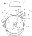
- FIG. 1 is a front view illustrating a transmission assembly structure according to an embodiment.
- FIG. 2 is a cross-sectional view of FIG. 1 taken along line II-II.
- an engine-side joining surface 3 is formed on a flywheel housing 2 of an internal combustion engine (engine) 1 and a transmission-side joining surface 6 which is joined to the engine-side joining surface 3 is formed on a transmission housing 5 of a transmission 4.
- the internal combustion engine in the embodiment is a diesel engine to be mounted in a vehicle such as a truck, but the form, kind, and use of the vehicle and the internal combustion engine and the like are not particularly limited.
- FIG. 1 is a front view when the engine 1 is viewed from the rear side, that is, from the side of the transmission 4.
- a flywheel 7 is rotatably housed and the flywheel 7 is coaxially attached to a rear end portion of a crank shaft 8 by a plurality of bolts (not shown).
- a central axis of the crank shaft 8 is illustrated by C.
- a flywheel gear 9 with which a starter gear 15 is meshed is provided in the outer peripheral portion of the flywheel 7, a flywheel gear 9 with which a starter gear 15 is meshed is provided.
- a bearing 17 formed by a ball bearing is provided in a fixed manner.
- the bearing 17 has a center hole 10.
- the bearing 17 and the center hole 10 are arranged coaxially with the crank shaft 8.
- a clutch mechanism 14 (not illustrated in FIG. 1 ) is assembled on a rear surface portion of the flywheel 7.
- the clutch mechanism 14 is a known dry friction clutch mechanism and includes clutch components such as a clutch disc 14A and a clutch cover 14B. In a center portion of the clutch disc 14A, a spline hole 14C is provided.
- an input shaft 11 of the transmission 4 is rotatably housed.
- a tip end portion 12 of the input shaft 11 protrudes toward a front side with respect to the transmission-side joining surface 6, that is, to the side of the engine 1.
- a tip end shaft portion 16 which is positioned on the forefront side (front side) and is fitted and inserted into the center hole 10
- a spline shaft portion 13 which is positioned adjacent to a rear side of the tip end shaft portion 16 and is fitted and inserted into the spline hole 14C of the clutch disc 14A are formed.
- the spline shaft portion 13 has a larger diameter than the tip end shaft portion 16.
- the clutch mechanism 14 protrudes rearward from the engine-side joining surface 3 and in an assembling state of the transmission 4, the clutch mechanism 14 is housed in the mission housing 5.
- the transmission 4 of the embodiment is a manual transmission.
- the kind of the transmission is arbitrary and the transmission may be, for example, an automatic transmission or a continuously variable transmission.
- a plurality of bolt holes 21 in which female screws are formed are provided on the engine-side joining surface 3.
- a plurality of bolt insertion holes (not shown) for inserting fastening bolts (not shown) are provided at each position corresponding to these bolt holes 21 on the transmission-side joining surface 6, a plurality of bolt insertion holes (not shown) for inserting fastening bolts (not shown) are provided.
- the bolt insertion hole is a through-hole.
- the transmission housing 5 is fastened and fixed to the flywheel housing 2 by inserting the fastening bolts into the bolt insertion holes from the rear side and fastening the bolts to the bolt holes 21.
- a plurality of knock pins 22 are provided to protrude on the engine-side joining surface 3.
- a plurality of knock pin holes (not shown) for fitting the knock pins 22 are provided.
- the knock pin hole is a bottomed hole.
- an auxiliary machine as the engine component specifically, a power steering pump (hereinafter, referred to as "P/S pump") 25 is provided.
- the P/S pump 25 is attached to the flywheel housing 2 by a plurality of bolts 26.
- the P/S pump 25 is connected to the crank shaft 8 through a gear mechanism (not shown) and is driven by the crank shaft 8.
- the P/S pump 25 is provided in a place in the vicinity of the engine-side joining surface 3 in the flywheel housing 2 and protrudes toward the rear side with respect to the engine-side joining surface 3, that is, the side of the transmission 4. More specifically, the P/S pump 25 is provided in a place in the vicinity of the outside of an upper right part 27 of the engine-side joining surface 3 in a radial direction in the front view as illustrated in FIG. 1 .
- a concave portion 28 radially inwardly recessed is formed in an outer peripheral portion of the upper right part 27 of the engine-side joining surface 3, and the P/S pump 25 is disposed in the concave portion 28.
- the P/S pump 25 protrudes toward the rear side with respect to the engine-side joining surface 3 by a protrusion amount (maximum protrusion amount) L1.
- the protrusion amount L1 is larger than a protrusion amount L2 of the knock pin 22.
- a guide pin 30 is provided in a place in the vicinity of the P/S pump 25 on the engine-side joining surface 3.
- a guide hole 31 into which the guide pin 30 is inserted is provided on the transmission-side joining surface 6.
- the guide pin 30 protrudes toward the transmission 4 side further than the P/S pump 25 with respect to the engine-side joining surface 3.
- the guide pin 30 protrudes from the engine-side joining surface 3 by fastening a male screw portion 32 of a base end portion thereof to the screw hole of the engine-side joining surface 3, like a stud bolt.
- a protrusion amount L3 of the guide pin 30 with respect to the engine-side joining surface 3 is larger than the protrusion amount L1 of the P/S pump 25.
- the guide pin 30 is disposed in the region between the bolt holes 21A and 21B where the concave portion 28 is present in the circumferential direction.
- the guide hole 31 is a bottomed hole and is disposed at a position corresponding to the guide pin 30 in the radial direction and the circumferential direction.
- the guide hole 31 has a length L4 which is slightly longer than the protrusion amount L3 of the guide pin 30.
- the transmission 4 is hung and supported by a support device (not shown), is positioned almost coaxially with the engine 1 fixed in advance and is positioned at the almost same position as the engine in the rotational direction.
- the transmission 4 is gradually brought close to the engine 1 and the transmission-side joining surface 6 is gradually brought close to the engine-side joining surface 3.
- the tip end (rear end) of the guide pin 30 positioned at the rearmost side on the engine side abuts on the transmission-side joining surface 6. Since the collision of the transmission-side joining surface 6 with the P/S pump 25 can be avoided, it is possible to prevent the P/S pump 25 from being damaged as much as possible.
- the position of the transmission 4 is finely adjusted and the tip end of the guide pin 30 is inserted into the guide hole 31.
- the transmission 4 is moved to the engine 1 side and the guide pin 30 is deeply inserted into the guide hole 31.
- the transmission 4 is brought close to the engine 1 while being guided by the guide pin 30.
- the movement direction of the transmission 4 is restricted by the guide pin 30, and the transmission 4 is movable to the engine 1 only in axial and circumferential directions of the guide pin 30.
- the transmission-side joining surface 6 is also movable not to the crank shaft 8 but in the circumferential direction of the guide pin 30.
- the rotational movement amount of the transmission 4, which requires fine adjustment, around the guide pin 30 is extremely small and a distance between an inner peripheral surface portion 29 of the concave portion 28 that may collide with the P/S pump 25 and the guide pin 30 is reduced.
- the rotational movement amount of the inner peripheral surface portion 29 of the concave portion 28 at the time of fine adjustment is small. Therefore, it is possible to reliably avoid the inner peripheral surface portion 29 of the concave portion 28 from colliding with the P/S pump 25.
- the position of the transmission 4 around the axis of the crank shaft with respect to the engine 1 is determined. Then, by simply brining the transmission 4 close to the engine 1, the transmission-side joining surface 6 is joined, that is, in surface-contact with the engine-side joining surface 3. Thus, the position of the transmission 4 in the axial direction of the crank shaft with respect to the engine 1 is determined.
- the fastening bolts are inserted into the bolt insertion holes of the transmission 4 side from the rear side and fastened to the bolt holes 21 of the engine 1.
- the transmission housing 5 is fastened and fixed to the flywheel housing 2.
- the guide pin 30 which protrudes toward the transmission 4 side further than the P/S pump 25 is provided in the place in the vicinity of the P/S pump 25, at the time of assembling of the transmission 4, the collision of the transmission housing 5 and the transmission-side joining surface 6 with the P/S pump 25 are reliably avoided, and thus damage of the P/S pump 25 can be prevented as much as possible. At the same time, damage of the transmission housing 5 and the transmission-side joining surface 6 due to collision with the P/S pump 25 can be prevented as much as possible.
- the transmission housing 5 (particularly, the inner peripheral surface portion 29 of the concave portion 28) can be reliably avoided from colliding with the P/S pump 25.
- the transmission-side joining surface 6 can be directly guided to the engine-side joining surface 3 by being guided by the guide pin 30 and workability can be improved.
- the tip end shaft portion 16 is inserted into the center hole 10.
- the operation order may be reversed. That is, in the embodiment, when the position of the rear end of the guide pin 30 coincides with the position of the front end of the guide hole 31, the tip end shaft portion 16 is not yet inserted into the center hole 10. However, the tip end shaft portion may be inserted into the center hole.
- the guide pin 30 is inserted into the guide hole 31 and the position of the transmission 4 around the axis of the crank shaft is finely adjusted.
- the transmission-side joining surface does not abut on the P/S pump 25 only by sliding the transmission-side joining surface 6 on the rear end of the guide pin 30, it is possible to prevent the P/S pump 25 from being damaged as much as possible.
- the transmission assembly structure of this disclosure it is possible to prevent an engine component from being damaged as much as possible at the time of assembling of a transmission.
Landscapes
- Engineering & Computer Science (AREA)
- Mechanical Engineering (AREA)
- General Engineering & Computer Science (AREA)
- Chemical & Material Sciences (AREA)
- Combustion & Propulsion (AREA)
- Transportation (AREA)
- Power Engineering (AREA)
- General Details Of Gearings (AREA)
Abstract
Description
- This disclosure relates to a structure for assembling a transmission to an internal combustion engine.
- Generally, a transmission is assembled to an internal combustion engine (engine) by joining a transmission-side joining surface formed on a transmission housing of the transmission to an engine-side joining surface formed on a flywheel housing of the internal combustion engine and fastening the transmission housing to the flywheel housing by a plurality of bolts.
- [Patent Literature 1]: Japanese Unexamined Patent Application Publication No.
2002-316625 - However, there is a case where an engine component which protrudes toward the transmission side with respect to the engine-side joining surface is provided in a place in the vicinity of the engine-side joining surface in the flywheel housing. In this case, before the transmission-side joining surface abuts on the engine-side joining surface at the time of assembling of the transmission, the transmission-side joining surface abuts on the engine component and thus the engine component may be damaged.
- This disclosure provides a transmission assembling structure capable of preventing an engine component from being damaged as much as possible at the time of assembling of a transmission.
- According to an aspect of this disclosure, a transmission assembly structure includes: an engine-side joining surface, which is formed on a flywheel housing of an internal combustion engine; a transmission-side joining surface, which is formed on a transmission housing of a transmission and is joined to the engine-side joining surface; an engine component, which is provided on an outside of the engine-side joining surface in a radial direction in the flywheel housing and which protrudes toward a transmission side with respect to the engine-side joining surface; a guide member, which is provided on the engine-side joining surface or in a vicinity of the engine-side joining surface of the flywheel housing and also in a vicinity of the engine component and which protrudes toward the transmission side further than the engine component with respect to the engine-side joining surface; and a guide hole, which is provided on the transmission-side joining surface or in a vicinity of the transmission-side joining surface of the transmission housing and into which the guide member is inserted.
- In the transmission assembly structure, the guide member may be a guide pin.
- In the transmission assembly structure, the guide member may be provided on the engine-side joining surface and the guide hole may be provided on the transmission-side joining surface.
- In the transmission assembly structure, a concave portion radially inwardly recessed may be formed in an outer peripheral portion of the engine-side joining surface and the engine component may be disposed in the concave portion.
- In the transmission assembly structure, the engine component may be a power steering pump.
- According to this disclosure, it is possible to prevent an engine component from being damaged at the time of assembling of a transmission as much as possible.
-
-
FIG. 1 is a front view illustrating a transmission assembly structure according to an embodiment. -
FIG. 2 is a cross-sectional view ofFIG. 1 taken along line II-II. - Hereinafter, an embodiment of this disclosure will be described with reference to the accompanying drawings.
-
FIG. 1 is a front view illustrating a transmission assembly structure according to an embodiment.FIG. 2 is a cross-sectional view ofFIG. 1 taken along line II-II. As shown in the drawings, an engine-side joining surface 3 is formed on aflywheel housing 2 of an internal combustion engine (engine) 1 and a transmission-side joining surface 6 which is joined to the engine-side joining surface 3 is formed on atransmission housing 5 of atransmission 4. The internal combustion engine in the embodiment is a diesel engine to be mounted in a vehicle such as a truck, but the form, kind, and use of the vehicle and the internal combustion engine and the like are not particularly limited.FIG. 1 is a front view when theengine 1 is viewed from the rear side, that is, from the side of thetransmission 4. - In the
flywheel housing 2, aflywheel 7 is rotatably housed and theflywheel 7 is coaxially attached to a rear end portion of acrank shaft 8 by a plurality of bolts (not shown). A central axis of thecrank shaft 8 is illustrated by C. In the outer peripheral portion of theflywheel 7, aflywheel gear 9 with which astarter gear 15 is meshed is provided. In a center portion of theflywheel 7, abearing 17 formed by a ball bearing is provided in a fixed manner. Thebearing 17 has acenter hole 10. The bearing 17 and thecenter hole 10 are arranged coaxially with thecrank shaft 8. - A clutch mechanism 14 (not illustrated in
FIG. 1 ) is assembled on a rear surface portion of theflywheel 7. Theclutch mechanism 14 is a known dry friction clutch mechanism and includes clutch components such as aclutch disc 14A and aclutch cover 14B. In a center portion of theclutch disc 14A, aspline hole 14C is provided. - In the
transmission housing 5, aninput shaft 11 of thetransmission 4 is rotatably housed. Atip end portion 12 of theinput shaft 11 protrudes toward a front side with respect to the transmission-side joining surface 6, that is, to the side of theengine 1. At thetip end portion 12, a tipend shaft portion 16 which is positioned on the forefront side (front side) and is fitted and inserted into thecenter hole 10, and aspline shaft portion 13 which is positioned adjacent to a rear side of the tipend shaft portion 16 and is fitted and inserted into thespline hole 14C of theclutch disc 14A are formed. Thespline shaft portion 13 has a larger diameter than the tipend shaft portion 16. - In the embodiment, the
clutch mechanism 14 protrudes rearward from the engine-side joining surface 3 and in an assembling state of thetransmission 4, theclutch mechanism 14 is housed in themission housing 5. Thetransmission 4 of the embodiment is a manual transmission. However, the kind of the transmission is arbitrary and the transmission may be, for example, an automatic transmission or a continuously variable transmission. - As illustrated in
FIG. 1 , on the engine-side joining surface 3, a plurality ofbolt holes 21 in which female screws are formed are provided. At each position corresponding to thesebolt holes 21 on the transmission-side joining surface 6, a plurality of bolt insertion holes (not shown) for inserting fastening bolts (not shown) are provided. The bolt insertion hole is a through-hole. Thetransmission housing 5 is fastened and fixed to theflywheel housing 2 by inserting the fastening bolts into the bolt insertion holes from the rear side and fastening the bolts to thebolt holes 21. - As illustrated in
FIG. 1 , a plurality ofknock pins 22 are provided to protrude on the engine-side joining surface 3. At each position corresponding to theseknock pins 22 on the transmission-side joining surface 6, a plurality of knock pin holes (not shown) for fitting theknock pins 22 are provided. The knock pin hole is a bottomed hole. In a case where the transmission-side joining surface 6 is joined to the engine-side joining surface 3, by fitting theknock pins 22 into the knock pin holes, thetransmission housing 5 is positioned in a rotational direction with respect to theflywheel housing 2 before fixation. - In the
flywheel housing 2, an auxiliary machine as the engine component, specifically, a power steering pump (hereinafter, referred to as "P/S pump") 25 is provided. The P/S pump 25 is attached to theflywheel housing 2 by a plurality ofbolts 26. The P/S pump 25 is connected to thecrank shaft 8 through a gear mechanism (not shown) and is driven by thecrank shaft 8. - The P/
S pump 25 is provided in a place in the vicinity of the engine-side joining surface 3 in theflywheel housing 2 and protrudes toward the rear side with respect to the engine-side joining surface 3, that is, the side of thetransmission 4. More specifically, the P/S pump 25 is provided in a place in the vicinity of the outside of an upperright part 27 of the engine-side joining surface 3 in a radial direction in the front view as illustrated inFIG. 1 . Here, aconcave portion 28 radially inwardly recessed is formed in an outer peripheral portion of the upperright part 27 of the engine-side joining surface 3, and the P/S pump 25 is disposed in theconcave portion 28. At left and right positions on the inside of the P/S pump 25 in the radial direction, twobolt holes S pump 25 are provided. In a region between thesebolt holes concave portion 28 is formed and the P/S pump 25 is disposed. As illustrated inFIG. 2 , the P/S pump 25 protrudes toward the rear side with respect to the engine-side joining surface 3 by a protrusion amount (maximum protrusion amount) L1. The protrusion amount L1 is larger than a protrusion amount L2 of theknock pin 22. - Further, in a place in the vicinity of the P/
S pump 25 on the engine-side joining surface 3, as the guide member, aguide pin 30 is provided. Corresponding to this, aguide hole 31 into which theguide pin 30 is inserted is provided on the transmission-side joining surface 6. Theguide pin 30 protrudes toward thetransmission 4 side further than the P/S pump 25 with respect to the engine-side joining surface 3. - More specifically, the
guide pin 30 protrudes from the engine-side joining surface 3 by fastening amale screw portion 32 of a base end portion thereof to the screw hole of the engine-side joining surface 3, like a stud bolt. A protrusion amount L3 of theguide pin 30 with respect to the engine-side joining surface 3 is larger than the protrusion amount L1 of the P/S pump 25. Theguide pin 30 is disposed in the region between the bolt holes 21A and 21B where theconcave portion 28 is present in the circumferential direction. - The
guide hole 31 is a bottomed hole and is disposed at a position corresponding to theguide pin 30 in the radial direction and the circumferential direction. Theguide hole 31 has a length L4 which is slightly longer than the protrusion amount L3 of theguide pin 30. - Next, a transmission assembling method in the embodiment will be described.
- First, the
transmission 4 is hung and supported by a support device (not shown), is positioned almost coaxially with theengine 1 fixed in advance and is positioned at the almost same position as the engine in the rotational direction. Thetransmission 4 is gradually brought close to theengine 1 and the transmission-side joining surface 6 is gradually brought close to the engine-side joining surface 3. - At this time, in a case where the
guide pin 30 and theguide hole 31 are not in a coaxial relation, first, the tip end (rear end) of theguide pin 30 positioned at the rearmost side on the engine side abuts on the transmission-side joining surface 6. Since the collision of the transmission-side joining surface 6 with the P/S pump 25 can be avoided, it is possible to prevent the P/S pump 25 from being damaged as much as possible. - Then, the position of the
transmission 4 is finely adjusted and the tip end of theguide pin 30 is inserted into theguide hole 31. In this state, thetransmission 4 is moved to theengine 1 side and theguide pin 30 is deeply inserted into theguide hole 31. - Thus, the
transmission 4 is brought close to theengine 1 while being guided by theguide pin 30. The movement direction of thetransmission 4 is restricted by theguide pin 30, and thetransmission 4 is movable to theengine 1 only in axial and circumferential directions of theguide pin 30. In the same manner, the transmission-side joining surface 6 is also movable not to the crankshaft 8 but in the circumferential direction of theguide pin 30. - While the transmission 4 (transmission-side joining surface 6) is brought close to the engine 1 (engine-side joining surface 3) in the axial direction in a state in which the transmission is guided by the
guide pin 30, the rotation position of thetransmission 4 around theguide pin 30 is finely adjusted, and thespline shaft portion 13 and the tipend shaft portion 16 of thetransmission 4 side are respectively inserted into thespline hole 14C and thecenter hole 10 of theengine 1 side to fit the knock pins 22 of theengine 1 side to the knock holes of thetransmission 4 side. - At this time, the rotational movement amount of the
transmission 4, which requires fine adjustment, around theguide pin 30 is extremely small and a distance between an innerperipheral surface portion 29 of theconcave portion 28 that may collide with the P/S pump 25 and theguide pin 30 is reduced. Thus, the rotational movement amount of the innerperipheral surface portion 29 of theconcave portion 28 at the time of fine adjustment is small. Therefore, it is possible to reliably avoid the innerperipheral surface portion 29 of theconcave portion 28 from colliding with the P/S pump 25. - When the tip
end shaft portion 16 is inserted into thecenter hole 10 and the knock pins 22 are fitted to the knock pin holes, the position of thetransmission 4 around the axis of the crank shaft with respect to theengine 1 is determined. Then, by simply brining thetransmission 4 close to theengine 1, the transmission-side joining surface 6 is joined, that is, in surface-contact with the engine-side joining surface 3. Thus, the position of thetransmission 4 in the axial direction of the crank shaft with respect to theengine 1 is determined. - Finally, the fastening bolts are inserted into the bolt insertion holes of the
transmission 4 side from the rear side and fastened to the bolt holes 21 of theengine 1. By repeating this operation, thetransmission housing 5 is fastened and fixed to theflywheel housing 2. - According to the embodiment, since the
guide pin 30 which protrudes toward thetransmission 4 side further than the P/S pump 25 is provided in the place in the vicinity of the P/S pump 25, at the time of assembling of thetransmission 4, the collision of thetransmission housing 5 and the transmission-side joining surface 6 with the P/S pump 25 are reliably avoided, and thus damage of the P/S pump 25 can be prevented as much as possible. At the same time, damage of thetransmission housing 5 and the transmission-side joining surface 6 due to collision with the P/S pump 25 can be prevented as much as possible. Further, in a case where the position of thetransmission 4 around theguide pin 30 is finely adjusted after theguide pin 30 is inserted into theguide hole 31, the transmission housing 5 (particularly, the innerperipheral surface portion 29 of the concave portion 28) can be reliably avoided from colliding with the P/S pump 25. - In the embodiment, since the
guide pin 30 is provided on the engine-side joining surface 3 and theguide hole 31 is provided on the transmission-side joining surface 6, the transmission-side joining surface 6 can be directly guided to the engine-side joining surface 3 by being guided by theguide pin 30 and workability can be improved. - In the embodiment, after the
guide pin 30 is inserted into theguide hole 31, the tipend shaft portion 16 is inserted into thecenter hole 10. However, the operation order may be reversed. That is, in the embodiment, when the position of the rear end of theguide pin 30 coincides with the position of the front end of theguide hole 31, the tipend shaft portion 16 is not yet inserted into thecenter hole 10. However, the tip end shaft portion may be inserted into the center hole. In this case, after the tipend shaft portion 16 is inserted into thecenter hole 10, theguide pin 30 is inserted into theguide hole 31 and the position of thetransmission 4 around the axis of the crank shaft is finely adjusted. However, at this time, since the transmission-side joining surface does not abut on the P/S pump 25 only by sliding the transmission-side joining surface 6 on the rear end of theguide pin 30, it is possible to prevent the P/S pump 25 from being damaged as much as possible. - The embodiment of this disclosure has been described in detail. However, this disclosure can be applied to other embodiments as shown below.
- (1) For example, instead of the above-described
guide pin 30, a guide member may be constituted of a stud bolt that can be used for fastening the transmission housing. In this case, after the guide hole is formed as a through-hole which passes through thetransmission housing 5 and the stud bolt is inserted into the through-hole, a fastening nut is fastened to the stud bolt. In the same manner, the above-describedbolt hole 21 may be replaced with the stud bolt. - (2) As long as the place is a place in the vicinity of the engine component, the guide member may be provided in a place in the vicinity of the engine-side joining surface. Correspondingly, the guide hole may also be provided in a place in the vicinity of the transmission-side joining surface.
- (3) The engine component is not limited to the P/
S pump 25 and may be an arbitrary component. For example, the engine component may be another auxiliary machine driven by the crank shaft. - The embodiment of this disclosure is not limited to the above-described embodiments and all modifications and applications, or equivalents thereof encompassed within the idea of this disclosure defined by the appended claims are also included in this disclosure. Accordingly, this disclosure should not be interpreted in a limited manner, but can also be applied to other arbitrary technologies that belong to the range of the idea of the invention.
- The present application is based on the Japanese patent application (
JP2015-222132) filed on November 12, 2015 - According to the transmission assembly structure of this disclosure, it is possible to prevent an engine component from being damaged as much as possible at the time of assembling of a transmission.
-
- 1: internal combustion engine
- 2: flywheel housing
- 3: engine-side joining surface
- 4: transmission
- 5: transmission housing
- 6: transmission-side joining surface
- 25: power steering pump
- 28: concave portion
- 30: guide pin
- 31: guide hole
Claims (5)
- A transmission assembly structure comprising:an engine-side joining surface, which is formed on a flywheel housing of an internal combustion engine;a transmission-side joining surface, which is formed on a transmission housing of a transmission and is joined to the engine-side joining surface;an engine component, which is provided on an outside of the engine-side joining surface in a radial direction in the flywheel housing and which protrudes toward a transmission side with respect to the engine-side joining surface;a guide member, which is provided on the engine-side joining surface or in a vicinity of the engine-side joining surface of the flywheel housing and also in a vicinity of the engine component and which protrudes toward the transmission side further than the engine component with respect to the engine-side joining surface; anda guide hole, which is provided on the transmission-side joining surface or in a vicinity of the transmission-side joining surface of the transmission housing and into which the guide member is inserted.
- The transmission assembly structure according to claim 1,
wherein the guide member is a guide pin. - The transmission assembly structure according to claim 1 or 2, wherein
the guide member is provided on the engine-side joining surface, and the guide hole is provided on the transmission side joining surface. - The transmission assembly structure according to any one of claims 1 to 3, wherein
a concave portion radially inwardly recessed is formed in an outer peripheral portion of the engine-side joining surface and the engine component is disposed in the concave portion. - The transmission assembly structure according to any one of claims 1 to 4, wherein
the engine component is a power steering pump.
Applications Claiming Priority (2)
| Application Number | Priority Date | Filing Date | Title |
|---|---|---|---|
| JP2015222132A JP6561784B2 (en) | 2015-11-12 | 2015-11-12 | Transmission assembly structure |
| PCT/JP2016/083597 WO2017082419A1 (en) | 2015-11-12 | 2016-11-11 | Transmission assembly structure |
Publications (3)
| Publication Number | Publication Date |
|---|---|
| EP3376073A1 true EP3376073A1 (en) | 2018-09-19 |
| EP3376073A4 EP3376073A4 (en) | 2019-04-03 |
| EP3376073B1 EP3376073B1 (en) | 2021-02-17 |
Family
ID=58695528
Family Applications (1)
| Application Number | Title | Priority Date | Filing Date |
|---|---|---|---|
| EP16864380.7A Active EP3376073B1 (en) | 2015-11-12 | 2016-11-11 | Transmission assembly structure |
Country Status (5)
| Country | Link |
|---|---|
| US (1) | US10760668B2 (en) |
| EP (1) | EP3376073B1 (en) |
| JP (1) | JP6561784B2 (en) |
| CN (1) | CN108291627B (en) |
| WO (1) | WO2017082419A1 (en) |
Families Citing this family (2)
| Publication number | Priority date | Publication date | Assignee | Title |
|---|---|---|---|---|
| JP6537915B2 (en) * | 2015-07-27 | 2019-07-03 | Ntn株式会社 | Pitch cone angle measuring method and measuring apparatus |
| US20250083735A1 (en) * | 2023-09-09 | 2025-03-13 | Schaeffler Technologies AG & Co. KG | Steering gearbox for robotics corner module |
Family Cites Families (18)
| Publication number | Priority date | Publication date | Assignee | Title |
|---|---|---|---|---|
| GB1352516A (en) * | 1970-10-10 | 1974-05-08 | Coventry Climax Eng Ltd | Hydraulic power from a prime mover |
| JPS6036792Y2 (en) * | 1976-08-19 | 1985-10-31 | 川崎重工業株式会社 | engine magneto case |
| JPS61218793A (en) * | 1985-03-25 | 1986-09-29 | Ebara Corp | Centrifugal compressor |
| JPH01193069A (en) * | 1988-01-27 | 1989-08-03 | Daihatsu Motor Co Ltd | Connecting device of transmission case for internal combustion engine |
| US5289738A (en) * | 1992-06-08 | 1994-03-01 | Eaton Corporation | Hydrostatic transaxle assembly and improved coupling arrangement therefor |
| US5404772A (en) * | 1992-11-06 | 1995-04-11 | Dana Corporation | Transmission housing |
| JPH09245887A (en) * | 1996-03-07 | 1997-09-19 | Honda Motor Co Ltd | Connector and automotive parts equipped with this connector |
| DE19911925A1 (en) | 1999-03-17 | 2000-09-21 | Man Nutzfahrzeuge Ag | Arrangement and drive connection of at least one starter / generator to an internal combustion engine |
| JP4975218B2 (en) | 2001-04-19 | 2012-07-11 | いすゞ自動車株式会社 | Power transmission gear parking brake |
| JP2007024130A (en) * | 2005-07-14 | 2007-02-01 | Nissan Motor Co Ltd | Spray bar assembly structure |
| JP5041249B2 (en) * | 2008-12-16 | 2012-10-03 | アイシン・エィ・ダブリュ株式会社 | Vehicle drive device |
| US8826877B2 (en) * | 2009-10-15 | 2014-09-09 | GM Global Technology Operations LLC | Flexible mounting system for powertrain mounted components |
| JP2012241755A (en) * | 2011-05-17 | 2012-12-10 | Honda Motor Co Ltd | Housing of rotating electric machine |
| US20150027402A1 (en) * | 2013-07-26 | 2015-01-29 | Caterpillar Inc. | Thrust plate |
| SE537607C2 (en) * | 2013-11-27 | 2015-07-28 | Scania Cv Ab | Internal combustion engine with flywheel cover |
| JP5990210B2 (en) * | 2014-03-13 | 2016-09-07 | ジヤトコ株式会社 | Case unit and assembly method thereof |
| JP6454212B2 (en) * | 2014-10-15 | 2019-01-16 | ヤンマー株式会社 | Work vehicle |
| CN204657866U (en) * | 2015-03-30 | 2015-09-23 | 西峡县内燃机进排气管有限责任公司 | Turbine case by-passing valve axle sleeve orientation extruding retaining mechanism |
-
2015
- 2015-11-12 JP JP2015222132A patent/JP6561784B2/en active Active
-
2016
- 2016-11-11 EP EP16864380.7A patent/EP3376073B1/en active Active
- 2016-11-11 US US15/775,145 patent/US10760668B2/en active Active
- 2016-11-11 WO PCT/JP2016/083597 patent/WO2017082419A1/en not_active Ceased
- 2016-11-11 CN CN201680065887.XA patent/CN108291627B/en active Active
Also Published As
| Publication number | Publication date |
|---|---|
| JP2017089795A (en) | 2017-05-25 |
| US10760668B2 (en) | 2020-09-01 |
| EP3376073A4 (en) | 2019-04-03 |
| WO2017082419A1 (en) | 2017-05-18 |
| JP6561784B2 (en) | 2019-08-21 |
| EP3376073B1 (en) | 2021-02-17 |
| CN108291627B (en) | 2021-08-31 |
| US20180347683A1 (en) | 2018-12-06 |
| CN108291627A (en) | 2018-07-17 |
Similar Documents
| Publication | Publication Date | Title |
|---|---|---|
| US9982769B2 (en) | Belt pulley arrangment | |
| EP2647832A1 (en) | Internal combustion engine and method for assembling internal combustion engine | |
| EP2514986A2 (en) | Rotational Assembly | |
| EP2614978A2 (en) | Driving device for hybrid working machine | |
| US20120128521A1 (en) | Oil pump arrangement in a transmission | |
| US10760668B2 (en) | Transmission assembly structure | |
| US8550956B2 (en) | Planetary gear unit | |
| US20160109016A1 (en) | Joining structure of power source and transmission | |
| EP3209873B1 (en) | Accessory assembly of a turbine engine | |
| DE102019218983A1 (en) | DRIVING DEVICE FOR A HYBRID VEHICLE | |
| US11215271B2 (en) | Toothing arrangement | |
| US11628717B2 (en) | Hybrid drive train | |
| EP2799707B1 (en) | Method for mounting an electrical machine | |
| EP3214340A1 (en) | Worm reducer and electrically driven assist device | |
| US8597129B2 (en) | Device for a drive connection | |
| DE102018200569B3 (en) | Hybrid drive module for a motor vehicle | |
| US20200231201A1 (en) | Steering Systems for a Vehicle | |
| KR20100008471A (en) | Hybrid transmission of vehicle and assembly method thereof | |
| WO2014054491A1 (en) | Pinion shaft fixing structure for planetary gear | |
| US11306623B2 (en) | System consisting of a camshaft and a camshaft sleeve | |
| EP3230626A1 (en) | Scissor gear assembly with integral isolation mechanism | |
| US20250243932A1 (en) | Parking lock arrangement for a vehicle transmission | |
| JP2015209766A (en) | Starter | |
| EP3707400B1 (en) | Transmission input shaft arrangement | |
| CN210397642U (en) | Speed changing mechanism of electrical appliance device |
Legal Events
| Date | Code | Title | Description |
|---|---|---|---|
| STAA | Information on the status of an ep patent application or granted ep patent |
Free format text: STATUS: THE INTERNATIONAL PUBLICATION HAS BEEN MADE |
|
| PUAI | Public reference made under article 153(3) epc to a published international application that has entered the european phase |
Free format text: ORIGINAL CODE: 0009012 |
|
| STAA | Information on the status of an ep patent application or granted ep patent |
Free format text: STATUS: REQUEST FOR EXAMINATION WAS MADE |
|
| 17P | Request for examination filed |
Effective date: 20180612 |
|
| AK | Designated contracting states |
Kind code of ref document: A1 Designated state(s): AL AT BE BG CH CY CZ DE DK EE ES FI FR GB GR HR HU IE IS IT LI LT LU LV MC MK MT NL NO PL PT RO RS SE SI SK SM TR |
|
| AX | Request for extension of the european patent |
Extension state: BA ME |
|
| DAV | Request for validation of the european patent (deleted) | ||
| DAX | Request for extension of the european patent (deleted) | ||
| A4 | Supplementary search report drawn up and despatched |
Effective date: 20190306 |
|
| RIC1 | Information provided on ipc code assigned before grant |
Ipc: H02K 5/00 20060101ALI20190227BHEP Ipc: F02B 77/00 20060101ALI20190227BHEP Ipc: F16H 57/025 20120101AFI20190227BHEP Ipc: F02B 67/00 20060101ALN20190227BHEP Ipc: F16H 57/02 20120101ALN20190227BHEP Ipc: B60K 25/00 20060101ALI20190227BHEP |
|
| STAA | Information on the status of an ep patent application or granted ep patent |
Free format text: STATUS: EXAMINATION IS IN PROGRESS |
|
| 17Q | First examination report despatched |
Effective date: 20191128 |
|
| RIC1 | Information provided on ipc code assigned before grant |
Ipc: F16H 57/02 20120101ALN20200727BHEP Ipc: B60K 25/00 20060101ALI20200727BHEP Ipc: F16H 57/025 20120101AFI20200727BHEP Ipc: F02B 67/00 20060101ALN20200727BHEP Ipc: F02B 77/00 20060101ALI20200727BHEP Ipc: H02K 5/00 20060101ALI20200727BHEP |
|
| GRAP | Despatch of communication of intention to grant a patent |
Free format text: ORIGINAL CODE: EPIDOSNIGR1 |
|
| STAA | Information on the status of an ep patent application or granted ep patent |
Free format text: STATUS: GRANT OF PATENT IS INTENDED |
|
| INTG | Intention to grant announced |
Effective date: 20200921 |
|
| GRAS | Grant fee paid |
Free format text: ORIGINAL CODE: EPIDOSNIGR3 |
|
| GRAA | (expected) grant |
Free format text: ORIGINAL CODE: 0009210 |
|
| STAA | Information on the status of an ep patent application or granted ep patent |
Free format text: STATUS: THE PATENT HAS BEEN GRANTED |
|
| AK | Designated contracting states |
Kind code of ref document: B1 Designated state(s): AL AT BE BG CH CY CZ DE DK EE ES FI FR GB GR HR HU IE IS IT LI LT LU LV MC MK MT NL NO PL PT RO RS SE SI SK SM TR |
|
| REG | Reference to a national code |
Ref country code: GB Ref legal event code: FG4D |
|
| REG | Reference to a national code |
Ref country code: CH Ref legal event code: EP |
|
| REG | Reference to a national code |
Ref country code: DE Ref legal event code: R096 Ref document number: 602016052826 Country of ref document: DE |
|
| REG | Reference to a national code |
Ref country code: AT Ref legal event code: REF Ref document number: 1361892 Country of ref document: AT Kind code of ref document: T Effective date: 20210315 |
|
| REG | Reference to a national code |
Ref country code: IE Ref legal event code: FG4D |
|
| REG | Reference to a national code |
Ref country code: LT Ref legal event code: MG9D |
|
| REG | Reference to a national code |
Ref country code: NL Ref legal event code: MP Effective date: 20210217 |
|
| PG25 | Lapsed in a contracting state [announced via postgrant information from national office to epo] |
Ref country code: HR Free format text: LAPSE BECAUSE OF FAILURE TO SUBMIT A TRANSLATION OF THE DESCRIPTION OR TO PAY THE FEE WITHIN THE PRESCRIBED TIME-LIMIT Effective date: 20210217 Ref country code: FI Free format text: LAPSE BECAUSE OF FAILURE TO SUBMIT A TRANSLATION OF THE DESCRIPTION OR TO PAY THE FEE WITHIN THE PRESCRIBED TIME-LIMIT Effective date: 20210217 Ref country code: GR Free format text: LAPSE BECAUSE OF FAILURE TO SUBMIT A TRANSLATION OF THE DESCRIPTION OR TO PAY THE FEE WITHIN THE PRESCRIBED TIME-LIMIT Effective date: 20210518 Ref country code: NO Free format text: LAPSE BECAUSE OF FAILURE TO SUBMIT A TRANSLATION OF THE DESCRIPTION OR TO PAY THE FEE WITHIN THE PRESCRIBED TIME-LIMIT Effective date: 20210517 Ref country code: PT Free format text: LAPSE BECAUSE OF FAILURE TO SUBMIT A TRANSLATION OF THE DESCRIPTION OR TO PAY THE FEE WITHIN THE PRESCRIBED TIME-LIMIT Effective date: 20210617 Ref country code: BG Free format text: LAPSE BECAUSE OF FAILURE TO SUBMIT A TRANSLATION OF THE DESCRIPTION OR TO PAY THE FEE WITHIN THE PRESCRIBED TIME-LIMIT Effective date: 20210517 Ref country code: LT Free format text: LAPSE BECAUSE OF FAILURE TO SUBMIT A TRANSLATION OF THE DESCRIPTION OR TO PAY THE FEE WITHIN THE PRESCRIBED TIME-LIMIT Effective date: 20210217 |
|
| REG | Reference to a national code |
Ref country code: AT Ref legal event code: MK05 Ref document number: 1361892 Country of ref document: AT Kind code of ref document: T Effective date: 20210217 |
|
| PG25 | Lapsed in a contracting state [announced via postgrant information from national office to epo] |
Ref country code: SE Free format text: LAPSE BECAUSE OF FAILURE TO SUBMIT A TRANSLATION OF THE DESCRIPTION OR TO PAY THE FEE WITHIN THE PRESCRIBED TIME-LIMIT Effective date: 20210217 Ref country code: RS Free format text: LAPSE BECAUSE OF FAILURE TO SUBMIT A TRANSLATION OF THE DESCRIPTION OR TO PAY THE FEE WITHIN THE PRESCRIBED TIME-LIMIT Effective date: 20210217 Ref country code: NL Free format text: LAPSE BECAUSE OF FAILURE TO SUBMIT A TRANSLATION OF THE DESCRIPTION OR TO PAY THE FEE WITHIN THE PRESCRIBED TIME-LIMIT Effective date: 20210217 Ref country code: LV Free format text: LAPSE BECAUSE OF FAILURE TO SUBMIT A TRANSLATION OF THE DESCRIPTION OR TO PAY THE FEE WITHIN THE PRESCRIBED TIME-LIMIT Effective date: 20210217 Ref country code: PL Free format text: LAPSE BECAUSE OF FAILURE TO SUBMIT A TRANSLATION OF THE DESCRIPTION OR TO PAY THE FEE WITHIN THE PRESCRIBED TIME-LIMIT Effective date: 20210217 |
|
| PG25 | Lapsed in a contracting state [announced via postgrant information from national office to epo] |
Ref country code: IS Free format text: LAPSE BECAUSE OF FAILURE TO SUBMIT A TRANSLATION OF THE DESCRIPTION OR TO PAY THE FEE WITHIN THE PRESCRIBED TIME-LIMIT Effective date: 20210617 |
|
| PG25 | Lapsed in a contracting state [announced via postgrant information from national office to epo] |
Ref country code: EE Free format text: LAPSE BECAUSE OF FAILURE TO SUBMIT A TRANSLATION OF THE DESCRIPTION OR TO PAY THE FEE WITHIN THE PRESCRIBED TIME-LIMIT Effective date: 20210217 Ref country code: CZ Free format text: LAPSE BECAUSE OF FAILURE TO SUBMIT A TRANSLATION OF THE DESCRIPTION OR TO PAY THE FEE WITHIN THE PRESCRIBED TIME-LIMIT Effective date: 20210217 Ref country code: SM Free format text: LAPSE BECAUSE OF FAILURE TO SUBMIT A TRANSLATION OF THE DESCRIPTION OR TO PAY THE FEE WITHIN THE PRESCRIBED TIME-LIMIT Effective date: 20210217 Ref country code: AT Free format text: LAPSE BECAUSE OF FAILURE TO SUBMIT A TRANSLATION OF THE DESCRIPTION OR TO PAY THE FEE WITHIN THE PRESCRIBED TIME-LIMIT Effective date: 20210217 |
|
| REG | Reference to a national code |
Ref country code: DE Ref legal event code: R097 Ref document number: 602016052826 Country of ref document: DE |
|
| PG25 | Lapsed in a contracting state [announced via postgrant information from national office to epo] |
Ref country code: DK Free format text: LAPSE BECAUSE OF FAILURE TO SUBMIT A TRANSLATION OF THE DESCRIPTION OR TO PAY THE FEE WITHIN THE PRESCRIBED TIME-LIMIT Effective date: 20210217 Ref country code: RO Free format text: LAPSE BECAUSE OF FAILURE TO SUBMIT A TRANSLATION OF THE DESCRIPTION OR TO PAY THE FEE WITHIN THE PRESCRIBED TIME-LIMIT Effective date: 20210217 Ref country code: SK Free format text: LAPSE BECAUSE OF FAILURE TO SUBMIT A TRANSLATION OF THE DESCRIPTION OR TO PAY THE FEE WITHIN THE PRESCRIBED TIME-LIMIT Effective date: 20210217 |
|
| PLBE | No opposition filed within time limit |
Free format text: ORIGINAL CODE: 0009261 |
|
| STAA | Information on the status of an ep patent application or granted ep patent |
Free format text: STATUS: NO OPPOSITION FILED WITHIN TIME LIMIT |
|
| 26N | No opposition filed |
Effective date: 20211118 |
|
| PG25 | Lapsed in a contracting state [announced via postgrant information from national office to epo] |
Ref country code: AL Free format text: LAPSE BECAUSE OF FAILURE TO SUBMIT A TRANSLATION OF THE DESCRIPTION OR TO PAY THE FEE WITHIN THE PRESCRIBED TIME-LIMIT Effective date: 20210217 Ref country code: ES Free format text: LAPSE BECAUSE OF FAILURE TO SUBMIT A TRANSLATION OF THE DESCRIPTION OR TO PAY THE FEE WITHIN THE PRESCRIBED TIME-LIMIT Effective date: 20210217 |
|
| PGFP | Annual fee paid to national office [announced via postgrant information from national office to epo] |
Ref country code: FR Payment date: 20211130 Year of fee payment: 6 Ref country code: GB Payment date: 20211015 Year of fee payment: 6 |
|
| PG25 | Lapsed in a contracting state [announced via postgrant information from national office to epo] |
Ref country code: SI Free format text: LAPSE BECAUSE OF FAILURE TO SUBMIT A TRANSLATION OF THE DESCRIPTION OR TO PAY THE FEE WITHIN THE PRESCRIBED TIME-LIMIT Effective date: 20210217 |
|
| PG25 | Lapsed in a contracting state [announced via postgrant information from national office to epo] |
Ref country code: IT Free format text: LAPSE BECAUSE OF FAILURE TO SUBMIT A TRANSLATION OF THE DESCRIPTION OR TO PAY THE FEE WITHIN THE PRESCRIBED TIME-LIMIT Effective date: 20210217 |
|
| PG25 | Lapsed in a contracting state [announced via postgrant information from national office to epo] |
Ref country code: IS Free format text: LAPSE BECAUSE OF FAILURE TO SUBMIT A TRANSLATION OF THE DESCRIPTION OR TO PAY THE FEE WITHIN THE PRESCRIBED TIME-LIMIT Effective date: 20210617 |
|
| PG25 | Lapsed in a contracting state [announced via postgrant information from national office to epo] |
Ref country code: MC Free format text: LAPSE BECAUSE OF FAILURE TO SUBMIT A TRANSLATION OF THE DESCRIPTION OR TO PAY THE FEE WITHIN THE PRESCRIBED TIME-LIMIT Effective date: 20210217 |
|
| REG | Reference to a national code |
Ref country code: CH Ref legal event code: PL |
|
| PG25 | Lapsed in a contracting state [announced via postgrant information from national office to epo] |
Ref country code: LU Free format text: LAPSE BECAUSE OF NON-PAYMENT OF DUE FEES Effective date: 20211111 Ref country code: BE Free format text: LAPSE BECAUSE OF NON-PAYMENT OF DUE FEES Effective date: 20211130 |
|
| REG | Reference to a national code |
Ref country code: BE Ref legal event code: MM Effective date: 20211130 |
|
| PG25 | Lapsed in a contracting state [announced via postgrant information from national office to epo] |
Ref country code: LI Free format text: LAPSE BECAUSE OF NON-PAYMENT OF DUE FEES Effective date: 20211130 Ref country code: CH Free format text: LAPSE BECAUSE OF NON-PAYMENT OF DUE FEES Effective date: 20211130 |
|
| PG25 | Lapsed in a contracting state [announced via postgrant information from national office to epo] |
Ref country code: IE Free format text: LAPSE BECAUSE OF NON-PAYMENT OF DUE FEES Effective date: 20211111 |
|
| PG25 | Lapsed in a contracting state [announced via postgrant information from national office to epo] |
Ref country code: HU Free format text: LAPSE BECAUSE OF FAILURE TO SUBMIT A TRANSLATION OF THE DESCRIPTION OR TO PAY THE FEE WITHIN THE PRESCRIBED TIME-LIMIT; INVALID AB INITIO Effective date: 20161111 |
|
| PG25 | Lapsed in a contracting state [announced via postgrant information from national office to epo] |
Ref country code: CY Free format text: LAPSE BECAUSE OF FAILURE TO SUBMIT A TRANSLATION OF THE DESCRIPTION OR TO PAY THE FEE WITHIN THE PRESCRIBED TIME-LIMIT Effective date: 20210217 |
|
| GBPC | Gb: european patent ceased through non-payment of renewal fee |
Effective date: 20221111 |
|
| PG25 | Lapsed in a contracting state [announced via postgrant information from national office to epo] |
Ref country code: GB Free format text: LAPSE BECAUSE OF NON-PAYMENT OF DUE FEES Effective date: 20221111 |
|
| PG25 | Lapsed in a contracting state [announced via postgrant information from national office to epo] |
Ref country code: FR Free format text: LAPSE BECAUSE OF NON-PAYMENT OF DUE FEES Effective date: 20221130 |
|
| PG25 | Lapsed in a contracting state [announced via postgrant information from national office to epo] |
Ref country code: MK Free format text: LAPSE BECAUSE OF FAILURE TO SUBMIT A TRANSLATION OF THE DESCRIPTION OR TO PAY THE FEE WITHIN THE PRESCRIBED TIME-LIMIT Effective date: 20210217 |
|
| REG | Reference to a national code |
Ref country code: DE Ref legal event code: R082 Ref document number: 602016052826 Country of ref document: DE Representative=s name: MEISSNER BOLTE PATENTANWAELTE RECHTSANWAELTE P, DE |
|
| PG25 | Lapsed in a contracting state [announced via postgrant information from national office to epo] |
Ref country code: MT Free format text: LAPSE BECAUSE OF FAILURE TO SUBMIT A TRANSLATION OF THE DESCRIPTION OR TO PAY THE FEE WITHIN THE PRESCRIBED TIME-LIMIT Effective date: 20210217 |
|
| PG25 | Lapsed in a contracting state [announced via postgrant information from national office to epo] |
Ref country code: TR Free format text: LAPSE BECAUSE OF FAILURE TO SUBMIT A TRANSLATION OF THE DESCRIPTION OR TO PAY THE FEE WITHIN THE PRESCRIBED TIME-LIMIT Effective date: 20210217 |
|
| PGFP | Annual fee paid to national office [announced via postgrant information from national office to epo] |
Ref country code: DE Payment date: 20251022 Year of fee payment: 10 |