EP3375993A1 - Oil level detecting device - Google Patents
Oil level detecting device Download PDFInfo
- Publication number
- EP3375993A1 EP3375993A1 EP16864351.8A EP16864351A EP3375993A1 EP 3375993 A1 EP3375993 A1 EP 3375993A1 EP 16864351 A EP16864351 A EP 16864351A EP 3375993 A1 EP3375993 A1 EP 3375993A1
- Authority
- EP
- European Patent Office
- Prior art keywords
- oil level
- oil
- guide tube
- insertion hole
- detecting device
- Prior art date
- Legal status (The legal status is an assumption and is not a legal conclusion. Google has not performed a legal analysis and makes no representation as to the accuracy of the status listed.)
- Withdrawn
Links
- 238000003780 insertion Methods 0.000 claims abstract description 34
- 230000037431 insertion Effects 0.000 claims abstract description 34
- 238000005192 partition Methods 0.000 claims abstract description 12
- 239000003921 oil Substances 0.000 description 79
- 239000007769 metal material Substances 0.000 description 5
- 229920006015 heat resistant resin Polymers 0.000 description 3
- 239000010705 motor oil Substances 0.000 description 3
- 230000000694 effects Effects 0.000 description 2
- 238000004519 manufacturing process Methods 0.000 description 2
- 239000000463 material Substances 0.000 description 2
- 238000000034 method Methods 0.000 description 2
- 230000000994 depressogenic effect Effects 0.000 description 1
- 238000003825 pressing Methods 0.000 description 1
Images


Classifications
-
- G—PHYSICS
- G01—MEASURING; TESTING
- G01F—MEASURING VOLUME, VOLUME FLOW, MASS FLOW OR LIQUID LEVEL; METERING BY VOLUME
- G01F23/00—Indicating or measuring liquid level or level of fluent solid material, e.g. indicating in terms of volume or indicating by means of an alarm
- G01F23/04—Indicating or measuring liquid level or level of fluent solid material, e.g. indicating in terms of volume or indicating by means of an alarm by dip members, e.g. dip-sticks
-
- F—MECHANICAL ENGINEERING; LIGHTING; HEATING; WEAPONS; BLASTING
- F01—MACHINES OR ENGINES IN GENERAL; ENGINE PLANTS IN GENERAL; STEAM ENGINES
- F01M—LUBRICATING OF MACHINES OR ENGINES IN GENERAL; LUBRICATING INTERNAL COMBUSTION ENGINES; CRANKCASE VENTILATING
- F01M11/00—Component parts, details or accessories, not provided for in, or of interest apart from, groups F01M1/00 - F01M9/00
- F01M11/10—Indicating devices; Other safety devices
- F01M11/12—Indicating devices; Other safety devices concerning lubricant level
Definitions
- This disclosure relates to an oil level detecting device for detecting a height position (hereinafter, referred to as an "oil level”) of an oil surface of engine oil which is stored in an oil chamber in a crank case and an oil pan.
- an oil level detecting device includes a tube insertion hole which is provided in a crank case and communicates with an oil chamber, a guide tube which is inserted and fixed in the tube insertion hole, and an oil level gauge which is inserted into the guide tube in a detachable manner.
- the oil level gauge is configured to seal a gap between an inner circumferential surface of the guide tube in the state of being inserted into the guide tube.
- Patent Literature 1 Japanese Utility Model Application Publication No. 3-39693
- the oil level gauge when the oil level gauge is inserted into the guide tube, the oil level gauge pushes the air inside the guide tube to lower the oil surface in the tube insertion hole. Thus, it is difficult to accurately detect the oil level.
- a technique is used in which a branch pipe P is provided in a guide tube 7, and the air is released from the inside of the guide tube 7 into a cylinder block 2.
- the branch pipe P is separately provided, so that a layout becomes complicated and the number of components and a production cost are increased, which is problematic.
- the disclosure has been made in consideration of the above situation and provides an oil level detecting device which can release air from an inside of a guide tube to an oil chamber without providing an additional component.
- an oil level detecting device for detecting a level of oil stored in an oil chamber in a crank case and an oil pan
- the oil level detecting device includes: a tube insertion hole which is provided in the crank case upwardly and communicates with the oil chamber; a guide tube which is inserted and fixed in the tube insertion hole; an oil level gauge which is inserted into the guide tube to be detachable from above; a partition which is formed in the crank case positioned between the oil chamber and the tube insertion hole; and a through hole which passes through the partition and allows the oil chamber to communicate with the tube insertion hole.
- the through hole may include a first opening end which is open to the oil chamber and a second opening end which is open to the tube insertion hole, and the through hole may be formed to be inclined with respect to a virtual plane perpendicular to a cylinder shaft such that the first opening end is positioned above the second opening end.
- the first opening end may be directed toward an upper end opening part of the crank case.
- the second opening end may be provided to be positioned below the guide tube and above a predetermined maximum oil level.
- the oil level detecting device of this disclosure it is possible to release the air from the inside of the guide tube to the oil chamber without providing an additional component.
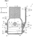
- FIG. 1 is a sectional view schematically illustrating the engine which uses an oil level detecting device 1 of one embodiment of the disclosure.
- a one-dot chain line B indicates a cylinder shaft
- a two-dot chain line C indicates a virtual plane perpendicular to the cylinder shaft B
- a reference numeral H indicates a predetermined maximum oil level
- a reference numeral L indicates a predetermined minimum oil level.
- an oil level gauge 80 is in the state of being completely inserted into a guide tube 70.
- an engine 10 includes a cylinder block 20, a crank case 30 provided in a lower end of the cylinder block 20, and an oil pan 40 provided in a lower end of the crank case 30.
- the cylinder block 20 has a cylinder part 20a and a skirt part 20b which is formed in the lower end of the cylinder part 20a.
- a piston (not illustrated) is contained to be reciprocatable inside the cylinder 20a.
- a crank shaft 11, a bearing cap 12, and the like are contained inside the skirt part 20b and the crank case 30.
- an oil chamber 50 storing engine oil O is provided inside the crank case 30 and the oil pan 40.
- the cylinder block 20 and the crank case 30 are connected by both flanges F1 and F2.
- the crank case 30 and the oil pan 40 are connected by both flanges F3 and F4.
- the flanges connected to each other are fixed to be detachable by a fastening unit such as a bolt (not illustrated) in a state where a gasket (not illustrated) is interposed between the flanges.
- the oil level detecting device 1 includes a tube insertion hole 60 which communicates with the oil chamber 50 provided in the crank case 30, the guide tube 70 fixed in the tube insertion hole 60, and the oil level gauge 80 inserted into the guide tube 70.
- a partition 35 which is formed in the crank case 30 positioned between the oil chamber 50 and the tube insertion hole 60, and a through hole 90 (air vent hole) which passes through the partition 35 to communicate the oil chamber 50 with the tube insertion hole 60 are provided.
- the tube insertion hole 60 is provided upwardly, specifically obliquely upwardly, in the crank case 30.
- the “upwardly” described above includes the “obliquely upwardly”.
- a step part 32 having a substantially triangular cross section is formed in an outer wall 31 of the crank case 30, and the tube insertion hole 60 is provided in the step part 32.
- the tube insertion hole 60 extends along a lower inclined surface 32a of the step part 32, the upper end is open outward in an upper inclined surface 32b, and the lower end is open in the crank case 30.
- the tube insertion hole 60 is formed from a position of an inner wall surface 33 of the crank case 30 toward the position of the upper inclined surface 32b of the step part 32.
- the guide tube 70 is formed by a cylindrical tube which uses a metal material or a heat resistant resin material.
- the guide tube 70 is fixed by inserting a lower end part 71 in the tube insertion hole 60, and is arranged to extend upward from the fixed position.
- the oil level gauge 80 is configured to be inserted into the guide tube 70 to be detachable from above and to seal a gap from the inner circumferential surface of the guide tube 70 in the state of being inserted into the guide tube 70.
- the oil level gauge 80 has a plate-shaped main body part 81 and a grip part 82.
- the main body part 81 is made of a metal material having an elasticity, and has a width and a thickness that enable the main body part to be inserted into the guide tube 70.
- the main body part 81 has such a length that in a state where the oil level gauge 80 is completely inserted into the guide tube 70, the tip part 81a enters the engine oil O in the oil chamber 50 to detect the oil level.
- the grip part 82 is made of a metal material or a heat resistant resin material, and has a grip part 82a and a support portion 82b supporting the main body part 81.
- the support portion 82b is inserted into the guide tube 70, so as to regulate that the grip part 82a is inserted in the opening end of the guide tube 70.
- an O ring 82c which seals a gap from the inner circumferential surface of the guide tube 70 is attached in the outer circumferential surface positioned in the center in the vertical direction of the support portion 82b.
- the partition 35 is formed to be integrated with the flange F2 of the crank case 30.
- the through hole 90 includes a first opening end 91 which is open to the oil chamber 50 and a second opening end 92 which is open to the tube insertion hole 60, and is formed to be inclined with respect to the virtual plane C perpendicular to the cylinder shaft B such that the first opening end 91 is positioned upward from the second opening end 92.
- first opening end 91 is directed toward an upper end opening part 36 of the crank case 30.
- second opening end 92 is provided to be positioned below the lower end of the guide tube 70 and above a predetermined maximum oil level H.
- FIG. 2A illustrates a state where the support portion 82b of the oil level gauge 80 starts to be inserted into the guide tube 70
- FIG. 2B illustrates a state where the support portion 82b is completely inserted into the guide tube 70.
- the oil level gauge 80 is inserted into the guide tube 70 in such a manner that the grip part 82a is held with a hand, first, the main body part 81 is inserted into the guide tube 70, and next, the support portion 82b is inserted into an upper end part 72 of the guide tube 70. In a state where the support portion 82b starts to be inserted into the guide tube 70, the O ring 82c abuts on the upper end of the guide tube 70. From the state, the O ring 82c is depressed to the position illustrated in FIG. 2B by pressing the grip part 82.
- the through hole 90 (air vent hole) is provided in the partition 35 between the oil chamber 50 and the tube insertion hole 60. Accordingly, during the insertion of the oil level gauge 80, the air inside the tube insertion hole 60 can be released to the oil chamber 50 through the through hole 90. As a result, it can be suppressed that the oil surface is lowered by the air in the tube insertion hole 60, and the oil level can be detected accurately.
- the through hole 90 can be formed with simple work that a hole is bored in the partition 35 by using a drill or the like. Therefore, for example, compared to the background art (see FIG. 3 ) that the branch pipe P is provided in the guide tube to release the air, the layout can be simplified, and an additional component is not provided necessarily. Thus, it is possible to suppress the number of the components and the production cost.
- the through hole 90 is formed such that the first opening end 91 is positioned above the second opening end 92, and is inclined with respect to the virtual plane C perpendicular to the cylinder shaft B.
- the boring work can be performed easily from above.
- the first opening end 91 is directed toward the upper end opening part 36 of the crank case 30. For this reason, the boring work can be performed easily from the wide upper end opening part 36 of the crank case 30.
- the second opening end 92 is provided to be positioned above the predetermined maximum oil level H. For this reason, even when the oil level is the maximum oil level H, the air inside the tube insertion hole 60 can be released from the second opening end 92 to the oil chamber 50.
- the plate-shaped main body part 81 made of a metal material is used in the oil level gauge 80, but an oil level gauge may be used which uses a wire-shaped main body part made of a metal material and a main body part made of a heat resistant resin.
- the oil level detecting device of the disclosure it is possible to release the air from the inside of the guide tube to the oil chamber without providing an additional component.
Landscapes
- Engineering & Computer Science (AREA)
- Mechanical Engineering (AREA)
- General Engineering & Computer Science (AREA)
- Physics & Mathematics (AREA)
- Fluid Mechanics (AREA)
- General Physics & Mathematics (AREA)
- Lubrication Details And Ventilation Of Internal Combustion Engines (AREA)
Abstract
Description
- This disclosure relates to an oil level detecting device for detecting a height position (hereinafter, referred to as an "oil level") of an oil surface of engine oil which is stored in an oil chamber in a crank case and an oil pan.
- Generally, an oil level detecting device includes a tube insertion hole which is provided in a crank case and communicates with an oil chamber, a guide tube which is inserted and fixed in the tube insertion hole, and an oil level gauge which is inserted into the guide tube in a detachable manner.
- Herein, the oil level gauge is configured to seal a gap between an inner circumferential surface of the guide tube in the state of being inserted into the guide tube.
- [Patent Literature 1]: Japanese Utility Model Application Publication No.
3-39693 - However, when the oil level gauge is inserted into the guide tube, the oil level gauge pushes the air inside the guide tube to lower the oil surface in the tube insertion hole. Thus, it is difficult to accurately detect the oil level.
- For this reason, in the background art, as illustrated in
FIG. 3 , a technique is used in which a branch pipe P is provided in aguide tube 7, and the air is released from the inside of theguide tube 7 into acylinder block 2. However, in the technique, the branch pipe P is separately provided, so that a layout becomes complicated and the number of components and a production cost are increased, which is problematic. - The disclosure has been made in consideration of the above situation and provides an oil level detecting device which can release air from an inside of a guide tube to an oil chamber without providing an additional component.
- According to this disclosure, there is provided an oil level detecting device for detecting a level of oil stored in an oil chamber in a crank case and an oil pan, the oil level detecting device includes: a tube insertion hole which is provided in the crank case upwardly and communicates with the oil chamber; a guide tube which is inserted and fixed in the tube insertion hole; an oil level gauge which is inserted into the guide tube to be detachable from above; a partition which is formed in the crank case positioned between the oil chamber and the tube insertion hole; and a through hole which passes through the partition and allows the oil chamber to communicate with the tube insertion hole.
- In the oil level detecting device, the through hole may include a first opening end which is open to the oil chamber and a second opening end which is open to the tube insertion hole, and the through hole may be formed to be inclined with respect to a virtual plane perpendicular to a cylinder shaft such that the first opening end is positioned above the second opening end.
- In the oil level detecting device, the first opening end may be directed toward an upper end opening part of the crank case.
- In the oil level detecting device, the second opening end may be provided to be positioned below the guide tube and above a predetermined maximum oil level.
- According to the oil level detecting device of this disclosure, it is possible to release the air from the inside of the guide tube to the oil chamber without providing an additional component.
-
-
FIG. 1 is a sectional view schematically illustrating a configuration of an engine which uses an oil level detecting device according to the disclosure. -
FIG. 2A is an enlarged view an A portion ofFIG. 1 , and illustrates a state where a support portion of the oil level gauge starts to be inserted into a guide tube. -
FIG. 2B is an enlarged view of the A portion ofFIG. 1 , and illustrates a state where the support portion of the oil level gauge is completely inserted into the guide tube. -
FIG. 3 is a sectional view schematically illustrating a configuration of an engine which uses an oil level detecting device of the background art. - Hereinafter, an oil level detecting device according to an embodiment of the disclosure will be described with reference to the accompanying drawings. Incidentally, as for a vertical direction (to be described) in the embodiment, a vertical direction of a vehicle mounted with an engine is set as a reference.
-
FIG. 1 is a sectional view schematically illustrating the engine which uses an oillevel detecting device 1 of one embodiment of the disclosure. In the drawings, a one-dot chain line B indicates a cylinder shaft, a two-dot chain line C indicates a virtual plane perpendicular to the cylinder shaft B, a reference numeral H indicates a predetermined maximum oil level, and a reference numeral L indicates a predetermined minimum oil level. Incidentally, in the drawings, anoil level gauge 80 is in the state of being completely inserted into aguide tube 70. - As illustrated in
FIG. 1 , anengine 10 includes acylinder block 20, acrank case 30 provided in a lower end of thecylinder block 20, and anoil pan 40 provided in a lower end of thecrank case 30. - The
cylinder block 20 has acylinder part 20a and askirt part 20b which is formed in the lower end of thecylinder part 20a. A piston (not illustrated) is contained to be reciprocatable inside thecylinder 20a. Acrank shaft 11, abearing cap 12, and the like are contained inside theskirt part 20b and thecrank case 30. In addition, anoil chamber 50 storing engine oil O is provided inside thecrank case 30 and theoil pan 40. - The
cylinder block 20 and thecrank case 30 are connected by both flanges F1 and F2. In addition, thecrank case 30 and theoil pan 40 are connected by both flanges F3 and F4. The flanges connected to each other are fixed to be detachable by a fastening unit such as a bolt (not illustrated) in a state where a gasket (not illustrated) is interposed between the flanges. - The oil
level detecting device 1 includes atube insertion hole 60 which communicates with theoil chamber 50 provided in thecrank case 30, theguide tube 70 fixed in thetube insertion hole 60, and theoil level gauge 80 inserted into theguide tube 70. In addition, in this embodiment, apartition 35 which is formed in thecrank case 30 positioned between theoil chamber 50 and thetube insertion hole 60, and a through hole 90 (air vent hole) which passes through thepartition 35 to communicate theoil chamber 50 with thetube insertion hole 60 are provided. - More specifically, the
tube insertion hole 60 is provided upwardly, specifically obliquely upwardly, in thecrank case 30. The "upwardly" described above includes the "obliquely upwardly".
Astep part 32 having a substantially triangular cross section is formed in anouter wall 31 of thecrank case 30, and thetube insertion hole 60 is provided in thestep part 32. Thetube insertion hole 60 extends along a lowerinclined surface 32a of thestep part 32, the upper end is open outward in an upperinclined surface 32b, and the lower end is open in thecrank case 30. For example, in this embodiment, thetube insertion hole 60 is formed from a position of aninner wall surface 33 of thecrank case 30 toward the position of the upperinclined surface 32b of thestep part 32. - The
guide tube 70 is formed by a cylindrical tube which uses a metal material or a heat resistant resin material. Theguide tube 70 is fixed by inserting alower end part 71 in thetube insertion hole 60, and is arranged to extend upward from the fixed position. - The
oil level gauge 80 is configured to be inserted into theguide tube 70 to be detachable from above and to seal a gap from the inner circumferential surface of theguide tube 70 in the state of being inserted into theguide tube 70. - More specifically, as illustrated in
FIGS. 2A and 2B , theoil level gauge 80 has a plate-shapedmain body part 81 and agrip part 82. - The
main body part 81 is made of a metal material having an elasticity, and has a width and a thickness that enable the main body part to be inserted into theguide tube 70. In addition, themain body part 81 has such a length that in a state where theoil level gauge 80 is completely inserted into theguide tube 70, thetip part 81a enters the engine oil O in theoil chamber 50 to detect the oil level. - The
grip part 82 is made of a metal material or a heat resistant resin material, and has agrip part 82a and asupport portion 82b supporting themain body part 81. In addition, in a state where theoil level gauge 80 is inserted into theguide tube 70, thesupport portion 82b is inserted into theguide tube 70, so as to regulate that thegrip part 82a is inserted in the opening end of theguide tube 70. In addition, anO ring 82c which seals a gap from the inner circumferential surface of theguide tube 70 is attached in the outer circumferential surface positioned in the center in the vertical direction of thesupport portion 82b. - As illustrated in
FIG. 1 , in this embodiment, thepartition 35 is formed to be integrated with the flange F2 of thecrank case 30. - The through
hole 90 includes a first openingend 91 which is open to theoil chamber 50 and a second openingend 92 which is open to thetube insertion hole 60, and is formed to be inclined with respect to the virtual plane C perpendicular to the cylinder shaft B such that the firstopening end 91 is positioned upward from the second openingend 92. - More specifically, the first opening
end 91 is directed toward an upperend opening part 36 of thecrank case 30. In addition, thesecond opening end 92 is provided to be positioned below the lower end of theguide tube 70 and above a predetermined maximum oil level H. - Next, the operational effect of the oil
level detecting device 1 of this embodiment will be described on the basis of the drawings. Herein,FIG. 2A illustrates a state where thesupport portion 82b of theoil level gauge 80 starts to be inserted into theguide tube 70, andFIG. 2B illustrates a state where thesupport portion 82b is completely inserted into theguide tube 70. - As illustrated in
FIG. 2A , theoil level gauge 80 is inserted into theguide tube 70 in such a manner that thegrip part 82a is held with a hand, first, themain body part 81 is inserted into theguide tube 70, and next, thesupport portion 82b is inserted into anupper end part 72 of theguide tube 70. In a state where thesupport portion 82b starts to be inserted into theguide tube 70, theO ring 82c abuts on the upper end of theguide tube 70. From the state, theO ring 82c is depressed to the position illustrated inFIG. 2B by pressing thegrip part 82. - At that time, if the through
hole 90 is not provided, the air in theguide tube 70 is pressed down by the movement of theO ring 82c, so that the oil surface in thetube insertion hole 60 is lowered. For this reason, it is difficult to detect the oil level accurately. - In this regard, in this embodiment, the through hole 90 (air vent hole) is provided in the
partition 35 between theoil chamber 50 and thetube insertion hole 60. Accordingly, during the insertion of theoil level gauge 80, the air inside thetube insertion hole 60 can be released to theoil chamber 50 through the throughhole 90. As a result, it can be suppressed that the oil surface is lowered by the air in thetube insertion hole 60, and the oil level can be detected accurately. - Specifically, in this embodiment, the through
hole 90 can be formed with simple work that a hole is bored in thepartition 35 by using a drill or the like. Therefore, for example, compared to the background art (seeFIG. 3 ) that the branch pipe P is provided in the guide tube to release the air, the layout can be simplified, and an additional component is not provided necessarily. Thus, it is possible to suppress the number of the components and the production cost. - In addition, the through
hole 90 is formed such that the first openingend 91 is positioned above the second openingend 92, and is inclined with respect to the virtual plane C perpendicular to the cylinder shaft B. Thus, the boring work can be performed easily from above. In addition, the first openingend 91 is directed toward the upperend opening part 36 of thecrank case 30. For this reason, the boring work can be performed easily from the wide upperend opening part 36 of thecrank case 30. - The
second opening end 92 is provided to be positioned above the predetermined maximum oil level H. For this reason, even when the oil level is the maximum oil level H, the air inside thetube insertion hole 60 can be released from the second openingend 92 to theoil chamber 50. - Incidentally, the disclosure is not limited to the above-described embodiment but may be modified as appropriate without departing from the spirit and scope of the disclosure.
- For example, in this embodiment, the plate-shaped
main body part 81 made of a metal material is used in theoil level gauge 80, but an oil level gauge may be used which uses a wire-shaped main body part made of a metal material and a main body part made of a heat resistant resin. - This application claims priority to Japanese Patent Application (
JP2015-222127), filed on November 12, 2015 - According to the oil level detecting device of the disclosure, it is possible to release the air from the inside of the guide tube to the oil chamber without providing an additional component.
-
- 1: Oil level detecting device
- 30: Crank case
- 35: Partition
- 40: Oil pan
- 50: Oil chamber
- 60: Tube insertion hole
- 70: Guide tube
- 80: Oil level gauge
- 90: Through hole
Claims (5)
- An oil level detecting device for detecting a level of oil stored in an oil chamber in a crank case and an oil pan, the oil level detecting device comprising:a tube insertion hole which is provided in the crank case upwardly and communicates with the oil chamber;a guide tube which is inserted and fixed in the tube insertion hole;an oil level gauge which is inserted into the guide tube to be detachable from above;a partition which is formed in the crank case positioned between the oil chamber and the tube insertion hole; anda through hole which passes through the partition and allows the oil chamber to communicate with the tube insertion hole.
- The oil level detecting device according to claim 1, wherein
the through hole includes a first opening end which is open to the oil chamber and a second opening end which is open to the tube insertion hole, and
the through hole is formed to be inclined with respect to a virtual plane perpendicular to a cylinder shaft such that the first opening end is positioned above the second opening end. - The oil level detecting device according to claim 2, wherein
the first opening end is directed toward an upper end opening part of the crank case. - The oil level detecting device according to claim 2, wherein
the second opening end is provided to be positioned below the guide tube and above a predetermined maximum oil level. - The oil level detecting device according to claim 3 wherein
the second opening end is provided to be positioned below the guide tube and above a predetermined maximum oil level.
Applications Claiming Priority (2)
| Application Number | Priority Date | Filing Date | Title |
|---|---|---|---|
| JP2015222127A JP2017089531A (en) | 2015-11-12 | 2015-11-12 | Oil level detection device |
| PCT/JP2016/083514 WO2017082390A1 (en) | 2015-11-12 | 2016-11-11 | Oil level detecting device |
Publications (2)
| Publication Number | Publication Date |
|---|---|
| EP3375993A1 true EP3375993A1 (en) | 2018-09-19 |
| EP3375993A4 EP3375993A4 (en) | 2019-07-10 |
Family
ID=58696125
Family Applications (1)
| Application Number | Title | Priority Date | Filing Date |
|---|---|---|---|
| EP16864351.8A Withdrawn EP3375993A4 (en) | 2015-11-12 | 2016-11-11 | Oil level detecting device |
Country Status (5)
| Country | Link |
|---|---|
| US (1) | US20180328770A1 (en) |
| EP (1) | EP3375993A4 (en) |
| JP (1) | JP2017089531A (en) |
| CN (1) | CN108350775A (en) |
| WO (1) | WO2017082390A1 (en) |
Families Citing this family (1)
| Publication number | Priority date | Publication date | Assignee | Title |
|---|---|---|---|---|
| CN108996064B (en) * | 2018-08-20 | 2020-07-28 | 中国石油工程建设有限公司 | Device for mounting limit switch |
Family Cites Families (10)
| Publication number | Priority date | Publication date | Assignee | Title |
|---|---|---|---|---|
| JPS5778712U (en) * | 1980-10-31 | 1982-05-15 | ||
| JPS612250Y2 (en) * | 1981-06-16 | 1986-01-24 | ||
| JPS58162024U (en) * | 1982-04-26 | 1983-10-28 | ヤンマーディーゼル株式会社 | Internal combustion engine lubricating oil checking device |
| JPH0339693Y2 (en) * | 1985-04-30 | 1991-08-21 | ||
| JPS62110509U (en) * | 1985-12-27 | 1987-07-14 | ||
| JPS63104615U (en) * | 1986-12-26 | 1988-07-06 | ||
| JP2002106317A (en) * | 2000-10-02 | 2002-04-10 | Mazda Motor Corp | Engine body structure |
| JP2004036437A (en) * | 2002-07-02 | 2004-02-05 | Kubota Corp | Engine oil inspection device |
| US7322232B1 (en) * | 2003-05-30 | 2008-01-29 | Sonnax Industries, Inc. | Dipstick-shielding tube and method of use |
| DE102007026369A1 (en) * | 2007-06-06 | 2008-12-11 | GM Global Technology Operations, Inc., Detroit | Device for filling of oil into inner space of machine housing, for example into oil sump of engine housing of combustion engine, has dipstick channel in which oil dipstick is extended from filling opening to oil sump of inner space |
-
2015
- 2015-11-12 JP JP2015222127A patent/JP2017089531A/en active Pending
-
2016
- 2016-11-11 WO PCT/JP2016/083514 patent/WO2017082390A1/en not_active Ceased
- 2016-11-11 EP EP16864351.8A patent/EP3375993A4/en not_active Withdrawn
- 2016-11-11 CN CN201680065850.7A patent/CN108350775A/en not_active Withdrawn
- 2016-11-11 US US15/775,330 patent/US20180328770A1/en not_active Abandoned
Also Published As
| Publication number | Publication date |
|---|---|
| WO2017082390A1 (en) | 2017-05-18 |
| EP3375993A4 (en) | 2019-07-10 |
| US20180328770A1 (en) | 2018-11-15 |
| CN108350775A (en) | 2018-07-31 |
| JP2017089531A (en) | 2017-05-25 |
Similar Documents
| Publication | Publication Date | Title |
|---|---|---|
| EP3184864A1 (en) | Sealing structure | |
| EP2662532A3 (en) | Turbine assembly with expansion seal | |
| BR112017005281A2 (en) | cover assembly that has seal inside | |
| EP3222891B1 (en) | Sealing structure | |
| EP3342978A3 (en) | Integrated squealer pocket tip and tip shelf with hybrid and tip flag core | |
| RU2019101043A (en) | BOB WITH INNER BEARING | |
| US20170261062A1 (en) | End Cap For A Piston-Cylinder Unit | |
| ATE483546T1 (en) | COVER FOR WELDING A WIRE CONTAINER | |
| BR112018000117A2 (en) | metal bushing cap, metal bushing cap used in combination with a metal bottle, and method for manufacturing a metal bushing cap | |
| US20120279386A1 (en) | Hydraulic support element | |
| US20180328770A1 (en) | Oil level detecting device | |
| CN103307405B (en) | Sealing device and method | |
| EP2918861A3 (en) | Cage bearing with oil retaining shield | |
| RU2018106366A (en) | CONTAINER AND LID | |
| EP3348496A3 (en) | Seal assembly system, bag | |
| US20160200284A1 (en) | High-pressure gas cylinder | |
| EP3244014A3 (en) | Retaining ring | |
| EP3712382A3 (en) | Blade outer air seal with wear liner | |
| NO20181413A1 (en) | Drilling head with non-rotating annular seal assembly | |
| EP3306195A3 (en) | Wall panel assembly for a gas turbine engine | |
| EP3447247A3 (en) | Damped fluid transfer tube for a gas turbine engine | |
| CN207987993U (en) | A kind of spigot-and-socket sound detecting pipe | |
| CL2020001469A1 (en) | Clamping device for a lifting cable of a lifting device. | |
| CN204942288U (en) | A kind of overall punching type deep groove ball bearing retainer | |
| KR100783547B1 (en) | Drain plug for oil pan |
Legal Events
| Date | Code | Title | Description |
|---|---|---|---|
| PUAI | Public reference made under article 153(3) epc to a published international application that has entered the european phase |
Free format text: ORIGINAL CODE: 0009012 |
|
| 17P | Request for examination filed |
Effective date: 20180612 |
|
| AK | Designated contracting states |
Kind code of ref document: A1 Designated state(s): AL AT BE BG CH CY CZ DE DK EE ES FI FR GB GR HR HU IE IS IT LI LT LU LV MC MK MT NL NO PL PT RO RS SE SI SK SM TR |
|
| AX | Request for extension of the european patent |
Extension state: BA ME |
|
| DAV | Request for validation of the european patent (deleted) | ||
| DAX | Request for extension of the european patent (deleted) | ||
| A4 | Supplementary search report drawn up and despatched |
Effective date: 20190607 |
|
| RIC1 | Information provided on ipc code assigned before grant |
Ipc: F01M 11/12 20060101AFI20190603BHEP Ipc: G01F 23/04 20060101ALI20190603BHEP |
|
| STAA | Information on the status of an ep patent application or granted ep patent |
Free format text: STATUS: THE APPLICATION HAS BEEN WITHDRAWN |
|
| 18W | Application withdrawn |
Effective date: 20191023 |