EP3375661A1 - Cft pre-forming insert injection molded seat back frame - Google Patents
Cft pre-forming insert injection molded seat back frame Download PDFInfo
- Publication number
- EP3375661A1 EP3375661A1 EP16864619.8A EP16864619A EP3375661A1 EP 3375661 A1 EP3375661 A1 EP 3375661A1 EP 16864619 A EP16864619 A EP 16864619A EP 3375661 A1 EP3375661 A1 EP 3375661A1
- Authority
- EP
- European Patent Office
- Prior art keywords
- back frame
- reinforcement
- forming
- seat back
- cft
- Prior art date
- Legal status (The legal status is an assumption and is not a legal conclusion. Google has not performed a legal analysis and makes no representation as to the accuracy of the status listed.)
- Granted
Links
Images






Classifications
-
- B—PERFORMING OPERATIONS; TRANSPORTING
- B29—WORKING OF PLASTICS; WORKING OF SUBSTANCES IN A PLASTIC STATE IN GENERAL
- B29C—SHAPING OR JOINING OF PLASTICS; SHAPING OF MATERIAL IN A PLASTIC STATE, NOT OTHERWISE PROVIDED FOR; AFTER-TREATMENT OF THE SHAPED PRODUCTS, e.g. REPAIRING
- B29C45/00—Injection moulding, i.e. forcing the required volume of moulding material through a nozzle into a closed mould; Apparatus therefor
- B29C45/14—Injection moulding, i.e. forcing the required volume of moulding material through a nozzle into a closed mould; Apparatus therefor incorporating preformed parts or layers, e.g. injection moulding around inserts or for coating articles
- B29C45/14778—Injection moulding, i.e. forcing the required volume of moulding material through a nozzle into a closed mould; Apparatus therefor incorporating preformed parts or layers, e.g. injection moulding around inserts or for coating articles the article consisting of a material with particular properties, e.g. porous, brittle
- B29C45/14786—Fibrous material or fibre containing material, e.g. fibre mats or fibre reinforced material
-
- B—PERFORMING OPERATIONS; TRANSPORTING
- B29—WORKING OF PLASTICS; WORKING OF SUBSTANCES IN A PLASTIC STATE IN GENERAL
- B29C—SHAPING OR JOINING OF PLASTICS; SHAPING OF MATERIAL IN A PLASTIC STATE, NOT OTHERWISE PROVIDED FOR; AFTER-TREATMENT OF THE SHAPED PRODUCTS, e.g. REPAIRING
- B29C45/00—Injection moulding, i.e. forcing the required volume of moulding material through a nozzle into a closed mould; Apparatus therefor
- B29C45/14—Injection moulding, i.e. forcing the required volume of moulding material through a nozzle into a closed mould; Apparatus therefor incorporating preformed parts or layers, e.g. injection moulding around inserts or for coating articles
- B29C45/1418—Injection moulding, i.e. forcing the required volume of moulding material through a nozzle into a closed mould; Apparatus therefor incorporating preformed parts or layers, e.g. injection moulding around inserts or for coating articles the inserts being deformed or preformed, e.g. by the injection pressure
- B29C45/14221—Injection moulding, i.e. forcing the required volume of moulding material through a nozzle into a closed mould; Apparatus therefor incorporating preformed parts or layers, e.g. injection moulding around inserts or for coating articles the inserts being deformed or preformed, e.g. by the injection pressure by tools, e.g. cutting means
-
- B—PERFORMING OPERATIONS; TRANSPORTING
- B29—WORKING OF PLASTICS; WORKING OF SUBSTANCES IN A PLASTIC STATE IN GENERAL
- B29C—SHAPING OR JOINING OF PLASTICS; SHAPING OF MATERIAL IN A PLASTIC STATE, NOT OTHERWISE PROVIDED FOR; AFTER-TREATMENT OF THE SHAPED PRODUCTS, e.g. REPAIRING
- B29C70/00—Shaping composites, i.e. plastics material comprising reinforcements, fillers or preformed parts, e.g. inserts
- B29C70/04—Shaping composites, i.e. plastics material comprising reinforcements, fillers or preformed parts, e.g. inserts comprising reinforcements only, e.g. self-reinforcing plastics
- B29C70/06—Fibrous reinforcements only
- B29C70/10—Fibrous reinforcements only characterised by the structure of fibrous reinforcements, e.g. hollow fibres
- B29C70/16—Fibrous reinforcements only characterised by the structure of fibrous reinforcements, e.g. hollow fibres using fibres of substantial or continuous length
- B29C70/20—Fibrous reinforcements only characterised by the structure of fibrous reinforcements, e.g. hollow fibres using fibres of substantial or continuous length oriented in a single direction, e.g. roofing or other parallel fibres
-
- B—PERFORMING OPERATIONS; TRANSPORTING
- B29—WORKING OF PLASTICS; WORKING OF SUBSTANCES IN A PLASTIC STATE IN GENERAL
- B29D—PRODUCING PARTICULAR ARTICLES FROM PLASTICS OR FROM SUBSTANCES IN A PLASTIC STATE
- B29D99/00—Subject matter not provided for in other groups of this subclass
- B29D99/0092—Producing upholstery articles, e.g. cushions, seats
-
- B—PERFORMING OPERATIONS; TRANSPORTING
- B60—VEHICLES IN GENERAL
- B60N—SEATS SPECIALLY ADAPTED FOR VEHICLES; VEHICLE PASSENGER ACCOMMODATION NOT OTHERWISE PROVIDED FOR
- B60N2/00—Seats specially adapted for vehicles; Arrangement or mounting of seats in vehicles
- B60N2/68—Seat frames
-
- B—PERFORMING OPERATIONS; TRANSPORTING
- B60—VEHICLES IN GENERAL
- B60N—SEATS SPECIALLY ADAPTED FOR VEHICLES; VEHICLE PASSENGER ACCOMMODATION NOT OTHERWISE PROVIDED FOR
- B60N2/00—Seats specially adapted for vehicles; Arrangement or mounting of seats in vehicles
- B60N2/68—Seat frames
- B60N2/686—Panel like structures
-
- B—PERFORMING OPERATIONS; TRANSPORTING
- B29—WORKING OF PLASTICS; WORKING OF SUBSTANCES IN A PLASTIC STATE IN GENERAL
- B29C—SHAPING OR JOINING OF PLASTICS; SHAPING OF MATERIAL IN A PLASTIC STATE, NOT OTHERWISE PROVIDED FOR; AFTER-TREATMENT OF THE SHAPED PRODUCTS, e.g. REPAIRING
- B29C45/00—Injection moulding, i.e. forcing the required volume of moulding material through a nozzle into a closed mould; Apparatus therefor
- B29C45/14—Injection moulding, i.e. forcing the required volume of moulding material through a nozzle into a closed mould; Apparatus therefor incorporating preformed parts or layers, e.g. injection moulding around inserts or for coating articles
- B29C45/1418—Injection moulding, i.e. forcing the required volume of moulding material through a nozzle into a closed mould; Apparatus therefor incorporating preformed parts or layers, e.g. injection moulding around inserts or for coating articles the inserts being deformed or preformed, e.g. by the injection pressure
- B29C2045/14237—Injection moulding, i.e. forcing the required volume of moulding material through a nozzle into a closed mould; Apparatus therefor incorporating preformed parts or layers, e.g. injection moulding around inserts or for coating articles the inserts being deformed or preformed, e.g. by the injection pressure the inserts being deformed or preformed outside the mould or mould cavity
- B29C2045/14245—Injection moulding, i.e. forcing the required volume of moulding material through a nozzle into a closed mould; Apparatus therefor incorporating preformed parts or layers, e.g. injection moulding around inserts or for coating articles the inserts being deformed or preformed, e.g. by the injection pressure the inserts being deformed or preformed outside the mould or mould cavity using deforming or preforming means outside the mould cavity
-
- B—PERFORMING OPERATIONS; TRANSPORTING
- B29—WORKING OF PLASTICS; WORKING OF SUBSTANCES IN A PLASTIC STATE IN GENERAL
- B29C—SHAPING OR JOINING OF PLASTICS; SHAPING OF MATERIAL IN A PLASTIC STATE, NOT OTHERWISE PROVIDED FOR; AFTER-TREATMENT OF THE SHAPED PRODUCTS, e.g. REPAIRING
- B29C2791/00—Shaping characteristics in general
- B29C2791/001—Shaping in several steps
-
- B—PERFORMING OPERATIONS; TRANSPORTING
- B29—WORKING OF PLASTICS; WORKING OF SUBSTANCES IN A PLASTIC STATE IN GENERAL
- B29L—INDEXING SCHEME ASSOCIATED WITH SUBCLASS B29C, RELATING TO PARTICULAR ARTICLES
- B29L2031/00—Other particular articles
- B29L2031/771—Seats
Definitions
- the present invention relates to a seat back frame, and more particularly, to a CFT pre-forming insert injection molded seat back frame capable of securing the strength and the rigidity by constituting a plurality of ribs in a structure shape and a frame itself.
- a seat back of a vehicle is a means for providing a comfortable and easy boarding environment by supporting a passenger's back by being connected to a seat cushion for supporting a passenger's hips.
- Such a seat back is usually molded to a plastic material, and forms a rib or a channel on the rod-reinforced seat back frame to maintain the strength.
- the steel reinforcement bracket or a plate-like reinforcement material such as a steel type is used to further reinforce the strength
- the weight is sharply increased, and thus, it has the disadvantage unfavorable in terms of competitiveness and is highly unfavorable in terms of rigidity.
- the seat back frame was compression-molded having GMT (Glass Mat Thermoplastics) and LFT (Long Fiber reinforced Thermoplastics) as the material to secure the rigidity due to the collision.
- GMT Glass Mat Thermoplastics
- LFT Long Fiber reinforced Thermoplastics
- the seat back frame thus formed largely consists of a front frame and a back frame.
- the rib is not formed on the backside of the conventional front frame and is formed to have a flat plate shape.
- the rib is manufactured to be formed on the front side of the back frame coupled with the backside of the front frame.
- the back frame serves as a main frame and the front frame serves as an auxiliary frame.
- Another object of the present invention is to provide a CFT pre-forming insert injection molded sheet back frame to increase the strength and the rigidity by molding the plurality of ribs through the injection molding, after pre-forming molding the continuous fiber reinforced thermoplastic.
- the present invention provides a CFT pre-forming insert injection molded seat back frame.
- the seat back frame includes a pair of frame parts which are coupled to face each other and the fiber reinforced plastic is formed therein; and reinforcement parts which are formed on the region respectively face of the pair of frames and are coupled each other in multiple locations.
- the pair of the frame parts includes the front frame which the first coupling region is formed on one surface and the back frame which the second coupling region facing with the first coupling region on one surface is formed.
- the opposed region includes the first coupling region and the second coupling region.
- the reinforcement parts have a plurality of first reinforcement ribs which are protrusion-formed on the first coupling region and a plurality of second reinforcement ribs which are protrusion-formed on the second coupling region coupled with the plurality of first reinforcement ribs.
- the plurality of first reinforcement ribs and the plurality of second reinforcement ribs are formed to be symmetrical to each other.
- the plurality of first reinforcement ribs and the plurality of second reinforcement ribs are coupled to each other by mechanical fastening using a fusion or a fastening bolt.
- the plurality of first reinforcement ribs and the plurality of second reinforcement ribs may be coupled by fitted to each other.
- the fiber reinforcement plastic is formed inside the reinforcement parts.
- the pair of the frame parts may be manufactured by forming to the pre-forming molding having the pre-forming shape by pressing it in order to have the predetermined shape through the pre-forming molding and by injection molding the pre-forming molding by using the other thermoplastic while simultaneously forming the reinforcement parts.
- the pair of the frame parts may be also manufactured by forming the pre-forming which the reinforcement parts are formed by pressing it in order to have the determined shape through the pre-forming molding and injection molding the pre-forming molding by using the other thermoplastic.
- the CFT pre-forming insert injection molded seat back frame of the present invention may include a pair of frame parts including a front frame coupled to face each other, and a back frame coupled to the front frame; and reinforcement parts including a plurality of first reinforcement ribs formed on the front frame.
- the first reinforcement ribs are protrusion formed on the first coupling region formed on the front frame.
- the present invention has the effect of securing its own strength and rigidity by forming a plurality of ribs symmetrical to each other on the coupling surfaces of each of a pair of frames which are coupled to face each other.
- the present invention has the effect of increasing the strength and rigidity of the frame through the shape consisting of a plurality of ribs through injection molding after pre-forming molding the continuous fiber reinforced thermoplastic.
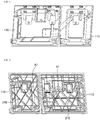
- FIG. 1 is a view showing a front side a front frame according to the present invention
- FIG. 2 is a view showing a rear side of a front frame according to the present invention
- FIG. 3 is a view showing a front side of a back frame according to the present invention
- FIG.4 is a view showing a rear side of a back frame according to the present invention.
- the hatchback seat back frame according to the present invention may be consisted of a two-row or three-row seat of a vehicle
- the seat back frame of the present invention is constituted of a pair of the frame parts 100 and reinforcement parts 200.
- the pair of frame parts 100 is constituted of a front frame 110 and a back frame 120.
- a structure having a predetermined shape is protrusion formed on the front side of the front frame 110.
- a first coupling area A1 is formed on a rear side of the front frame 110.
- a second engagement region A2 is formed on the front side of the back frame 120, and a backside thereof is formed in a flat plate shape.
- first coupling region A1 and the second coupling region A2 are arranged to face each other.
- the reinforcement parts 200 are formed in a facing area of each of the pair of frame parts 100 and are coupled to each other in multiple locations.
- the facing regions are the first and second coupling regions A1 and A2 described above.
- the reinforcement parts 200 are constituted of a plurality of first reinforcement ribs 210 and a plurality of second reinforcement ribs 220.
- the plurality of first reinforcement ribs 210 are formed to be protruded at the first coupled region A1 of the front frame 110.
- the plurality of second reinforcement ribs 220 are formed to be protruded at the second coupling region A2 of the back frame 120.
- the plurality of first and second reinforcement ribs 210 and 220 are formed to have the same pattern.
- the front frame 110 and the back frame 120 when the front frame 110 and the back frame 120 are coupled to face each other, they have the predetermined height from the bottom surface of the corresponding coupling region of the corresponding frame such that the ends of the plurality of first and second reinforcement ribs 210, 220 are adhered to each other.
- FIG. 5 is a perspective view showing a state in which a front frame and a back frame are combined according to the present invention.
- the front frame 110 and the back frame 120 according to the present invention are coupled such that the first and second coupled regions A1 and A2 face each other.
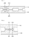
- FIG. 6 is a partial cross-sectional view showing an example in which a plurality of first and second reinforcement ribs according to the present invention are coupled through the fusion.
- the ends of the first and second reinforcement ribs 210 and 220 are adhesion coupled, by coupled through a vibration fusion, an IR fusion, a vibration fusion, and a heat fusion.
- FIG. 7 is a partial cross-sectional view showing an example in which a plurality of first and second reinforcement ribs according to the present invention are coupled through the mechanical fastening.
- the ends of the first and second reinforcement ribs 210 and 220 are disposed in a state adhere to each other.
- first and second reinforcement ribs 210 and 220 also may be mechanically coupled in multiple locations through a fastening member 230 such as a separate fastening bolt.
- FIGS. 8 and 9 are partial cross-sectional views showing an example in which a plurality of first and second reinforcement ribs according to the present invention are coupled through fitting coupling.
- first and second reinforcement ribs 210 and 220 may be coupled to each other by fitting coupling.
- a fitting protrusion 211 protruding at an end of the first reinforcement rib 210 is formed, and a fitting groove 221 is formed at an end of the second reinforcement rib 220.
- the pointed protrusion 212 is formed downward at the end of the first reinforcement rib 210 and the grooves 222 at which the pointed protrusion 212 is fitted at the ends of the second reinforcement ribs 220 may be also formed.
- the pointed protrusion 212 may be coupled by being fitted into the groove 222.
- a mechanical coupling may be performed using a separate fastening member (see FIG. 6 ).
- the normal coupling may be a state in which the ends of the first and second reinforcement ribs 210 and 220 are coupled in a state being not distorted from each other.
- FIG. 10 is a sectional view showing a modified example of the coupled location of the first and second reinforcement ribs according to the present invention.
- the end locations of the first reinforcement ribs 210 may be formed differently from each other. Also, the locations of the second reinforcement ribs 220 may be also formed differently from each other so as to be adhered with the ends of the first reinforcement rib.
- the position is a coupling location of the ends of the first and second reinforcement ribs 210 and 220, and accordingly, the protruded lengths of the first and second reinforcement ribs 210 and 220 may be formed differently from each other.
- the overall coupled location may be formed in a shape that forms the zig-zag along the width direction or the longitudinal direction of the frame part 100.
- the distortion to the lateral direction may be further efficiently prevented, by forming the length thereof differently such that the zig-zag shape is formed at the ends of the first and second reinforcement fibs 210, 220 which the coupling site between the front frame 110 and the back frame 120.
- FIG. 11 is a flow chart showing a method of manufacturing a CFT pre-forming insert injection molded sheet back frame according to the present invention
- FIG. 12 is a view showing a pre-forming molding step according to the present invention
- FIG. 13 is a view showing an injection molding step according to the present invention.
- the CFT pre-forming insert injection molded sheet back frame of the present invention is manufactured through a pre-forming molding step to an injection molding step.
- the reference numerals of the CFT pre-forming insert injection molded seat back frame of the present invention will be described with reference to FIGS. 1 to 10 .
- a continuous fiber reinforced thermoplastic (CFT) and a pre-forming molding die 10 which is a press molding apparatus for molding a predetermined shape, are prepared.
- the pre-forming molding mold may be classified into an upper mold and a lower mold.
- the continuous fiber reinforced thermoplastics (CFT) prepared is placed between the upper and lower molds.
- the pre-forming molding 20 by coupling the upper mold and the lower mold and pressing the continuous fiber reinforced thermoplastic (CFT) to have the predetermined shape.
- CFT continuous fiber reinforced thermoplastic
- the pre-forming mold 20 is preheated to a determined temperature.
- the injection material is input into the injector 30 and injection molded.
- the injection material may be used by including any one or at least one or more of the long fiber and short fiber reinforced thermoplastics.
- the long fiber reinforced thermoplastic resin is formed to have a predetermined on the outer surface of the preform 20 through am injection molding, and at this time, the reinforcement part 200, that is, the first reinforcement rib 210 or the second reinforcement rib 220 is also formed simultaneously, so that the frame part 100 and the reinforcement part 200 are manufactured.
- the continuous fiber reinforced thermoplastic (CFT) is embedded in the inside of the seat back frame, so that its own strength and rigidity can be secured.
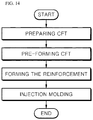
- FIG. 14 is a flow chart showing another method of manufacturing the seat back frame of the present invention.
- the reinforcement part 200 according to the present invention may be also formed in the pre-forming molding step.
- the pre-forming molding 20 is formed which the reinforcement parts 200 are formed by applying it to be the determined shape through the pre-forming.
- a shape of molding the reinforcement parts 200 is prepared in advance.
- the pre-forming molding 20 is injection molded using the LFT to produce a seat back frame.
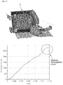
- FIG. 15 is a view showing an analytical shape and a displacement amount measurement result of a seat back frame according to a Comparative Example
- FIG. 16 is a view showing an analytical shape and a displacement amount measurement result of a seat back frame according to the Embodiment 1
- FIG. 17 is a view showing an analytical shape and a displacement amount measurement result of a seat back frame according to the second embodiment.
- Embodiment 1 is a case in which the reinforcement ribs are formed in both of the front frame and the back frame
- Embodiment 2 shows the analytical shape and the displacement amount measurement result in the case where the reinforcement rib is formed only in the front frame.
- Embodiments 1 and 2 have a pair of frame parts and reinforcement parts according to the present invention.
- the comparative example it is the constitution of forming the flat plate shape that the separate reinforcement rib is not existed in the front frame and the reinforcement rib is formed only in the back frame.
- Embodiment 1 the reinforcement rib is formed in both the front frame and the back frame
- Embodiment 2 shows a case in which the compensation rib is formed only in the front frame.
- test conditions are as follows.
- a load of 2 tons is applied forward to the seat back frame (1,2,2 ') of each of the Comparative Example and Embodiments 1 and 2.
- the amount of displacement is measured with the state before the load of 2 tons forward is applied to the seat back frame (1, 2) of each of the Comparative Example and Embodiments 1 and 2, as a zero point.
- the maximum displacement amount of the seat back frame 1 was measured to be 325 mm, and the maximum displacement amount of the seat back frame 2 of Example 1 was measured to be 275 mm.
- the maximum displacement thereof of the seat back frame of Embodiment 2 shown in Fig. 17 is measured to be 289 mm.
- Example 1 it is shown that the displacement amount of 50 mm is smaller compared to the Comparative Example.
- a plurality of ribs symmetrical to each other can be formed on the coupling surfaces of each of a pair of frames which are coupled to face each other, thereby securing its own strength and rigidity.
- the present invention has an advantage of reducing the manufacturing cost while increasing the rigidity.
Landscapes
- Engineering & Computer Science (AREA)
- Mechanical Engineering (AREA)
- Manufacturing & Machinery (AREA)
- Aviation & Aerospace Engineering (AREA)
- Transportation (AREA)
- Chemical & Material Sciences (AREA)
- Composite Materials (AREA)
- Textile Engineering (AREA)
- Seats For Vehicles (AREA)
- Chair Legs, Seat Parts, And Backrests (AREA)
- Injection Moulding Of Plastics Or The Like (AREA)
Description
- The present invention relates to a seat back frame, and more particularly, to a CFT pre-forming insert injection molded seat back frame capable of securing the strength and the rigidity by constituting a plurality of ribs in a structure shape and a frame itself.
- Generally, a seat back of a vehicle is a means for providing a comfortable and easy boarding environment by supporting a passenger's back by being connected to a seat cushion for supporting a passenger's hips.
- Such a seat back is usually molded to a plastic material, and forms a rib or a channel on the rod-reinforced seat back frame to maintain the strength.
- In addition, although there is an example that the steel reinforcement bracket or a plate-like reinforcement material, such as a steel type is used to further reinforce the strength, in this case, the weight is sharply increased, and thus, it has the disadvantage unfavorable in terms of competitiveness and is highly unfavorable in terms of rigidity.
- Particularly, in the case of a two-row seat back frame of a passenger vehicle or a three-row seat back frame of a people carrier, due to an external collision, it may directly collide with the luggage loaded on the trunk, and the frame itself may be broken.
- Conventionally, the seat back frame was compression-molded having GMT (Glass Mat Thermoplastics) and LFT (Long Fiber reinforced Thermoplastics) as the material to secure the rigidity due to the collision.
- The seat back frame thus formed largely consists of a front frame and a back frame.
- The rib is not formed on the backside of the conventional front frame and is formed to have a flat plate shape.
- Further, the rib is manufactured to be formed on the front side of the back frame coupled with the backside of the front frame.
- The back frame serves as a main frame and the front frame serves as an auxiliary frame.
- Accordingly, there is a problem that the front frame is easily broken when the seat back frame directly collides with the luggage loaded on the trunk due to an external collision, due to the elimination of the rib for reinforcement at the front frame.
- Prior art related to the present invention is Korean Patent Laid-Open Patent Publication No.
10-2013-0014854 (published date: February 12, 2013 - It is an object of the present invention to provide a CFT pre-forming insert injection molded seat back frame which can secure its own strength and rigidity by forming a plurality of ribs symmetrical to each other on a coupling surface of each of a pair of frames.
- Another object of the present invention is to provide a CFT pre-forming insert injection molded sheet back frame to increase the strength and the rigidity by molding the plurality of ribs through the injection molding, after pre-forming molding the continuous fiber reinforced thermoplastic.
- It is a another object of the present invention to provide a CFT pre-forming insert injection molded sheet back frame which the front frame serves as the main frame and has the shape such as a center mounting part, a side mounting part, and a headrest mounting part which are connected with the vehicle body as well as the rib, and the back frame has the plurality of ribs as the auxiliary frame function.
- In a preferred aspect, the present invention provides a CFT pre-forming insert injection molded seat back frame.
- The seat back frame includes a pair of frame parts which are coupled to face each other and the fiber reinforced plastic is formed therein; and reinforcement parts which are formed on the region respectively face of the pair of frames and are coupled each other in multiple locations.
- It is preferable that the pair of the frame parts includes the front frame which the first coupling region is formed on one surface and the back frame which the second coupling region facing with the first coupling region on one surface is formed.
- It is preferable that the opposed region includes the first coupling region and the second coupling region.
- It is preferable that the reinforcement parts have a plurality of first reinforcement ribs which are protrusion-formed on the first coupling region and a plurality of second reinforcement ribs which are protrusion-formed on the second coupling region coupled with the plurality of first reinforcement ribs.
- It is preferable that the plurality of first reinforcement ribs and the plurality of second reinforcement ribs are formed to be symmetrical to each other.
- It is preferable that the plurality of first reinforcement ribs and the plurality of second reinforcement ribs are coupled to each other by mechanical fastening using a fusion or a fastening bolt.
- The plurality of first reinforcement ribs and the plurality of second reinforcement ribs may be coupled by fitted to each other.
- It is preferable that the fiber reinforcement plastic is formed inside the reinforcement parts.
- It is preferable that the pair of the frame parts may be manufactured by forming to the pre-forming molding having the pre-forming shape by pressing it in order to have the predetermined shape through the pre-forming molding and by injection molding the pre-forming molding by using the other thermoplastic while simultaneously forming the reinforcement parts.
- The pair of the frame parts may be also manufactured by forming the pre-forming which the reinforcement parts are formed by pressing it in order to have the determined shape through the pre-forming molding and injection molding the pre-forming molding by using the other thermoplastic.
- Also, the CFT pre-forming insert injection molded seat back frame of the present invention may include a pair of frame parts including a front frame coupled to face each other, and a back frame coupled to the front frame; and reinforcement parts including a plurality of first reinforcement ribs formed on the front frame.
- Here, it is preferable that the first reinforcement ribs are protrusion formed on the first coupling region formed on the front frame.
- The present invention has the effect of securing its own strength and rigidity by forming a plurality of ribs symmetrical to each other on the coupling surfaces of each of a pair of frames which are coupled to face each other.
- Also, the present invention has the effect of increasing the strength and rigidity of the frame through the shape consisting of a plurality of ribs through injection molding after pre-forming molding the continuous fiber reinforced thermoplastic.
-
-
FIG. 1 is a view showing a front side of the front frame according to the present invention. -
FIG. 2 is a view of showing a rear side of the front frame according to the present invention. -
FIG. 3 is a view of showing a front side of the back frame according to the present invention. -
FIG. 4 is a view of showing a rear side of the back frame according to the present invention. -
FIG. 5 is a perspective view of showing a state that the front frame and the back frame are couplied according to the present invention. -
FIG. 6 is a partial cross-sectional view showing an example in which a plurality of first and second reinforcement leads according to the present invention are coupled through the fusion. -
FIG. 7 is a partial cross-sectional view showing an example in which a plurality of first and second reinforcement ribs according to the present invention are coupled through the mechanical fastening. -
FIGS. 8 and9 are the partial cross-sectional views showing an example in which a plurality of first and second reinforcing ribs according to the present invention are coupled through mechanical fitting. -
FIG. 10 is a sectional view showing a modified example of the coupling location of the first and second reinforcement ribs according to the present invention. -
FIG. 11 is a flow chart showing a method of manufacturing a CFT pre-forming insert injection molded sheet back frame of the present invention. -
FIG. 12 is a view showing a pre-forming molding step according to the present invention. -
FIG. 13 is a view showing an injection molding step according to the present invention. -
FIG. 14 is a flow chart showing another method of manufacturing the CFT pre-forming insert injection molded seat back frame of the present invention. -
Fig. 15 is a view showing an analytical shape of a seat back frame and a displacement amount measurement result according to a Comparative Example. -
FIG. 16 is a view showing the analytical shape of the seat back frame and the measurement result of the displacement amount according toEmbodiment 1. -
FIG. 17 is a view showing the analytical shape of the seat back frame and the measurement results of the displacement amount according toEmbodiment 2. - Hereinafter, a CFT pre-forming insert injection molded sheet back frame according to the present invention will be described with reference to the accompanying drawings.
-
FIG. 1 is a view showing a front side a front frame according to the present invention,FIG. 2 is a view showing a rear side of a front frame according to the present invention,FIG. 3 is a view showing a front side of a back frame according to the present invention, andFIG.4 is a view showing a rear side of a back frame according to the present invention. - With reference to
FIGS. 1 to 4 , afront frame 110 and aback frame 120 constituting the CFT pre-forming insert injection molded seat back frame of the present invention will be described. - The hatchback seat back frame according to the present invention may be consisted of a two-row or three-row seat of a vehicle
- The seat back frame of the present invention is constituted of a pair of the
frame parts 100 andreinforcement parts 200. - The pair of
frame parts 100 is constituted of afront frame 110 and aback frame 120. - As shown in
FIG. 1 , a structure having a predetermined shape is protrusion formed on the front side of thefront frame 110. - Referring to
FIG. 2 , a first coupling area A1 is formed on a rear side of thefront frame 110. - Also, a second engagement region A2 is formed on the front side of the
back frame 120, and a backside thereof is formed in a flat plate shape. - Here, the first coupling region A1 and the second coupling region A2 are arranged to face each other.
- The
reinforcement parts 200 are formed in a facing area of each of the pair offrame parts 100 and are coupled to each other in multiple locations. - The facing regions are the first and second coupling regions A1 and A2 described above.
- The
reinforcement parts 200 are constituted of a plurality offirst reinforcement ribs 210 and a plurality ofsecond reinforcement ribs 220. - The plurality of
first reinforcement ribs 210 are formed to be protruded at the first coupled region A1 of thefront frame 110. - Also, the plurality of
second reinforcement ribs 220 are formed to be protruded at the second coupling region A2 of theback frame 120. - Here, the plurality of first and
second reinforcement ribs - Preferably, when the
front frame 110 and theback frame 120 are coupled to face each other, they have the predetermined height from the bottom surface of the corresponding coupling region of the corresponding frame such that the ends of the plurality of first andsecond reinforcement ribs -
FIG. 5 is a perspective view showing a state in which a front frame and a back frame are combined according to the present invention. - The
front frame 110 and theback frame 120 according to the present invention are coupled such that the first and second coupled regions A1 and A2 face each other. - At this time, the ends of the plurality of
first reinforcement ribs 210 and the plurality ofsecond reinforcement ribs 220 are in a state adhered to each other. - The following describes the coupling relationship of the plurality of first and second reinforcing
ribs -
FIG. 6 is a partial cross-sectional view showing an example in which a plurality of first and second reinforcement ribs according to the present invention are coupled through the fusion. - Referring to
FIG. 6 , the ends of the first andsecond reinforcement ribs -
FIG. 7 is a partial cross-sectional view showing an example in which a plurality of first and second reinforcement ribs according to the present invention are coupled through the mechanical fastening. - Referring to
FIG. 7 , the ends of the first andsecond reinforcement ribs - Next, the first and
second reinforcement ribs fastening member 230 such as a separate fastening bolt. -
FIGS. 8 and9 are partial cross-sectional views showing an example in which a plurality of first and second reinforcement ribs according to the present invention are coupled through fitting coupling. - Also, referring to
FIGS. 8 and9 , the first andsecond reinforcement ribs - In case of
FIG. 8 , afitting protrusion 211 protruding at an end of thefirst reinforcement rib 210 is formed, and afitting groove 221 is formed at an end of thesecond reinforcement rib 220. - Therefore, when the
front frame 110 and theback frame 120 are coupled to each other, the first andsecond reinforcement ribs fitting protrusion 211 is coupled to being fitted into thefitting groove 221 - In addition, in case of
FIG. 9 , thepointed protrusion 212 is formed downward at the end of thefirst reinforcement rib 210 and thegrooves 222 at which the pointedprotrusion 212 is fitted at the ends of thesecond reinforcement ribs 220 may be also formed. - Therefore, when the
front frame 110 and theback frame 120 are coupled to each other, as the first andsecond reinforcement ribs pointed protrusion 212 may be coupled by being fitted into thegroove 222. - Of course, as in
FIGS. 8 and9 , after the first andsecond reinforcement ribs FIG. 6 ). - In particular, in the case of
FIG. 9 , there is an advantage of positioning that thepointed protrusion 212 is inserted into thepointed groove 212 to guide the first andsecond reinforcement ribs - The normal coupling may be a state in which the ends of the first and
second reinforcement ribs -
FIG. 10 is a sectional view showing a modified example of the coupled location of the first and second reinforcement ribs according to the present invention. - Referring to
FIG. 10 , the end locations of thefirst reinforcement ribs 210 may be formed differently from each other. Also, the locations of thesecond reinforcement ribs 220 may be also formed differently from each other so as to be adhered with the ends of the first reinforcement rib. - Here, the position is a coupling location of the ends of the first and
second reinforcement ribs second reinforcement ribs - The overall coupled location may be formed in a shape that forms the zig-zag along the width direction or the longitudinal direction of the
frame part 100. - According to the configuration thereof, when an impact is applied to the
frame part 100 coupled to each other, the distortion to the lateral direction may be further efficiently prevented, by forming the length thereof differently such that the zig-zag shape is formed at the ends of the first and second reinforcement fibs 210, 220 which the coupling site between thefront frame 110 and theback frame 120. - Next, a method of manufacturing the seat back frame of the present invention will be described.
-
FIG. 11 is a flow chart showing a method of manufacturing a CFT pre-forming insert injection molded sheet back frame according to the present invention,FIG. 12 is a view showing a pre-forming molding step according to the present invention, andFIG. 13 is a view showing an injection molding step according to the present invention. - Referring to
FIG. 11 , the CFT pre-forming insert injection molded sheet back frame of the present invention is manufactured through a pre-forming molding step to an injection molding step. The reference numerals of the CFT pre-forming insert injection molded seat back frame of the present invention will be described with reference toFIGS. 1 to 10 . - Referring to
FIGS. 11 and12 , a continuous fiber reinforced thermoplastic (CFT) and a pre-forming molding die 10, which is a press molding apparatus for molding a predetermined shape, are prepared. - The pre-forming molding mold may be classified into an upper mold and a lower mold.
- The continuous fiber reinforced thermoplastics (CFT) prepared is placed between the upper and lower molds.
- Then, it is formed to the
pre-forming molding 20, by coupling the upper mold and the lower mold and pressing the continuous fiber reinforced thermoplastic (CFT) to have the predetermined shape. - The
pre-forming mold 20 is preheated to a determined temperature. - The injection material is input into the
injector 30 and injection molded. In this case, the injection material may be used by including any one or at least one or more of the long fiber and short fiber reinforced thermoplastics. - Therefore, the long fiber reinforced thermoplastic resin (LFT) is formed to have a predetermined on the outer surface of the
preform 20 through am injection molding, and at this time, thereinforcement part 200, that is, thefirst reinforcement rib 210 or thesecond reinforcement rib 220 is also formed simultaneously, so that theframe part 100 and thereinforcement part 200 are manufactured. - In the present invention, the continuous fiber reinforced thermoplastic (CFT) is embedded in the inside of the seat back frame, so that its own strength and rigidity can be secured.
-
FIG. 14 is a flow chart showing another method of manufacturing the seat back frame of the present invention. - Meanwhile, referring to
FIG. 14 , thereinforcement part 200 according to the present invention may be also formed in the pre-forming molding step. - That is, the
pre-forming molding 20 is formed which thereinforcement parts 200 are formed by applying it to be the determined shape through the pre-forming. - Here, in the
pre-forming mold 10, a shape of molding thereinforcement parts 200 is prepared in advance. - Then, the
pre-forming molding 20 is injection molded using the LFT to produce a seat back frame. -
FIG. 15 is a view showing an analytical shape and a displacement amount measurement result of a seat back frame according to a Comparative Example,FIG. 16 is a view showing an analytical shape and a displacement amount measurement result of a seat back frame according to theEmbodiment 1,FIG. 17 is a view showing an analytical shape and a displacement amount measurement result of a seat back frame according to the second embodiment. -
Embodiment 1 is a case in which the reinforcement ribs are formed in both of the front frame and the back frame, andEmbodiment 2 shows the analytical shape and the displacement amount measurement result in the case where the reinforcement rib is formed only in the front frame. - The displacement amount results of the seat back frame according to the Comparative Example and Embodiments 1 and 2 will be described with reference to
FIGS. 15 to 17 . - Embodiments 1 and 2 have a pair of frame parts and reinforcement parts according to the present invention.
- In the comparative example, it is the constitution of forming the flat plate shape that the separate reinforcement rib is not existed in the front frame and the reinforcement rib is formed only in the back frame.
- Further, in
Embodiment 1, the reinforcement rib is formed in both the front frame and the back frame, andEmbodiment 2 shows a case in which the compensation rib is formed only in the front frame. - The test conditions are as follows.
- A load of 2 tons is applied forward to the seat back frame (1,2,2 ') of each of the Comparative Example and Embodiments 1 and 2.
- At this time, the displacement amounts of the seat back frames 1, 2, 2' protruding forward at the initial location are generated.
- The amount of displacement is measured with the state before the load of 2 tons forward is applied to the seat back frame (1, 2) of each of the Comparative Example and Embodiments 1 and 2, as a zero point.
- As a result, in the case of the Comparative Example, the maximum displacement amount of the seat back
frame 1 was measured to be 325 mm, and the maximum displacement amount of the seat backframe 2 of Example 1 was measured to be 275 mm. - Further, the maximum displacement thereof of the seat back frame of
Embodiment 2 shown inFig. 17 is measured to be 289 mm. - Therefore, in the case of Example 1, it is shown that the displacement amount of 50 mm is smaller compared to the Comparative Example.
- Further, in the case of
Embodiment 2, it is shown that the displacement amount of 36 mm is smaller compared to the Comparative Example. - By the result thereof, it can be seen that the degree of frame deformation in Examples 1 and 2 is smaller than that in Comparative Example, that is, the rigidity is more secured.
- In addition, as seen from the results of Example 2, even when the reinforcement rib is formed only on the front frame, it is confirmed that the displacement amount of the seat back frame is pushed shorter than that of the Comparative Example.
- According to the above-described configuration and action, in the embodiment according to the present invention, a plurality of ribs symmetrical to each other can be formed on the coupling surfaces of each of a pair of frames which are coupled to face each other, thereby securing its own strength and rigidity.
- Further, in the embodiment according to the present invention, it is possible to increase the strength of the rib itself by molding a plurality of ribs in the injection molding after pre-forming molding the continuous fiber reinforced thermoplastics.
- In addition, even if the reinforcement rib is applied only to the front frame, since the displacement amount is shorter than that of the conventional or Comparative Example described above, the present invention has an advantage of reducing the manufacturing cost while increasing the rigidity.
- Although the specific embodiments of the seat back frame of the present invention have been described above, it is apparent that the various implementing variations can be made within the limit without departing from the scope of the present invention.
- Therefore, the scope of the present invention should not be limited to the embodiments described, and should be determined by the equivalents of claims, as well as the following claims.
- That is, it is to be understood that the above-described embodiment is illustrative and not restrictive in all aspects and that the scope of the present invention is indicated by the appended claims which will be described later rather than the detailed description, and it is to be understood that all alternations or changed forms derived from the meaning, the range, and the equivalent concept thereof are included within the scope of the present invention
Claims (10)
- A CFT pre-forming insert injection molded seat back frame, characterized in comprising:a pair of frame parts which are coupled to face each other and have fiber reinforced plastic formed therein; andreinforcement parts which are formed on regions that the pair of frames respectively face, and are coupled to each other in multiple locations.
- The CFT pre-forming insert injection molded seat back frame according to claim 1, characterized in that
the pair of frame parts comprising:a front frame which a first coupling region is formed on one surface, anda back frame which a second coupling region facing with the first coupling region is formed,wherein the facing region comprises the first coupling region and the second coupling region. - The CFT pre-forming insert injection molded seat back frame according to claim 1, characterized in that
the reinforcement parts comprise the plurality of the first reinforcement parts which is protrusion formed on the first coupling region and a plurality of the second reinforcement parts which are protrusion formed on the second coupling region and coupled with the plurality of the first reinforcement ribs. - The CFT pre-forming insert injection molded seat back frame according to claim 3, characterized in that
the plurality of the first reinforcement parts and the plurality of the second reinforcement parts have a shape symmetrical to each other. - The CFT pre-forming insert injection molded seat back frame according to claim 3, characterized in that
the plurality of the first reinforcement ribs and the plurality of the second reinforcement ribs are coupled to each other by mechanical fastening using the fusion or the fastening bolt. - The CFT pre-forming insert injection molded seat back frame according to claim 3, characterized in that
the plurality of first reinforcement ribs and the plurality of second reinforcement ribs are coupled by fitted to each other . - A CFT pre-forming insert injection molded seat back frame, characterized in comprising
a pair of the frame parts comprising a front frame coupled to face each other and a back frame coupled to the front frame; and
reinforcement parts comprising a plurality of the first reinforcement ribs formed on the front frame,
wherein the first reinforcement rib is protrusion formed at the first coupling region. - The CFT pre-forming insert injection molded seat back frame according to claim 1 or 7, characterized in that
the reinforcement parts comprise the fiber reinforced plastic. - The CFT pre-forming insert injection molded seat back frame according to claim 1 or 7, characterized in
the pair of the frame parts are manufactured by forming to the pre-forming molding by pressing it in order to have the determined shape through the pre-forming molding, and
by injection molding the pre-forming molding by using the other thermoplastic while simultaneously forming the reinforcement parts. - The CFT pre-forming insert injection molded seat back frame according to claim 1 or 7, characterized in that
the pair of the frame parts are manufactured
by forming to the pre-forming molding which the reinforcement parts are formed by pressing it in order to have the determined shape through the pre-forming molding, and
by injection molding the pre-forming molding by using the other thermoplastic.
Applications Claiming Priority (2)
| Application Number | Priority Date | Filing Date | Title |
|---|---|---|---|
| KR1020150159793A KR101894130B1 (en) | 2015-11-13 | 2015-11-13 | Cft preforming inserted injection seat back frame |
| PCT/KR2016/013035 WO2017082693A1 (en) | 2015-11-13 | 2016-11-11 | Cft pre-forming insert injection molded seat back frame |
Publications (3)
| Publication Number | Publication Date |
|---|---|
| EP3375661A1 true EP3375661A1 (en) | 2018-09-19 |
| EP3375661A4 EP3375661A4 (en) | 2018-09-19 |
| EP3375661B1 EP3375661B1 (en) | 2019-09-25 |
Family
ID=58695883
Family Applications (1)
| Application Number | Title | Priority Date | Filing Date |
|---|---|---|---|
| EP16864619.8A Not-in-force EP3375661B1 (en) | 2015-11-13 | 2016-11-11 | Cft pre-forming insert injection molded seat back frame |
Country Status (5)
| Country | Link |
|---|---|
| US (1) | US11034067B2 (en) |
| EP (1) | EP3375661B1 (en) |
| KR (1) | KR101894130B1 (en) |
| CN (1) | CN108349417B (en) |
| WO (1) | WO2017082693A1 (en) |
Families Citing this family (6)
| Publication number | Priority date | Publication date | Assignee | Title |
|---|---|---|---|---|
| KR102200966B1 (en) * | 2017-11-16 | 2021-01-11 | (주)엘지하우시스 | Seat-back frame for vehicle and manufacturing method thereof |
| CN113226717B (en) * | 2018-10-15 | 2023-02-21 | 阿里斯复合材料有限公司 | Method and apparatus for molding composite ribs and rib-sheet |
| KR102153725B1 (en) | 2018-12-12 | 2020-09-09 | 주식회사 디에스시동탄 | Seat frame assembly and method for manufacturing the same |
| KR20200098218A (en) * | 2019-02-12 | 2020-08-20 | (주)엘지하우시스 | Carbon appearance seatback frame and method for preparing same |
| WO2021005141A1 (en) | 2019-07-11 | 2021-01-14 | Sabic Global Technologies B.V. | Hybrid seat structure and vehicle comprising the same |
| CN111823486A (en) * | 2020-07-07 | 2020-10-27 | 上汽通用汽车有限公司 | Gearbox shell and forming method |
Family Cites Families (19)
| Publication number | Priority date | Publication date | Assignee | Title |
|---|---|---|---|---|
| US20050168041A1 (en) * | 2000-10-04 | 2005-08-04 | Glance Patrick M. | Thin, double-wall molded seat frame system |
| JP4756532B2 (en) * | 2005-03-15 | 2011-08-24 | キヤノンファインテック株式会社 | Sheet stacking member, sheet processing apparatus, and image forming apparatus |
| US7731293B1 (en) * | 2008-12-22 | 2010-06-08 | Toyota Motor Engineering & Manufacturing North America, Inc. | Multiple part resin seat back with integrated adjustable headrest support |
| KR101223297B1 (en) | 2009-02-27 | 2013-01-16 | (주)엘지하우시스 | Seat back frame for vehicles |
| EP2480427B1 (en) * | 2009-09-22 | 2019-08-14 | Adient Luxembourg Holding S.à r.l. | Method for producing a backrest of a seat |
| US9327434B2 (en) | 2010-09-10 | 2016-05-03 | Johnson Controls Gmbh | Method for producing a rear wall of a seat back |
| KR101247310B1 (en) * | 2010-10-11 | 2013-03-25 | 한화엘앤씨 주식회사 | Plastic seat back frame enhanced vibration welding ability of multi layer type seat back |
| KR101278896B1 (en) * | 2011-03-22 | 2013-06-26 | 한화엘앤씨 주식회사 | Seat back frame |
| KR101278901B1 (en) * | 2011-03-22 | 2013-06-26 | 한화엘앤씨 주식회사 | Double plate type seat back frame |
| KR101880987B1 (en) | 2011-08-01 | 2018-07-24 | 한화첨단소재 주식회사 | A sandwich structure of seatback frame for improvement sink mark |
| PL2819824T3 (en) * | 2012-03-02 | 2017-06-30 | Johnson Controls Gmbh | Method for producing a backrest rear panel |
| US9539958B2 (en) * | 2012-04-23 | 2017-01-10 | Global Ip Holdings, Llc | Assembly including a compression-molded, composite panel having a cellulose-based core and a hinged mounting flange |
| WO2014024936A1 (en) * | 2012-08-09 | 2014-02-13 | テイ・エス テック株式会社 | Vehicle seat |
| JP6004863B2 (en) * | 2012-09-24 | 2016-10-12 | テイ・エス テック株式会社 | Seat frame |
| DE102012223426A1 (en) * | 2012-12-17 | 2014-06-18 | Bayerische Motoren Werke Aktiengesellschaft | motor vehicle |
| KR101945560B1 (en) | 2014-03-03 | 2019-02-07 | (주)엘지하우시스 | front end module carrier using continuous fiber reinforced thermoplastics and method of manufacturing |
| CN104816661B (en) * | 2015-04-30 | 2017-04-26 | 郑州翎羽新材料有限公司 | Continuous fiber thermoplastic composite plastic seat framework and preparation method thereof |
| CN204586596U (en) * | 2015-04-30 | 2015-08-26 | 郑州翎羽新材料有限公司 | A kind of high-strength thermoplastic composite plastic seat component |
| US10124699B2 (en) * | 2016-12-21 | 2018-11-13 | Lear Corporation | Seat assembly having shell with flexible bolsters |
-
2015
- 2015-11-13 KR KR1020150159793A patent/KR101894130B1/en not_active Expired - Fee Related
-
2016
- 2016-11-11 CN CN201680066356.2A patent/CN108349417B/en not_active Expired - Fee Related
- 2016-11-11 EP EP16864619.8A patent/EP3375661B1/en not_active Not-in-force
- 2016-11-11 US US15/775,998 patent/US11034067B2/en not_active Expired - Fee Related
- 2016-11-11 WO PCT/KR2016/013035 patent/WO2017082693A1/en not_active Ceased
Also Published As
| Publication number | Publication date |
|---|---|
| US20180326630A1 (en) | 2018-11-15 |
| WO2017082693A1 (en) | 2017-05-18 |
| KR101894130B1 (en) | 2018-10-05 |
| CN108349417B (en) | 2021-08-03 |
| KR20170056779A (en) | 2017-05-24 |
| EP3375661A4 (en) | 2018-09-19 |
| CN108349417A (en) | 2018-07-31 |
| US11034067B2 (en) | 2021-06-15 |
| EP3375661B1 (en) | 2019-09-25 |
Similar Documents
| Publication | Publication Date | Title |
|---|---|---|
| US11034067B2 (en) | CFT pre-forming insert injection molded seat back frame | |
| EP2796326B1 (en) | Automobile fiber-strengthening resin member and method for producing automobile fiber-strengthening resin member | |
| US9409332B2 (en) | Method for producing support structures in motor vehicles | |
| US9487118B2 (en) | Frame structure for backrest and method for manufacturing the same | |
| EP2899067B1 (en) | Hybrid seat frame for vehicle | |
| KR101797460B1 (en) | High strength resin cowl cross member and manufacturing method of the same | |
| EP1350711A1 (en) | Hybrid support structure for a vehicle dashboard and method for manufacturing the same | |
| US20130241108A1 (en) | Method for producing a rear wall of a seat back | |
| US20150076886A1 (en) | Method for producing a backrest rear panel | |
| KR101721727B1 (en) | headrest of integrated three thes seat back frame using continuous fiber reinforced thermoplastics and the manufacturing method thereof | |
| US11273872B2 (en) | Vehicle structural component and method for producing a vehicle structural component | |
| KR20100097776A (en) | Seat back frame for vehicles | |
| US20150140242A1 (en) | Method for producing a structural component, device for carrying out the method and structural component | |
| KR101886294B1 (en) | Rear seat, rear seat back frame and manufcturing method thereof | |
| EP2969457B1 (en) | Method of forming a frame of a seat back for a vehicle | |
| US8827358B2 (en) | Lining for a vehicle bonnet | |
| KR20190060449A (en) | Press molding method of vehicle seat back frame's side member | |
| US11511652B2 (en) | Seat part, in particular a backrest for a vehicle seat | |
| KR102019112B1 (en) | Seat-back frame for automobile and method of manufacturing the same | |
| KR20170019039A (en) | Seatback panel of vehicle | |
| KR20180093982A (en) | Automobile bumper beam including transverse member and shock absorber | |
| KR102022550B1 (en) | Lightweight tailgate assembly | |
| US20020121714A1 (en) | Automobile interior components that satisfy impact standards and a method for manufacturing the same | |
| US20080048068A1 (en) | Window Frame For Aircraft | |
| KR20150044045A (en) | Seat back frame for vehicle seat |
Legal Events
| Date | Code | Title | Description |
|---|---|---|---|
| STAA | Information on the status of an ep patent application or granted ep patent |
Free format text: STATUS: THE INTERNATIONAL PUBLICATION HAS BEEN MADE |
|
| PUAI | Public reference made under article 153(3) epc to a published international application that has entered the european phase |
Free format text: ORIGINAL CODE: 0009012 |
|
| STAA | Information on the status of an ep patent application or granted ep patent |
Free format text: STATUS: REQUEST FOR EXAMINATION WAS MADE |
|
| 17P | Request for examination filed |
Effective date: 20180511 |
|
| A4 | Supplementary search report drawn up and despatched |
Effective date: 20180820 |
|
| AK | Designated contracting states |
Kind code of ref document: A1 Designated state(s): AL AT BE BG CH CY CZ DE DK EE ES FI FR GB GR HR HU IE IS IT LI LT LU LV MC MK MT NL NO PL PT RO RS SE SI SK SM TR |
|
| AX | Request for extension of the european patent |
Extension state: BA ME |
|
| DAV | Request for validation of the european patent (deleted) | ||
| DAX | Request for extension of the european patent (deleted) | ||
| GRAP | Despatch of communication of intention to grant a patent |
Free format text: ORIGINAL CODE: EPIDOSNIGR1 |
|
| STAA | Information on the status of an ep patent application or granted ep patent |
Free format text: STATUS: GRANT OF PATENT IS INTENDED |
|
| RIC1 | Information provided on ipc code assigned before grant |
Ipc: B29C 70/16 20060101ALI20190401BHEP Ipc: B29C 45/14 20060101ALI20190401BHEP Ipc: B60N 2/68 20060101AFI20190401BHEP Ipc: B29C 65/02 20060101ALI20190401BHEP Ipc: B29C 70/04 20060101ALI20190401BHEP Ipc: B29L 31/00 20060101ALN20190401BHEP |
|
| INTG | Intention to grant announced |
Effective date: 20190415 |
|
| GRAS | Grant fee paid |
Free format text: ORIGINAL CODE: EPIDOSNIGR3 |
|
| GRAA | (expected) grant |
Free format text: ORIGINAL CODE: 0009210 |
|
| STAA | Information on the status of an ep patent application or granted ep patent |
Free format text: STATUS: THE PATENT HAS BEEN GRANTED |
|
| AK | Designated contracting states |
Kind code of ref document: B1 Designated state(s): AL AT BE BG CH CY CZ DE DK EE ES FI FR GB GR HR HU IE IS IT LI LT LU LV MC MK MT NL NO PL PT RO RS SE SI SK SM TR |
|
| REG | Reference to a national code |
Ref country code: GB Ref legal event code: FG4D |
|
| REG | Reference to a national code |
Ref country code: CH Ref legal event code: EP |
|
| REG | Reference to a national code |
Ref country code: AT Ref legal event code: REF Ref document number: 1183491 Country of ref document: AT Kind code of ref document: T Effective date: 20191015 |
|
| REG | Reference to a national code |
Ref country code: IE Ref legal event code: FG4D |
|
| REG | Reference to a national code |
Ref country code: DE Ref legal event code: R096 Ref document number: 602016021459 Country of ref document: DE |
|
| REG | Reference to a national code |
Ref country code: NL Ref legal event code: MP Effective date: 20190925 |
|
| PG25 | Lapsed in a contracting state [announced via postgrant information from national office to epo] |
Ref country code: LT Free format text: LAPSE BECAUSE OF FAILURE TO SUBMIT A TRANSLATION OF THE DESCRIPTION OR TO PAY THE FEE WITHIN THE PRESCRIBED TIME-LIMIT Effective date: 20190925 Ref country code: FI Free format text: LAPSE BECAUSE OF FAILURE TO SUBMIT A TRANSLATION OF THE DESCRIPTION OR TO PAY THE FEE WITHIN THE PRESCRIBED TIME-LIMIT Effective date: 20190925 Ref country code: HR Free format text: LAPSE BECAUSE OF FAILURE TO SUBMIT A TRANSLATION OF THE DESCRIPTION OR TO PAY THE FEE WITHIN THE PRESCRIBED TIME-LIMIT Effective date: 20190925 Ref country code: NO Free format text: LAPSE BECAUSE OF FAILURE TO SUBMIT A TRANSLATION OF THE DESCRIPTION OR TO PAY THE FEE WITHIN THE PRESCRIBED TIME-LIMIT Effective date: 20191225 Ref country code: SE Free format text: LAPSE BECAUSE OF FAILURE TO SUBMIT A TRANSLATION OF THE DESCRIPTION OR TO PAY THE FEE WITHIN THE PRESCRIBED TIME-LIMIT Effective date: 20190925 Ref country code: BG Free format text: LAPSE BECAUSE OF FAILURE TO SUBMIT A TRANSLATION OF THE DESCRIPTION OR TO PAY THE FEE WITHIN THE PRESCRIBED TIME-LIMIT Effective date: 20191225 |
|
| REG | Reference to a national code |
Ref country code: LT Ref legal event code: MG4D |
|
| PG25 | Lapsed in a contracting state [announced via postgrant information from national office to epo] |
Ref country code: LV Free format text: LAPSE BECAUSE OF FAILURE TO SUBMIT A TRANSLATION OF THE DESCRIPTION OR TO PAY THE FEE WITHIN THE PRESCRIBED TIME-LIMIT Effective date: 20190925 Ref country code: GR Free format text: LAPSE BECAUSE OF FAILURE TO SUBMIT A TRANSLATION OF THE DESCRIPTION OR TO PAY THE FEE WITHIN THE PRESCRIBED TIME-LIMIT Effective date: 20191226 Ref country code: RS Free format text: LAPSE BECAUSE OF FAILURE TO SUBMIT A TRANSLATION OF THE DESCRIPTION OR TO PAY THE FEE WITHIN THE PRESCRIBED TIME-LIMIT Effective date: 20190925 |
|
| REG | Reference to a national code |
Ref country code: AT Ref legal event code: MK05 Ref document number: 1183491 Country of ref document: AT Kind code of ref document: T Effective date: 20190925 |
|
| PG25 | Lapsed in a contracting state [announced via postgrant information from national office to epo] |
Ref country code: EE Free format text: LAPSE BECAUSE OF FAILURE TO SUBMIT A TRANSLATION OF THE DESCRIPTION OR TO PAY THE FEE WITHIN THE PRESCRIBED TIME-LIMIT Effective date: 20190925 Ref country code: AT Free format text: LAPSE BECAUSE OF FAILURE TO SUBMIT A TRANSLATION OF THE DESCRIPTION OR TO PAY THE FEE WITHIN THE PRESCRIBED TIME-LIMIT Effective date: 20190925 Ref country code: PL Free format text: LAPSE BECAUSE OF FAILURE TO SUBMIT A TRANSLATION OF THE DESCRIPTION OR TO PAY THE FEE WITHIN THE PRESCRIBED TIME-LIMIT Effective date: 20190925 Ref country code: RO Free format text: LAPSE BECAUSE OF FAILURE TO SUBMIT A TRANSLATION OF THE DESCRIPTION OR TO PAY THE FEE WITHIN THE PRESCRIBED TIME-LIMIT Effective date: 20190925 Ref country code: ES Free format text: LAPSE BECAUSE OF FAILURE TO SUBMIT A TRANSLATION OF THE DESCRIPTION OR TO PAY THE FEE WITHIN THE PRESCRIBED TIME-LIMIT Effective date: 20190925 Ref country code: NL Free format text: LAPSE BECAUSE OF FAILURE TO SUBMIT A TRANSLATION OF THE DESCRIPTION OR TO PAY THE FEE WITHIN THE PRESCRIBED TIME-LIMIT Effective date: 20190925 Ref country code: PT Free format text: LAPSE BECAUSE OF FAILURE TO SUBMIT A TRANSLATION OF THE DESCRIPTION OR TO PAY THE FEE WITHIN THE PRESCRIBED TIME-LIMIT Effective date: 20200127 Ref country code: IT Free format text: LAPSE BECAUSE OF FAILURE TO SUBMIT A TRANSLATION OF THE DESCRIPTION OR TO PAY THE FEE WITHIN THE PRESCRIBED TIME-LIMIT Effective date: 20190925 Ref country code: AL Free format text: LAPSE BECAUSE OF FAILURE TO SUBMIT A TRANSLATION OF THE DESCRIPTION OR TO PAY THE FEE WITHIN THE PRESCRIBED TIME-LIMIT Effective date: 20190925 |
|
| PG25 | Lapsed in a contracting state [announced via postgrant information from national office to epo] |
Ref country code: SK Free format text: LAPSE BECAUSE OF FAILURE TO SUBMIT A TRANSLATION OF THE DESCRIPTION OR TO PAY THE FEE WITHIN THE PRESCRIBED TIME-LIMIT Effective date: 20190925 Ref country code: SM Free format text: LAPSE BECAUSE OF FAILURE TO SUBMIT A TRANSLATION OF THE DESCRIPTION OR TO PAY THE FEE WITHIN THE PRESCRIBED TIME-LIMIT Effective date: 20190925 Ref country code: IS Free format text: LAPSE BECAUSE OF FAILURE TO SUBMIT A TRANSLATION OF THE DESCRIPTION OR TO PAY THE FEE WITHIN THE PRESCRIBED TIME-LIMIT Effective date: 20200224 Ref country code: CZ Free format text: LAPSE BECAUSE OF FAILURE TO SUBMIT A TRANSLATION OF THE DESCRIPTION OR TO PAY THE FEE WITHIN THE PRESCRIBED TIME-LIMIT Effective date: 20190925 |
|
| REG | Reference to a national code |
Ref country code: DE Ref legal event code: R097 Ref document number: 602016021459 Country of ref document: DE |
|
| REG | Reference to a national code |
Ref country code: CH Ref legal event code: PL |
|
| PG2D | Information on lapse in contracting state deleted |
Ref country code: IS |
|
| PG25 | Lapsed in a contracting state [announced via postgrant information from national office to epo] |
Ref country code: LI Free format text: LAPSE BECAUSE OF NON-PAYMENT OF DUE FEES Effective date: 20191130 Ref country code: CH Free format text: LAPSE BECAUSE OF NON-PAYMENT OF DUE FEES Effective date: 20191130 Ref country code: MC Free format text: LAPSE BECAUSE OF FAILURE TO SUBMIT A TRANSLATION OF THE DESCRIPTION OR TO PAY THE FEE WITHIN THE PRESCRIBED TIME-LIMIT Effective date: 20190925 Ref country code: LU Free format text: LAPSE BECAUSE OF NON-PAYMENT OF DUE FEES Effective date: 20191111 Ref country code: DK Free format text: LAPSE BECAUSE OF FAILURE TO SUBMIT A TRANSLATION OF THE DESCRIPTION OR TO PAY THE FEE WITHIN THE PRESCRIBED TIME-LIMIT Effective date: 20190925 Ref country code: IS Free format text: LAPSE BECAUSE OF FAILURE TO SUBMIT A TRANSLATION OF THE DESCRIPTION OR TO PAY THE FEE WITHIN THE PRESCRIBED TIME-LIMIT Effective date: 20200126 |
|
| PLBE | No opposition filed within time limit |
Free format text: ORIGINAL CODE: 0009261 |
|
| STAA | Information on the status of an ep patent application or granted ep patent |
Free format text: STATUS: NO OPPOSITION FILED WITHIN TIME LIMIT |
|
| REG | Reference to a national code |
Ref country code: BE Ref legal event code: MM Effective date: 20191130 |
|
| 26N | No opposition filed |
Effective date: 20200626 |
|
| PG25 | Lapsed in a contracting state [announced via postgrant information from national office to epo] |
Ref country code: FR Free format text: LAPSE BECAUSE OF NON-PAYMENT OF DUE FEES Effective date: 20191125 Ref country code: IE Free format text: LAPSE BECAUSE OF NON-PAYMENT OF DUE FEES Effective date: 20191111 |
|
| PG25 | Lapsed in a contracting state [announced via postgrant information from national office to epo] |
Ref country code: SI Free format text: LAPSE BECAUSE OF FAILURE TO SUBMIT A TRANSLATION OF THE DESCRIPTION OR TO PAY THE FEE WITHIN THE PRESCRIBED TIME-LIMIT Effective date: 20190925 Ref country code: BE Free format text: LAPSE BECAUSE OF NON-PAYMENT OF DUE FEES Effective date: 20191130 |
|
| PG25 | Lapsed in a contracting state [announced via postgrant information from national office to epo] |
Ref country code: CY Free format text: LAPSE BECAUSE OF FAILURE TO SUBMIT A TRANSLATION OF THE DESCRIPTION OR TO PAY THE FEE WITHIN THE PRESCRIBED TIME-LIMIT Effective date: 20190925 |
|
| GBPC | Gb: european patent ceased through non-payment of renewal fee |
Effective date: 20201111 |
|
| PG25 | Lapsed in a contracting state [announced via postgrant information from national office to epo] |
Ref country code: HU Free format text: LAPSE BECAUSE OF FAILURE TO SUBMIT A TRANSLATION OF THE DESCRIPTION OR TO PAY THE FEE WITHIN THE PRESCRIBED TIME-LIMIT; INVALID AB INITIO Effective date: 20161111 Ref country code: MT Free format text: LAPSE BECAUSE OF FAILURE TO SUBMIT A TRANSLATION OF THE DESCRIPTION OR TO PAY THE FEE WITHIN THE PRESCRIBED TIME-LIMIT Effective date: 20190925 |
|
| PG25 | Lapsed in a contracting state [announced via postgrant information from national office to epo] |
Ref country code: GB Free format text: LAPSE BECAUSE OF NON-PAYMENT OF DUE FEES Effective date: 20201111 |
|
| PG25 | Lapsed in a contracting state [announced via postgrant information from national office to epo] |
Ref country code: TR Free format text: LAPSE BECAUSE OF FAILURE TO SUBMIT A TRANSLATION OF THE DESCRIPTION OR TO PAY THE FEE WITHIN THE PRESCRIBED TIME-LIMIT Effective date: 20190925 |
|
| PG25 | Lapsed in a contracting state [announced via postgrant information from national office to epo] |
Ref country code: MK Free format text: LAPSE BECAUSE OF FAILURE TO SUBMIT A TRANSLATION OF THE DESCRIPTION OR TO PAY THE FEE WITHIN THE PRESCRIBED TIME-LIMIT Effective date: 20190925 |
|
| REG | Reference to a national code |
Ref country code: DE Ref legal event code: R082 Ref document number: 602016021459 Country of ref document: DE Representative=s name: KANDLBINDER, MARKUS, DIPL.-PHYS., DE |
|
| PGFP | Annual fee paid to national office [announced via postgrant information from national office to epo] |
Ref country code: DE Payment date: 20230905 Year of fee payment: 8 |
|
| REG | Reference to a national code |
Ref country code: DE Ref legal event code: R119 Ref document number: 602016021459 Country of ref document: DE |
|
| PG25 | Lapsed in a contracting state [announced via postgrant information from national office to epo] |
Ref country code: DE Free format text: LAPSE BECAUSE OF NON-PAYMENT OF DUE FEES Effective date: 20250603 |