EP3375568A1 - Surface treatment device and surface treatment method - Google Patents
Surface treatment device and surface treatment method Download PDFInfo
- Publication number
- EP3375568A1 EP3375568A1 EP15908254.4A EP15908254A EP3375568A1 EP 3375568 A1 EP3375568 A1 EP 3375568A1 EP 15908254 A EP15908254 A EP 15908254A EP 3375568 A1 EP3375568 A1 EP 3375568A1
- Authority
- EP
- European Patent Office
- Prior art keywords
- air
- polishing agent
- treated
- air curtain
- surface treatment
- Prior art date
- Legal status (The legal status is an assumption and is not a legal conclusion. Google has not performed a legal analysis and makes no representation as to the accuracy of the status listed.)
- Granted
Links
Images

Classifications
-
- B—PERFORMING OPERATIONS; TRANSPORTING
- B24—GRINDING; POLISHING
- B24C—ABRASIVE OR RELATED BLASTING WITH PARTICULATE MATERIAL
- B24C5/00—Devices or accessories for generating abrasive blasts
- B24C5/02—Blast guns, e.g. for generating high velocity abrasive fluid jets for cutting materials
- B24C5/04—Nozzles therefor
-
- B—PERFORMING OPERATIONS; TRANSPORTING
- B24—GRINDING; POLISHING
- B24C—ABRASIVE OR RELATED BLASTING WITH PARTICULATE MATERIAL
- B24C1/00—Methods for use of abrasive blasting for producing particular effects; Use of auxiliary equipment in connection with such methods
- B24C1/06—Methods for use of abrasive blasting for producing particular effects; Use of auxiliary equipment in connection with such methods for producing matt surfaces, e.g. on plastic materials, on glass
-
- B—PERFORMING OPERATIONS; TRANSPORTING
- B24—GRINDING; POLISHING
- B24C—ABRASIVE OR RELATED BLASTING WITH PARTICULATE MATERIAL
- B24C5/00—Devices or accessories for generating abrasive blasts
- B24C5/02—Blast guns, e.g. for generating high velocity abrasive fluid jets for cutting materials
-
- B—PERFORMING OPERATIONS; TRANSPORTING
- B24—GRINDING; POLISHING
- B24C—ABRASIVE OR RELATED BLASTING WITH PARTICULATE MATERIAL
- B24C9/00—Appurtenances of abrasive blasting machines or devices, e.g. working chambers, arrangements for handling used abrasive material
Definitions
- the present invention relates to a surface treatment device and a surface treatment method.
- CFRP carbon fiber-reinforced plastic
- a polishing agent is injected onto the material to be treated to roughen the surface of the material to be treated, to thereby increase the adhesion area and improve the bonding strength.
- the polishing agent sprayed onto the material to be treated, as well as dust, etc., generated by spraying the polishing agent on the material to be treated is drawn up; the polishing agent is separated from the dust, etc.; and the polishing agent is recovered so that the polishing agent can be reused.
- Patent Document 1 discloses a method in which the blast treatment of a material to be treated is carried out by enclosing the injection nozzle and the entire material to be treated within a treatment chamber.
- Patent Document 1 Japanese Laid-Open Patent Application No. 2001-334466
- an object of the present invention is to provide a surface treatment device and a surface treatment method capable of efficiently recovering the polishing agent without complicating the device configuration.
- the vacuum blast head comprises an injection nozzle for spraying a polishing agent used for blast treatment onto the surface of a material to be treated, and a suction hole for suctioning the injected polishing agent with suction air.
- the air curtain-forming unit injects air toward the surface of the material to be treated to form an air curtain that surrounds the injected polishing agent.
- the auxiliary air injection unit injects auxiliary air between the air curtain and the suction air towards the material to be treated at a lower pressure than the air forming the air curtain.
- a polishing agent used for blast treatment is sprayed onto the surface of a material to be treated and the injected polishing agent is drawn up with suction air. Air is injected toward the surface of the material to be treated to form an air curtain that surrounds the injected polishing agent. Auxiliary air is injected between the air curtain and the suction air towards the material to be treated at a lower pressure than the air forming the air curtain.
- the space into which polishing agent is sprayed is surrounded by an air curtain.
- the blast space in which a blast treatment is carried out can be formed within a closed space. Therefore, it is possible to prevent the polishing agent from being discharged from the blast space to the outside.
- the auxiliary air is injected toward the material to be treated between the air curtain and the suction air.
- auxiliary air is injected onto the polishing agent that remains between the air curtain and the suction air. At this time, since the pressure of the auxiliary air is lower than the pressure for forming the air curtain, it is possible to form a stable blast space.
- polishing agent is released from a static condition and recovered by the suction air via the suction hole. Therefore, it is possible to efficiently recover the polishing agent.
- a treatment chamber to enclose the injection nozzle and all of the material to be treated need not be provided, it is possible to avoid a complex device configuration. Therefore, it is possible to provide a surface treatment device and a surface treatment method capable of efficiently recovering the polishing agent without resorting to a complex device configuration.
- the surface treatment device 1 is a vacuum blast device.
- the surface treatment device 1 sprays a polishing agent onto a material B to be treated and subjects the surface B1 of the material B to be treated to blast treatment to thereby roughen the surface B1 of the material B to be treated.
- the adhesion area increases and the bonding strength by means of the adhesive is improved.
- the surface treatment device 1 recovers the polishing agent sprayed onto the material B to be treated, as well as dust, etc., generated by spraying the polishing agent on the material B to be treated, and separates the polishing agent from the dust, etc.
- the polishing agent that can be reused is recovered for reuse.
- Examples of a material B to be treated include automobile parts made of CFRP, but no limitation is imposed thereby.
- polishing agent examples include alumina (Al 2 O 3 ), carborundum, river sand, quartz sand, and emery, but from the standpoint of being economical and having a high blast treatment, alumina is preferable.
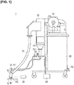
- Figure 1 is a view illustrating a surface treatment device 1 according to the present embodiment.
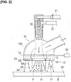
- Figure 2 is a view illustrating a vacuum blast head 10 and an air supply source 20.
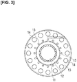
- Figure 3 is a view of the vacuum blast head 10 as viewed from the side of the material B to be treated.
- the surface treatment device comprises a vacuum blast head 10 that sprays a polishing agent P to roughen the surface B1 of the material B to be treated, as illustrated in Figure 1 and Figure 2 .
- the surface treatment device 1 comprises an air supply source 20 that supplies air to an air curtain-forming hole 14 of the vacuum blast head 10 and an auxiliary air injection hole 15.
- the surface treatment device 1 comprises a polishing agent tank 30 in which the polishing agent P is stored, and a compressor 40 for supplying compressed air to the injection nozzle 11.
- the surface treatment device 1 comprises a recovery tank 50 for recovering the polishing agent P that has been sprayed onto the material B to be treated, and a dust collector 60 for collecting dust, etc., that is generated by spraying the polishing agent P on the material B to be treated.
- the surface treatment device 1 comprises an exhauster 70 that forms a negative pressure inside the recovery tank 50 and the dust collector 60.
- the vacuum blast head 10 comprises a main body 10A having a curved shape, an injection nozzle 11 from which the polishing agent P is injected, and a suction hole 12 for suctioning the polishing agent P sprayed onto the material B to be treated, as illustrated in Figure 2 and Figure 3 .
- the vacuum blast head 10 comprises a ring plate 13 that is provided on the lower portion of the main body 10A, and a connecting portion 18 that is provided above the injection nozzle 11.
- the injection nozzle 11 is connected to the polishing agent tank 30 via the connecting portion 18 and a polishing agent hose 31.
- the injection nozzle 11 is connected to the compressor 40 via the connecting portion 18 and an air hose 41.
- the polishing agent hose 31 and the air hose 41 are flexible rubber tubes.
- an injection nozzle 11 configured in this manner, compressed air is supplied to the connecting portion 18 from the compressor 40 via the air hose 41.
- the pressure inside the connecting portion 18 thereby becomes negative, so that the polishing agent P inside the polishing agent tank 30 is drawn into the connecting portion 18 via the polishing agent hose 30.
- the polishing agent P is sprayed from the injection nozzle 11 toward the material B to be treated.
- the surface B1 of the material B to be treated is subjected to blast treatment, and the surface B1 of the material B to be treated is roughened.
- a vacuum hose 51 is connected between the suction hole 12 and the recovery tank 50, as illustrated in Figure 1 and Figure 2 .
- the polishing agent P that is sprayed from the injection nozzle 11 is drawn into the recovery tank 50 by suction air VA via the vacuum hose 51.
- the vacuum hose 51 is a flexible rubber tube.
- the ring plate 13 is connected to the main body 10A.
- the method of connecting the main body 10A and the ring plate 13 is not particularly limited.
- the ring plate 13 comprises an air curtain-forming hole 14 for forming an air curtain AC, and an auxiliary air injection hole 15 for injecting auxiliary air HA, as illustrated in Figure 2 .
- a plurality of the air curtain-forming holes 14 are formed on the radially outer side of the ring plate 13 along the circumferential direction, as illustrated in Figure 3 .
- the air curtain-forming holes 14 configure an air curtain-forming unit 16 together with the air supply source 20.
- the air curtain-forming unit 16 injects air toward the surface B1 of the material B to be treated to form an air curtain AC that surrounds the injected polishing agent P.
- the pressure of the air that forms the air curtain AC is, for example, 1-3 MPa, but no limitation is imposed thereby.
- the air curtain AC formed by the air curtain-forming unit 16 is formed so as to incline outwardly as the air curtain approaches the surface B1 of the material B to be treated, as illustrated in Figure 2 .
- a plurality of the auxiliary air injection holes 15 are formed in the radially inner side of the ring plate 13 along the circumferential direction, as illustrated in Figure 3 .
- the auxiliary air injection holes 15 configure an auxiliary air injection unit 17 together with the air supply unit 20.
- the auxiliary air injection unit 17 injects auxiliary air HA toward the material B to be treated between the air curtain AC and the suction air VA.
- the diameter D2 of the auxiliary air injection hole 15 is configured to be smaller than the diameter D1 of the air curtain-forming hole 14, as illustrated in Figure 2 .
- auxiliary air HA that is at a lower pressure than the air that forms the air curtain AC is injected from the auxiliary air injection hole 15.
- the pressure of the auxiliary air HA is, for example, 0.1 MPa, but no limitation is imposed thereby. In this manner, by setting the pressure of the auxiliary air HA lower than the pressure of the air that forms the air curtain AC, it is possible to form a stable blast space.
- the auxiliary air HA that is injected by the auxiliary air injection unit 17 is injected so as to incline inwardly as the auxiliary air approaches the surface B1 of the material B to be treated, as illustrated in Figure 2 .
- the polishing agent P is stored in the polishing agent tank 30.
- the recovery tank 50 is disposed above the polishing agent tank 30 and is connected thereto via a dump valve 32.
- the dump valve 32 is opened and closed by means of a solenoid valve (not shown).
- the recovery tank 50 recovers the polishing agent P that is sprayed onto the material B to be treated, and the dust, etc., that is generated by spraying the polishing agent P onto the material B to be treated via the suction hole 12 of the vacuum blast head 10.
- the recovery tank 50 is configured from a cyclone separator that separates the polishing agent P from the dust, etc. As described above, the recovery tank 50 is connected to the polishing agent tank 30 via the dump valve 32. Of the polishing agent P and the dust, etc., that are separated in the recovery tank 50, the reusable polishing agent P remains in the recovery tank 50 and is moved to the polishing agent tank 30 when the dump valve 32 is opened.
- the dust collector 60 collects the dust, etc., that has been separated in the recovery tank 50 via a pipe 61.
- a dust box 62 for collecting dust, etc., is provided in the bottom portion of the dust collector 60.
- the dust box 62 is removably provided in order to discard the dust, etc.
- the exhauster 70 is disposed on the upper portion of the dust collector 60.
- the exhauster 70 is rotated by a motor, which is not shown, and forms a negative pressure inside the dust collector 60, the recovery tank 50, and the vacuum hose 51.
- a motor which is not shown
- an air current is generated, from the inside of the blast space to the vacuum hose 51, the recovery tank 50, and the dust collector 60, in that order. Therefore, it is possible to generate suction air VA toward the suction hole 12 in the blast space and to draw up the polishing agent P that is sprayed onto the material B to be treated as well as the dust, etc.
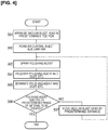
- the vacuum blast head 10 is disposed in a predetermined position above the surface B1 of the material B to be treated (S01).
- an air curtain AC is formed and auxiliary air HA is injected (S02).
- an air curtain AC is formed by supplying air from the air supply source 20 to the air curtain-forming hole 14.
- auxiliary air is injected by supplying air from the air supply source 20 to the auxiliary air injection hole 15.
- the polishing agent P is sprayed (S03). Specifically, compressed air is supplied to the interior of the connecting portion 18 from the compressor 40 via the air hose 41. The interior pressure of the connecting portion 18 and the polishing agent hose 31 becomes negative due to the compressed air. Then, the polishing agent P inside the polishing agent tank 30 is suctioned and sprayed toward the material B to be treated from the injection nozzle 11. As a result, the surface B1 of the material B to be treated is subjected to blast treatment, and the surface B1 of the material B to be treated is roughened. At this time, the dump valve 32 that is disposed above the polishing agent tank 30 is closed and the connection between the recovery tank 50 and the polishing agent tank 30 is cut off.
- the space where the polishing agent is sprayed is surrounded by the air curtain AC, as illustrated in Figure 2 .
- the blast space in which blast treatment is carried out can be made into an enclosed space. Therefore, it is possible to prevent the polishing agent P from being discharged from the blast space to the outside.
- the auxiliary air HA is injected toward the material B to be treated between the air curtain AC and the suction air VA.
- auxiliary air HA can be injected onto the polishing agent P that remains between the air curtain AC and the suction air VA.
- the remaining polishing agent P is released from a static condition and is drawn up by the suction air VA via the suction hole 12. Therefore, it is possible to efficiently recover the polishing agent P.
- polishing agent P that is sprayed onto the surface B1 of the material B to be treated and the dust, etc. are recovered (S04). Specifically, suction air VA is generated by rotating the exhauster 70 and negative pressure is formed inside the dust collector 60, the pipe 61, the recovery tank 50, and the vacuum hose 51. As a result, the polishing agent P that is sprayed onto the material B to be treated and the dust, etc., are recovered into the recovery tank 50 via the vacuum hose 51.
- the polishing agent P and the dust, etc. are separated in the recovery tank 50 (S05).
- the dust, etc., that has been separated in the recovery tank 50 is transported to the dust collector 60 via the pipe 61.
- the dust, etc. then accumulates in the dust box 62, and clean air is exhausted into the atmosphere from the exhauster 70.
- the reusable polishing agent P that is separated in the recovery tank 50 remains in the lower portion of the recovery tank 50.
- Step S06 it is determined whether or not the polishing agent P has been sprayed over a predetermined range of the material B to be treated. If it is determined that the polishing agent P has not been sprayed over the predetermined range of the material B to be treated (S06: NO), the vacuum blast head 10 is moved a predetermined distance (S07). Whether or not the polishing agent P has been sprayed over the predetermined range of the material B to be treated is determined by, for example, a camera, which is not shown, but no particular limitation is imposed thereby. The material B to be treated may be moved a predetermined distance without moving the vacuum blast head 10. Then, after the vacuum blast head 10 has been moved a predetermined distance, the process returns to Step S03.
- the polishing agent P On the other hand, if it is determined that the polishing agent P has been sprayed over the predetermined range of the material B to be treated (S06: YES), the supply of compressed air from the compressed air 40 is stopped. In addition, the negative internal pressure of the polishing agent tank 30 is released by opening the dump valve 32. The injection of the polishing agent P is thereby stopped, and the surface treatment step is ended. At this time, the polishing agent P that remains at the bottom portion of the recovery tank 50 falls into the polishing agent tank 30. In this manner, it is possible to reuse the polishing agent P.
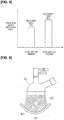
- Figure 5 is a graph illustrating the recovery rate of the polishing agent P in a case in which there is auxiliary air HA and a case in which there is no auxiliary air HA.
- the horizontal axis indicates the cases with and without auxiliary air HA
- the vertical axis indicates the recovery rate of the polishing agent P.
- the recovery rate of the polishing agent P for the case without auxiliary air HA was 75%, as illustrated in Figure 5 .
- the recovery rate of the polishing agent P for the case with auxiliary air HA was 95%. In this manner, the recovery rate of the polishing agent P improved by injection the auxiliary air HA.
- the surface treatment device 1 comprises a vacuum blast head 10, an air curtain-forming unit 16, and an auxiliary air injection unit 17.
- the vacuum blast head 10 comprises an injection nozzle 11 for spraying a polishing agent P used for blast treatment onto the surface B1 of the material B to be treated, and a suction hole 12 for suctioning the injected polishing P agent by suction air VA.
- the air curtain-forming unit 16 injects air toward the surface B1 of the material B to be treated to form an air curtain AC that surrounds the injected polishing agent P.
- the auxiliary air injection unit 17 injects auxiliary air HA, which has a lower pressure than the air that forms the air curtain AC, toward the material B to be treated, between the air curtain AC and the suction air VA.
- the space into which polishing agent P is sprayed is surrounded by the air curtain AC. Therefore, the blast space in which blast treatment is carried out can be made into an enclosed space, and it is possible to prevent the polishing agent P from being discharged from the blast space to the outside.
- the auxiliary air HA is injected toward the material B to be treated between the air curtain AC and the suction air VA. Therefore, auxiliary air HA is injected onto the polishing agent P that remains between the air curtain AC and the suction air VA. At this time, since the pressure of the auxiliary air HA is lower than the pressure that forms the air curtain AC, it is possible to form a stable blast space.
- polishing agent P is released from a static condition and is recovered by the suction air VA via the suction hole 12. Therefore, it is possible to efficiently recover the polishing agent P.
- a treatment chamber to enclose the injection nozzle 11 and the entire material B to be treated need not be provided, it is possible to prevent the device configuration from becoming complicated. Therefore, it is possible to provide a surface treatment device 1 capable of efficiently recovering a polishing agent P without complicating the device configuration.
- the auxiliary air HA that is injected by the auxiliary air injection unit 17 is injected so as to incline inwardly as the auxiliary air approaches the surface B1 of the material B to be treated.
- the polishing agent P that remains within the blast space is moved further inwards in suitable fashion. Therefore, the recovery efficiency of the polishing agent P is further improved.
- the air curtain AC formed by the air curtain-forming unit 16 is formed so as to incline outwardly as the air curtain approaches the surface B1 of the material B to be treated.
- the air curtain AC and the auxiliary air HA are formed so as to incline outwardly as the air curtain approaches the surface B1 of the material B to be treated.
- a polishing agent used for blast treatment is sprayed onto the surface B1 of a material B to be treated, and the injected polishing agent P is drawn up with suction air VA.
- Air is injected toward the surface B1 of the material B to be treated to form an air curtain AC that surrounds the injected polishing agent P.
- auxiliary air HA which has a lower pressure than the air that forms the air curtain AC, is injected toward the material B to be treated, between the air curtain AC and the suction air VA.
- the blast space in which blast treatment is carried out can be made into an enclosed space, and it is possible to prevent the polishing agent P from being discharged from the blast space to the outside.
- the auxiliary air HA is injected toward the material B to be treated between the air curtain AC and the suction air VA. Therefore, auxiliary air HA is injected onto the polishing agent P that remains between the air curtain AC and the suction air VA.
- the pressure of the auxiliary air HA is lower than the pressure that forms the air curtain AC, it is possible to form a stable blast space.
- the remaining polishing agent P is released from a static condition, and is drawn up the suction air VA via the suction hole 12. Therefore, it is possible to efficiently recover the polishing agent P.
- the auxiliary air HA is injected so as to incline inwardly as the auxiliary air approaches the surface B1 of the material B to be treated.
- the polishing agent P that remains in the blast space is moved further inwards in suitable fashion. Therefore, the recovery efficiency of the polishing agent P is further improved.
- the air curtain AC is formed so as to incline outwardly as the air curtain approaches the surface B1 of the material B to be treated.
- the air curtain AC is formed so as to incline outwardly as the air curtain approaches the surface B1 of the material B to be treated.
- the air curtain-forming holes 14 and the auxiliary air injection holes 15 were provided in ring plate 13.
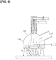
- the air curtain-forming holes 14 and the auxiliary air injection holes 15 may be provided in the main body 110A of the vacuum blast head 110, as illustrated in Figure 9 .
- the suction hole 12 is disposed radially outwardly with respect to the injection nozzle 11.
- the suction hole may be provided radially inward with respect to the injection nozzle.
- the surface treatment device 1 is used for the purpose of roughening the surface B1 of the material B to be treated.
- the surface treatment device 1 may be used for the purpose of cleaning, deburring, shot peening, etc., the surface B1 of the material B to be treated.
- the air curtain-forming holes 14 and the auxiliary air injection holes 15 were provided to the vacuum blast head 10.
- the air curtain-forming holes and the auxiliary air injection holes may be provided separately from the vacuum blast head.
Landscapes
- Engineering & Computer Science (AREA)
- Mechanical Engineering (AREA)
- Application Of Or Painting With Fluid Materials (AREA)
- Details Or Accessories Of Spraying Plant Or Apparatus (AREA)
- Cleaning And De-Greasing Of Metallic Materials By Chemical Methods (AREA)
Abstract
Description
- The present invention relates to a surface treatment device and a surface treatment method.
- In recent years, for reasons of weight reduction, carbon fiber-reinforced plastic (CFRP) is being used in vehicle body structures. When manufacturing a vehicle body structure from CFRP, members are bonded with an adhesive. In this case, as a pretreatment for adhesion, the surface of the material to be treated as a member is subjected to blast treatment by means of a vacuum blast treatment.
- In a vacuum blast treatment, a polishing agent is injected onto the material to be treated to roughen the surface of the material to be treated, to thereby increase the adhesion area and improve the bonding strength. In addition, the polishing agent sprayed onto the material to be treated, as well as dust, etc., generated by spraying the polishing agent on the material to be treated, is drawn up; the polishing agent is separated from the dust, etc.; and the polishing agent is recovered so that the polishing agent can be reused.
- As described above, since blast treatment is carried out by reusing the polishing agent in a vacuum blast treatment, it is required that the polishing agent be efficiently recovered.
- In this regard, for example, the following
Patent Document 1 discloses a method in which the blast treatment of a material to be treated is carried out by enclosing the injection nozzle and the entire material to be treated within a treatment chamber. - Patent Document 1: Japanese Laid-Open Patent Application No.
2001-334466 - However, since a treatment chamber for enclosing the material to be treated is required in the method disclosed in
Patent Document 1, there is the problem that the device configuration becomes complicated. - In order to solve the problem described above, an object of the present invention is to provide a surface treatment device and a surface treatment method capable of efficiently recovering the polishing agent without complicating the device configuration.
- The surface treatment device according to the present invention which realizes the object described above comprises a vacuum blast head, an air curtain-forming unit, and an auxiliary air injection unit. The vacuum blast head comprises an injection nozzle for spraying a polishing agent used for blast treatment onto the surface of a material to be treated, and a suction hole for suctioning the injected polishing agent with suction air. The air curtain-forming unit injects air toward the surface of the material to be treated to form an air curtain that surrounds the injected polishing agent. The auxiliary air injection unit injects auxiliary air between the air curtain and the suction air towards the material to be treated at a lower pressure than the air forming the air curtain.
- In addition, in the surface treatment method according to the present invention which realizes the object described above, a polishing agent used for blast treatment is sprayed onto the surface of a material to be treated and the injected polishing agent is drawn up with suction air. Air is injected toward the surface of the material to be treated to form an air curtain that surrounds the injected polishing agent. Auxiliary air is injected between the air curtain and the suction air towards the material to be treated at a lower pressure than the air forming the air curtain.
- According to the surface treatment device and the surface treatment method described above, the space into which polishing agent is sprayed is surrounded by an air curtain. Thus, the blast space in which a blast treatment is carried out can be formed within a closed space. Therefore, it is possible to prevent the polishing agent from being discharged from the blast space to the outside. Additionally, the auxiliary air is injected toward the material to be treated between the air curtain and the suction air. Thus, auxiliary air is injected onto the polishing agent that remains between the air curtain and the suction air. At this time, since the pressure of the auxiliary air is lower than the pressure for forming the air curtain, it is possible to form a stable blast space. As a result, the remaining polishing agent is released from a static condition and recovered by the suction air via the suction hole. Therefore, it is possible to efficiently recover the polishing agent. In addition, since a treatment chamber to enclose the injection nozzle and all of the material to be treated need not be provided, it is possible to avoid a complex device configuration. Therefore, it is possible to provide a surface treatment device and a surface treatment method capable of efficiently recovering the polishing agent without resorting to a complex device configuration.
-
- [
Figure 1 ] is a view illustrating a surface treatment device according to the present embodiment. - [
Figure 2 ] is a view illustrating a vacuum blast head and an air supply source of the surface treatment device. - [
Figure 3 ] is a view of the vacuum blast head as viewed from the side of the material to be treated. - [
Figure 4 ] is a flowchart illustrating a surface treatment method according to the present embodiment. - [
Figure 5 ] is a graph illustrating the recovery rate of the polishing agent in the case in which there is auxiliary air and the case in which there is no auxiliary air. - [
Figure 6 ] is a view of the case in which the surface treatment device according to the present embodiment is applied to the material to be treated which has a curved shape. - [
Figure 7 ] is a view of the case in which the surface treatment device according to the present embodiment is applied to the material to be treated which has a curved shape. - [
Figure 8 ] is a view of the case in which the surface treatment device according to the present embodiment is applied to the material to be treated which has a bent shape. - [
Figure 9 ] is a view illustrating a vacuum blast head of a surface treatment device according to a modified example. - Embodiments of the present invention will be explained below with reference to the appended drawings. In the explanations of the drawings, identical elements are given the same reference symbols and redundant explanations are omitted. The dimensional ratios used in the drawings may be exaggerated for the sake of convenience of the explanation and may differ from the actual ratios.
- The
surface treatment device 1 according to the present embodiment is a vacuum blast device. In general, thesurface treatment device 1 sprays a polishing agent onto a material B to be treated and subjects the surface B1 of the material B to be treated to blast treatment to thereby roughen the surface B1 of the material B to be treated. By roughening the surface B1 of the material B to be treated, the adhesion area increases and the bonding strength by means of the adhesive is improved. In addition, thesurface treatment device 1 recovers the polishing agent sprayed onto the material B to be treated, as well as dust, etc., generated by spraying the polishing agent on the material B to be treated, and separates the polishing agent from the dust, etc. Thus, only the polishing agent that can be reused is recovered for reuse. - Examples of a material B to be treated include automobile parts made of CFRP, but no limitation is imposed thereby.
- Examples of the polishing agent include alumina (Al2O3), carborundum, river sand, quartz sand, and emery, but from the standpoint of being economical and having a high blast treatment, alumina is preferable.
-
Figure 1 is a view illustrating asurface treatment device 1 according to the present embodiment.Figure 2 is a view illustrating avacuum blast head 10 and anair supply source 20.Figure 3 is a view of thevacuum blast head 10 as viewed from the side of the material B to be treated. - The surface treatment device comprises a
vacuum blast head 10 that sprays a polishing agent P to roughen the surface B1 of the material B to be treated, as illustrated inFigure 1 andFigure 2 . Thesurface treatment device 1 comprises anair supply source 20 that supplies air to an air curtain-forminghole 14 of thevacuum blast head 10 and an auxiliaryair injection hole 15. In addition, thesurface treatment device 1 comprises apolishing agent tank 30 in which the polishing agent P is stored, and acompressor 40 for supplying compressed air to theinjection nozzle 11. Additionally, thesurface treatment device 1 comprises arecovery tank 50 for recovering the polishing agent P that has been sprayed onto the material B to be treated, and adust collector 60 for collecting dust, etc., that is generated by spraying the polishing agent P on the material B to be treated. In addition, thesurface treatment device 1 comprises anexhauster 70 that forms a negative pressure inside therecovery tank 50 and thedust collector 60. - The
vacuum blast head 10 comprises amain body 10A having a curved shape, aninjection nozzle 11 from which the polishing agent P is injected, and asuction hole 12 for suctioning the polishing agent P sprayed onto the material B to be treated, as illustrated inFigure 2 andFigure 3 . In addition, thevacuum blast head 10 comprises aring plate 13 that is provided on the lower portion of themain body 10A, and a connectingportion 18 that is provided above theinjection nozzle 11. - The
injection nozzle 11 is connected to the polishingagent tank 30 via the connectingportion 18 and a polishingagent hose 31. In addition, theinjection nozzle 11 is connected to thecompressor 40 via the connectingportion 18 and anair hose 41. The polishingagent hose 31 and theair hose 41 are flexible rubber tubes. - In an
injection nozzle 11 configured in this manner, compressed air is supplied to the connectingportion 18 from thecompressor 40 via theair hose 41. The pressure inside the connectingportion 18 thereby becomes negative, so that the polishing agent P inside the polishingagent tank 30 is drawn into the connectingportion 18 via the polishingagent hose 30. Then, the polishing agent P is sprayed from theinjection nozzle 11 toward the material B to be treated. As a result, the surface B1 of the material B to be treated is subjected to blast treatment, and the surface B1 of the material B to be treated is roughened. - A
vacuum hose 51 is connected between thesuction hole 12 and therecovery tank 50, as illustrated inFigure 1 andFigure 2 . The polishing agent P that is sprayed from theinjection nozzle 11 is drawn into therecovery tank 50 by suction air VA via thevacuum hose 51. Thevacuum hose 51 is a flexible rubber tube. - The
ring plate 13 is connected to themain body 10A. The method of connecting themain body 10A and thering plate 13 is not particularly limited. Thering plate 13 comprises an air curtain-forminghole 14 for forming an air curtain AC, and an auxiliaryair injection hole 15 for injecting auxiliary air HA, as illustrated inFigure 2 . - A plurality of the air curtain-forming
holes 14 are formed on the radially outer side of thering plate 13 along the circumferential direction, as illustrated inFigure 3 . The air curtain-formingholes 14 configure an air curtain-formingunit 16 together with theair supply source 20. - By being supplied air from the
air supply source 20, the air curtain-formingunit 16 injects air toward the surface B1 of the material B to be treated to form an air curtain AC that surrounds the injected polishing agent P. The pressure of the air that forms the air curtain AC is, for example, 1-3 MPa, but no limitation is imposed thereby. - The air curtain AC formed by the air curtain-forming
unit 16 is formed so as to incline outwardly as the air curtain approaches the surface B1 of the material B to be treated, as illustrated inFigure 2 . Thus, it is possible to prevent interference between the air curtain AC and the auxiliary air HA and to form a stable blast space. - A plurality of the auxiliary air injection holes 15 are formed in the radially inner side of the
ring plate 13 along the circumferential direction, as illustrated inFigure 3 . The auxiliary air injection holes 15 configure an auxiliaryair injection unit 17 together with theair supply unit 20. - By air being supplied from the
air supply source 20, the auxiliaryair injection unit 17 injects auxiliary air HA toward the material B to be treated between the air curtain AC and the suction air VA. The diameter D2 of the auxiliaryair injection hole 15 is configured to be smaller than the diameter D1 of the air curtain-forminghole 14, as illustrated inFigure 2 . Thus, auxiliary air HA that is at a lower pressure than the air that forms the air curtain AC is injected from the auxiliaryair injection hole 15. The pressure of the auxiliary air HA is, for example, 0.1 MPa, but no limitation is imposed thereby. In this manner, by setting the pressure of the auxiliary air HA lower than the pressure of the air that forms the air curtain AC, it is possible to form a stable blast space. - The auxiliary air HA that is injected by the auxiliary
air injection unit 17 is injected so as to incline inwardly as the auxiliary air approaches the surface B1 of the material B to be treated, as illustrated inFigure 2 . Thus, it is possible to move the polishing agent P that remains between the air curtain AC and the suction air VA inward from the blast space on which the suction air VA acts. Therefore, it is possible to suitably suction the polishing agent P that has been moved inwards. Therefore, the recovery efficiency of the polishing agent P is improved. - The polishing agent P is stored in the polishing
agent tank 30. Therecovery tank 50 is disposed above the polishingagent tank 30 and is connected thereto via adump valve 32. Thedump valve 32 is opened and closed by means of a solenoid valve (not shown). - The
recovery tank 50 recovers the polishing agent P that is sprayed onto the material B to be treated, and the dust, etc., that is generated by spraying the polishing agent P onto the material B to be treated via thesuction hole 12 of thevacuum blast head 10. Therecovery tank 50 is configured from a cyclone separator that separates the polishing agent P from the dust, etc. As described above, therecovery tank 50 is connected to the polishingagent tank 30 via thedump valve 32. Of the polishing agent P and the dust, etc., that are separated in therecovery tank 50, the reusable polishing agent P remains in therecovery tank 50 and is moved to the polishingagent tank 30 when thedump valve 32 is opened. - The
dust collector 60 collects the dust, etc., that has been separated in therecovery tank 50 via apipe 61. Adust box 62 for collecting dust, etc., is provided in the bottom portion of thedust collector 60. Thedust box 62 is removably provided in order to discard the dust, etc. - The
exhauster 70 is disposed on the upper portion of thedust collector 60. Theexhauster 70 is rotated by a motor, which is not shown, and forms a negative pressure inside thedust collector 60, therecovery tank 50, and thevacuum hose 51. Thus, an air current is generated, from the inside of the blast space to thevacuum hose 51, therecovery tank 50, and thedust collector 60, in that order. Therefore, it is possible to generate suction air VA toward thesuction hole 12 in the blast space and to draw up the polishing agent P that is sprayed onto the material B to be treated as well as the dust, etc. - Next, the surface treatment method using the
surface treatment device 1 according to the present embodiment will be described with reference to the flowchart ofFigure 4 . - First, the
vacuum blast head 10 is disposed in a predetermined position above the surface B1 of the material B to be treated (S01). - Next, an air curtain AC is formed and auxiliary air HA is injected (S02). Specifically, an air curtain AC is formed by supplying air from the
air supply source 20 to the air curtain-forminghole 14. In addition, auxiliary air is injected by supplying air from theair supply source 20 to the auxiliaryair injection hole 15. - Next, the polishing agent P is sprayed (S03). Specifically, compressed air is supplied to the interior of the connecting
portion 18 from thecompressor 40 via theair hose 41. The interior pressure of the connectingportion 18 and the polishingagent hose 31 becomes negative due to the compressed air. Then, the polishing agent P inside the polishingagent tank 30 is suctioned and sprayed toward the material B to be treated from theinjection nozzle 11. As a result, the surface B1 of the material B to be treated is subjected to blast treatment, and the surface B1 of the material B to be treated is roughened. At this time, thedump valve 32 that is disposed above the polishingagent tank 30 is closed and the connection between therecovery tank 50 and the polishingagent tank 30 is cut off. - In this manner, by forming an air curtain AC and spraying the polishing agent P while injecting auxiliary air HA, the space where the polishing agent is sprayed is surrounded by the air curtain AC, as illustrated in
Figure 2 . Thus, the blast space in which blast treatment is carried out can be made into an enclosed space. Therefore, it is possible to prevent the polishing agent P from being discharged from the blast space to the outside. Additionally, the auxiliary air HA is injected toward the material B to be treated between the air curtain AC and the suction air VA. Thus, auxiliary air HA can be injected onto the polishing agent P that remains between the air curtain AC and the suction air VA. As a result, the remaining polishing agent P is released from a static condition and is drawn up by the suction air VA via thesuction hole 12. Therefore, it is possible to efficiently recover the polishing agent P. - Next, the polishing agent P that is sprayed onto the surface B1 of the material B to be treated and the dust, etc., are recovered (S04). Specifically, suction air VA is generated by rotating the
exhauster 70 and negative pressure is formed inside thedust collector 60, thepipe 61, therecovery tank 50, and thevacuum hose 51. As a result, the polishing agent P that is sprayed onto the material B to be treated and the dust, etc., are recovered into therecovery tank 50 via thevacuum hose 51. - Next, the polishing agent P and the dust, etc., are separated in the recovery tank 50 (S05). The dust, etc., that has been separated in the
recovery tank 50 is transported to thedust collector 60 via thepipe 61. The dust, etc., then accumulates in thedust box 62, and clean air is exhausted into the atmosphere from theexhauster 70. On the other hand, the reusable polishing agent P that is separated in therecovery tank 50 remains in the lower portion of therecovery tank 50. - Next, it is determined whether or not the polishing agent P has been sprayed over a predetermined range of the material B to be treated (S06). If it is determined that the polishing agent P has not been sprayed over the predetermined range of the material B to be treated (S06: NO), the
vacuum blast head 10 is moved a predetermined distance (S07). Whether or not the polishing agent P has been sprayed over the predetermined range of the material B to be treated is determined by, for example, a camera, which is not shown, but no particular limitation is imposed thereby. The material B to be treated may be moved a predetermined distance without moving thevacuum blast head 10. Then, after thevacuum blast head 10 has been moved a predetermined distance, the process returns to Step S03. - On the other hand, if it is determined that the polishing agent P has been sprayed over the predetermined range of the material B to be treated (S06: YES), the supply of compressed air from the
compressed air 40 is stopped. In addition, the negative internal pressure of the polishingagent tank 30 is released by opening thedump valve 32. The injection of the polishing agent P is thereby stopped, and the surface treatment step is ended. At this time, the polishing agent P that remains at the bottom portion of therecovery tank 50 falls into the polishingagent tank 30. In this manner, it is possible to reuse the polishing agent P. - Next, the effects of the
surface treatment device 1 and the surface treatment method according to the present embodiment will be described with reference toFigure 5 . -
Figure 5 is a graph illustrating the recovery rate of the polishing agent P in a case in which there is auxiliary air HA and a case in which there is no auxiliary air HA. InFigure 5 , the horizontal axis indicates the cases with and without auxiliary air HA, and the vertical axis indicates the recovery rate of the polishing agent P. - The recovery rate of the polishing agent P for the case without auxiliary air HA was 75%, as illustrated in
Figure 5 . In contrast, the recovery rate of the polishing agent P for the case with auxiliary air HA was 95%. In this manner, the recovery rate of the polishing agent P improved by injection the auxiliary air HA. - As described above, the
surface treatment device 1 according to the present embodiment comprises avacuum blast head 10, an air curtain-formingunit 16, and an auxiliaryair injection unit 17. Thevacuum blast head 10 comprises aninjection nozzle 11 for spraying a polishing agent P used for blast treatment onto the surface B1 of the material B to be treated, and asuction hole 12 for suctioning the injected polishing P agent by suction air VA. The air curtain-formingunit 16 injects air toward the surface B1 of the material B to be treated to form an air curtain AC that surrounds the injected polishing agent P. In addition, the auxiliaryair injection unit 17 injects auxiliary air HA, which has a lower pressure than the air that forms the air curtain AC, toward the material B to be treated, between the air curtain AC and the suction air VA. Thus, the space into which polishing agent P is sprayed is surrounded by the air curtain AC. Therefore, the blast space in which blast treatment is carried out can be made into an enclosed space, and it is possible to prevent the polishing agent P from being discharged from the blast space to the outside. Additionally, the auxiliary air HA is injected toward the material B to be treated between the air curtain AC and the suction air VA. Therefore, auxiliary air HA is injected onto the polishing agent P that remains between the air curtain AC and the suction air VA. At this time, since the pressure of the auxiliary air HA is lower than the pressure that forms the air curtain AC, it is possible to form a stable blast space. As a result, the remaining polishing agent P is released from a static condition and is recovered by the suction air VA via thesuction hole 12. Therefore, it is possible to efficiently recover the polishing agent P. In addition, since a treatment chamber to enclose theinjection nozzle 11 and the entire material B to be treated need not be provided, it is possible to prevent the device configuration from becoming complicated. Therefore, it is possible to provide asurface treatment device 1 capable of efficiently recovering a polishing agent P without complicating the device configuration. - In addition, according to the
surface treatment device 1 of the present embodiment described above, with respect to curved or bent materials B1, B2, B3 to be treated, it is possible to cover blast surfaces S1, S2, S3 with the air curtain AC and thevacuum blast head 10, as illustrated inFigures 6-8 . Therefore, it is possible to suitably carry out blast treatment on curved or bent materials B1, B2, B3 to be treated - Additionally, the auxiliary air HA that is injected by the auxiliary
air injection unit 17 is injected so as to incline inwardly as the auxiliary air approaches the surface B1 of the material B to be treated. Thus, the polishing agent P that remains within the blast space is moved further inwards in suitable fashion. Therefore, the recovery efficiency of the polishing agent P is further improved. - In addition, the air curtain AC formed by the air curtain-forming
unit 16 is formed so as to incline outwardly as the air curtain approaches the surface B1 of the material B to be treated. Thus, it is possible to prevent interference between the air curtain AC and the auxiliary air HA, and to form a stable blast space. - Additionally, as described above, in the surface treatment method according to the present embodiment, a polishing agent used for blast treatment is sprayed onto the surface B1 of a material B to be treated, and the injected polishing agent P is drawn up with suction air VA. Air is injected toward the surface B1 of the material B to be treated to form an air curtain AC that surrounds the injected polishing agent P. Then, auxiliary air HA, which has a lower pressure than the air that forms the air curtain AC, is injected toward the material B to be treated, between the air curtain AC and the suction air VA. Thus, the space into which polishing agent P is sprayed is surrounded by the air curtain AC. Therefore, the blast space in which blast treatment is carried out can be made into an enclosed space, and it is possible to prevent the polishing agent P from being discharged from the blast space to the outside. Additionally, the auxiliary air HA is injected toward the material B to be treated between the air curtain AC and the suction air VA. Therefore, auxiliary air HA is injected onto the polishing agent P that remains between the air curtain AC and the suction air VA. At this time, since the pressure of the auxiliary air HA is lower than the pressure that forms the air curtain AC, it is possible to form a stable blast space. As a result, the remaining polishing agent P is released from a static condition, and is drawn up the suction air VA via the
suction hole 12. Therefore, it is possible to efficiently recover the polishing agent P. In addition, since a treatment chamber to enclose theinjection nozzle 11 and the entire material B to be treated need not be provided, it is possible to prevent the device configuration from becoming complicated. Therefore, it is possible to provide a surface treatment method with which it is possible efficiently recover a polishing agent P without complicating the device configuration. - Additionally, the auxiliary air HA is injected so as to incline inwardly as the auxiliary air approaches the surface B1 of the material B to be treated. Thus, the polishing agent P that remains in the blast space is moved further inwards in suitable fashion. Therefore, the recovery efficiency of the polishing agent P is further improved.
- In addition, the air curtain AC is formed so as to incline outwardly as the air curtain approaches the surface B1 of the material B to be treated. Thus, it is possible to prevent interference between the air curtain AC and the auxiliary air HA and to form a stable blast space.
- The present invention is not limited to the embodiment described above; various modifications are possible within the scope of the claims.
- For example, in the embodiment described above, the air curtain-forming
holes 14 and the auxiliary air injection holes 15 were provided inring plate 13. However, the air curtain-formingholes 14 and the auxiliary air injection holes 15 may be provided in themain body 110A of thevacuum blast head 110, as illustrated inFigure 9 . - In addition, in the embodiment described above, the
suction hole 12 is disposed radially outwardly with respect to theinjection nozzle 11. However, the suction hole may be provided radially inward with respect to the injection nozzle. - Additionally, in the embodiment described above, the
surface treatment device 1 is used for the purpose of roughening the surface B1 of the material B to be treated. However, thesurface treatment device 1 may be used for the purpose of cleaning, deburring, shot peening, etc., the surface B1 of the material B to be treated. - In addition, in the embodiment described above, the air curtain-forming
holes 14 and the auxiliary air injection holes 15 were provided to thevacuum blast head 10. However, the air curtain-forming holes and the auxiliary air injection holes may be provided separately from the vacuum blast head. -
- 1 Surface treatment device,
- 10 Vacuum blast head,
- 11 Injection nozzle,
- 12 Suction hole,
- 14 Air curtain-forming hole,
- 15 Auxiliary air injection hole,
- 16 Air curtain-forming unit,
- 17 Auxiliary air injection unit,
- 20 Air supply source,
- AC Air curtain,
- B Material to be treated
- B1 Surface of the material to be treated
- HA Auxiliary air,
- P Polishing agent,
- VA Suction air.
Claims (6)
- A surface treatment device, characterized in that the surface treatment device comprises:a vacuum blast head including an injection nozzle for spraying a polishing agent for blast treatment on a surface of a material to be treated, and a suction hole for suctioning the injected polishing agent with suction air;an air curtain-forming unit that injects air toward the surface of the material to be treated to form an air curtain that surrounds the injected polishing agent; andan auxiliary air injection unit that injects auxiliary air between the air curtain and the suction air towards the material to be treated at a lower pressure than the air forming the air curtain.
- The surface treatment device as recited in claim 1, wherein the auxiliary air injected by the auxiliary air injection unit is inclined inwardly as the auxiliary air approaches the surface of the material to be treated.
- The surface treatment device as recited in claim 1 or 2, wherein the air curtain that is formed by the air curtain-forming unit is inclined outwardly as the air curtain approaches the surface of the material to be treated.
- A surface treatment method for spraying a polishing agent for blast treatment on a surface of a material to be treated, and suctioning the injected polishing agent with suction air, the method comprising:injecting air towards the surface of the material to be treated to form an air curtain that surrounds the injected polishing agent; andinjecting auxiliary air between the air curtain and the suction air toward the material to be treated at a lower pressure than the air that forms the air curtain.
- The surface treatment method recited in claim 4, wherein the auxiliary air is injected so as to incline inwardly as the auxiliary air approaches the surface of the material to be treated.
- The surface treatment method recited in claim 4 or 5, wherein the air curtain is formed so as to incline outwardly as the air curtain approaches the surface of the material to be treated.
Applications Claiming Priority (1)
| Application Number | Priority Date | Filing Date | Title |
|---|---|---|---|
| PCT/JP2015/081500 WO2017081730A1 (en) | 2015-11-09 | 2015-11-09 | Surface treatment device and surface treatment method |
Publications (3)
| Publication Number | Publication Date |
|---|---|
| EP3375568A1 true EP3375568A1 (en) | 2018-09-19 |
| EP3375568A4 EP3375568A4 (en) | 2018-11-14 |
| EP3375568B1 EP3375568B1 (en) | 2019-10-09 |
Family
ID=58694853
Family Applications (1)
| Application Number | Title | Priority Date | Filing Date |
|---|---|---|---|
| EP15908254.4A Active EP3375568B1 (en) | 2015-11-09 | 2015-11-09 | Surface treatment device and surface treatment method |
Country Status (9)
| Country | Link |
|---|---|
| US (1) | US10668596B2 (en) |
| EP (1) | EP3375568B1 (en) |
| JP (1) | JP6540821B2 (en) |
| KR (1) | KR20180063191A (en) |
| CN (1) | CN108290274B (en) |
| BR (1) | BR112018009392A8 (en) |
| MX (1) | MX2018005718A (en) |
| RU (1) | RU2690060C1 (en) |
| WO (1) | WO2017081730A1 (en) |
Cited By (2)
| Publication number | Priority date | Publication date | Assignee | Title |
|---|---|---|---|---|
| EP3482877A1 (en) * | 2017-11-10 | 2019-05-15 | Premium AEROTEC GmbH | Method for treating the surface of a fibre composite component |
| EP3698920A1 (en) | 2019-02-25 | 2020-08-26 | Airbus Operations | Tool for stripping by spraying and suction |
Families Citing this family (8)
| Publication number | Priority date | Publication date | Assignee | Title |
|---|---|---|---|---|
| WO2019094541A1 (en) * | 2017-11-08 | 2019-05-16 | Jm Technologies Llc | Apparatus and system for transferring materials and corresponding method of use thereof |
| JP6619037B2 (en) * | 2018-02-07 | 2019-12-11 | 有限会社平岡製工社 | Blasting equipment |
| CN110919551A (en) * | 2019-11-04 | 2020-03-27 | 江苏顿科智能装备有限公司 | An integrated non-contact curved nozzle spray gun for sand blasting, sand returning and dust removal |
| CN110919553A (en) * | 2019-11-04 | 2020-03-27 | 江苏顿科智能装备有限公司 | A non-contact double-barreled spray gun integrating sand blasting, sand returning and dust removal |
| CN110919550A (en) * | 2019-11-04 | 2020-03-27 | 江苏顿科智能装备有限公司 | Large-scale pipeline inner wall spray gun group for online sand suction and dust removal |
| CN110919552A (en) * | 2019-11-04 | 2020-03-27 | 江苏顿科智能装备有限公司 | An integrated non-contact array spray gun for sand blasting, sand returning and dust removal |
| WO2022185734A1 (en) * | 2021-03-02 | 2022-09-09 | 住友重機械マリンエンジニアリング株式会社 | Blasting machine, and ship |
| JP7806435B2 (en) * | 2021-10-22 | 2026-01-27 | 新東工業株式会社 | Dust removal equipment |
Family Cites Families (22)
| Publication number | Priority date | Publication date | Assignee | Title |
|---|---|---|---|---|
| US2478557A (en) * | 1947-09-13 | 1949-08-09 | Walter H Bell | Sprayer and sprayer head for fluent coating materials |
| US2644275A (en) * | 1949-04-11 | 1953-07-07 | E C T A Soc | Water curtain projecting device for use with sand blasting apparatus |
| SU403544A1 (en) * | 1970-04-24 | 1973-10-26 | CRUSHED HEAD | |
| SU1063585A1 (en) * | 1981-12-17 | 1983-12-30 | Ворошиловградский машиностроительный институт | Apparatus for abrasive working of machine parts |
| JPS59193657U (en) * | 1983-06-09 | 1984-12-22 | 厚地鉄工株式会社 | sandblasting equipment |
| US4654925A (en) * | 1986-04-28 | 1987-04-07 | Grave Dale L | Nozzle structure for a surface covering cleaning machine |
| JPH02198680A (en) * | 1988-10-25 | 1990-08-07 | Nippon Kansen Kogyo Kk | Preventing mechanism for scattering due to air |
| US4976005A (en) * | 1989-06-12 | 1990-12-11 | Dale L Grave | Cleaning tool with demand-responsive air port |
| US5309683A (en) * | 1992-01-28 | 1994-05-10 | Sandroid Systems, Inc. | Recovery system |
| JPH06190308A (en) | 1992-12-25 | 1994-07-12 | Shiyuto Kosoku Doro Gijutsu Center | Spray painting equipment |
| EP0631849B1 (en) * | 1993-07-01 | 1998-09-02 | Brändle Metallbau AG | Method and device for cleaning surfaces |
| JPH106221A (en) * | 1996-06-18 | 1998-01-13 | Tada Kikai:Kk | Sand blasting device |
| DE19651107C2 (en) * | 1996-12-09 | 1999-12-16 | Anton Jaeger | Sandblasting nozzle |
| US5833521A (en) * | 1996-12-27 | 1998-11-10 | Ltc Americas, Inc. | Air cushioned vacuum blast head |
| JP3099000B2 (en) * | 1999-06-15 | 2000-10-16 | ニチハ株式会社 | How to paint building boards |
| JP2001334466A (en) | 2000-05-25 | 2001-12-04 | Sony Corp | Blast processing method and blast processing apparatus |
| KR100436540B1 (en) * | 2001-11-23 | 2004-06-19 | 한국수력원자력 주식회사 | Removal Methods and Equipments for Particulate Contaminants Resulting from CO2 Blasting Decontamination |
| US8801499B2 (en) * | 2009-04-21 | 2014-08-12 | Sharp Kabushiki Kaisha | Blasting apparatus and method for blast processing |
| US8561486B2 (en) | 2009-07-13 | 2013-10-22 | Enertechnix, Inc | Particle interrogation devices and methods |
| ATE545136T1 (en) * | 2009-10-05 | 2012-02-15 | Linde Ag | METHOD FOR COLLECTING MATERIAL DURING DRY ICE BLASTING |
| JP5746901B2 (en) * | 2011-04-14 | 2015-07-08 | 株式会社不二製作所 | Polishing method and nozzle structure of blast processing apparatus |
| US20150240419A1 (en) * | 2012-08-24 | 2015-08-27 | Hiroshi Sekiya | Nozzle device |
-
2015
- 2015-11-09 US US15/768,593 patent/US10668596B2/en active Active
- 2015-11-09 RU RU2018121213A patent/RU2690060C1/en active
- 2015-11-09 EP EP15908254.4A patent/EP3375568B1/en active Active
- 2015-11-09 WO PCT/JP2015/081500 patent/WO2017081730A1/en not_active Ceased
- 2015-11-09 MX MX2018005718A patent/MX2018005718A/en unknown
- 2015-11-09 CN CN201580084450.6A patent/CN108290274B/en active Active
- 2015-11-09 KR KR1020187012049A patent/KR20180063191A/en not_active Ceased
- 2015-11-09 BR BR112018009392A patent/BR112018009392A8/en not_active Application Discontinuation
- 2015-11-09 JP JP2017549884A patent/JP6540821B2/en active Active
Cited By (6)
| Publication number | Priority date | Publication date | Assignee | Title |
|---|---|---|---|---|
| EP3482877A1 (en) * | 2017-11-10 | 2019-05-15 | Premium AEROTEC GmbH | Method for treating the surface of a fibre composite component |
| US11541508B2 (en) | 2017-11-10 | 2023-01-03 | Premium Aerotec Gmbh | Method for treating a surface of a fibre composite component |
| EP3698920A1 (en) | 2019-02-25 | 2020-08-26 | Airbus Operations | Tool for stripping by spraying and suction |
| FR3093019A1 (en) * | 2019-02-25 | 2020-08-28 | Airbus Operations | spray and suction stripping tool |
| CN111604816A (en) * | 2019-02-25 | 2020-09-01 | 空中客车运营简化股份公司 | Tool for descaling by spraying and suction |
| US11465258B2 (en) | 2019-02-25 | 2022-10-11 | Airbus Operations Sas | Tool for pickling by means of spraying and suction |
Also Published As
| Publication number | Publication date |
|---|---|
| EP3375568A4 (en) | 2018-11-14 |
| BR112018009392A2 (en) | 2018-11-13 |
| CN108290274A (en) | 2018-07-17 |
| KR20180063191A (en) | 2018-06-11 |
| MX2018005718A (en) | 2018-08-01 |
| JPWO2017081730A1 (en) | 2018-09-06 |
| RU2690060C1 (en) | 2019-05-30 |
| WO2017081730A1 (en) | 2017-05-18 |
| EP3375568B1 (en) | 2019-10-09 |
| CN108290274B (en) | 2019-08-02 |
| US20180297172A1 (en) | 2018-10-18 |
| BR112018009392A8 (en) | 2019-02-26 |
| JP6540821B2 (en) | 2019-07-10 |
| US10668596B2 (en) | 2020-06-02 |
Similar Documents
| Publication | Publication Date | Title |
|---|---|---|
| EP3375568B1 (en) | Surface treatment device and surface treatment method | |
| US11000936B2 (en) | Method for recovering machining waste by input of energy and machining machine comprising a waste recovery system | |
| CN107249821B (en) | Nozzle assembly and surface treatment method using same | |
| JP2017092397A (en) | Wafer transfer apparatus | |
| JP2017189841A (en) | Surface treatment apparatus and surface treatment method | |
| WO2012056597A1 (en) | Blasting device | |
| KR101622759B1 (en) | Blasting inject collecting system using eco-friendly wide width blasting inject collecting chamber with generating swirl | |
| WO2021029235A1 (en) | Negative-pressure suction seal for negative-pressure suction movement device | |
| CN211992508U (en) | Sand blasting equipment for blasting sand on small parts | |
| JP6753124B2 (en) | Surface treatment equipment and surface treatment method | |
| CN105382707A (en) | Blast treatment device and blast treatment method | |
| US11541508B2 (en) | Method for treating a surface of a fibre composite component | |
| KR20090104303A (en) | Sandblast device | |
| CN216856081U (en) | Dust removal cabin gas explosion cleaning mechanism of sand blasting recovery equipment | |
| CN216098381U (en) | Steel sand splashing prevention device in steel pipe rust removal sanding machine | |
| JP7595504B2 (en) | Film forming apparatus and film forming method | |
| CN218052104U (en) | Sand blasting equipment | |
| CN215357983U (en) | Online synchronous suction and delivery sand blasting machine | |
| CN208695393U (en) | The powder spraying chamber of high efficiente callback powder | |
| KR20100110095A (en) | A dry air-blast apparatus | |
| CN207930513U (en) | A kind of sand-blasting machine with flash remove function | |
| KR101626336B1 (en) | Blasting Apparatus | |
| KR200260565Y1 (en) | Air Lancing System | |
| KR100627159B1 (en) | Blaster | |
| KR20250015152A (en) | A clamp type adaptor for pipe blasting |
Legal Events
| Date | Code | Title | Description |
|---|---|---|---|
| STAA | Information on the status of an ep patent application or granted ep patent |
Free format text: STATUS: THE INTERNATIONAL PUBLICATION HAS BEEN MADE |
|
| PUAI | Public reference made under article 153(3) epc to a published international application that has entered the european phase |
Free format text: ORIGINAL CODE: 0009012 |
|
| STAA | Information on the status of an ep patent application or granted ep patent |
Free format text: STATUS: REQUEST FOR EXAMINATION WAS MADE |
|
| 17P | Request for examination filed |
Effective date: 20180605 |
|
| AK | Designated contracting states |
Kind code of ref document: A1 Designated state(s): AL AT BE BG CH CY CZ DE DK EE ES FI FR GB GR HR HU IE IS IT LI LT LU LV MC MK MT NL NO PL PT RO RS SE SI SK SM TR |
|
| AX | Request for extension of the european patent |
Extension state: BA ME |
|
| A4 | Supplementary search report drawn up and despatched |
Effective date: 20181016 |
|
| RIC1 | Information provided on ipc code assigned before grant |
Ipc: B24C 1/06 20060101AFI20181010BHEP Ipc: B24C 9/00 20060101ALI20181010BHEP Ipc: B24C 5/02 20060101ALI20181010BHEP |
|
| DAV | Request for validation of the european patent (deleted) | ||
| DAX | Request for extension of the european patent (deleted) | ||
| GRAP | Despatch of communication of intention to grant a patent |
Free format text: ORIGINAL CODE: EPIDOSNIGR1 |
|
| STAA | Information on the status of an ep patent application or granted ep patent |
Free format text: STATUS: GRANT OF PATENT IS INTENDED |
|
| INTG | Intention to grant announced |
Effective date: 20190708 |
|
| RIN1 | Information on inventor provided before grant (corrected) |
Inventor name: NAGAO, TAKESHI Inventor name: USUI, KATSUHIRO |
|
| GRAS | Grant fee paid |
Free format text: ORIGINAL CODE: EPIDOSNIGR3 |
|
| GRAA | (expected) grant |
Free format text: ORIGINAL CODE: 0009210 |
|
| STAA | Information on the status of an ep patent application or granted ep patent |
Free format text: STATUS: THE PATENT HAS BEEN GRANTED |
|
| AK | Designated contracting states |
Kind code of ref document: B1 Designated state(s): AL AT BE BG CH CY CZ DE DK EE ES FI FR GB GR HR HU IE IS IT LI LT LU LV MC MK MT NL NO PL PT RO RS SE SI SK SM TR |
|
| REG | Reference to a national code |
Ref country code: GB Ref legal event code: FG4D |
|
| REG | Reference to a national code |
Ref country code: CH Ref legal event code: EP |
|
| REG | Reference to a national code |
Ref country code: DE Ref legal event code: R096 Ref document number: 602015039752 Country of ref document: DE |
|
| REG | Reference to a national code |
Ref country code: IE Ref legal event code: FG4D |
|
| REG | Reference to a national code |
Ref country code: AT Ref legal event code: REF Ref document number: 1188236 Country of ref document: AT Kind code of ref document: T Effective date: 20191115 |
|
| REG | Reference to a national code |
Ref country code: NL Ref legal event code: MP Effective date: 20191009 |
|
| REG | Reference to a national code |
Ref country code: LT Ref legal event code: MG4D |
|
| REG | Reference to a national code |
Ref country code: AT Ref legal event code: MK05 Ref document number: 1188236 Country of ref document: AT Kind code of ref document: T Effective date: 20191009 |
|
| PG25 | Lapsed in a contracting state [announced via postgrant information from national office to epo] |
Ref country code: FI Free format text: LAPSE BECAUSE OF FAILURE TO SUBMIT A TRANSLATION OF THE DESCRIPTION OR TO PAY THE FEE WITHIN THE PRESCRIBED TIME-LIMIT Effective date: 20191009 Ref country code: NO Free format text: LAPSE BECAUSE OF FAILURE TO SUBMIT A TRANSLATION OF THE DESCRIPTION OR TO PAY THE FEE WITHIN THE PRESCRIBED TIME-LIMIT Effective date: 20200109 Ref country code: BG Free format text: LAPSE BECAUSE OF FAILURE TO SUBMIT A TRANSLATION OF THE DESCRIPTION OR TO PAY THE FEE WITHIN THE PRESCRIBED TIME-LIMIT Effective date: 20200109 Ref country code: PL Free format text: LAPSE BECAUSE OF FAILURE TO SUBMIT A TRANSLATION OF THE DESCRIPTION OR TO PAY THE FEE WITHIN THE PRESCRIBED TIME-LIMIT Effective date: 20191009 Ref country code: LT Free format text: LAPSE BECAUSE OF FAILURE TO SUBMIT A TRANSLATION OF THE DESCRIPTION OR TO PAY THE FEE WITHIN THE PRESCRIBED TIME-LIMIT Effective date: 20191009 Ref country code: PT Free format text: LAPSE BECAUSE OF FAILURE TO SUBMIT A TRANSLATION OF THE DESCRIPTION OR TO PAY THE FEE WITHIN THE PRESCRIBED TIME-LIMIT Effective date: 20200210 Ref country code: ES Free format text: LAPSE BECAUSE OF FAILURE TO SUBMIT A TRANSLATION OF THE DESCRIPTION OR TO PAY THE FEE WITHIN THE PRESCRIBED TIME-LIMIT Effective date: 20191009 Ref country code: LV Free format text: LAPSE BECAUSE OF FAILURE TO SUBMIT A TRANSLATION OF THE DESCRIPTION OR TO PAY THE FEE WITHIN THE PRESCRIBED TIME-LIMIT Effective date: 20191009 Ref country code: NL Free format text: LAPSE BECAUSE OF FAILURE TO SUBMIT A TRANSLATION OF THE DESCRIPTION OR TO PAY THE FEE WITHIN THE PRESCRIBED TIME-LIMIT Effective date: 20191009 Ref country code: SE Free format text: LAPSE BECAUSE OF FAILURE TO SUBMIT A TRANSLATION OF THE DESCRIPTION OR TO PAY THE FEE WITHIN THE PRESCRIBED TIME-LIMIT Effective date: 20191009 Ref country code: AT Free format text: LAPSE BECAUSE OF FAILURE TO SUBMIT A TRANSLATION OF THE DESCRIPTION OR TO PAY THE FEE WITHIN THE PRESCRIBED TIME-LIMIT Effective date: 20191009 Ref country code: GR Free format text: LAPSE BECAUSE OF FAILURE TO SUBMIT A TRANSLATION OF THE DESCRIPTION OR TO PAY THE FEE WITHIN THE PRESCRIBED TIME-LIMIT Effective date: 20200110 |
|
| PG25 | Lapsed in a contracting state [announced via postgrant information from national office to epo] |
Ref country code: IS Free format text: LAPSE BECAUSE OF FAILURE TO SUBMIT A TRANSLATION OF THE DESCRIPTION OR TO PAY THE FEE WITHIN THE PRESCRIBED TIME-LIMIT Effective date: 20200224 Ref country code: RS Free format text: LAPSE BECAUSE OF FAILURE TO SUBMIT A TRANSLATION OF THE DESCRIPTION OR TO PAY THE FEE WITHIN THE PRESCRIBED TIME-LIMIT Effective date: 20191009 Ref country code: HR Free format text: LAPSE BECAUSE OF FAILURE TO SUBMIT A TRANSLATION OF THE DESCRIPTION OR TO PAY THE FEE WITHIN THE PRESCRIBED TIME-LIMIT Effective date: 20191009 |
|
| PG25 | Lapsed in a contracting state [announced via postgrant information from national office to epo] |
Ref country code: AL Free format text: LAPSE BECAUSE OF FAILURE TO SUBMIT A TRANSLATION OF THE DESCRIPTION OR TO PAY THE FEE WITHIN THE PRESCRIBED TIME-LIMIT Effective date: 20191009 |
|
| REG | Reference to a national code |
Ref country code: CH Ref legal event code: PL |
|
| REG | Reference to a national code |
Ref country code: DE Ref legal event code: R097 Ref document number: 602015039752 Country of ref document: DE |
|
| PG2D | Information on lapse in contracting state deleted |
Ref country code: IS |
|
| PG25 | Lapsed in a contracting state [announced via postgrant information from national office to epo] |
Ref country code: MC Free format text: LAPSE BECAUSE OF FAILURE TO SUBMIT A TRANSLATION OF THE DESCRIPTION OR TO PAY THE FEE WITHIN THE PRESCRIBED TIME-LIMIT Effective date: 20191009 Ref country code: EE Free format text: LAPSE BECAUSE OF FAILURE TO SUBMIT A TRANSLATION OF THE DESCRIPTION OR TO PAY THE FEE WITHIN THE PRESCRIBED TIME-LIMIT Effective date: 20191009 Ref country code: DK Free format text: LAPSE BECAUSE OF FAILURE TO SUBMIT A TRANSLATION OF THE DESCRIPTION OR TO PAY THE FEE WITHIN THE PRESCRIBED TIME-LIMIT Effective date: 20191009 Ref country code: LI Free format text: LAPSE BECAUSE OF NON-PAYMENT OF DUE FEES Effective date: 20191130 Ref country code: CH Free format text: LAPSE BECAUSE OF NON-PAYMENT OF DUE FEES Effective date: 20191130 Ref country code: LU Free format text: LAPSE BECAUSE OF NON-PAYMENT OF DUE FEES Effective date: 20191109 Ref country code: RO Free format text: LAPSE BECAUSE OF FAILURE TO SUBMIT A TRANSLATION OF THE DESCRIPTION OR TO PAY THE FEE WITHIN THE PRESCRIBED TIME-LIMIT Effective date: 20191009 Ref country code: CZ Free format text: LAPSE BECAUSE OF FAILURE TO SUBMIT A TRANSLATION OF THE DESCRIPTION OR TO PAY THE FEE WITHIN THE PRESCRIBED TIME-LIMIT Effective date: 20191009 Ref country code: IS Free format text: LAPSE BECAUSE OF FAILURE TO SUBMIT A TRANSLATION OF THE DESCRIPTION OR TO PAY THE FEE WITHIN THE PRESCRIBED TIME-LIMIT Effective date: 20200209 |
|
| PLBE | No opposition filed within time limit |
Free format text: ORIGINAL CODE: 0009261 |
|
| STAA | Information on the status of an ep patent application or granted ep patent |
Free format text: STATUS: NO OPPOSITION FILED WITHIN TIME LIMIT |
|
| REG | Reference to a national code |
Ref country code: BE Ref legal event code: MM Effective date: 20191130 |
|
| PG25 | Lapsed in a contracting state [announced via postgrant information from national office to epo] |
Ref country code: SK Free format text: LAPSE BECAUSE OF FAILURE TO SUBMIT A TRANSLATION OF THE DESCRIPTION OR TO PAY THE FEE WITHIN THE PRESCRIBED TIME-LIMIT Effective date: 20191009 Ref country code: IT Free format text: LAPSE BECAUSE OF FAILURE TO SUBMIT A TRANSLATION OF THE DESCRIPTION OR TO PAY THE FEE WITHIN THE PRESCRIBED TIME-LIMIT Effective date: 20191009 Ref country code: SM Free format text: LAPSE BECAUSE OF FAILURE TO SUBMIT A TRANSLATION OF THE DESCRIPTION OR TO PAY THE FEE WITHIN THE PRESCRIBED TIME-LIMIT Effective date: 20191009 |
|
| 26N | No opposition filed |
Effective date: 20200710 |
|
| PG25 | Lapsed in a contracting state [announced via postgrant information from national office to epo] |
Ref country code: IE Free format text: LAPSE BECAUSE OF NON-PAYMENT OF DUE FEES Effective date: 20191109 |
|
| PG25 | Lapsed in a contracting state [announced via postgrant information from national office to epo] |
Ref country code: BE Free format text: LAPSE BECAUSE OF NON-PAYMENT OF DUE FEES Effective date: 20191130 Ref country code: SI Free format text: LAPSE BECAUSE OF FAILURE TO SUBMIT A TRANSLATION OF THE DESCRIPTION OR TO PAY THE FEE WITHIN THE PRESCRIBED TIME-LIMIT Effective date: 20191009 |
|
| PG25 | Lapsed in a contracting state [announced via postgrant information from national office to epo] |
Ref country code: CY Free format text: LAPSE BECAUSE OF FAILURE TO SUBMIT A TRANSLATION OF THE DESCRIPTION OR TO PAY THE FEE WITHIN THE PRESCRIBED TIME-LIMIT Effective date: 20191009 |
|
| PG25 | Lapsed in a contracting state [announced via postgrant information from national office to epo] |
Ref country code: HU Free format text: LAPSE BECAUSE OF FAILURE TO SUBMIT A TRANSLATION OF THE DESCRIPTION OR TO PAY THE FEE WITHIN THE PRESCRIBED TIME-LIMIT; INVALID AB INITIO Effective date: 20151109 Ref country code: MT Free format text: LAPSE BECAUSE OF FAILURE TO SUBMIT A TRANSLATION OF THE DESCRIPTION OR TO PAY THE FEE WITHIN THE PRESCRIBED TIME-LIMIT Effective date: 20191009 |
|
| PG25 | Lapsed in a contracting state [announced via postgrant information from national office to epo] |
Ref country code: TR Free format text: LAPSE BECAUSE OF FAILURE TO SUBMIT A TRANSLATION OF THE DESCRIPTION OR TO PAY THE FEE WITHIN THE PRESCRIBED TIME-LIMIT Effective date: 20191009 |
|
| PG25 | Lapsed in a contracting state [announced via postgrant information from national office to epo] |
Ref country code: MK Free format text: LAPSE BECAUSE OF FAILURE TO SUBMIT A TRANSLATION OF THE DESCRIPTION OR TO PAY THE FEE WITHIN THE PRESCRIBED TIME-LIMIT Effective date: 20191009 |
|
| REG | Reference to a national code |
Ref country code: DE Ref legal event code: R084 Ref document number: 602015039752 Country of ref document: DE |
|
| REG | Reference to a national code |
Ref country code: GB Ref legal event code: 746 Effective date: 20230926 |
|
| PGFP | Annual fee paid to national office [announced via postgrant information from national office to epo] |
Ref country code: DE Payment date: 20251022 Year of fee payment: 11 |
|
| PGFP | Annual fee paid to national office [announced via postgrant information from national office to epo] |
Ref country code: GB Payment date: 20251023 Year of fee payment: 11 |
|
| PGFP | Annual fee paid to national office [announced via postgrant information from national office to epo] |
Ref country code: FR Payment date: 20251022 Year of fee payment: 11 |