EP3375499B1 - Tennis ball having a core with internal material shift lines - Google Patents
Tennis ball having a core with internal material shift lines Download PDFInfo
- Publication number
- EP3375499B1 EP3375499B1 EP18161844.8A EP18161844A EP3375499B1 EP 3375499 B1 EP3375499 B1 EP 3375499B1 EP 18161844 A EP18161844 A EP 18161844A EP 3375499 B1 EP3375499 B1 EP 3375499B1
- Authority
- EP
- European Patent Office
- Prior art keywords
- core
- tennis ball
- bands
- thickness
- channels
- Prior art date
- Legal status (The legal status is an assumption and is not a legal conclusion. Google has not performed a legal analysis and makes no representation as to the accuracy of the status listed.)
- Not-in-force
Links
- 239000000463 material Substances 0.000 title claims description 99
- 239000004753 textile Substances 0.000 claims description 15
- 239000010410 layer Substances 0.000 claims description 13
- 230000001788 irregular Effects 0.000 claims description 5
- 239000012790 adhesive layer Substances 0.000 claims description 3
- 239000011248 coating agent Substances 0.000 claims description 2
- 238000000576 coating method Methods 0.000 claims description 2
- 238000012360 testing method Methods 0.000 description 14
- 239000000853 adhesive Substances 0.000 description 9
- 230000001070 adhesive effect Effects 0.000 description 9
- 238000006073 displacement reaction Methods 0.000 description 4
- 238000012546 transfer Methods 0.000 description 4
- 244000043261 Hevea brasiliensis Species 0.000 description 3
- 229920003052 natural elastomer Polymers 0.000 description 3
- 229920001194 natural rubber Polymers 0.000 description 3
- 229920003051 synthetic elastomer Polymers 0.000 description 3
- 150000001875 compounds Chemical class 0.000 description 2
- 230000001419 dependent effect Effects 0.000 description 2
- 229920001971 elastomer Polymers 0.000 description 2
- 239000004744 fabric Substances 0.000 description 2
- 238000010348 incorporation Methods 0.000 description 2
- 238000005259 measurement Methods 0.000 description 2
- 239000005060 rubber Substances 0.000 description 2
- 241001199012 Usta Species 0.000 description 1
- 238000003287 bathing Methods 0.000 description 1
- 239000004927 clay Substances 0.000 description 1
- 230000006835 compression Effects 0.000 description 1
- 238000007906 compression Methods 0.000 description 1
- 230000000694 effects Effects 0.000 description 1
- 238000002474 experimental method Methods 0.000 description 1
- 239000000835 fiber Substances 0.000 description 1
- 239000004615 ingredient Substances 0.000 description 1
- 230000008520 organization Effects 0.000 description 1
- 230000000704 physical effect Effects 0.000 description 1
- 230000036316 preload Effects 0.000 description 1
- 239000000126 substance Substances 0.000 description 1
- 239000005061 synthetic rubber Substances 0.000 description 1
Images



Classifications
-
- A—HUMAN NECESSITIES
- A63—SPORTS; GAMES; AMUSEMENTS
- A63B—APPARATUS FOR PHYSICAL TRAINING, GYMNASTICS, SWIMMING, CLIMBING, OR FENCING; BALL GAMES; TRAINING EQUIPMENT
- A63B39/00—Hollow non-inflatable balls, i.e. having no valves
- A63B39/06—Special coverings
- A63B39/08—Special coverings made of two halves
-
- A—HUMAN NECESSITIES
- A63—SPORTS; GAMES; AMUSEMENTS
- A63B—APPARATUS FOR PHYSICAL TRAINING, GYMNASTICS, SWIMMING, CLIMBING, OR FENCING; BALL GAMES; TRAINING EQUIPMENT
- A63B39/00—Hollow non-inflatable balls, i.e. having no valves
-
- A—HUMAN NECESSITIES
- A63—SPORTS; GAMES; AMUSEMENTS
- A63B—APPARATUS FOR PHYSICAL TRAINING, GYMNASTICS, SWIMMING, CLIMBING, OR FENCING; BALL GAMES; TRAINING EQUIPMENT
- A63B43/00—Balls with special arrangements
- A63B43/002—Balls with special arrangements with special configuration, e.g. non-spherical
-
- A—HUMAN NECESSITIES
- A63—SPORTS; GAMES; AMUSEMENTS
- A63B—APPARATUS FOR PHYSICAL TRAINING, GYMNASTICS, SWIMMING, CLIMBING, OR FENCING; BALL GAMES; TRAINING EQUIPMENT
- A63B39/00—Hollow non-inflatable balls, i.e. having no valves
- A63B2039/003—Hollow non-inflatable balls, i.e. having no valves substantially hollow and pressureless
-
- A—HUMAN NECESSITIES
- A63—SPORTS; GAMES; AMUSEMENTS
- A63B—APPARATUS FOR PHYSICAL TRAINING, GYMNASTICS, SWIMMING, CLIMBING, OR FENCING; BALL GAMES; TRAINING EQUIPMENT
- A63B39/00—Hollow non-inflatable balls, i.e. having no valves
- A63B2039/006—Hollow non-inflatable balls, i.e. having no valves pressurised
-
- A—HUMAN NECESSITIES
- A63—SPORTS; GAMES; AMUSEMENTS
- A63B—APPARATUS FOR PHYSICAL TRAINING, GYMNASTICS, SWIMMING, CLIMBING, OR FENCING; BALL GAMES; TRAINING EQUIPMENT
- A63B2102/00—Application of clubs, bats, rackets or the like to the sporting activity ; particular sports involving the use of balls and clubs, bats, rackets, or the like
- A63B2102/02—Tennis
-
- A—HUMAN NECESSITIES
- A63—SPORTS; GAMES; AMUSEMENTS
- A63B—APPARATUS FOR PHYSICAL TRAINING, GYMNASTICS, SWIMMING, CLIMBING, OR FENCING; BALL GAMES; TRAINING EQUIPMENT
- A63B37/00—Solid balls; Rigid hollow balls; Marbles
- A63B37/02—Special cores
- A63B37/06—Elastic cores
Definitions
- Tennis balls typically include an elastomeric or rubber-like core about which two dog-bone shaped panels of felt or other textile is bonded. Many tennis balls are pressurized to enhance rebound or bounce performance.
- the example tennis balls may have customizable coefficient of restitution (COR) or rebound characteristics best suited to a tennis player's or an organization's preferences or player's skill level. For example, some tennis players may prefer a slower tennis ball or a ball that does not bounce as high or as fast. Such slower balls may be easier for a younger or lesser experienced tennis player to keep in play. Other tennis players may prefer a faster tennis ball or a ball that bounces higher.
- COR coefficient of restitution
- US 398,558 discloses an example of a tennis ball.
- US 5,558,325 discloses an example of a hollow-rubber play ball.
- EP 0,576,233 discloses an example of a stitch-less fabric covered ball.
- the example tennis balls disclosed herein facilitate customization of the COR or rebound characteristics of a tennis ball while reducing or eliminating any changes to the weight, feel, sound of impact and other characteristics of the tennis ball.
- the example tennis balls comprise material shift lines on the inner surface of the core of the tennis balls, the core being spherical and hollow and consisting of two joined semi-spherical halves, with the spherical hollow core having an interior volume with an internal pressure of less than 34.5 kPa (5 psi).
- Such material shift lines constitute regions where material forming the wall of the core has been shifted such that the remaining portions of the core wall have an altered thickness different than that of the material shift lines.
- Those remaining portions of the core wall having the altered thickness form a majority of the core wall and provide the core with its overall "effective thickness".
- Such material shift lines allow the material of the core wall to be shifted to the remaining portions to increase the effective thickness of the core or to be shifted from remaining portions to decrease the effective thickness of the core, all while maintaining the overall weight of the core and the overall size of the core.
- Providing a greater effective thickness increases COR or rebound characteristics of the tennis ball.
- Providing a smaller effective thickness also increases the COR or rebound characteristics and the stiffness or resistance to deformation of the tennis ball.
- a textile outer layer is over and about the core, being directly bonded to the entire exterior surface of the spherical hollow core, without interruption, by an adhesive layer.
- the textile outer layer comprises two panels joined by adhesively coated edges.
- material shift lines may comprise ribs or bands along and projecting from the inner surface of the core.
- the bands of material on the inner surface of the tennis ball core may allow for material from remaining portions of the core wall to be shifted to such bands, reducing the thickness of the remaining portions of the core.
- the "effective thickness" the thickness of the core wall throughout a majority of the core, may be reduced.
- this lower thickness or lower "effective thickness” throughout a majority of the tennis ball may increase the COR or rebound characteristics and increase the stiffness or resistance to deformation of the tennis ball.
- the increased "effective thickness", enhanced COR and increased stiffness may be used to enhance the performance of lower pressure or pressureless tennis balls.
- the material shift lines may comprise grooves or channels along and recessed into the inner surface of the core, and may form a plurality of regions of reduced core thickness.
- the channels on the inner surface of the tennis ball core may allow material that would otherwise fill the channels to be distributed across remaining portions of the core or core wall. Because the remaining portions of the core wall may constitute a majority of the core, the "effective thickness", the thickness of the core wall throughout a majority of the core may be increased. As noted above, the increased thickness or increased “effective thickness” throughout a majority of the tennis ball increases the COR or rebound characteristics of the tennis ball. In some implementations, the increased "effective thickness" and enhanced COR may be used to enhance the performance of lower pressure or pressureless tennis balls.
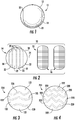
- Figures 1 and 2 illustrate an example tennis ball 10 which utilizes material shift lines to provide a customized COR and/or other ball performance characteristics.
- Figure 1 is a perspective view of tennis ball 10 while Figure 2 is an exploded view of tennis ball 10.
- tennis ball 10 comprises outer textile layer 12 and core 14.
- Outer textile layer 12 comprises at least one layer of fabric material secured over and about core 14.
- outer textile layer 12 comprises two inter-nested, ovular or stadium shaped panels 16.
- the outer textile layer 12 can comprise a pair of inter-nested dog-bone-shaped panels 16 of textile material bonded to core 14, along seams 18 in other implementations, outer textile layer 12 may be provided by panels having other shapes.
- textile layer 12 may be formed by fibers not provided in the form of panels, but which are individually joined or bonded to core 14.
- tennis ball 10 may be formed by bathing or coating core 14 in an adhesive, such as a synthetic or natural rubber adhesive.
- an adhesive such as a synthetic or natural rubber adhesive.
- the outer edges of at least one of the two stadium (or dog-bone) shaped panels 16 of textile material are also coated with an adhesive, such as a synthetic or natural rubber adhesive.
- the panels 16 are then applied over and to the core 14 with the edges of the panels 16 in abutment or close proximity, while the adhesives are in an adhesive state to form the tennis ball shown in Figure 1 .
- the adhesive is then allowed to dry or cure.
- Core 14 comprises a hollow spherical structure having a spherical wall formed from, for example, a rubber or rubber-like material.
- core 14 is formed from two semi spherical halves or half shells 18 which are molded and joined or bonded together with an adhesive, such as a natural rubber or synthetic rubber adhesive.
- the two semi-spherical halves or half shells 18 are joined in a pressure chamber so the interior of the joined halves is pressurized.
- a pressurized tennis ball 10 may have an internal pressure of approximately 69 to 103 kPa (10 to 15 psi). In other implementations, the pressure can be below 69 kPa (10 psi).
- core 14 may be formed in other manners.
- core 14 may additionally incorporate a valve that facilitates pressurization of the interior of core 14.
- the interior surface of the hollow core 14 comprises material shift lines 20 which are spaced apart by intermediate regions 22.
- Material shift lines 20 extend along the interior surface of the wall or walls of core 14 and constitute regions where the material or materials of core 14 have been shifted such that material shift lines 20 have a distinct thickness as compared to the thickness through any of regions 22 of the core 14.
- material shift lines 20 constitute regions where material has been shifted from regions 22 such that material shift lines 20 have a greater thickness as compared to regions 22. Because the thickness of regions 22 is thinner, the effective thickness of such a tennis ball would be reduced.
- material shift lines 20 may comprise projections, ridges, ribs or bands of material.
- material shift lines 20 comprise regions where material has been removed, or from which material has been shifted to regions 22, such that material shift lines 20 have a lesser thickness as compared to regions 22. Because the thickness of regions 22 is thicker, the effective thickness of such a tennis ball would be increased.
- the shift lines 20 may comprise grooves or channels recessed into the walls of core 14.
- material shift lines 20 continuously extend around the axis 24 of core 14. Each material shift line 20 extends 360° about axis 24. In the example illustrated, material shift lines 20 extend parallel to one another. In the example illustrated, material shift lines cover or extend across no greater than 5 percent of the interior circumferential surface of core 14. In other implementations, material shift lines 20 may cover other extents of the interior surface of core 14, may have other configurations, or may intermittently extend along or about the interior surface of core 14.
- the tennis ball is produced in accordance with specifications of the U.S. Tennis Association (USTA.) and the International Tennis Federation (ITF).
- U.S. Tennis Association U.S. Tennis Association
- IF International Tennis Federation
- the tennis ball can be produced in accordance with the following specifications.
- Figures 3 and 4 illustrate cores 114 and 214 that may be utilized in place of core 14 in tennis ball 10.
- Core 114 is similar to core 14 except that core 114 comprises material shift lines 120 spaced by intermediate regions 122.
- Material shift lines 120 are similar to material shift lines 20 except that material shift lines 120 are not in the form of straight parallel lines about an axis of the core, but instead comprise wavy or sinusoidal lines.
- the wavy material shift lines 120 are illustrated as being in phase with one another, in other implementations, in other implementations, the wavy material shift lines 120 may be out of phase with one another.
- the wavy material shift lines 120 may extend perpendicular to one another or may cross one another.
- the wavy material shift lines 120 may comprise wavy spaced segments that collectively intermittently extend about the interior surface of core 114.
- Core 214 is similar to core 14 except that core 214 comprises material shift lines 220 spaced by intermediate regions 222.
- Material shift lines 220 are similar to material shift lines 20 except that material shift lines 220 are not in the form of straight parallel lines about an axis of the core, but instead comprise zigzag or jagged lines.
- the zigzag material shift lines 220 are illustrated as being in phase with one another, in other implementations, in other implementations, the zigzag material shift lines 220 may be out of phase with one another. In some implementations, the zigzag material shift lines 220 may extend perpendicular to one another or may cross one another.
- the zigzag material shift lines 220 may comprise zigzag spaced segments that collectively intermittently extend about the interior surface of core 214.
- material shift lines 120 and 220 may comprise regions of greater thickness as compared to the remaining intermediate portions 122, 222 to decrease the effective thickness of the core 114, 214 or regions of lesser thickness as compared to the remaining intermediate portions 122 and 222 to increase the effective thickness of core 114, 214.
- FIGs 5-9 illustrate an example core 314 for use in tennis ball 10 in place of core 14.
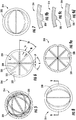
- Core 314 is similar to core 14 except that core 314 is specifically illustrated as comprising material shift lines in the form of bands 320.
- Bands 320 comprise regions along the interior hollow surface 324 of core 314 that have thickness T b that is greater than the thickness T e , the "effective thickness" of core 314 corresponding to the thickness of the intermediate regions 322 spacing and extending between bands 320.
- bands 320 form a vertical pattern of bands along the interior surface 324 of core 314.
- core 314 has a diameter D of approximately 62.7 mm and the interior surface 324 has a radius R of 27.6 mm.
- bands 320 are angularly spaced from another by a spacing angle SA of 45°. In other implementations, core 314 may have other configurations and dimensions.
- bands 320 are illustrated as being pointed or generally triangular in shape ( Figure 9 ), having an angle A of 90° and a base B of 3 mm in one implementation, in other implementations, bands 320 may have other shapes and sizes.
- bands 320 may have a rectangular or square cross sectional shape ( Figure 9b ), curved or semi spherical cross-sectional shapes ( Figure 9c ), or trapezoidal or polygonal shapes ( Figure 9d ).
- the bands can have a shape that is triangular, rectangular, trapezoidal, polygonal, hemi-spherically shaped, hemi-ovular shaped, rounded, irregular or a combination thereof.
- bands 320 provide core 314 with a reduction in its effective thickness of 10%.
- FIGS 10-15 illustrate an example core 414 that may be utilized in place of core 14 as part of tennis ball 10 described above.
- Core 414 is similar to core 314 except that core 414 is specifically illustrated as comprising material shift lines in the form of bands 420.
- Bands 420 are similar to bands 320 in that bands 420 comprise regions along the interior hollow surface 424 of core 414 that have thickness that is greater than the thickness, the "effective thickness" of core 414 in the intermediate regions 422 spacing and extending between bands 420.
- Bands 420 have a different pattern within the interior of core 414. In the example illustrated, bands 420 form a trapezoidal pattern of bands along the interior surface 424 of core 414. In one implementation, bands 420 provide core 414 with a reduction in its effective thickness of 10%.
- FIGS 16-20 illustrate an example core 514 that may be utilized in place of core 14 as part of tennis ball 10 described above.
- Core 514 is similar to core 414 except that core 414 is specifically illustrated as comprising material shift lines in the form of bands 520.
- Bands 520 are similar to bands 420 in that bands 520 comprise regions along the interior hollow surface 524 of core 514 that have thickness that is greater than the thickness, the "effective thickness" of core 514 in the intermediate regions 522 spacing and extending between bands 520.
- Bands 520 are larger or wider such that bands 520 provide a further reduced effective thickness of core 514 as measured in those regions 522 between bands 520.
- Bands 520 have a different pattern within the interior of core 514. In the example illustrated, bands 520 form a trapezoidal pattern of bands along the interior surface 524 of core 514. In one implementation, bands 520 provide core 514 with a reduction in its effective thickness of 20%.
- FIG. 21-25 illustrate an example core 614 that may be utilized in place of core 14 as part of tennis ball 10 described above.
- Core 614 is similar to core 514 except that core 614 is specifically illustrated as comprising material shift lines in the form of bands 620.
- Bands 620 are similar to bands 520 in that bands 620 comprise regions along the interior hollow surface 624 of core 614 that have thickness that is greater than the thickness, the "effective thickness" of core 614 in the intermediate regions 622 spacing and extending between bands 620.
- Bands 620 have a different pattern within the interior of core 614. In the example illustrated, bands 620 form a trapezoidal pattern of bands along the interior surface 624 of core 614. In one implementation, bands 620 provide core 614 with a reduction in its effective thickness of 20%.
- bands 320, 420, 520 and 620 provided on the interior surface of the tennis ball cores may have varying thicknesses and widths to provide different degrees of reduction of the effective thickness of the core to reduce the COR of the tennis ball to various extents.
- bands can provide core with a reduction in its effective thickness of 30%, 40% or 50%.
- other amounts of effective thickness reduction of the core can be used.
- the volume decrease is to be achieved is based upon the lower "effective" half-shell or core thickness transferred to continuous "bands" extending outward from the inner surface of the core.
- the volume to be shifted is dependent upon the degree to which the "effective thickness" of the core is adjusted.
- the volume of material that may be shifted to such bands in various example tennis ball cores is illustrated as follows:
- a pressureless tennis ball may be molded using a half-shell or core that has an outer diameter of approximately 62.7 mm and an inner diameter of approximately 54.7 mm. This results in a thickness of the half-shell of approximately 4.0 mm and an overall material volume of approximately 43.36 cm .
- the above table shows the amount of volume to be transferred into the "bands" extending outward from the inner surface of the half-shell for each 10% reduction in the effective thickness of the core of a Pressureless Tennis Ball. Reducing the thickness of the core beyond 50% can negatively affect the impact durability of core.
- a pressurized tennis ball is molded using a half-shell or core that has an outer diameter of approximately 61.2 mm and an inner diameter of approximately 54.2 mm. This results in a thickness of the core of approximately 3.5 mm and an overall material volume of 36.65 cm 3 .
- Adjusting the half-shell to a lesser thickness results in the need to transfer volume to the outward extending "bands" as follows: Table 2: Volume Displacement (transferred to "bands") based upon Reduction of Effective Thickness - Standard (Pressurized) Tennis Ball Outer Diameter (mm) Inner Diameter (mm) Effective Thickness (mm) Volume Displaced (cm3) ⁇ Volume Displaced (%) Thickness Change % 61.2 54.2 3.5 0 0% -- 61.2 54.9 3.15 3.3 8.9% 10% 61.2 55.6 2.8 6.6 18.1% 20% 61.2 56.3 2.45 10.1 27.5% 30% 61.2 57.0 2.1 13.6 37.1% 40% 61.2 57.7 1.75 17.2 47.7% 50%
- the above table shows the amount of volume to be transferred into the "bands" extending outward from the inner surface of the half-shell for each 10% reduction in the effective thickness of the core of a standard (pressurized) Tennis Ball. Reducing the thickness of the core beyond 50% can negatively affect the impact durability of core.
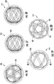
- the "effective thickness" of the core 714, 814 and 914 can be increased by creating a thicker thickness of the shell or wall thickness of the core.
- the weight or density of the core can be maintained by defining a plurality of channels or grooves 720, 820 and 920 in the inner surface of the core 714, 814 and 914, respectively.
- the material of the core 714, 814 and 914 is shifted from the channels 720, 820 and 920 to regions 722, 822 and 922 of the core between the channels 720, 820 and 920.
- the channels 720 of core 714 are, in this example, generally V-shaped or generally triangular.
- the channels 820 and 920 are generally trapezoidal in shape.
- the channels 720 are angularly spaced from another by a spacing angle SA of 45°.
- the channels 820 are angularly spaced from another by a spacing angle SA of 60°.
- the channels 920 are arranged in a different configuration.
- the channels can be generally U-shaped, hemi-spherically shaped, hemi-ovular shaped, polygonal shaped, rounded, irregular and combinations thereof.
- channels 720 and 820 can have other configurations, in other spacing angles, other numbers, other shapes and/or other sizes.
- the volume increase based upon the thicker "effective" half-shell or core is transferred from continuous "channels" extending inward from the inner surface of the half-shell.
- the volume to be shifted is dependent upon the degree to which the "effective thickness" of the half-shell is adjusted.
- the volume of material that has to be adjusted is illustrated as follows:
- a pressureless tennis ball is molded using a half-shell that has an outer diameter of approximately 62.7 mm and an inner diameter of approximately 54.7 mm. This results in a thickness of the half-shell of approximately 4.0 mm and an overall material volume of 43.36 cm 3 .
- the above table shows the amount of volume transferred into the "channels" extending inward from the inner surface of the half-shell for each 10% increase in the effective thickness of the core of a Pressureless Tennis Ball. Increase of the thickness of the core by greater than 30% may result in a necessary removal of an unacceptable high amount of volume that would result in "channels" that are larger than could be incorporated into the half-shell.
- a tennis ball is molded using a half-shell that has an outer diameter of approximately 61.2 mm and an inner diameter of approximately 54.2 mm. This results in a thickness of the half-shell of approximately 3.5 mm and an overall material volume of 36.65 cm 3 .
- Adjusting the half-shell or core to a greater thickness results in the transfer of volume or mass from the area of the channels as follows: Table 4: Volume Displacement (transferred to "channels") based upon Increase in Effective Thickness - Standard (Pressurized) Tennis Ball Outer Diameter (mm) Inner Diameter (mm) Effective Thickness (mm) Volume Displaced (cm3) ⁇ Volume Displaced (%) Thickness Change % 61.2 54.2 3.5 0 0% -- 61.2 53.5 3.85 3.2 8.7% 10% 61.2 52.8 4.2 6.3 17.2% 20% 61.2 52.1 4.55 9.3 25.4% 30%
- the above table shows the amount of volume transferred into the "channels" extending inward from the inner surface of the half-shell for each 10% increase in the effective thickness of the core of a Standard (Pressurized) Tennis Ball. Increase of the thickness of the core by greater than 30% may result in a necessary removal of an unacceptable high amount of volume that would result in "channels" that are larger than could be incorporated into the half-shell.
- Core 514 (shown in Figures 18-20 ) was molded with a band pattern comprising a symmetrical trapezoidal band pattern resulting in a half-shell having the following properties:
- Core 714 (shown in Figure 26 ) was molded with a channel pattern comprising vertical or generally V-shaped channels resulting in a half shell having the following properties:
- Core 814 (shown in Figure 27 ) was molded with a channel pattern comprising an offset trapezoidal channel pattern resulting in a half-shell having the following properties:
- Core 914 (shown in Figure 28 ) was molded with a channel pattern comprising a symmetrical trapezoidal channel pattern resulting in a half-shell having the following properties:
- Pressureless tennis balls were molded using the tooling as defined above using a standard pressureless ball compound as follows: Pressureless Ball Compound No. Ingredient SP.GR Experiment IV Volume phr. Wt.(g) 1 NR#1 0.93 20 9.000 9.68 2 BR-01 0.91 80 36.000 39.56 3 Rigidex H5818 0.916 20 9.000 9.83 4 HiSil255 2 8 3.600 1.80 5 ZnO -active 5.6 10 4.500 0.80 6 CLAY 2.6 20 9.000 3.46 7 DPG 1.18 0.5 0.225 0.19 8 PTA 1.33 0.5 0.225 0.17 Total 159.00 71.550 65.488 Chemical mixing 1 DM 0.154 1.46 0.657 4.27 2 DPG 1.18 0.59 0.266 0.23 3 CBS 1.36 0.512 0.230 0.17 4 S-25 2.07 5.56 2.502 1.21 Total 1.054 75.205 71.357
- Pressureless tennis balls molded with continuous "bands” or “channels” incorporated in the half shell were tested and compared to a standard pressureless tennis ball formed of the same material composition.
- the adjustment of the tennis ball thickness to a thinner effective core is far easier to perform, as the volume of material that can be shifted to the "bands" that will extend outward from the half-shell is significantly greater than the amount of volume that can be shifted to "channels" that will extend inward from the inner surface of the tennis ball core.
- the degree of which the effective thickness of the core can be increased is limited as the corresponding volume would need to be incorporated as inward-extending channels. Any level of increase of the effective thickness over about 30% results in inward-extending channels that would result in core/shell thickness between the innermost portion of the inward-extending channels and the outer surface of the half-shell that would be insufficiently thick and result in impact durability issues for the molded tennis ball.
- a tennis ball may include a spherical hollow core having an inner surface comprising material shift lines, and a textile outer layer over and about the core.
- Implementations of the present invention may include one or more of the following elements.
- the material shift lines may be channels extending into the inner surface forming a plurality of regions of reduced core thickness. Portions of the spherical hollow core between the channels may have a thickness of at least 4 mm. Portions of the spherical hollow core between the channels may have a thickness of at least 4.4 mm.
- the channels may have a collective volume of at least 2 cm 3 .
- An interior volume of the spherical hollow core may be pressurized to a pressure of at least 69 kPa (10 psi) and portions of the spherical hollow core between the channels can have a thickness of at least 3.7 mm.
- An interior volume of the spherical hollow core may be pressurized to a pressure of at least 69 kPa (10 psi) and the channels can have a collective volume of at least 3 cm 3 .
- the channels may cover no greater than about 48% of a total inner surface area of the spherical hollow core. At least one of the channels may extend 360 degrees about the inner surface of the spherical hollow core.
- the channels may have a pattern selected from a group of patterns consisting of; a vertical pattern wherein the channels intersect at opposite poles; an offset pattern; and a symmetrical pattern.
- the material shift lines may include bands projecting from the inner surface forming a plurality of regions of increased core thickness. Portions of the spherical hollow core between the bands may have a thickness of no greater than 3.6 mm. Portions of the spherical hollow core between the bands may have a thickness of no greater than 3.2 mm.
- the bands may have a collective volume of at least 3 cm 3 .
- the bands may have a collective volume of at least 8 % of a total material volume of the spherical hollow core.
- An interior volume of the spherical hollow core may have an internal pressure of less than 34 kPa (5 psi) and portions of the spherical hollow core between the bands may have a thickness of less than 3.7 mm.
- An interior volume of the spherical hollow core may have an internal pressure of less than 34 kPa (5 psi) and the portions of the spherical hollow core between the bands may have a thickness of less than 3.3 mm.
- An interior volume of the spherical hollow core may have an internal pressure of less than 34 kPa (5 psi) and the bands may have a collective volume of at least 3.3 cm.
- the bands may have a collective volume of at least 8% of a total material volume of the spherical hollow core.
- the bands may cover no greater than about 51 % of a total inner surface area of the spherical hollow core. At least one of the bands may extend 360 degrees about the inner surface of the spherical hollow core.
- the bands may have a pattern selected from a group of patterns consisting of: a vertical pattern wherein the bands intersect at opposite poles; an offset pattern; and a symmetrical pattern.
- the channels or the bands may have a cross-sectional shape selected from the group consisting of generally V-shaped, generally U-shaped, hemi-spherically shaped, hemi-ovular shaped, polygonal shaped, rounded, irregular and combinations thereof.
Landscapes
- Health & Medical Sciences (AREA)
- General Health & Medical Sciences (AREA)
- Physical Education & Sports Medicine (AREA)
- Laminated Bodies (AREA)
- Compositions Of Macromolecular Compounds (AREA)
Description
- Tennis balls typically include an elastomeric or rubber-like core about which two dog-bone shaped panels of felt or other textile is bonded. Many tennis balls are pressurized to enhance rebound or bounce performance.
-
-
Figure 1 is a side view of an example tennis ball. -
Figure 2 is an exploded view of another example tennis ball. -
Figure 3 is a side view of a core of tennis ball including material shift lines in accordance with an implementation of the present invention. -
Figure 4 is a side view of a core of tennis ball including material shift lines in accordance with another implementation of the present invention. -
Figure 5 is a first cross-sectional view of a core of a tennis ball including material shift lines in accordance with another implementation of the present invention. -
Figure 6 is an end side view of the core ofFigure 5 with the material shift lines shown in phantom. -
Figure 7 is a first side view of the core ofFigure 5 with the material shift lines shown in phantom. -
Figure 8 is a second side view of the core ofFigure 5 with the material shift lines shown in phantom. -
Figure 9 is a second cross-sectional view of the core taken along line 9 - 9 ofFigure 8 . -
Figures 9b through 9d are fragmentary sectional views of alternative implementations a portion of the tennis ball core ofFigure 9 . -
Figure 10 is a cross-sectional view of a core of a tennis ball including material shift lines in accordance with another implementation of the present invention.. -
Figure 11 is an end side view of the core ofFigure 10 with the material shift lines shown in phantom. -
Figure 12 is a first side view of the core ofFigure 10 with the material shift lines shown in phantom. -
Figure 13 is a second side view of the core ofFigure 10 with the material shift lines shown in phantom. -
Figure 14 is a cross-sectional view of a portion of the core taken along line 14 - 14 ofFigure 12 . -
Figure 15 is a cross-sectional view of the core taken about line 15 - 15 ofFigure 13 . -
Figure 16 is a first side view of a core of a tennis ball with material shift lines shown in phantom in accordance with another implementation of the present invention. -
Figure 17 is a second side view of the core ofFigure 16 with the material shift lines shown in phantom. -
Figure 18 is a third side view of the core ofFigure 16 with the material shift lines shown in phantom. -
Figure 19 is a fourth view of a portion of the core ofFigure 16 with the material shift lines shown in phantom. -
Figure 20 is a cross-sectional view of the core taken along line 20 - 20 ofFigure 19 . -
Figure 21 is a first side view of a core of a tennis ball with material shift lines shown in phantom in accordance with another implementation of the present invention. -
Figure 22 is a second side view of the core ofFigure 21 with the material shift lines shown in phantom. -
Figure 23 is a third side view of the core ofFigure 21 with the material shift lines shown in phantom. -
Figure 24 is a fourth view of a portion of the core ofFigure 21 with the material shift lines shown in phantom. -
Figure 25 is a cross-sectional view of the core taken along line 25 - 25 ofFigure 24 . -
Figure 26 is a cross-sectional view of a core of a tennis ball including material shift lines in accordance with another implementation of the present invention. -
Figure 27 is a cross-sectional view of a core of a tennis ball including material shift lines in accordance with another implementation of the present invention. -
Figure 28 is a cross-sectional view of a core of a tennis ball including material shift lines in accordance with another implementation of the present invention. - Disclosed herein are examples of tennis balls that have customizable performance characteristics, with the invention being described in the appended claims. The example tennis balls may have customizable coefficient of restitution (COR) or rebound characteristics best suited to a tennis player's or an organization's preferences or player's skill level. For example, some tennis players may prefer a slower tennis ball or a ball that does not bounce as high or as fast. Such slower balls may be easier for a younger or lesser experienced tennis player to keep in play. Other tennis players may prefer a faster tennis ball or a ball that bounces higher.
US 398,558 discloses an example of a tennis ball.US 5,558,325 discloses an example of a hollow-rubber play ball.EP 0,576,233 discloses an example of a stitch-less fabric covered ball. - The example tennis balls disclosed herein facilitate customization of the COR or rebound characteristics of a tennis ball while reducing or eliminating any changes to the weight, feel, sound of impact and other characteristics of the tennis ball. The example tennis balls comprise material shift lines on the inner surface of the core of the tennis balls, the core being spherical and hollow and consisting of two joined semi-spherical halves, with the spherical hollow core having an interior volume with an internal pressure of less than 34.5 kPa (5 psi). Such material shift lines constitute regions where material forming the wall of the core has been shifted such that the remaining portions of the core wall have an altered thickness different than that of the material shift lines. Those remaining portions of the core wall having the altered thickness form a majority of the core wall and provide the core with its overall "effective thickness". Such material shift lines allow the material of the core wall to be shifted to the remaining portions to increase the effective thickness of the core or to be shifted from remaining portions to decrease the effective thickness of the core, all while maintaining the overall weight of the core and the overall size of the core. Providing a greater effective thickness increases COR or rebound characteristics of the tennis ball. Providing a smaller effective thickness also increases the COR or rebound characteristics and the stiffness or resistance to deformation of the tennis ball. A textile outer layer is over and about the core, being directly bonded to the entire exterior surface of the spherical hollow core, without interruption, by an adhesive layer. The textile outer layer comprises two panels joined by adhesively coated edges.
- In some implementations, material shift lines may comprise ribs or bands along and projecting from the inner surface of the core. The bands of material on the inner surface of the tennis ball core may allow for material from remaining portions of the core wall to be shifted to such bands, reducing the thickness of the remaining portions of the core. Because the remaining portions of the core wall may constitute a majority of the core, the "effective thickness", the thickness of the core wall throughout a majority of the core, may be reduced. As noted above, this lower thickness or lower "effective thickness" throughout a majority of the tennis ball may increase the COR or rebound characteristics and increase the stiffness or resistance to deformation of the tennis ball. In some implementations, the increased "effective thickness", enhanced COR and increased stiffness may be used to enhance the performance of lower pressure or pressureless tennis balls.
- In some implementations, the material shift lines may comprise grooves or channels along and recessed into the inner surface of the core, and may form a plurality of regions of reduced core thickness. The channels on the inner surface of the tennis ball core may allow material that would otherwise fill the channels to be distributed across remaining portions of the core or core wall. Because the remaining portions of the core wall may constitute a majority of the core, the "effective thickness", the thickness of the core wall throughout a majority of the core may be increased. As noted above, the increased thickness or increased "effective thickness" throughout a majority of the tennis ball increases the COR or rebound characteristics of the tennis ball. In some implementations, the increased "effective thickness" and enhanced COR may be used to enhance the performance of lower pressure or pressureless tennis balls.
-
Figures 1 and 2 illustrate anexample tennis ball 10 which utilizes material shift lines to provide a customized COR and/or other ball performance characteristics.Figure 1 is a perspective view oftennis ball 10 whileFigure 2 is an exploded view oftennis ball 10. As shown byFigures 1 and 2 ,tennis ball 10 comprisesouter textile layer 12 andcore 14.Outer textile layer 12 comprises at least one layer of fabric material secured over and aboutcore 14. As shown byFigure 2 , in one implementation,outer textile layer 12 comprises two inter-nested, ovular or stadium shapedpanels 16. In another implementation, theouter textile layer 12 can comprise a pair of inter-nested dog-bone-shapedpanels 16 of textile material bonded tocore 14, along seams 18 in other implementations,outer textile layer 12 may be provided by panels having other shapes. In some implementations,textile layer 12 may be formed by fibers not provided in the form of panels, but which are individually joined or bonded tocore 14. - In one implementation,
tennis ball 10 may be formed by bathing orcoating core 14 in an adhesive, such as a synthetic or natural rubber adhesive. In such an implementation, the outer edges of at least one of the two stadium (or dog-bone) shapedpanels 16 of textile material are also coated with an adhesive, such as a synthetic or natural rubber adhesive. Thepanels 16 are then applied over and to the core 14 with the edges of thepanels 16 in abutment or close proximity, while the adhesives are in an adhesive state to form the tennis ball shown inFigure 1 . The adhesive is then allowed to dry or cure. -
Core 14 comprises a hollow spherical structure having a spherical wall formed from, for example, a rubber or rubber-like material. In one implementation,core 14 is formed from two semi spherical halves orhalf shells 18 which are molded and joined or bonded together with an adhesive, such as a natural rubber or synthetic rubber adhesive. In one implementation, the two semi-spherical halves orhalf shells 18 are joined in a pressure chamber so the interior of the joined halves is pressurized. Apressurized tennis ball 10 may have an internal pressure of approximately 69 to 103 kPa (10 to 15 psi). In other implementations, the pressure can be below 69 kPa (10 psi). In other implementations,core 14 may be formed in other manners. In other implementations,core 14 may additionally incorporate a valve that facilitates pressurization of the interior ofcore 14. - As further illustrated by broken lines in
Figure 2 , the interior surface of thehollow core 14 comprisesmaterial shift lines 20 which are spaced apart byintermediate regions 22. Material shift lines 20 extend along the interior surface of the wall or walls ofcore 14 and constitute regions where the material or materials ofcore 14 have been shifted such thatmaterial shift lines 20 have a distinct thickness as compared to the thickness through any ofregions 22 of thecore 14. In one implementation,material shift lines 20 constitute regions where material has been shifted fromregions 22 such thatmaterial shift lines 20 have a greater thickness as compared toregions 22. Because the thickness ofregions 22 is thinner, the effective thickness of such a tennis ball would be reduced. For example, in one implementation,material shift lines 20 may comprise projections, ridges, ribs or bands of material. - In another implementation,
material shift lines 20 comprise regions where material has been removed, or from which material has been shifted toregions 22, such thatmaterial shift lines 20 have a lesser thickness as compared toregions 22. Because the thickness ofregions 22 is thicker, the effective thickness of such a tennis ball would be increased. For example, in one implementation, the shift lines 20 may comprise grooves or channels recessed into the walls ofcore 14. - In the example illustrated,
material shift lines 20 continuously extend around theaxis 24 ofcore 14. Eachmaterial shift line 20 extends 360° aboutaxis 24. In the example illustrated,material shift lines 20 extend parallel to one another. In the example illustrated, material shift lines cover or extend across no greater than 5 percent of the interior circumferential surface ofcore 14. In other implementations,material shift lines 20 may cover other extents of the interior surface ofcore 14, may have other configurations, or may intermittently extend along or about the interior surface ofcore 14. - In many implementations, the tennis ball is produced in accordance with specifications of the U.S. Tennis Association (USTA.) and the International Tennis Federation (ITF). For example, the tennis ball can be produced in accordance with the following specifications.
-
- Size:
- The size of the ball is tested using two ring gauges having internal diameter of 6.54 cm (2.54 inches) and 6.86 cm (2.70 inches). The tennis ball, when tested, must pass through the larger ring gauge and be unable to pass through the smaller ring gauge to meet the size requirements.
- Weight:
- The weight of the ball is measured on a scale that is calibrated to +/- 0.01 grams. The acceptable weight of the tennis ball is between 56.0 grams and 59.4 grams.
- Deformation:
- The deformation of the tennis ball is measured using either a Stevens Machine (manually operated) or an automatic compression machine. The deformation of the ball is measured under a load of 80.07 N (18 lb.) after a 15.57 N (3.5 lb.) preload has been applied. The deformation of the ball is required to be between 0.56 cm (0.220 inches) and 0.74 cm (0.291 inches).
- Rebound:
- The rebound of the ball is measured by dropping the ball vertically from a height of 254 cm (100 inches) and measuring the rebound of the tennis ball. The rebound height of the tennis ball should be from 135 cm (53 inches) to 147 cm (58 inches).
-
Figures 3 and 4 illustratecores core 14 intennis ball 10.Core 114 is similar tocore 14 except thatcore 114 comprisesmaterial shift lines 120 spaced byintermediate regions 122.Material shift lines 120 are similar tomaterial shift lines 20 except thatmaterial shift lines 120 are not in the form of straight parallel lines about an axis of the core, but instead comprise wavy or sinusoidal lines. Although the wavymaterial shift lines 120 are illustrated as being in phase with one another, in other implementations, in other implementations, the wavymaterial shift lines 120 may be out of phase with one another. In some implementations, the wavymaterial shift lines 120 may extend perpendicular to one another or may cross one another. In other implementations, the wavymaterial shift lines 120 may comprise wavy spaced segments that collectively intermittently extend about the interior surface ofcore 114. -
Core 214 is similar tocore 14 except thatcore 214 comprisesmaterial shift lines 220 spaced byintermediate regions 222.Material shift lines 220 are similar tomaterial shift lines 20 except thatmaterial shift lines 220 are not in the form of straight parallel lines about an axis of the core, but instead comprise zigzag or jagged lines. Although the zigzagmaterial shift lines 220 are illustrated as being in phase with one another, in other implementations, in other implementations, the zigzagmaterial shift lines 220 may be out of phase with one another. In some implementations, the zigzagmaterial shift lines 220 may extend perpendicular to one another or may cross one another. In other implementations, the zigzagmaterial shift lines 220 may comprise zigzag spaced segments that collectively intermittently extend about the interior surface ofcore 214. As discussed above with respect tomaterial shift lines 20,material shift lines intermediate portions core intermediate portions core -
Figures 5-9 illustrate anexample core 314 for use intennis ball 10 in place ofcore 14.Core 314 is similar tocore 14 except thatcore 314 is specifically illustrated as comprising material shift lines in the form ofbands 320.Bands 320 comprise regions along the interiorhollow surface 324 ofcore 314 that have thickness Tb that is greater than the thickness Te, the "effective thickness" ofcore 314 corresponding to the thickness of theintermediate regions 322 spacing and extending betweenbands 320. In the example illustrated,bands 320 form a vertical pattern of bands along theinterior surface 324 ofcore 314. - In the example illustrated,
core 314 has a diameter D of approximately 62.7 mm and theinterior surface 324 has a radius R of 27.6 mm. In the example illustrated,bands 320 are angularly spaced from another by a spacing angle SA of 45°. In other implementations,core 314 may have other configurations and dimensions. Althoughbands 320 are illustrated as being pointed or generally triangular in shape (Figure 9 ), having an angle A of 90° and a base B of 3 mm in one implementation, in other implementations,bands 320 may have other shapes and sizes. For example, in other implementations,bands 320 may have a rectangular or square cross sectional shape (Figure 9b ), curved or semi spherical cross-sectional shapes (Figure 9c ), or trapezoidal or polygonal shapes (Figure 9d ). In other implementations, the bands can have a shape that is triangular, rectangular, trapezoidal, polygonal, hemi-spherically shaped, hemi-ovular shaped, rounded, irregular or a combination thereof. In one implementation,bands 320 providecore 314 with a reduction in its effective thickness of 10%. -
Figures 10-15 illustrate anexample core 414 that may be utilized in place ofcore 14 as part oftennis ball 10 described above.Core 414 is similar tocore 314 except thatcore 414 is specifically illustrated as comprising material shift lines in the form ofbands 420.Bands 420 are similar tobands 320 in thatbands 420 comprise regions along the interiorhollow surface 424 ofcore 414 that have thickness that is greater than the thickness, the "effective thickness" ofcore 414 in the intermediate regions 422 spacing and extending betweenbands 420.Bands 420 have a different pattern within the interior ofcore 414. In the example illustrated,bands 420 form a trapezoidal pattern of bands along theinterior surface 424 ofcore 414. In one implementation,bands 420 providecore 414 with a reduction in its effective thickness of 10%. -
Figures 16-20 illustrate anexample core 514 that may be utilized in place ofcore 14 as part oftennis ball 10 described above.Core 514 is similar tocore 414 except thatcore 414 is specifically illustrated as comprising material shift lines in the form ofbands 520.Bands 520 are similar tobands 420 in thatbands 520 comprise regions along the interiorhollow surface 524 ofcore 514 that have thickness that is greater than the thickness, the "effective thickness" ofcore 514 in theintermediate regions 522 spacing and extending betweenbands 520.Bands 520 are larger or wider such thatbands 520 provide a further reduced effective thickness ofcore 514 as measured in thoseregions 522 betweenbands 520.Bands 520 have a different pattern within the interior ofcore 514. In the example illustrated,bands 520 form a trapezoidal pattern of bands along theinterior surface 524 ofcore 514. In one implementation,bands 520 providecore 514 with a reduction in its effective thickness of 20%. -
Figures 21-25 illustrate anexample core 614 that may be utilized in place ofcore 14 as part oftennis ball 10 described above.Core 614 is similar tocore 514 except thatcore 614 is specifically illustrated as comprising material shift lines in the form ofbands 620.Bands 620 are similar tobands 520 in thatbands 620 comprise regions along the interiorhollow surface 624 ofcore 614 that have thickness that is greater than the thickness, the "effective thickness" ofcore 614 in theintermediate regions 622 spacing and extending betweenbands 620.Bands 620 have a different pattern within the interior ofcore 614. In the example illustrated,bands 620 form a trapezoidal pattern of bands along theinterior surface 624 ofcore 614. In one implementation,bands 620 providecore 614 with a reduction in its effective thickness of 20%. - The above patterns of
bands - Pressureless Tennis Ball: A pressureless tennis ball may be molded using a half-shell or core that has an outer diameter of approximately 62.7 mm and an inner diameter of approximately 54.7 mm. This results in a thickness of the half-shell of approximately 4.0 mm and an overall material volume of approximately 43.36 cm . Adjusting the half-shell to a lesser thickness results in the transfer of volume to the outward extending "bands" as follows:
Table 1: Volume Displacement (transferred to "bands") based upon Reduction of Effective Thickness - Pressureless Tennis Ball Outer Diameter (mm) Inner Diameter (mm) Effective Thickness (mm) Volume Displaced (cm3) Δ Volume Displaced (%) Thickness Change % 62.7 54.7 4.0 0 -- -- 62.7 55.5 3.6 3.8 8.8% 10% 62.7 56.3 3.2 7.7 17.9% 20% 62.7 57.1 2.8 11.8 27.2% 30% 62.7 57.9 2.4 15.9 36.8% 40% 62.7 58.7 2.0 20.2 46.6% 50% - The above table shows the amount of volume to be transferred into the "bands" extending outward from the inner surface of the half-shell for each 10% reduction in the effective thickness of the core of a Pressureless Tennis Ball. Reducing the thickness of the core beyond 50% can negatively affect the impact durability of core.
- Pressurized Tennis Ball: A pressurized tennis ball is molded using a half-shell or core that has an outer diameter of approximately 61.2 mm and an inner diameter of approximately 54.2 mm. This results in a thickness of the core of approximately 3.5 mm and an overall material volume of 36.65 cm3. Adjusting the half-shell to a lesser thickness results in the need to transfer volume to the outward extending "bands" as follows:
Table 2: Volume Displacement (transferred to "bands") based upon Reduction of Effective Thickness - Standard (Pressurized) Tennis Ball Outer Diameter (mm) Inner Diameter (mm) Effective Thickness (mm) Volume Displaced (cm3) Δ Volume Displaced (%) Thickness Change % 61.2 54.2 3.5 0 0% -- 61.2 54.9 3.15 3.3 8.9% 10% 61.2 55.6 2.8 6.6 18.1% 20% 61.2 56.3 2.45 10.1 27.5% 30% 61.2 57.0 2.1 13.6 37.1% 40% 61.2 57.7 1.75 17.2 47.7% 50% - The above table shows the amount of volume to be transferred into the "bands" extending outward from the inner surface of the half-shell for each 10% reduction in the effective thickness of the core of a standard (pressurized) Tennis Ball. Reducing the thickness of the core beyond 50% can negatively affect the impact durability of core.
- In other implementations, such as the implementations of
Figures 26-28 , the "effective thickness" of thecore grooves core core channels regions channels channels 720 ofcore 714 are, in this example, generally V-shaped or generally triangular. Thechannels Figure 26 , thechannels 720 are angularly spaced from another by a spacing angle SA of 45°. In the implementation ofFigure 27 , thechannels 820 are angularly spaced from another by a spacing angle SA of 60°. In the implementation ofFigure 28 , thechannels 920 are arranged in a different configuration. In other implementations, the channels can be generally U-shaped, hemi-spherically shaped, hemi-ovular shaped, polygonal shaped, rounded, irregular and combinations thereof. In other implementations,channels - For increasing the effective thickness of the tennis ball half-shell, the volume increase based upon the thicker "effective" half-shell or core is transferred from continuous "channels" extending inward from the inner surface of the half-shell. The volume to be shifted is dependent upon the degree to which the "effective thickness" of the half-shell is adjusted. The volume of material that has to be adjusted is illustrated as follows:
- Pressureless Tennis Ball: A pressureless tennis ball is molded using a half-shell that has an outer diameter of approximately 62.7 mm and an inner diameter of approximately 54.7 mm. This results in a thickness of the half-shell of approximately 4.0 mm and an overall material volume of 43.36 cm3. Adjusting the half-shell to a greater thickness results in the need to transfer volume to the inward extending "channels" as follows:
Table 3: Volume Displacement (transferred to "channels") based upon Increase in Effective Thickness - Pressureless Tennis Ball Outer Diameter (mm) Inner Diameter (mm) Effective Thickness (mm) Volume Displaced (cm3) Δ Volume Displaced (%) Thickness Change % 62.7 54.7 4.0 0 -- -- 62.7 53.9 4.4 2.738 6.3% 10% 62.7 53.1 4.8 7.647 14.4% 20% 62.7 52.3 5.2 11.899 22.3% 30% - The above table shows the amount of volume transferred into the "channels" extending inward from the inner surface of the half-shell for each 10% increase in the effective thickness of the core of a Pressureless Tennis Ball. Increase of the thickness of the core by greater than 30% may result in a necessary removal of an unacceptable high amount of volume that would result in "channels" that are larger than could be incorporated into the half-shell.
- Pressurized Tennis Ball: A tennis ball is molded using a half-shell that has an outer diameter of approximately 61.2 mm and an inner diameter of approximately 54.2 mm. This results in a thickness of the half-shell of approximately 3.5 mm and an overall material volume of 36.65 cm3. Adjusting the half-shell or core to a greater thickness results in the transfer of volume or mass from the area of the channels as follows:
Table 4: Volume Displacement (transferred to "channels") based upon Increase in Effective Thickness - Standard (Pressurized) Tennis Ball Outer Diameter (mm) Inner Diameter (mm) Effective Thickness (mm) Volume Displaced (cm3) Δ Volume Displaced (%) Thickness Change % 61.2 54.2 3.5 0 0% -- 61.2 53.5 3.85 3.2 8.7% 10% 61.2 52.8 4.2 6.3 17.2% 20% 61.2 52.1 4.55 9.3 25.4% 30% - The above table shows the amount of volume transferred into the "channels" extending inward from the inner surface of the half-shell for each 10% increase in the effective thickness of the core of a Standard (Pressurized) Tennis Ball. Increase of the thickness of the core by greater than 30% may result in a necessary removal of an unacceptable high amount of volume that would result in "channels" that are larger than could be incorporated into the half-shell.
- Core 614 (shown in
Figure 23-25 ) was molded with a band pattern comprising an offset trapezoidal band pattern resulting in a half-shell having the following properties: - ∘ Inner radius - 27.6 mm.
- ∘ Calculated Volume (ball - 2 half-shells) - 42.86 cm3.
- ∘ Effective Thickness - ∼ 3.6 mm (10% reduction from standard).
- Core 514 (shown in
Figures 18-20 ) was molded with a band pattern comprising a symmetrical trapezoidal band pattern resulting in a half-shell having the following properties: - ∘ Inner radius - 28.2 mm.
- ∘ Calculated Volume (ball - 2 half-shells) - 43.28 cm3.
- ∘ Effective Thickness - ∼ 3.2 mm (20% reduction from standard).
- Core 714 (shown in
Figure 26 ) was molded with a channel pattern comprising vertical or generally V-shaped channels resulting in a half shell having the following properties: - ∘ Inner radius - 27 mm.
- ∘ Calculated Volume (ball - 2 half-shells) - 43.73 cm3.
- ∘ Effective Thickness - ∼ 4.4 mm (10% increase from standard).
- Core 814 (shown in
Figure 27 ) was molded with a channel pattern comprising an offset trapezoidal channel pattern resulting in a half-shell having the following properties: - ∘ Inner radius - 27 mm.
- ∘ Calculated Volume (ball - 2 half-shells) - 43.09 cm3.
- ∘ Effective Thickness - ∼ 4.4 mm (10% increase from standard).
- Core 914 (shown in
Figure 28 ) was molded with a channel pattern comprising a symmetrical trapezoidal channel pattern resulting in a half-shell having the following properties: - ∘ Inner radius - 27 mm.
- ∘ Calculated Volume (ball - 2 half-shells) - 43.09 cm3.
- ∘ Effective Thickness - ∼ 4.4 mm (10% increase from standard).
- Pressureless tennis balls were molded using the tooling as defined above using a standard pressureless ball compound as follows:
Pressureless Ball Compound No. Ingredient SP.GR Experiment IV Volume phr. Wt.(g) 1 NR#1 0.93 20 9.000 9.68 2 BR-01 0.91 80 36.000 39.56 3 Rigidex H5818 0.916 20 9.000 9.83 4 HiSil255 2 8 3.600 1.80 5 ZnO -active 5.6 10 4.500 0.80 6 CLAY 2.6 20 9.000 3.46 7 DPG 1.18 0.5 0.225 0.19 8 PTA 1.33 0.5 0.225 0.17 Total 159.00 71.550 65.488 Chemical mixing 1 DM 0.154 1.46 0.657 4.27 2 DPG 1.18 0.59 0.266 0.23 3 CBS 1.36 0.512 0.230 0.17 4 S-25 2.07 5.56 2.502 1.21 Total 1.054 75.205 71.357 - Pressureless tennis balls molded with continuous "bands" or "channels" incorporated in the half shell were tested and compared to a standard pressureless tennis ball formed of the same material composition.
- Results of testing were as follows:
Ball Physical Properties: Ball Size Wt.(g) Deform. Stevens Deform. Instron Reb. C.O.R. 18.3m/s (60f/s) 36.6m/s (120f/s) Core 614Avg. 6.594cm (2.596") 58.3 0.572cm (0.225") 0.6782cm (0.2670") 142.5cm (56.1") 0.617 0.426 Range 6.541-6.629cm (2.575 - 2.610") 57.6 - 58.9 0.549 - 0.597cm (0.216 - 0.235") 0.6543 - 0.7013cm (0.2576 - 0.2761") 140.7 - 144.0cm (55.4 - 56.7") StDev 0.028 (0.011) 0.4 0.018 (0.007) 0.0236 (0.0093) 1.0 (0.4) Core 514Avg. 6.599cm (2.598") 58.3 0.566cm (0.223") 0.6736cm (0.2652") 142.7cm (56.2") 0.628 0.433 Range 6.579 - 6.629cm (2.590 - 2.610") 57.5 - 59.0 0.549 - 0.592cm (0.216 - 0.233") 0.6576 - 0.6924cm (0.2589 - 0.2726") 141.0 - 144.0cm (55.5 - 56.7") StDev 0.015 (0.006) 0.4 0.018 (0.007) 0.0175 (0.0069) 1.0 (0.4) Core 714Avg. 6.612cm (2.603") 58.5 0.610cm (0.240") 0.7913cm (0.2832") 139.4cm (54.9") 0.618 0.424 Range 6.604 - 69.629cm 57.7 - 59.3 0.597 - 0.622cm 0.7059 - 0.7274cm 136.9 - 141.2cm (2.600 - 2.610") (0.231 - 0.245") (0.2779 - 0.2864") (53.9 - 55.6") StDev 0.013 (0.005) 0.5 0.013 (0.005) 0.0117 (0.0046) 1.52 (0.6) Core 814Avg. 6.594cm (2.596") 58.3 0.602cm (0.237") 0.7003cm (0.2757") 138.4cm (54.5") 0.615 0.430 Range 6.579 - 6.604cm (2.590 - 2.600") 57.5 - 58.8 0.577 - 0.622cm (0.227 - 0.245") 0.6835 - 0.7173cm (0.2691 - 0.2824") 134.9 - 140.5 cm (53.1 - 55.3") StDev 0.013 (0.005) 0.4 0.018 (0.007) 0.0168 (0.0066) 1.8 (0.7) Core 914 Avg. 2.590" 58.4 0.602cm (0.237") 0.6998 (0.2755") 139.7cm (55.0") 0.615 0.423 Range 6.553 - 6.604cm (2.580 - 2.600") 57.8 - 58.9 0.587 - 0.630cm (0.231 - 0.248") 0.6980 - 0.7021cm (0.2748 - 0.2764") 138.7 - 141.0cm (54.6 - 55.5") StDev 0.015 (0.006) 0.3 0.018 (0.007) 0.0020 (0.0008) 1.0 (0.4) Standard pressureless Avg. 6.601cm (2.599") 57.7 0.605cm (0.238") 0.7148cm (0.2814") 140.2cm (55.2") 0.609 0.427 Range 6.579 - 6.629cm (2.590 - 2.610") 57.2 - 58.3 0.587 - 0.615cm (0.231 - 0.242") 0.6939 - 0.7290cm (0.2732 - 0.2870") 138.4 - 142.0cm (54.5 - 55.9") StDev 0.018 (0.007) 0.4 0.010 (0.004) 0.0185 (0.0073) 1.27 (0.5) - Deformation measurements were recorded in accordance with U.S.T.A. Specifications using Stevens deformation protocol and through use of an Instron universal test machine. Rebound measurements taken in accordance with U.S.T.A. Specifications wherein the tennis ball is dropped from a height of 254cm (100 inches) and the height of the rebound is recorded (U.S.T.A. Specifications require a rebound height within the range of 134.6 to 147.3cm (53 to 58 inches)). Examples of pressureless tennis balls molded with continuous "bands" to reduce effective cover thickness showed the following:
- Core 614 (10% effective reduction in cover thickness) exhibited:
- ∘ Lower deformation (higher stiffness) than the standard pressureless ball (the Wilson trainer tennis ball).
- ∘ Higher C.O.R. at test velocity of 18.3 m/s (60 ft/s) than the standard pressureless ball.
- ∘ Comparable C.O.R. at test velocity of 36.6 m/s (120 ft/s) compared to the standard pressureless ball.
- Core 514 (20% effective reduction in cover thickness) exhibited:
- ∘ Lower deformation (higher stiffness) than the standard pressureless ball (the Wilson trainer tennis ball).
- ∘ Significantly higher C.O.R. at test velocity of 18.3 m/s (60 ft/s) than the standard pressureless ball Wilson Trainer control ball.
- ∘ Higher C.O.R. at test velocity of 36.6 m/s (120 ft/s) than the standard pressureless ball.
- Core 714 (10% effective increase in cover thickness) exhibited:
- ∘ Comparable deformation compared to the standard pressureless ball (the Wilson trainer tennis ball).
- ∘ Higher C.O.R. at test velocity of 18.3 m/s (60 ft/s) than the standard pressureless ball.
- ∘ Comparable C.O.R. at test velocity of 36.6 m/s (120 ft/s) compared to standard pressureless ball.
- Core 814 (10% effective increase in cover thickness) exhibited:
- ∘ Comparable deformation compared to the standard pressureless ball (the Wilson trainer tennis ball).
- ∘ Higher C.O.R. at test velocity of 18.3 m/s (60 ft/s) than the standard pressureless ball.
- ∘ Slightly higher C.O.R. at test velocity of 36.6 m/s (120 ft/s) compared to standard pressureless ball.
- Core 914 (10% effective increase in cover thickness) exhibited:
- ∘ Comparable deformation compared to the standard pressureless ball (the Wilson trainer tennis ball).
- ∘ Higher C.O.R. at test velocity of 18.3 m/s (60 ft/s) than the standard pressureless ball.
- ∘ Comparable C.O.R. at test velocity of 36.6 m/s (120 ft/s) compared to the standard pressureless ball.
- Overall results showed the following:
- Pressureless tennis balls made with continuous "bands" to reduce the effective thickness of the tennis ball core exhibited the following:
- ∘ Lower deformation/increased stiffness compared to the standard pressureless ball.
- ∘ Significant increase (0.008 - 0.019) in C.O.R. at test velocity of 18.3 m/s (60 ft/s) compared to the standard pressureless ball.
- Pressureless tennis balls made with continuous "channels" to increase the effective thickness of the tennis ball core exhibited the following:
- ∘ Comparable deformation compared to the standard pressureless ball.
- ∘ Increase in C.O.R. of 0.006-0.009 at test velocity of 18.3 m/s (60 ft/s) compared to the standard pressureless ball.
- The incorporation of continuous bands that extend outward (into the hollow center) from the inner surface of the tennis ball half-shell serve to increase the stiffness (reduce the deformation) of the molded tennis ball. The presence of the continuous bands also results in an increase in tennis ball C.O.R.
- The incorporation of continuous channels that extend inward into the molded half-shell have minimal effect on the deformation of the tennis ball. However, an increase in C.O.R. of the tennis ball is also observed in tennis balls incorporating the inward-extending channels.
- The adjustment of the tennis ball thickness to a thinner effective core is far easier to perform, as the volume of material that can be shifted to the "bands" that will extend outward from the half-shell is significantly greater than the amount of volume that can be shifted to "channels" that will extend inward from the inner surface of the tennis ball core. The degree of which the effective thickness of the core can be increased is limited as the corresponding volume would need to be incorporated as inward-extending channels. Any level of increase of the effective thickness over about 30% results in inward-extending channels that would result in core/shell thickness between the innermost portion of the inward-extending channels and the outer surface of the half-shell that would be insufficiently thick and result in impact durability issues for the molded tennis ball.
- A tennis ball may include a spherical hollow core having an inner surface comprising material shift lines, and a textile outer layer over and about the core. Implementations of the present invention may include one or more of the following elements. The material shift lines may be channels extending into the inner surface forming a plurality of regions of reduced core thickness. Portions of the spherical hollow core between the channels may have a thickness of at least 4 mm. Portions of the spherical hollow core between the channels may have a thickness of at least 4.4 mm. The channels may have a collective volume of at least 2 cm3. An interior volume of the spherical hollow core may be pressurized to a pressure of at least 69 kPa (10 psi) and portions of the spherical hollow core between the channels can have a thickness of at least 3.7 mm. An interior volume of the spherical hollow core may be pressurized to a pressure of at least 69 kPa (10 psi) and the channels can have a collective volume of at least 3 cm3. The channels may cover no greater than about 48% of a total inner surface area of the spherical hollow core. At least one of the channels may extend 360 degrees about the inner surface of the spherical hollow core. The channels may have a pattern selected from a group of patterns consisting of; a vertical pattern wherein the channels intersect at opposite poles; an offset pattern; and a symmetrical pattern. The material shift lines may include bands projecting from the inner surface forming a plurality of regions of increased core thickness. Portions of the spherical hollow core between the bands may have a thickness of no greater than 3.6 mm. Portions of the spherical hollow core between the bands may have a thickness of no greater than 3.2 mm. The bands may have a collective volume of at least 3 cm3. The bands may have a collective volume of at least 8 % of a total material volume of the spherical hollow core. An interior volume of the spherical hollow core may have an internal pressure of less than 34 kPa (5 psi) and portions of the spherical hollow core between the bands may have a thickness of less than 3.7 mm. An interior volume of the spherical hollow core may have an internal pressure of less than 34 kPa (5 psi) and the portions of the spherical hollow core between the bands may have a thickness of less than 3.3 mm. An interior volume of the spherical hollow core may have an internal pressure of less than 34 kPa (5 psi) and the bands may have a collective volume of at least 3.3 cm. The bands may have a collective volume of at least 8% of a total material volume of the spherical hollow core. The bands may cover no greater than about 51 % of a total inner surface area of the spherical hollow core. At least one of the bands may extend 360 degrees about the inner surface of the spherical hollow core. The bands may have a pattern selected from a group of patterns consisting of: a vertical pattern wherein the bands intersect at opposite poles; an offset pattern; and a symmetrical pattern. The channels or the bands may have a cross-sectional shape selected from the group consisting of generally V-shaped, generally U-shaped, hemi-spherically shaped, hemi-ovular shaped, polygonal shaped, rounded, irregular and combinations thereof.
- Although the present disclosure has been described with reference to example implementations, workers skilled in the art will recognize that changes may be made in form and detail without departing from the scope of the claimed subject matter. For example, although different example implementations may have been described as including one or more features providing one or more benefits, it is contemplated that the described features may be interchanged with one another or alternatively be combined with one another in the described example implementations or in other alternative implementations. Because the technology of the present disclosure is relatively complex, not all changes in the technology are foreseeable. The present disclosure described with reference to the example implementations and set forth in the following claims is manifestly intended to be as broad as possible. For example, unless specifically otherwise noted, the claims reciting a single particular element also encompass a plurality of such particular elements.
Claims (15)
- A tennis ball (10) comprising:a spherical hollow core (14, 314) consisting of two joined semi spherical halves (18), the spherical hollow core (14) having an interior volume with an internal pressure of less than 34.5 kPa (5 psi) and an inner surface comprising material shift lines (20) constituting regions where material forming the wall of the core has been shifted such that the remaining portions of the core wall have an altered thickness different than that of the material shift lines;an adhesive layer continuously coating and directly contacting an entirety of an exterior surface of the spherical hollow core (14, 314) without interruption; anda textile outer layer (12) over and about the core (14, 314), the textile outer layer (12) being directly bonded to the entire exterior surface of the spherical hollow core (14, 314), without interruption, by the adhesive layer, the textile outer layer (12) comprising:
two panels (16) joined by adhesively coated edges. - The tennis ball (10) of claim 1, wherein the material shift lines (20) comprise channels extending into the inner surface forming a plurality of regions of reduced core thickness (22).
- The tennis ball (10) of claim 2, wherein portions of the spherical hollow core (14, 314) between the channels have a thickness of at least 4 mm and preferably of at least 4.4mm.
- The tennis ball (10) of claims 2 or 3, wherein the channels comprise at least one channel extending 360° about the inner surface of the spherical hollow core (14, 314).
- The tennis ball (10) of any of claims 2 to 4, wherein the channels have a pattern selected from a group of patterns consisting of: a vertical pattern wherein the channels intersect at opposite poles; an offset pattern; and a symmetrical pattern.
- The tennis ball (10) of claim 1, wherein the material shift lines (20) comprise bands (320) projecting from the inner surface forming a plurality of regions of increased core thickness.
- The tennis ball (10) of claim 6 wherein portions of the spherical hollow core (14, 314) between the bands (320) have a thickness of no greater than 3.6 mm, and preferably no greater than 3.2mm.
- The tennis ball (10) of claims 6 or 7, wherein an interior volume of the spherical hollow core (14, 314) has an internal pressure of less than 34.5 kPa (5 psi) and wherein portions of the spherical hollow core (14, 314) between the bands (320) have a thickness of less than 3.7 mm.
- The tennis ball (10) any of claims 6 to 8, wherein an interior volume of the spherical hollow core (14, 314) has an internal pressure of less than 34.5 kPa (5 psi) and wherein the portions of the spherical hollow core (14, 314) between the bands (320) have a thickness of less than 3.3 mm.
- The tennis ball (10) of any of claims 6 to 9, wherein an interior volume of the spherical hollow core (14, 314) has an internal pressure of less than 34.5 kPa (5 psi) and wherein the bands have a collective volume of at least 3.3 cm3.
- The tennis ball (10) of any of claims 6 to 10, wherein the bands (320) comprise at least one channel extending 360° about the inner surface of the spherical hollow core (14, 314).
- The tennis ball (10) of claim 11, wherein the channels have a pattern selected from a group of patterns consisting of: a vertical pattern wherein the bands intersect at opposite poles; an offset pattern and a symmetrical pattern.
- The tennis ball (10) of any of claims 2 to 5, wherein the channels have a cross-sectional shape selected from the group consisting of generally V-shaped, generally U-shaped, hemi-spherically shaped, hemi-ovular shaped, polygonal shaped, rounded, irregular and combinations thereof.
- The tennis ball (10) of any of claims 6 to 12, wherein the bands (320) have a cross-sectional shape selected from the group consisting of generally triangular, rectangular, trapezoidal, polygonal, hemi-spherically shaped, hemi-ovular shaped, rounded, irregular and combinations thereof.
- The tennis ball (10) of claim 1, wherein the material shift lines (20) comprise channels extending into the inner surface forming a plurality of regions of reduced core thickness (22) and wherein the channels comprise at least one individual channel that continuously and without interruption extends 360 degrees about the inner surface of the spherical hollow core (14, 314).
Applications Claiming Priority (1)
| Application Number | Priority Date | Filing Date | Title |
|---|---|---|---|
| US15/458,820 US10493327B2 (en) | 2017-03-14 | 2017-03-14 | Tennis ball having a core with internal material shift lines |
Publications (2)
| Publication Number | Publication Date |
|---|---|
| EP3375499A1 EP3375499A1 (en) | 2018-09-19 |
| EP3375499B1 true EP3375499B1 (en) | 2020-10-21 |
Family
ID=61655697
Family Applications (1)
| Application Number | Title | Priority Date | Filing Date |
|---|---|---|---|
| EP18161844.8A Not-in-force EP3375499B1 (en) | 2017-03-14 | 2018-03-14 | Tennis ball having a core with internal material shift lines |
Country Status (2)
| Country | Link |
|---|---|
| US (1) | US10493327B2 (en) |
| EP (1) | EP3375499B1 (en) |
Families Citing this family (6)
| Publication number | Priority date | Publication date | Assignee | Title |
|---|---|---|---|---|
| US11951360B2 (en) | 2018-08-28 | 2024-04-09 | Wilson Sporting Goods Co. | Tennis ball |
| US10918913B2 (en) | 2018-08-28 | 2021-02-16 | Wilson Sporting Goods Co. | Tennis ball |
| US11192001B2 (en) | 2020-02-11 | 2021-12-07 | Wilson Sporting Goods Co. | Tennis ball having a thermoplastic core |
| US12599814B2 (en) | 2020-02-11 | 2026-04-14 | Wilson Sporting Goods Co. | Tennis ball having a thermoplastic core |
| US11426637B2 (en) * | 2020-02-11 | 2022-08-30 | Wilson Sporting Goods Co. | Tennis ball having a thermoplastic core |
| US11247103B2 (en) | 2020-02-11 | 2022-02-15 | Wilson Sporting Goods Co. | Tennis ball having a thermoplastic core |
Citations (3)
| Publication number | Priority date | Publication date | Assignee | Title |
|---|---|---|---|---|
| US398558A (en) * | 1889-02-26 | Uington | ||
| EP0576233A1 (en) * | 1992-06-24 | 1993-12-29 | Gencorp Inc. | Balls and making them |
| US5558325A (en) * | 1993-08-05 | 1996-09-24 | Gencorp Inc. | Play balls or pressureless tennis balls |
Family Cites Families (52)
| Publication number | Priority date | Publication date | Assignee | Title |
|---|---|---|---|---|
| US902330A (en) * | 1908-07-15 | 1908-10-27 | Frank Rowley | Manufacture of tennis and similar playing-balls. |
| US1376778A (en) | 1919-08-05 | 1921-05-03 | Spalding & Bros Ag | Tennis-ball and process of making same |
| US2131756A (en) * | 1933-10-06 | 1938-10-04 | Fred T Roberts | Rubber ball |
| US2210954A (en) * | 1936-11-24 | 1940-08-13 | Albert H Bates | Method of making tennis balls |
| GB719467A (en) | 1950-08-31 | 1954-12-01 | Otto Beck | Playing balls, for instance tennis balls |
| US3065520A (en) | 1959-01-08 | 1962-11-27 | Helen C Schmidt | Tennis ball fabric |
| US3442101A (en) | 1965-04-01 | 1969-05-06 | Forsch Inst Fur Textiltechnolo | Pile fabric |
| USRE29303E (en) | 1966-02-15 | 1977-07-12 | Gaf Corporation | Tennis ball including needle punched fabric cover |
| US3396970A (en) | 1966-02-15 | 1968-08-13 | American Felt Co | Tennis ball including needle punched fabric cover |
| US3684284A (en) | 1970-09-18 | 1972-08-15 | Chas W House & Sons Inc | Pile fabric method and product |
| US3904201A (en) | 1974-04-29 | 1975-09-09 | Dana R Henry | Tennis ball |
| CH616848A5 (en) | 1974-05-18 | 1980-04-30 | Patentex Sa | |
| US4098504A (en) | 1975-10-31 | 1978-07-04 | The General Tire & Rubber Company | Tennis ball |
| SE397476B (en) | 1976-03-03 | 1977-11-07 | Tretorn Ab | BALL CONSISTING OF A CONTINUOUS SHEET OF FILLING RUBBER |
| US4300767A (en) | 1977-08-01 | 1981-11-17 | The General Tire & Rubber Company | Inflated game ball having long lasting pressure retention with decreased noise |
| ZA80393B (en) | 1979-02-17 | 1981-08-26 | Dunlop Ltd | Cellular elastomeric compositions |
| EP0022961A1 (en) * | 1979-07-19 | 1981-01-28 | Dunlop Limited | Play ball |
| US4340222A (en) | 1980-06-30 | 1982-07-20 | Wham-O Mfg. Co. | Game ball |
| US4616828A (en) * | 1985-02-01 | 1986-10-14 | Haythornthwaite James Alan | Tennis ball |
| JPH0522200Y2 (en) | 1987-05-08 | 1993-06-07 | ||
| US4853057A (en) | 1988-01-20 | 1989-08-01 | Hoffmann Allan C | Method of making tennis balls or the like |
| US4853056A (en) | 1988-01-20 | 1989-08-01 | Hoffman Allan C | Method of making tennis ball with a single core and cover bonding cure |
| US5211788A (en) | 1988-08-10 | 1993-05-18 | Song Jae M | Tennis ball and method of manufacturing the same |
| FR2638375B1 (en) | 1988-10-14 | 1993-03-05 | Drouillat Jean Luc | PLAYING BALL, ESPECIALLY FOR PETANQUE |
| JPH048374A (en) | 1990-04-25 | 1992-01-13 | Sumitomo Rubber Ind Ltd | Rubber composition for hollow core of non-pressure tennis ball |
| JP2764643B2 (en) | 1990-06-01 | 1998-06-11 | 住友ゴム工業株式会社 | Pressureless tennis ball |
| JP2558559B2 (en) | 1991-05-10 | 1996-11-27 | 住友ゴム工業株式会社 | Pressureless tennis ball |
| JPH053932A (en) | 1991-06-05 | 1993-01-14 | Sumitomo Rubber Ind Ltd | Tennis ball |
| US5551688A (en) | 1992-04-01 | 1996-09-03 | Wilson Sporting Goods Co. | Magnetically detectable tennis ball |
| US5413333A (en) | 1993-12-08 | 1995-05-09 | Gencorp Inc. | Colored adhesive for tennis ball seams and a tennis ball seam containing the same |
| US5593157A (en) | 1995-05-10 | 1997-01-14 | Gencorp Inc. | Long life, low air permeable pressurized articles such as play balls |
| US6106419A (en) | 1995-11-10 | 2000-08-22 | Tretorn Research And Development Limited | Ball and a method of manufacturing a ball |
| US6030304A (en) | 1996-03-12 | 2000-02-29 | Wilson Sporting Goods Co. | Pressureless tennis ball |
| US5865697A (en) * | 1997-03-24 | 1999-02-02 | Lisco, Inc. | Sports ball with improved feel |
| US5830092A (en) | 1997-12-11 | 1998-11-03 | Milliken Research Corporation | Tennis ball fabric |
| GB9813966D0 (en) | 1998-06-30 | 1998-08-26 | Milliken Ind Ltd | Textile |
| GB9820165D0 (en) | 1998-09-17 | 1998-11-11 | Milliken Ind Ltd | Non-woven fabric |
| ATE279562T1 (en) | 1999-12-24 | 2004-10-15 | Milliken Ind Ltd | CLOTHING MATERIAL FOR TENNIS BALL AND METHOD FOR PRODUCING IT |
| US6508732B1 (en) | 2000-07-03 | 2003-01-21 | Mildred Kinghorn Romberger | Tennis ball |
| USD668947S1 (en) | 2004-06-17 | 2012-10-16 | Gene Niksich | Merchandising package of pressureless tennis balls |
| US7611429B2 (en) | 2005-03-01 | 2009-11-03 | Primo Research, Inc. | Inflatable articles that provide long term inflation and pressure control |
| US20070178997A1 (en) * | 2006-01-31 | 2007-08-02 | Yen-Li Chang | Bladder structure of a football |
| MX2008016437A (en) | 2006-06-30 | 2009-01-23 | Huntsman Int Llc | Novel tennis ball. |
| US8627859B2 (en) | 2007-06-19 | 2014-01-14 | Rebounces, Llc | Apparatus for recharging tennis balls and method |
| WO2009013617A2 (en) | 2007-07-20 | 2009-01-29 | Invista Technologies S.A.R.L. | Improved manufacture of polyurethane foam ball |
| ATE541621T1 (en) | 2007-11-26 | 2012-02-15 | Huntsman Int Llc | NEW TENNIS BALL |
| JP2012135363A (en) | 2010-12-24 | 2012-07-19 | Bridgestone Sports Co Ltd | Tennis ball felt and tennis ball |
| US20120298050A1 (en) | 2011-05-27 | 2012-11-29 | Luke Merritt | Coated tennis ball |
| US20130017912A1 (en) | 2011-07-11 | 2013-01-17 | Swag Company, Inc. | Removable Moisture-Resistant Ball Cover |
| US8622857B2 (en) * | 2011-08-26 | 2014-01-07 | Jack Lo | Inflatable ball with rib structure |
| US20140274504A1 (en) * | 2013-03-14 | 2014-09-18 | Russell Brands, Llc | Inflation-Independent Ball with Cover |
| US9731169B2 (en) | 2013-10-15 | 2017-08-15 | Limpet Sports Management B.V. | Ball |
-
2017
- 2017-03-14 US US15/458,820 patent/US10493327B2/en active Active
-
2018
- 2018-03-14 EP EP18161844.8A patent/EP3375499B1/en not_active Not-in-force
Patent Citations (3)
| Publication number | Priority date | Publication date | Assignee | Title |
|---|---|---|---|---|
| US398558A (en) * | 1889-02-26 | Uington | ||
| EP0576233A1 (en) * | 1992-06-24 | 1993-12-29 | Gencorp Inc. | Balls and making them |
| US5558325A (en) * | 1993-08-05 | 1996-09-24 | Gencorp Inc. | Play balls or pressureless tennis balls |
Also Published As
| Publication number | Publication date |
|---|---|
| EP3375499A1 (en) | 2018-09-19 |
| US20180264327A1 (en) | 2018-09-20 |
| US10493327B2 (en) | 2019-12-03 |
Similar Documents
| Publication | Publication Date | Title |
|---|---|---|
| EP3375499A1 (en) | Tennis ball having a core with internal material shift lines | |
| US11666793B2 (en) | Modified weight training equipment | |
| US6743123B2 (en) | Golf ball having a high moment of inertia and low driver spin rate | |
| US6293877B1 (en) | Golf ball | |
| US6695720B2 (en) | Golf ball with varying land surfaces | |
| US6398667B1 (en) | Golf ball with lattice structure | |
| EP3569294B1 (en) | Inflation-independent ball with cover | |
| US20120233784A1 (en) | Multiple zone gel cushion | |
| EP3375500A1 (en) | Tennis ball having a core with aerodynamic patterns | |
| US5547197A (en) | Golf ball dimple construction | |
| EP3746191B1 (en) | Modified weight training equipment | |
| CA2233727A1 (en) | Three-piece wound golf ball | |
| JP2001515394A (en) | Multi layer golf ball | |
| WO1999000161A1 (en) | A protector pad | |
| EP1219326A3 (en) | Multi piece solid golf ball | |
| US20150018175A1 (en) | Fitness hoop having variable impact force | |
| US10034563B2 (en) | Portable head support | |
| JP3750712B2 (en) | Solid golf balls | |
| US20030036445A1 (en) | Golf ball | |
| CN120550387A (en) | Game ball with variable leaflet shape | |
| GB2259257A (en) | Playball | |
| JP4561942B2 (en) | Golf ball | |
| CA3090106C (en) | Modified weight training equipment | |
| US20080207354A1 (en) | Mixed-resin mantle metal-core golf balls and methods of manufacturing same | |
| CA1209165A (en) | Floor hockey puck |
Legal Events
| Date | Code | Title | Description |
|---|---|---|---|
| PUAI | Public reference made under article 153(3) epc to a published international application that has entered the european phase |
Free format text: ORIGINAL CODE: 0009012 |
|
| STAA | Information on the status of an ep patent application or granted ep patent |
Free format text: STATUS: THE APPLICATION HAS BEEN PUBLISHED |
|
| AK | Designated contracting states |
Kind code of ref document: A1 Designated state(s): AL AT BE BG CH CY CZ DE DK EE ES FI FR GB GR HR HU IE IS IT LI LT LU LV MC MK MT NL NO PL PT RO RS SE SI SK SM TR |
|
| AX | Request for extension of the european patent |
Extension state: BA ME |
|
| STAA | Information on the status of an ep patent application or granted ep patent |
Free format text: STATUS: REQUEST FOR EXAMINATION WAS MADE |
|
| 17P | Request for examination filed |
Effective date: 20190319 |
|
| RBV | Designated contracting states (corrected) |
Designated state(s): AL AT BE BG CH CY CZ DE DK EE ES FI FR GB GR HR HU IE IS IT LI LT LU LV MC MK MT NL NO PL PT RO RS SE SI SK SM TR |
|
| STAA | Information on the status of an ep patent application or granted ep patent |
Free format text: STATUS: EXAMINATION IS IN PROGRESS |
|
| 17Q | First examination report despatched |
Effective date: 20190725 |
|
| GRAP | Despatch of communication of intention to grant a patent |
Free format text: ORIGINAL CODE: EPIDOSNIGR1 |
|
| STAA | Information on the status of an ep patent application or granted ep patent |
Free format text: STATUS: GRANT OF PATENT IS INTENDED |
|
| INTG | Intention to grant announced |
Effective date: 20200507 |
|
| GRAS | Grant fee paid |
Free format text: ORIGINAL CODE: EPIDOSNIGR3 |
|
| GRAA | (expected) grant |
Free format text: ORIGINAL CODE: 0009210 |
|
| STAA | Information on the status of an ep patent application or granted ep patent |
Free format text: STATUS: THE PATENT HAS BEEN GRANTED |
|
| AK | Designated contracting states |
Kind code of ref document: B1 Designated state(s): AL AT BE BG CH CY CZ DE DK EE ES FI FR GB GR HR HU IE IS IT LI LT LU LV MC MK MT NL NO PL PT RO RS SE SI SK SM TR |
|
| REG | Reference to a national code |
Ref country code: GB Ref legal event code: FG4D |
|
| REG | Reference to a national code |
Ref country code: CH Ref legal event code: EP |
|
| REG | Reference to a national code |
Ref country code: DE Ref legal event code: R096 Ref document number: 602018008808 Country of ref document: DE |
|
| REG | Reference to a national code |
Ref country code: IE Ref legal event code: FG4D |
|
| REG | Reference to a national code |
Ref country code: AT Ref legal event code: REF Ref document number: 1325256 Country of ref document: AT Kind code of ref document: T Effective date: 20201115 |
|
| REG | Reference to a national code |
Ref country code: AT Ref legal event code: MK05 Ref document number: 1325256 Country of ref document: AT Kind code of ref document: T Effective date: 20201021 |
|
| REG | Reference to a national code |
Ref country code: NL Ref legal event code: MP Effective date: 20201021 |
|
| PG25 | Lapsed in a contracting state [announced via postgrant information from national office to epo] |
Ref country code: FI Free format text: LAPSE BECAUSE OF FAILURE TO SUBMIT A TRANSLATION OF THE DESCRIPTION OR TO PAY THE FEE WITHIN THE PRESCRIBED TIME-LIMIT Effective date: 20201021 Ref country code: RS Free format text: LAPSE BECAUSE OF FAILURE TO SUBMIT A TRANSLATION OF THE DESCRIPTION OR TO PAY THE FEE WITHIN THE PRESCRIBED TIME-LIMIT Effective date: 20201021 Ref country code: PT Free format text: LAPSE BECAUSE OF FAILURE TO SUBMIT A TRANSLATION OF THE DESCRIPTION OR TO PAY THE FEE WITHIN THE PRESCRIBED TIME-LIMIT Effective date: 20210222 Ref country code: NO Free format text: LAPSE BECAUSE OF FAILURE TO SUBMIT A TRANSLATION OF THE DESCRIPTION OR TO PAY THE FEE WITHIN THE PRESCRIBED TIME-LIMIT Effective date: 20210121 Ref country code: GR Free format text: LAPSE BECAUSE OF FAILURE TO SUBMIT A TRANSLATION OF THE DESCRIPTION OR TO PAY THE FEE WITHIN THE PRESCRIBED TIME-LIMIT Effective date: 20210122 |
|
| REG | Reference to a national code |
Ref country code: LT Ref legal event code: MG4D |
|
| PG25 | Lapsed in a contracting state [announced via postgrant information from national office to epo] |
Ref country code: ES Free format text: LAPSE BECAUSE OF FAILURE TO SUBMIT A TRANSLATION OF THE DESCRIPTION OR TO PAY THE FEE WITHIN THE PRESCRIBED TIME-LIMIT Effective date: 20201021 Ref country code: AT Free format text: LAPSE BECAUSE OF FAILURE TO SUBMIT A TRANSLATION OF THE DESCRIPTION OR TO PAY THE FEE WITHIN THE PRESCRIBED TIME-LIMIT Effective date: 20201021 Ref country code: BG Free format text: LAPSE BECAUSE OF FAILURE TO SUBMIT A TRANSLATION OF THE DESCRIPTION OR TO PAY THE FEE WITHIN THE PRESCRIBED TIME-LIMIT Effective date: 20210121 Ref country code: LV Free format text: LAPSE BECAUSE OF FAILURE TO SUBMIT A TRANSLATION OF THE DESCRIPTION OR TO PAY THE FEE WITHIN THE PRESCRIBED TIME-LIMIT Effective date: 20201021 Ref country code: IS Free format text: LAPSE BECAUSE OF FAILURE TO SUBMIT A TRANSLATION OF THE DESCRIPTION OR TO PAY THE FEE WITHIN THE PRESCRIBED TIME-LIMIT Effective date: 20210221 Ref country code: PL Free format text: LAPSE BECAUSE OF FAILURE TO SUBMIT A TRANSLATION OF THE DESCRIPTION OR TO PAY THE FEE WITHIN THE PRESCRIBED TIME-LIMIT Effective date: 20201021 Ref country code: SE Free format text: LAPSE BECAUSE OF FAILURE TO SUBMIT A TRANSLATION OF THE DESCRIPTION OR TO PAY THE FEE WITHIN THE PRESCRIBED TIME-LIMIT Effective date: 20201021 |
|
| PG25 | Lapsed in a contracting state [announced via postgrant information from national office to epo] |
Ref country code: NL Free format text: LAPSE BECAUSE OF FAILURE TO SUBMIT A TRANSLATION OF THE DESCRIPTION OR TO PAY THE FEE WITHIN THE PRESCRIBED TIME-LIMIT Effective date: 20201021 Ref country code: HR Free format text: LAPSE BECAUSE OF FAILURE TO SUBMIT A TRANSLATION OF THE DESCRIPTION OR TO PAY THE FEE WITHIN THE PRESCRIBED TIME-LIMIT Effective date: 20201021 |
|
| REG | Reference to a national code |
Ref country code: DE Ref legal event code: R097 Ref document number: 602018008808 Country of ref document: DE |
|
| PG25 | Lapsed in a contracting state [announced via postgrant information from national office to epo] |
Ref country code: SK Free format text: LAPSE BECAUSE OF FAILURE TO SUBMIT A TRANSLATION OF THE DESCRIPTION OR TO PAY THE FEE WITHIN THE PRESCRIBED TIME-LIMIT Effective date: 20201021 Ref country code: RO Free format text: LAPSE BECAUSE OF FAILURE TO SUBMIT A TRANSLATION OF THE DESCRIPTION OR TO PAY THE FEE WITHIN THE PRESCRIBED TIME-LIMIT Effective date: 20201021 Ref country code: SM Free format text: LAPSE BECAUSE OF FAILURE TO SUBMIT A TRANSLATION OF THE DESCRIPTION OR TO PAY THE FEE WITHIN THE PRESCRIBED TIME-LIMIT Effective date: 20201021 Ref country code: CZ Free format text: LAPSE BECAUSE OF FAILURE TO SUBMIT A TRANSLATION OF THE DESCRIPTION OR TO PAY THE FEE WITHIN THE PRESCRIBED TIME-LIMIT Effective date: 20201021 Ref country code: EE Free format text: LAPSE BECAUSE OF FAILURE TO SUBMIT A TRANSLATION OF THE DESCRIPTION OR TO PAY THE FEE WITHIN THE PRESCRIBED TIME-LIMIT Effective date: 20201021 Ref country code: LT Free format text: LAPSE BECAUSE OF FAILURE TO SUBMIT A TRANSLATION OF THE DESCRIPTION OR TO PAY THE FEE WITHIN THE PRESCRIBED TIME-LIMIT Effective date: 20201021 |
|
| PLBE | No opposition filed within time limit |
Free format text: ORIGINAL CODE: 0009261 |
|
| STAA | Information on the status of an ep patent application or granted ep patent |
Free format text: STATUS: NO OPPOSITION FILED WITHIN TIME LIMIT |
|
| PG25 | Lapsed in a contracting state [announced via postgrant information from national office to epo] |
Ref country code: DK Free format text: LAPSE BECAUSE OF FAILURE TO SUBMIT A TRANSLATION OF THE DESCRIPTION OR TO PAY THE FEE WITHIN THE PRESCRIBED TIME-LIMIT Effective date: 20201021 |
|
| 26N | No opposition filed |
Effective date: 20210722 |
|
| REG | Reference to a national code |
Ref country code: DE Ref legal event code: R119 Ref document number: 602018008808 Country of ref document: DE |
|
| PG25 | Lapsed in a contracting state [announced via postgrant information from national office to epo] |
Ref country code: MC Free format text: LAPSE BECAUSE OF FAILURE TO SUBMIT A TRANSLATION OF THE DESCRIPTION OR TO PAY THE FEE WITHIN THE PRESCRIBED TIME-LIMIT Effective date: 20201021 Ref country code: IT Free format text: LAPSE BECAUSE OF FAILURE TO SUBMIT A TRANSLATION OF THE DESCRIPTION OR TO PAY THE FEE WITHIN THE PRESCRIBED TIME-LIMIT Effective date: 20201021 Ref country code: AL Free format text: LAPSE BECAUSE OF FAILURE TO SUBMIT A TRANSLATION OF THE DESCRIPTION OR TO PAY THE FEE WITHIN THE PRESCRIBED TIME-LIMIT Effective date: 20201021 |
|
| REG | Reference to a national code |
Ref country code: CH Ref legal event code: PL |
|
| PG25 | Lapsed in a contracting state [announced via postgrant information from national office to epo] |
Ref country code: SI Free format text: LAPSE BECAUSE OF FAILURE TO SUBMIT A TRANSLATION OF THE DESCRIPTION OR TO PAY THE FEE WITHIN THE PRESCRIBED TIME-LIMIT Effective date: 20201021 |
|
| REG | Reference to a national code |
Ref country code: BE Ref legal event code: MM Effective date: 20210331 |
|
| PG25 | Lapsed in a contracting state [announced via postgrant information from national office to epo] |
Ref country code: FR Free format text: LAPSE BECAUSE OF NON-PAYMENT OF DUE FEES Effective date: 20210331 Ref country code: CH Free format text: LAPSE BECAUSE OF NON-PAYMENT OF DUE FEES Effective date: 20210331 Ref country code: DE Free format text: LAPSE BECAUSE OF NON-PAYMENT OF DUE FEES Effective date: 20211001 Ref country code: IE Free format text: LAPSE BECAUSE OF NON-PAYMENT OF DUE FEES Effective date: 20210314 Ref country code: LI Free format text: LAPSE BECAUSE OF NON-PAYMENT OF DUE FEES Effective date: 20210331 Ref country code: LU Free format text: LAPSE BECAUSE OF NON-PAYMENT OF DUE FEES Effective date: 20210314 |
|
| PG25 | Lapsed in a contracting state [announced via postgrant information from national office to epo] |
Ref country code: IS Free format text: LAPSE BECAUSE OF FAILURE TO SUBMIT A TRANSLATION OF THE DESCRIPTION OR TO PAY THE FEE WITHIN THE PRESCRIBED TIME-LIMIT Effective date: 20210221 |
|
| PG25 | Lapsed in a contracting state [announced via postgrant information from national office to epo] |
Ref country code: BE Free format text: LAPSE BECAUSE OF NON-PAYMENT OF DUE FEES Effective date: 20210331 |
|
| PGFP | Annual fee paid to national office [announced via postgrant information from national office to epo] |
Ref country code: GB Payment date: 20220425 Year of fee payment: 5 |
|
| PG25 | Lapsed in a contracting state [announced via postgrant information from national office to epo] |
Ref country code: CY Free format text: LAPSE BECAUSE OF FAILURE TO SUBMIT A TRANSLATION OF THE DESCRIPTION OR TO PAY THE FEE WITHIN THE PRESCRIBED TIME-LIMIT Effective date: 20201021 |
|
| P01 | Opt-out of the competence of the unified patent court (upc) registered |
Effective date: 20230528 |
|
| PG25 | Lapsed in a contracting state [announced via postgrant information from national office to epo] |
Ref country code: HU Free format text: LAPSE BECAUSE OF FAILURE TO SUBMIT A TRANSLATION OF THE DESCRIPTION OR TO PAY THE FEE WITHIN THE PRESCRIBED TIME-LIMIT; INVALID AB INITIO Effective date: 20180314 |
|
| GBPC | Gb: european patent ceased through non-payment of renewal fee |
Effective date: 20230314 |
|
| PG25 | Lapsed in a contracting state [announced via postgrant information from national office to epo] |
Ref country code: GB Free format text: LAPSE BECAUSE OF NON-PAYMENT OF DUE FEES Effective date: 20230314 |
|
| PG25 | Lapsed in a contracting state [announced via postgrant information from national office to epo] |
Ref country code: GB Free format text: LAPSE BECAUSE OF NON-PAYMENT OF DUE FEES Effective date: 20230314 |
|
| PG25 | Lapsed in a contracting state [announced via postgrant information from national office to epo] |
Ref country code: MK Free format text: LAPSE BECAUSE OF FAILURE TO SUBMIT A TRANSLATION OF THE DESCRIPTION OR TO PAY THE FEE WITHIN THE PRESCRIBED TIME-LIMIT Effective date: 20201021 |
|
| PG25 | Lapsed in a contracting state [announced via postgrant information from national office to epo] |
Ref country code: TR Free format text: LAPSE BECAUSE OF FAILURE TO SUBMIT A TRANSLATION OF THE DESCRIPTION OR TO PAY THE FEE WITHIN THE PRESCRIBED TIME-LIMIT Effective date: 20201021 |
|
| PG25 | Lapsed in a contracting state [announced via postgrant information from national office to epo] |
Ref country code: MT Free format text: LAPSE BECAUSE OF FAILURE TO SUBMIT A TRANSLATION OF THE DESCRIPTION OR TO PAY THE FEE WITHIN THE PRESCRIBED TIME-LIMIT Effective date: 20201021 |