EP3375469A1 - Drip chamber with float valve for sequential fluid delivery - Google Patents
Drip chamber with float valve for sequential fluid delivery Download PDFInfo
- Publication number
- EP3375469A1 EP3375469A1 EP18165223.1A EP18165223A EP3375469A1 EP 3375469 A1 EP3375469 A1 EP 3375469A1 EP 18165223 A EP18165223 A EP 18165223A EP 3375469 A1 EP3375469 A1 EP 3375469A1
- Authority
- EP
- European Patent Office
- Prior art keywords
- chamber
- fluid
- passive start
- float
- float valve
- Prior art date
- Legal status (The legal status is an assumption and is not a legal conclusion. Google has not performed a legal analysis and makes no representation as to the accuracy of the status listed.)
- Granted
Links
Images




Classifications
-
- A—HUMAN NECESSITIES
- A61—MEDICAL OR VETERINARY SCIENCE; HYGIENE
- A61M—DEVICES FOR INTRODUCING MEDIA INTO, OR ONTO, THE BODY; DEVICES FOR TRANSDUCING BODY MEDIA OR FOR TAKING MEDIA FROM THE BODY; DEVICES FOR PRODUCING OR ENDING SLEEP OR STUPOR
- A61M5/00—Devices for bringing media into the body in a subcutaneous, intra-vascular or intramuscular way; Accessories therefor, e.g. filling or cleaning devices, arm-rests
- A61M5/14—Infusion devices, e.g. infusing by gravity; Blood infusion; Accessories therefor
- A61M5/168—Means for controlling media flow to the body or for metering media to the body, e.g. drip meters, counters ; Monitoring media flow to the body
- A61M5/16804—Flow controllers
-
- A—HUMAN NECESSITIES
- A61—MEDICAL OR VETERINARY SCIENCE; HYGIENE
- A61M—DEVICES FOR INTRODUCING MEDIA INTO, OR ONTO, THE BODY; DEVICES FOR TRANSDUCING BODY MEDIA OR FOR TAKING MEDIA FROM THE BODY; DEVICES FOR PRODUCING OR ENDING SLEEP OR STUPOR
- A61M5/00—Devices for bringing media into the body in a subcutaneous, intra-vascular or intramuscular way; Accessories therefor, e.g. filling or cleaning devices, arm-rests
- A61M5/14—Infusion devices, e.g. infusing by gravity; Blood infusion; Accessories therefor
- A61M5/1411—Drip chambers
-
- A—HUMAN NECESSITIES
- A61—MEDICAL OR VETERINARY SCIENCE; HYGIENE
- A61M—DEVICES FOR INTRODUCING MEDIA INTO, OR ONTO, THE BODY; DEVICES FOR TRANSDUCING BODY MEDIA OR FOR TAKING MEDIA FROM THE BODY; DEVICES FOR PRODUCING OR ENDING SLEEP OR STUPOR
- A61M5/00—Devices for bringing media into the body in a subcutaneous, intra-vascular or intramuscular way; Accessories therefor, e.g. filling or cleaning devices, arm-rests
- A61M5/14—Infusion devices, e.g. infusing by gravity; Blood infusion; Accessories therefor
- A61M5/162—Needle sets, i.e. connections by puncture between reservoir and tube ; Connections between reservoir and tube
-
- A—HUMAN NECESSITIES
- A61—MEDICAL OR VETERINARY SCIENCE; HYGIENE
- A61M—DEVICES FOR INTRODUCING MEDIA INTO, OR ONTO, THE BODY; DEVICES FOR TRANSDUCING BODY MEDIA OR FOR TAKING MEDIA FROM THE BODY; DEVICES FOR PRODUCING OR ENDING SLEEP OR STUPOR
- A61M5/00—Devices for bringing media into the body in a subcutaneous, intra-vascular or intramuscular way; Accessories therefor, e.g. filling or cleaning devices, arm-rests
- A61M5/36—Devices for bringing media into the body in a subcutaneous, intra-vascular or intramuscular way; Accessories therefor, e.g. filling or cleaning devices, arm-rests with means for eliminating or preventing injection or infusion of air into body
- A61M5/40—Devices for bringing media into the body in a subcutaneous, intra-vascular or intramuscular way; Accessories therefor, e.g. filling or cleaning devices, arm-rests with means for eliminating or preventing injection or infusion of air into body using low-level float-valve to cut off media flow from reservoir
-
- A—HUMAN NECESSITIES
- A61—MEDICAL OR VETERINARY SCIENCE; HYGIENE
- A61M—DEVICES FOR INTRODUCING MEDIA INTO, OR ONTO, THE BODY; DEVICES FOR TRANSDUCING BODY MEDIA OR FOR TAKING MEDIA FROM THE BODY; DEVICES FOR PRODUCING OR ENDING SLEEP OR STUPOR
- A61M39/00—Tubes, tube connectors, tube couplings, valves, access sites or the like, specially adapted for medical use
- A61M39/22—Valves or arrangement of valves
- A61M39/227—Valves actuated by a secondary fluid, e.g. hydraulically or pneumatically actuated valves
Definitions
- This description relates in general to the field of medical fluid connectors, and in particular to a flow control drip chamber connector for use in medical infusion therapy.
- Medical infusion therapy involves the administration of medication through a needle or catheter.
- the medication may be administered using intravenous, intramuscular, or epidural techniques.
- infusion therapy includes a fluid source coupled through tubing to a patient's intravenous needle or a catheter.
- the fluid which may comprise medication or any other fluid, is usually dripped from the fluid source, through a fluid pathway, and into the patient.
- a primary fluid source and one or more secondary fluid sources may be joined to the fluid pathway between the source and the patient.
- the primary and secondary fluid sources are joined in the fluid pathway such that the secondary fluid may be delivered concurrently the primary fluid.
- flow of the primary fluid may be halted during delivery of the secondary fluid and restarted after flow of the secondary fluid has ceased.
- An aspect of the present disclosure provides a passive start drip chamber device comprising: a chamber fluidly coupled to first and second input flow ports and an output flow port; a float disposed within the chamber, the float configured to move between an occluding configuration, wherein the first input flow port is occluded, and an open configuration, wherein the first input flow port is not occluded, based on a level of fluid within the chamber.
- a passive start drip chamber device comprises: a body with an interior chamber, the body having a first input flow port, a second input flow port, and an output flow port, the first input flow port comprises an opening fluidly coupled with the interior chamber; a float within the interior chamber, the float comprising a portion configured to extend into the opening; wherein the float is configured to rise and fall in the chamber based on a fluid level within the chamber, such that the portion moves relative to the opening between a closed configuration, wherein fluid through the first input flow port is occluded by the portion, and an open configuration, wherein the portion is withdrawn from the opening such that fluid is conducted through the opening and into to the chamber.
- a phrase such as "an aspect” does not imply that such aspect is essential to the subject technology or that such aspect applies to all configurations of the subject technology.
- a disclosure relating to an aspect may apply to all configurations, or one or more configurations.
- An aspect may provide one or more examples of the disclosure.
- a phrase such as “an aspect” may refer to one or more aspects and vice versa.
- a phrase such as “an embodiment” does not imply that such embodiment is essential to the subject technology or that such embodiment applies to all configurations of the subject technology.
- a disclosure relating to an embodiment may apply to all embodiments, or one or more embodiments.
- An embodiment may provide one or more examples of the disclosure.
- a phrase such as "an embodiment” may refer to one or more embodiments and vice versa.
- a phrase such as "a configuration” does not imply that such configuration is essential to the subject technology or that such configuration applies to all configurations of the subject technology.
- a disclosure relating to a configuration may apply to all configurations, or one or more configurations.
- a configuration may provide one or more examples of the disclosure.
- a phrase such as "a configuration” may refer to one or more configurations and vice versa.
- FIG. 1 illustrates embodiments of a passive start drip chamber device 100 configured to control flow of a primary fluid source 908 and secondary fluid source 906 to a patient (not shown).
- the passive start drip chamber device 100 may be fluidly coupled to a secondary fluid source 906 and the fluid pathway 910 between a primary fluid source 908 and a patient.
- flow from the primary fluid source 908 may be diverted to the passive start drip chamber device 100.
- the passive start drip chamber device 100 may then control flow of the primary fluid source 908 and the secondary fluid source 906 to the patient.
- FIG. 2 embodiments are illustrated having a plurality of passive start drip chamber devices 100 and secondary fluid sources 906 fluidly coupled to a fluid pathway 910 between a primary fluid source 908 and a patient (not shown).
- the passive start drip chamber device 100 comprises a body 102 forming a chamber 104, two or more flow ports where fluid may enter the chamber 104 from a fluid source (e.g., an intravenous bag ("IV bag") or a line connected to an IV bag), and an output port 110 where fluid may exit the chamber 104.
- a fluid source e.g., an intravenous bag ("IV bag") or a line connected to an IV bag
- the body 102 comprises a port where a primary fluid 908 may enter the drip chamber, a port where a secondary fluid 906 may enter the drip chamber, and a port for fluid to exit 110 the drip chamber.
- Each 906/908 port is fluidly connected to the chamber 104 within the body 102.
- a secondary flow port 106 is disposed at a top of the body 102 (e.g., an end above or opposite the output port), while a primary flow port 108 and output flow port 110 are disposed along the body 102.
- the primary flow port 108 is fluidly coupled to a flow path 114 disposed through the body 102 such that fluid from the primary flow port 108 enters a top portion of the chamber 104.
- the portion of the body 102 comprising the flow path 114 extends as a channel 134 from the top portion of the chamber 104, and in some embodiments, the portion of the body 102 comprising the flow path 114 extends as a channel 134 within an interior of the chamber 104 from the top portion of the chamber 104.
- the secondary flow port 106 is configured to couple with a secondary fluid source 906 such as a fluid bag.
- the secondary flow port 106 may be coupled with a fluid bag using a fluid fitting, including a luer-type fitting.
- the secondary flow port 106 comprises an intravenous bag spike 116 having a lumen extending therein to fluidly couple the chamber with a fluid bag.
- flow from two or more fluid sources to a patient is controlled within the body 102. More specifically, flow of a primary fluid into the chamber 104 is reduced or halted as a secondary fluid enters the chamber 104. The flow of a primary fluid into the chamber 104 is stopped by the closing of a valve, fluid pathway, or fluid conduit within the chamber 104. Referring to FIG. 4B , as the flow of secondary fluid into the chamber 104 reduces or ceases, the fluid level within the chamber decreases, and the valve, fluid pathway, or fluid conduit opens and the primary fluid may once again flow into the chamber 104. By reducing or stopping flow of the primary fluid during flow of the secondary fluid, and then restarting flow of the primary fluid after flow of the secondary fluid has completed, complete and accurate delivery of the secondary fluid to the patient can be assured and provided with little or no subsequent adjustment by a caregiver.
- the body 102 may be composed of a malleable yet resilient material that allows the walls of the body 102 to be flexible.
- the walls may be sufficiently resilient to permit elastic deformation when the wall is collapsed to engage an opposing wall or structures within the chamber.
- the walls of the body 102 may be squeezed to expel air or other gasses from within the chamber 104. Air may be expelled into the secondary fluid source, or through a valve 128, such as a hydrophobic filter, to the atmosphere.
- the body 102 and chamber 104 may be any size that achieves the desired flow rate and volume.
- the chamber 104 volume may be selected to achieve a specific flow rate or to retain a specific valve size.
- the wall thickness of the body 102 may be selected to achieve a specific resiliency.
- the body 102 may have one or more flow ports in alternate or additional locations on the body 102.
- the primary flow port 108 may be coupled to the body 102 parallel to the secondary flow port 106.
- the secondary flow port 106 may be formed as a cap 120 coupled to the body 102 such that the cap 120 encloses the top portion of the chamber 104.
- the cap 120 is removably coupled to the body, thereby providing access to the chamber 104.
- the cap 120 can include an auxiliary flow path 122.
- the auxiliary flow path 122 may be disposed through the cap, between the secondary flow port 106 and an access plug 124a on an external surface of the cap 120.
- the cap 120 may include an additional access plug 124b, providing access to the flow path 114 of the primary flow port 108.
- the valve includes a float 112 disposed within the chamber 104 between the secondary flow port 106 at the top of the chamber 104 and the output flow port 110 at the bottom of the chamber 104.
- the float 112 may be any shape but is preferably shaped to fit within the chamber 104 and may be configured to move axially between the top and bottom of the chamber 104.
- the float 112 may be a cylinder having one or more axial grooves 130 on the outer surface, wherein the axial grooves are configured to mate with a rail, guide, or protrusion 132 along a surface of the chamber 104.
- the mating of the groove 130 and rail 132 allow the float to move axially within the chamber, yet prevent torsional rotation of the float.
- the grooves 130 may be on an internal surface of the chamber, and the rail, guide, or protrusions 132 may be on the outer surface of the float 112.
- the diameter of the float 112 may be selected to assure stability within the chamber during movement, yet allow fluid to flow around the float 112.
- the grooves 130 or indentations provide a fluid flow path around the float 112.
- the chamber 104 comprises an annular ring or seat such that the output port 110 becomes fluidly sealed when the float 112 is in a lowest position within the chamber, thereby preventing or reducing the likelihood of air from passing through the chamber 104 to the patient or to a pump.
- the float 112 may comprise specific buoyancy, causing it to raise or lower with a specific fluid level.
- the float 112 may be solid or hollow, and may comprise air or foam.
- the float 112 material will not degrade in the environment of the chamber 104.
- the buoyancy of the float 112 is adjustable.
- the float 112 may comprise a dial or selector to adjust buoyancy.
- a portion of the float 112 may include a protrusion 118 that extends from the float 112 toward the top of the chamber.
- the protrusion can extend in other directions, depending on the relative orientation of the float with respect to flow channels of the device. At least a portion of the protrusion 118 extends into the flow path 114 of the primary flow port 108 at the top of the drip chamber 104.
- the protrusion 118 partially extends into the flow path 114.
- a portion of the cap 120 extends into the chamber 104, down from a top portion of the chamber, and comprises the flow path 114.
- the portion of the cap 120 that extends into the chamber 104 may further comprise a channel 134 that provides fluid communication between the flow path 114 and the chamber 104.
- the channel 134 may be disposed along the flow path 114 and through the portion of the cap 120 that extends into the chamber 104.
- the aperture 126 allows fluid to flow through the primary flow port 108, through the flow path 114 and channel 134, and through the aperture 126 into the chamber 104.
- the float 112 rises in the drip chamber 104.
- the protrusion 118 advances along the channel 134 thereby blocking flow through the aperture 126, occluding the flow path 114, and halting flow from the primary flow port 108 into the chamber 104.
- the float 112 Upon a reduction or cessation of flow from the secondary flow port 106 into the chamber 104 the float 112 lowers, thereby retracting or withdrawing the protrusion 118 along the channel 134, exposing the aperture 126, and allowing flow from the primary flow port 108 to enter the chamber 104 and ultimately exit from the output port 110.
- the float 112 includes two or more protrusions 118, whereby two or more flow ports into the chamber 104 may be controlled.
- the float 112 may include two protrusions 118 having varying lengths. When the float 112 rises, the longer protrusion 118 would occlude a first fluid flow port before the shorter protrusion occludes a second fluid flow port. In this example, flow from the second fluid flow port into the chamber 104 would continue until the float 112 rises to a level that causes the shorter protrusion 118 to also occlude the second fluid flow port.
- the body 102 comprises two or more chambers 104 and floats 112, allowing for two or more primary or secondary fluids to be coupled with the passive start drip chamber device 100.
- a lower float 112 and upper float 112 are linearly disposed within the chamber 104, allowing for control of several fluid flows into the chamber 104.
- the lower float 112 may have a protrusion 118 that extends through and aperture in the upper float 112.
- the upper float 112 may have a surface indentation configured to allow the protrusion 118 of the lower float 112 to move along side of the upper float 112.
- a first float 112 and second float 112 are disposed in parallel within the chamber 104.
- each float 112 may comprise a protrusion 118 to control a flow port leading into the chamber 104.
- the phrase "at least one of” preceding a series of items, with the term “and” or “or” to separate any of the items, modifies the list as a whole, rather than each member of the list (i.e., each item).
- the phrase "at least one of” does not require selection of at least one of each item listed; rather, the phrase allows a meaning that includes at least one of any one of the items, and/or at least one of any combination of the items, and/or at least one of each of the items.
- phrases “at least one of A, B, and C” or “at least one of A, B, or C” each refer to only A, only B, or only C; any combination of A, B, and C; and/or at least one of each of A, B, and C.
Landscapes
- Health & Medical Sciences (AREA)
- Vascular Medicine (AREA)
- Engineering & Computer Science (AREA)
- Anesthesiology (AREA)
- Biomedical Technology (AREA)
- Heart & Thoracic Surgery (AREA)
- Hematology (AREA)
- Life Sciences & Earth Sciences (AREA)
- Animal Behavior & Ethology (AREA)
- General Health & Medical Sciences (AREA)
- Public Health (AREA)
- Veterinary Medicine (AREA)
- Emergency Medicine (AREA)
- Infusion, Injection, And Reservoir Apparatuses (AREA)
Abstract
Description
- This description relates in general to the field of medical fluid connectors, and in particular to a flow control drip chamber connector for use in medical infusion therapy.
- Medical infusion therapy involves the administration of medication through a needle or catheter. The medication may be administered using intravenous, intramuscular, or epidural techniques. Typically, infusion therapy includes a fluid source coupled through tubing to a patient's intravenous needle or a catheter. The fluid, which may comprise medication or any other fluid, is usually dripped from the fluid source, through a fluid pathway, and into the patient. Typically, a primary fluid source and one or more secondary fluid sources may be joined to the fluid pathway between the source and the patient.
- The primary and secondary fluid sources are joined in the fluid pathway such that the secondary fluid may be delivered concurrently the primary fluid. Alternatively, flow of the primary fluid may be halted during delivery of the secondary fluid and restarted after flow of the secondary fluid has ceased.
- An aspect of the present disclosure provides a passive start drip chamber device comprising: a chamber fluidly coupled to first and second input flow ports and an output flow port; a float disposed within the chamber, the float configured to move between an occluding configuration, wherein the first input flow port is occluded, and an open configuration, wherein the first input flow port is not occluded, based on a level of fluid within the chamber.
- According to certain implementations of the present disclosure, a passive start drip chamber device comprises: a body with an interior chamber, the body having a first input flow port, a second input flow port, and an output flow port, the first input flow port comprises an opening fluidly coupled with the interior chamber; a float within the interior chamber, the float comprising a portion configured to extend into the opening; wherein the float is configured to rise and fall in the chamber based on a fluid level within the chamber, such that the portion moves relative to the opening between a closed configuration, wherein fluid through the first input flow port is occluded by the portion, and an open configuration, wherein the portion is withdrawn from the opening such that fluid is conducted through the opening and into to the chamber.
- Additional features and advantages of the subject technology will be set forth in the description below, and in part will be apparent from the description, or may be learned by practice of the subject technology. The advantages of the subject technology will be realized and attained by the structure particularly pointed out in the written description and claims hereof as well as the appended drawings.
- It is to be understood that both the foregoing general description and the following detailed description are exemplary and explanatory and are intended to provide further explanation of the subject technology as claimed.
- The accompanying drawings, which are included to provide further understanding of the subject technology and are incorporated in and constitute a part of this description, illustrate aspects of the subject technology and, together with the specification, serve to explain principles of the subject technology.
-
FIG. 1 illustrates a perspective view of embodiments of a passive start drip chamber in accordance with aspects of the present disclosure. -
FIG. 2 illustrates a perspective view of embodiments of a passive start drip chamber in accordance with aspects of the present disclosure. -
FIG. 3A illustrates a front section view of embodiments of a passive start drip chamber in an open configuration in accordance with aspects of the present disclosure. -
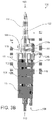
FIG. 3B illustrates a perspective section view of embodiments of a passive start drip chamber in an open configuration in accordance with aspects of the present disclosure. -
FIG. 4A illustrates a front section view of embodiments of a passive start drip chamber in an occluded configuration in accordance with aspects of the present disclosure. -
FIG. 4B illustrates a perspective section view of embodiments of a passive start drip chamber in an occluded configuration in accordance with aspects of the present disclosure. - In the following detailed description, specific details are set forth to provide an understanding of the subject technology. It will be apparent, however, to one ordinarily skilled in the art that the subject technology may be practiced without some of these specific details. In other instances, well-known structures and techniques have not been shown in detail so as not to obscure the subject technology.
- A phrase such as "an aspect" does not imply that such aspect is essential to the subject technology or that such aspect applies to all configurations of the subject technology. A disclosure relating to an aspect may apply to all configurations, or one or more configurations. An aspect may provide one or more examples of the disclosure. A phrase such as "an aspect" may refer to one or more aspects and vice versa. A phrase such as "an embodiment" does not imply that such embodiment is essential to the subject technology or that such embodiment applies to all configurations of the subject technology. A disclosure relating to an embodiment may apply to all embodiments, or one or more embodiments. An embodiment may provide one or more examples of the disclosure. A phrase such as "an embodiment" may refer to one or more embodiments and vice versa. A phrase such as "a configuration" does not imply that such configuration is essential to the subject technology or that such configuration applies to all configurations of the subject technology. A disclosure relating to a configuration may apply to all configurations, or one or more configurations. A configuration may provide one or more examples of the disclosure. A phrase such as "a configuration" may refer to one or more configurations and vice versa.
- The present disclosure relates to a passive start drip chamber for use in medical infusion therapy.
FIG. 1 illustrates embodiments of a passive startdrip chamber device 100 configured to control flow of a primary fluid source 908 andsecondary fluid source 906 to a patient (not shown). The passive startdrip chamber device 100 may be fluidly coupled to asecondary fluid source 906 and thefluid pathway 910 between a primary fluid source 908 and a patient. Upon coupling, flow from the primary fluid source 908 may be diverted to the passive startdrip chamber device 100. The passive startdrip chamber device 100 may then control flow of the primary fluid source 908 and thesecondary fluid source 906 to the patient. Referring toFIG. 2 , embodiments are illustrated having a plurality of passive startdrip chamber devices 100 andsecondary fluid sources 906 fluidly coupled to afluid pathway 910 between a primary fluid source 908 and a patient (not shown). - Referring to
FIGS. 3A-4B , the passive startdrip chamber device 100 comprises abody 102 forming achamber 104, two or more flow ports where fluid may enter thechamber 104 from a fluid source (e.g., an intravenous bag ("IV bag") or a line connected to an IV bag), and anoutput port 110 where fluid may exit thechamber 104. In some embodiments, thebody 102 comprises a port where a primary fluid 908 may enter the drip chamber, a port where asecondary fluid 906 may enter the drip chamber, and a port for fluid to exit 110 the drip chamber. Each 906/908 port is fluidly connected to thechamber 104 within thebody 102. In some embodiments, asecondary flow port 106 is disposed at a top of the body 102 (e.g., an end above or opposite the output port), while aprimary flow port 108 andoutput flow port 110 are disposed along thebody 102. Theprimary flow port 108 is fluidly coupled to aflow path 114 disposed through thebody 102 such that fluid from theprimary flow port 108 enters a top portion of thechamber 104. In some embodiments, the portion of thebody 102 comprising theflow path 114 extends as achannel 134 from the top portion of thechamber 104, and in some embodiments, the portion of thebody 102 comprising theflow path 114 extends as achannel 134 within an interior of thechamber 104 from the top portion of thechamber 104. Thesecondary flow port 106 is configured to couple with asecondary fluid source 906 such as a fluid bag. Thesecondary flow port 106 may be coupled with a fluid bag using a fluid fitting, including a luer-type fitting. In some embodiments, thesecondary flow port 106 comprises anintravenous bag spike 116 having a lumen extending therein to fluidly couple the chamber with a fluid bag. - Referring to
FIG. 4B , flow from two or more fluid sources to a patient is controlled within thebody 102. More specifically, flow of a primary fluid into thechamber 104 is reduced or halted as a secondary fluid enters thechamber 104. The flow of a primary fluid into thechamber 104 is stopped by the closing of a valve, fluid pathway, or fluid conduit within thechamber 104. Referring toFIG. 4B , as the flow of secondary fluid into thechamber 104 reduces or ceases, the fluid level within the chamber decreases, and the valve, fluid pathway, or fluid conduit opens and the primary fluid may once again flow into thechamber 104. By reducing or stopping flow of the primary fluid during flow of the secondary fluid, and then restarting flow of the primary fluid after flow of the secondary fluid has completed, complete and accurate delivery of the secondary fluid to the patient can be assured and provided with little or no subsequent adjustment by a caregiver. - The
body 102 may be composed of a malleable yet resilient material that allows the walls of thebody 102 to be flexible. For example, the walls may be sufficiently resilient to permit elastic deformation when the wall is collapsed to engage an opposing wall or structures within the chamber. In some embodiments, the walls of thebody 102 may be squeezed to expel air or other gasses from within thechamber 104. Air may be expelled into the secondary fluid source, or through avalve 128, such as a hydrophobic filter, to the atmosphere. Thebody 102 andchamber 104 may be any size that achieves the desired flow rate and volume. For example, thechamber 104 volume may be selected to achieve a specific flow rate or to retain a specific valve size. The wall thickness of thebody 102 may be selected to achieve a specific resiliency. - In some embodiments, the
body 102 may have one or more flow ports in alternate or additional locations on thebody 102. For example, theprimary flow port 108 may be coupled to thebody 102 parallel to thesecondary flow port 106. In some embodiments, thesecondary flow port 106 may be formed as acap 120 coupled to thebody 102 such that thecap 120 encloses the top portion of thechamber 104. In some embodiments, thecap 120 is removably coupled to the body, thereby providing access to thechamber 104. Thecap 120 can include anauxiliary flow path 122. Theauxiliary flow path 122 may be disposed through the cap, between thesecondary flow port 106 and anaccess plug 124a on an external surface of thecap 120. Thecap 120 may include anadditional access plug 124b, providing access to theflow path 114 of theprimary flow port 108. - In some embodiments, the valve includes a
float 112 disposed within thechamber 104 between thesecondary flow port 106 at the top of thechamber 104 and theoutput flow port 110 at the bottom of thechamber 104. Thefloat 112 may be any shape but is preferably shaped to fit within thechamber 104 and may be configured to move axially between the top and bottom of thechamber 104. - Referring to
FIG. 4B , thefloat 112 may be a cylinder having one or moreaxial grooves 130 on the outer surface, wherein the axial grooves are configured to mate with a rail, guide, orprotrusion 132 along a surface of thechamber 104. The mating of thegroove 130 andrail 132 allow the float to move axially within the chamber, yet prevent torsional rotation of the float. In some embodiments, thegrooves 130 may be on an internal surface of the chamber, and the rail, guide, orprotrusions 132 may be on the outer surface of thefloat 112. - The diameter of the
float 112 may be selected to assure stability within the chamber during movement, yet allow fluid to flow around thefloat 112. In some embodiments, thegrooves 130 or indentations provide a fluid flow path around thefloat 112. In some embodiments, thechamber 104 comprises an annular ring or seat such that theoutput port 110 becomes fluidly sealed when thefloat 112 is in a lowest position within the chamber, thereby preventing or reducing the likelihood of air from passing through thechamber 104 to the patient or to a pump. - The
float 112 may comprise specific buoyancy, causing it to raise or lower with a specific fluid level. Thefloat 112 may be solid or hollow, and may comprise air or foam. Preferably, thefloat 112 material will not degrade in the environment of thechamber 104. In some embodiments, the buoyancy of thefloat 112 is adjustable. For example, thefloat 112 may comprise a dial or selector to adjust buoyancy. - Referring to
FIGS. 4A-4B , a portion of thefloat 112 may include aprotrusion 118 that extends from thefloat 112 toward the top of the chamber. In some embodiments, the protrusion can extend in other directions, depending on the relative orientation of the float with respect to flow channels of the device. At least a portion of theprotrusion 118 extends into theflow path 114 of theprimary flow port 108 at the top of thedrip chamber 104. When thefloat 112 is at a lowest position adjacent to theoutput flow port 110, for example, when no flow from thesecondary flow port 106 is present, theprotrusion 118 partially extends into theflow path 114. In some embodiments, a portion of thecap 120 extends into thechamber 104, down from a top portion of the chamber, and comprises theflow path 114. The portion of thecap 120 that extends into thechamber 104 may further comprise achannel 134 that provides fluid communication between theflow path 114 and thechamber 104. Thechannel 134 may be disposed along theflow path 114 and through the portion of thecap 120 that extends into thechamber 104. - When the
protrusion 118 is only partially extended into thechannel 134, theaperture 126 allows fluid to flow through theprimary flow port 108, through theflow path 114 andchannel 134, and through theaperture 126 into thechamber 104. As flow from thesecondary flow port 106 enters thechamber 104, thefloat 112 rises in thedrip chamber 104. As thefloat 112 rises within thechamber 104, theprotrusion 118 advances along thechannel 134 thereby blocking flow through theaperture 126, occluding theflow path 114, and halting flow from theprimary flow port 108 into thechamber 104. Upon a reduction or cessation of flow from thesecondary flow port 106 into thechamber 104 thefloat 112 lowers, thereby retracting or withdrawing theprotrusion 118 along thechannel 134, exposing theaperture 126, and allowing flow from theprimary flow port 108 to enter thechamber 104 and ultimately exit from theoutput port 110. - In some embodiments, the
float 112 includes two ormore protrusions 118, whereby two or more flow ports into thechamber 104 may be controlled. For example, thefloat 112 may include twoprotrusions 118 having varying lengths. When thefloat 112 rises, thelonger protrusion 118 would occlude a first fluid flow port before the shorter protrusion occludes a second fluid flow port. In this example, flow from the second fluid flow port into thechamber 104 would continue until thefloat 112 rises to a level that causes theshorter protrusion 118 to also occlude the second fluid flow port. - In some embodiments, the
body 102 comprises two ormore chambers 104 and floats 112, allowing for two or more primary or secondary fluids to be coupled with the passive startdrip chamber device 100. In some embodiments, alower float 112 andupper float 112 are linearly disposed within thechamber 104, allowing for control of several fluid flows into thechamber 104. For example, thelower float 112 may have aprotrusion 118 that extends through and aperture in theupper float 112. Alternatively, theupper float 112 may have a surface indentation configured to allow theprotrusion 118 of thelower float 112 to move along side of theupper float 112. In some embodiments, afirst float 112 andsecond float 112 are disposed in parallel within thechamber 104. For example, eachfloat 112 may comprise aprotrusion 118 to control a flow port leading into thechamber 104. - The foregoing description is provided to enable a person skilled in the art to practice the various configurations described herein. While the subject technology has been particularly described with reference to the various figures and configurations, it should be understood that these are for illustration purposes only and should not be taken as limiting the scope of the subject technology.
- There may be many other ways to implement the subject technology. Various functions and elements described herein may be partitioned differently from those shown without departing from the scope of the subject technology. Various modifications to these configurations will be readily apparent to those skilled in the art, and generic principles defined herein may be applied to other configurations. Thus, many changes and modifications may be made to the subject technology, by one having ordinary skill in the art, without departing from the scope of the subject technology.
- As used herein, the phrase "at least one of" preceding a series of items, with the term "and" or "or" to separate any of the items, modifies the list as a whole, rather than each member of the list (i.e., each item). The phrase "at least one of" does not require selection of at least one of each item listed; rather, the phrase allows a meaning that includes at least one of any one of the items, and/or at least one of any combination of the items, and/or at least one of each of the items. By way of example, the phrases "at least one of A, B, and C" or "at least one of A, B, or C" each refer to only A, only B, or only C; any combination of A, B, and C; and/or at least one of each of A, B, and C.
- Furthermore, to the extent that the term "include," "have," or the like is used in the description or the claims, such term is intended to be inclusive in a manner similar to the term "comprise" as "comprise" is interpreted when employed as a transitional word in a claim. The word "exemplary" is used herein to mean "serving as an example, instance, or illustration." Any embodiment described herein as "exemplary" is not necessarily to be construed as preferred or advantageous over other embodiments.
- A reference to an element in the singular is not intended to mean "one and only one" unless specifically stated, but rather "one or more." The term "some" refers to one or more. All structural and functional equivalents to the elements of the various configurations described throughout this disclosure that are known or later come to be known to those of ordinary skill in the art are expressly incorporated herein by reference and intended to be encompassed by the subject technology. Moreover, nothing disclosed herein is intended to be dedicated to the public regardless of whether such disclosure is explicitly recited in the above description.
- While certain aspects and embodiments of the subject technology have been described, these have been presented by way of example only, and are not intended to limit the scope of the subject technology. Indeed, the novel methods and systems described herein may be embodied in a variety of other forms without departing from the spirit thereof. The accompanying claims and their equivalents are intended to cover such forms or modifications as would fall within the scope and spirit of the subject technology.
- Described herein are at least the following concepts:
-
Concept 1. A passive start drip chamber device comprising:- a chamber fluidly coupled to first and second input flow ports and an output flow port;
- a float disposed within the chamber, the float configured to move between an occluding configuration, wherein the first input flow port is occluded, and an open configuration, wherein the first input flow port is not occluded, based on a level of fluid within the chamber.
- Concept 2. The device of
concept 1, wherein the float comprises an elongate member that occludes the first input flow port when the float is in the occluding configuration. - Concept 3. The device of concept 2, wherein the elongate member resides within a flow path channel of the first input flow port, and axial movement of the float within the chamber translates to axial movement of the elongate member along the flow path channel.
- Concept 4. The device of
concept 1, wherein the float is configured to move from the occluding configuration toward the open configuration when fluid flow through the second input flow port reduces such that the level of fluid within the chamber drops below a filled threshold. - Concept 5. The device of
concept 1, wherein the float is configured to move from the open configuration toward the occluding configuration when the level of fluid within the chamber exceeds a drained threshold. - Concept 6. The device of
concept 1, wherein the first input flow port comprises a channel configured to conduct fluid to the chamber, and the float comprises an occluding portion disposed within the channel that moves along the channel and occludes or opens the port when the float is in the respective occluding or open configurations. - Concept 7. The device of
concept 1, wherein at least a portion of a wall of the chamber is sufficiently resilient to permit elastic deformation when the wall is collapsed to engage an opposing wall or structures within the chamber. - Concept 8. The device of
concept 1, wherein the second input port comprises a fluid connector configured to fluidly couple with a fluid source. - Concept 9. The device of concept 8, wherein the fluid connector comprises an intravenous bag spike having a lumen extending therein to conduct fluid.
- Concept 10. The device of
concept 1, further comprising a valve fluidly coupled to the chamber, the valve configured to release a gas from within the chamber. - Concept 11. The device of
concept 1, wherein a top of the chamber, opposite the output flow port, comprises a removable cap. -
Concept 12. The chamber of concept 11, wherein the removable cap comprises at least one of the first or second input flow ports. - Concept 13. The device of
concept 1, wherein each of the float and the chamber comprise either an axial groove or a corresponding protrusion, the groove and protrusion configured to matingly align the float within the chamber. - Concept 14. The device of
concept 1, wherein the float is configured to occlude the output flow port when the level of fluid within the chamber drops below a drained threshold. - Concept 15. A passive start drip chamber device comprising:
- a body with an interior chamber, the body having a first input flow port, a second input flow port, and an output flow port, the first input flow port comprises an opening fluidly coupled with the interior chamber;
- a float within the interior chamber, the float comprising a portion configured to extend into the opening;
- wherein the float is configured to rise and fall in the chamber based on a fluid level within the chamber, such that the portion moves relative to the opening between a closed configuration, wherein fluid through the first input flow port is occluded by the portion, and an open configuration, wherein the portion is withdrawn from the opening such that fluid is conducted through the opening and into to the chamber.
- Concept 16. The device of concept 15, further comprising a channel fluidly coupled to the opening, wherein the float portion is configured to extend along and move within the channel.
- Concept 17. The device of concept 15, wherein at least a portion of the chamber wall is sufficiently resilient to permit elastic deformation when the wall is collapsed to engage an opposing wall or structures within the chamber. Concept 18. The device of concept 15, further comprising a valve coupled to the chamber, the valve configured to release a gas from within the chamber.
- Concept 19. The device of concept 15, wherein a top portion of the chamber, opposite the output flow port, comprises a removable cap.
- Concept 20. The device of concept 19, wherein the removable cap comprises at least one of the first or second input flow ports.
Claims (15)
- A passive start drip chamber device comprising:- a body (102) comprising a chamber (104) formed between a top portion and a bottom portion of the body, the chamber fluidly coupled to a primary flow port (108) for entry of a first fluid into the chamber, a secondary flow port (106) for entry of a second fluid into the chamber, and an output flow port (110) to permit any of the first and second fluid to exit the chamber; and- a primary flow path (114) coupled to the primary flow port (108) and disposed through the body from the bottom portion of the body to a top portion of the body such that the first fluid moves through the primary flow path and enters the chamber through the top portion of the body; and- a float valve (112) disposed within the chamber and configured to move, based on a level of fluid within the chamber, between an occluding configuration, wherein the primary flow path is occluded, and an open configuration, wherein the primary flow path is not occluded.
- The passive start drip chamber device of Claim 1, wherein the float valve comprises an elongate member that occludes the primary flow port when the float valve is in the occluding configuration.
- The passive start drip chamber device of Claim 2, wherein the elongate member resides within a flow path channel of the primary flow port, and axial movement of the float valve within the chamber translates to axial movement of the elongate member along the flow path channel.
- The passive start drip chamber device of Claim 3, wherein the elongate member occludes the flow path channel when the float valve is in the occluding configuration.
- The passive start drip chamber device of Claim 3, wherein the flow path channel extends through the top portion of the body into the chamber, and wherein the primary flow path extends through the channel.
- The passive start drip chamber device of Claim 1, wherein the float valve is configured to move from the open configuration toward the occluding configuration when the level of liquid within the chamber exceeds a drained threshold.
- The passive start drip chamber device of Claim 1, wherein at least a portion of a wall of the chamber is sufficiently resilient to permit elastic deformation when the wall is collapsed to engage an opposing wall or structures within the chamber.
- The passive start drip chamber device of Claim 1, wherein each of the float valve and the chamber comprise either an axial groove or a corresponding protrusion, the groove and protrusion configured to matingly align the float valve within the chamber.
- The passive start drip chamber device of Claim 1, wherein the float valve comprises a groove that extends along an outer surface of the float valve, the groove configured to permit a fluid to move through the chamber, between the top and bottom portion of the body.
- The passive start drip chamber device of Claim 1, wherein the secondary flow port comprises an intravenous bag spike having a lumen extending therein to conduct fluid.
- The passive start drip chamber device of Claim 1, further comprising a valve fluidly coupled to the chamber, the valve configured to release a gas from within the chamber.
- The passive start drip chamber device of Claim 1, wherein a top of the chamber, opposite the output flow port, comprises a removable cap.
- The passive start drip chamber device of Claim 1, wherein, in the occluding configuration, the level of liquid within the chamber is at a first level, and in the open configuration, the level of liquid within the chamber is at a second level, less than the first level.
- The passive start drip chamber device of Claim 1, wherein, in the occluding configuration, the float valve resists entry of fluid from the primary flow port into the chamber, and in the open configuration, the float valve permits entry of fluid from the primary and secondary flow port into the chamber.
- The passive start drip chamber device of any one of Claims 1 to 14, wherein the first fluid is a liquid and/or the second fluid is a liquid.
Applications Claiming Priority (3)
| Application Number | Priority Date | Filing Date | Title |
|---|---|---|---|
| US14/319,576 US9731070B2 (en) | 2014-06-30 | 2014-06-30 | Passive start drip chamber |
| PCT/US2015/036288 WO2016003653A1 (en) | 2014-06-30 | 2015-06-17 | Drip chamber with multiple ports for fluid input |
| EP15741634.8A EP3160543B1 (en) | 2014-06-30 | 2015-06-17 | Drip chamber with multiple ports for fluid input |
Related Parent Applications (2)
| Application Number | Title | Priority Date | Filing Date |
|---|---|---|---|
| EP15741634.8A Division EP3160543B1 (en) | 2014-06-30 | 2015-06-17 | Drip chamber with multiple ports for fluid input |
| EP15741634.8A Division-Into EP3160543B1 (en) | 2014-06-30 | 2015-06-17 | Drip chamber with multiple ports for fluid input |
Publications (2)
| Publication Number | Publication Date |
|---|---|
| EP3375469A1 true EP3375469A1 (en) | 2018-09-19 |
| EP3375469B1 EP3375469B1 (en) | 2019-11-13 |
Family
ID=53719912
Family Applications (2)
| Application Number | Title | Priority Date | Filing Date |
|---|---|---|---|
| EP15741634.8A Active EP3160543B1 (en) | 2014-06-30 | 2015-06-17 | Drip chamber with multiple ports for fluid input |
| EP18165223.1A Active EP3375469B1 (en) | 2014-06-30 | 2015-06-17 | Drip chamber with float valve for sequential fluid delivery |
Family Applications Before (1)
| Application Number | Title | Priority Date | Filing Date |
|---|---|---|---|
| EP15741634.8A Active EP3160543B1 (en) | 2014-06-30 | 2015-06-17 | Drip chamber with multiple ports for fluid input |
Country Status (10)
| Country | Link |
|---|---|
| US (3) | US9731070B2 (en) |
| EP (2) | EP3160543B1 (en) |
| JP (2) | JP6767884B2 (en) |
| CN (2) | CN106470715B (en) |
| AU (2) | AU2015284633B2 (en) |
| BR (1) | BR112016030466B1 (en) |
| CA (1) | CA2953111C (en) |
| ES (1) | ES2684668T3 (en) |
| MX (2) | MX377990B (en) |
| WO (1) | WO2016003653A1 (en) |
Families Citing this family (13)
| Publication number | Priority date | Publication date | Assignee | Title |
|---|---|---|---|---|
| US9731070B2 (en) * | 2014-06-30 | 2017-08-15 | Carefusion 303, Inc. | Passive start drip chamber |
| US10413662B2 (en) | 2015-05-14 | 2019-09-17 | Carefusion 303, Inc. | Priming apparatus and method |
| US11446196B2 (en) | 2018-03-26 | 2022-09-20 | Augustine Biomedical + Design, LLC | Relocation module and methods for surgical equipment |
| US11432982B2 (en) | 2018-03-26 | 2022-09-06 | Augustine Biomedical + Design, LLC | Relocation module and methods for surgical equipment |
| US11160710B1 (en) | 2020-05-20 | 2021-11-02 | Augustine Biomedical + Design, LLC | Relocation module and methods for surgical equipment |
| US11291602B2 (en) | 2018-03-26 | 2022-04-05 | Augustine Biomedical + Design, LLC | Relocation module and methods for surgical equipment |
| US11219570B2 (en) | 2018-03-26 | 2022-01-11 | Augustine Biomedical + Design, LLC | Relocation module and methods for surgical equipment |
| US10507153B2 (en) | 2018-03-26 | 2019-12-17 | Augustine Biomedical + Design, LLC | Relocation modules and methods for surgical field |
| US11426318B2 (en) | 2020-05-20 | 2022-08-30 | Augustine Biomedical + Design, LLC | Medical module including automated dose-response record system |
| DE102019215022A1 (en) * | 2019-09-30 | 2021-04-01 | B. Braun Melsungen Aktiengesellschaft | Drip chamber arrangement for a medical infusion system |
| WO2021236077A1 (en) * | 2020-05-20 | 2021-11-25 | Augustine Biomedical + Design, LLC | Relocation module and methods for surgical equipment |
| US20220080107A1 (en) * | 2020-09-11 | 2022-03-17 | Carefusion 303. Inc. | Drip chamber assembly |
| CN113521444B (en) * | 2021-07-15 | 2022-06-21 | 陕西省人民医院 | A continuous infusion set with acupuncture-type sequential switching channels |
Citations (5)
| Publication number | Priority date | Publication date | Assignee | Title |
|---|---|---|---|---|
| US4256103A (en) * | 1978-10-11 | 1981-03-17 | James Paxinos | Automatic sequential fluid flow apparatus |
| US6213986B1 (en) * | 1995-09-29 | 2001-04-10 | Appro Healthcare, Inc. | Liquid flow rate control device |
| US20070215637A1 (en) * | 2004-05-03 | 2007-09-20 | Yong-Nyun Kim | Device for regulating flow rate |
| US20110275988A1 (en) * | 2010-05-06 | 2011-11-10 | Becton, Dickinson And Company | Systems and methods for providing a closed venting hazardous drug iv set |
| US20130331811A1 (en) * | 2012-06-12 | 2013-12-12 | Carefusion 303, Inc. | Drip chamber |
Family Cites Families (21)
| Publication number | Priority date | Publication date | Assignee | Title |
|---|---|---|---|---|
| US2784733A (en) * | 1954-10-08 | 1957-03-12 | Baxter Don Inc | Check valve for parenteral solutions |
| US4005710A (en) | 1975-02-12 | 1977-02-01 | Abbott Laboratories | Parenteral apparatus with one-way valve |
| JPS5335511A (en) | 1976-09-13 | 1978-04-03 | Sony Corp | Recorder-reproducer for picture signal |
| US4186740A (en) * | 1978-02-06 | 1980-02-05 | Guerra Romeo E | Method and apparatus for regulating intravenous flow of a liquid |
| JPS571951Y2 (en) * | 1978-03-22 | 1982-01-13 | ||
| US4449976A (en) * | 1981-05-21 | 1984-05-22 | Baxter Travenol Laboratories, Inc. | Device for preserving continuity of intravenous flow |
| US4563173A (en) * | 1983-04-19 | 1986-01-07 | National Biomedical Research Foundation | Pump-actuated sequencing valve and system |
| JPH07148256A (en) * | 1993-11-30 | 1995-06-13 | Yasuhiro Mizuno | Valve device |
| CN2201947Y (en) | 1994-06-13 | 1995-06-28 | 彭元济 | Automatic-closing medical transfusion system |
| AU723789B2 (en) | 1995-09-29 | 2000-09-07 | Phillip H. Darling Jr. | Liquid flow rate control device |
| US5839466A (en) | 1996-04-29 | 1998-11-24 | Dutter; Marshall | Automatic watering device |
| US6485454B1 (en) | 2000-10-13 | 2002-11-26 | Edward Yang | Automatic infusion set for continuously infusing liquid medicine of double bottles |
| US7722577B2 (en) * | 2005-02-18 | 2010-05-25 | Becton, Dickinson And Company | Bubble free—self primed IV set |
| CN2721106Y (en) * | 2004-02-25 | 2005-08-31 | 梁海东 | Multifunctional infusion apparatus |
| US9352080B2 (en) | 2005-10-13 | 2016-05-31 | Analytica Limited | Burette |
| US7865979B2 (en) | 2007-07-10 | 2011-01-11 | Hand Douglas P | Flush valve structure for a toilet tank |
| US9205248B2 (en) | 2010-02-24 | 2015-12-08 | Becton, Dickinson And Company | Safety Drug delivery connectors |
| CN102727957B (en) | 2012-06-06 | 2014-05-14 | 唐敏峰 | Multi-bottle automatic continuous penetrating venous infusion apparatus |
| CN102743809A (en) | 2012-07-14 | 2012-10-24 | 汤园园 | Intermittent transfusion set |
| CN102973997B (en) | 2012-12-28 | 2014-04-30 | 唐敏峰 | Multifunctional venous infusion apparatus |
| US9731070B2 (en) * | 2014-06-30 | 2017-08-15 | Carefusion 303, Inc. | Passive start drip chamber |
-
2014
- 2014-06-30 US US14/319,576 patent/US9731070B2/en active Active
-
2015
- 2015-06-17 ES ES15741634.8T patent/ES2684668T3/en active Active
- 2015-06-17 CA CA2953111A patent/CA2953111C/en active Active
- 2015-06-17 BR BR112016030466-7A patent/BR112016030466B1/en active IP Right Grant
- 2015-06-17 EP EP15741634.8A patent/EP3160543B1/en active Active
- 2015-06-17 MX MX2016017043A patent/MX377990B/en unknown
- 2015-06-17 AU AU2015284633A patent/AU2015284633B2/en active Active
- 2015-06-17 JP JP2016575751A patent/JP6767884B2/en active Active
- 2015-06-17 CN CN201580035501.6A patent/CN106470715B/en active Active
- 2015-06-17 EP EP18165223.1A patent/EP3375469B1/en active Active
- 2015-06-17 WO PCT/US2015/036288 patent/WO2016003653A1/en not_active Ceased
- 2015-06-17 CN CN202010105631.5A patent/CN111282077B/en active Active
-
2016
- 2016-12-19 MX MX2020013111A patent/MX2020013111A/en unknown
-
2017
- 2017-08-09 US US15/672,917 patent/US10653832B2/en active Active
-
2019
- 2019-08-26 AU AU2019222780A patent/AU2019222780B2/en active Active
-
2020
- 2020-05-18 US US16/877,312 patent/US11439751B2/en active Active
- 2020-09-18 JP JP2020157133A patent/JP6990283B2/en active Active
Patent Citations (5)
| Publication number | Priority date | Publication date | Assignee | Title |
|---|---|---|---|---|
| US4256103A (en) * | 1978-10-11 | 1981-03-17 | James Paxinos | Automatic sequential fluid flow apparatus |
| US6213986B1 (en) * | 1995-09-29 | 2001-04-10 | Appro Healthcare, Inc. | Liquid flow rate control device |
| US20070215637A1 (en) * | 2004-05-03 | 2007-09-20 | Yong-Nyun Kim | Device for regulating flow rate |
| US20110275988A1 (en) * | 2010-05-06 | 2011-11-10 | Becton, Dickinson And Company | Systems and methods for providing a closed venting hazardous drug iv set |
| US20130331811A1 (en) * | 2012-06-12 | 2013-12-12 | Carefusion 303, Inc. | Drip chamber |
Also Published As
| Publication number | Publication date |
|---|---|
| JP6767884B2 (en) | 2020-10-14 |
| MX377990B (en) | 2025-03-10 |
| EP3160543B1 (en) | 2018-05-23 |
| AU2019222780A1 (en) | 2019-09-12 |
| AU2015284633A1 (en) | 2017-01-12 |
| BR112016030466A2 (en) | 2017-08-22 |
| JP6990283B2 (en) | 2022-01-12 |
| MX2016017043A (en) | 2017-07-28 |
| EP3375469B1 (en) | 2019-11-13 |
| US20150374909A1 (en) | 2015-12-31 |
| BR112016030466B1 (en) | 2022-04-05 |
| AU2019222780B2 (en) | 2020-08-27 |
| EP3160543A1 (en) | 2017-05-03 |
| CN106470715A (en) | 2017-03-01 |
| WO2016003653A1 (en) | 2016-01-07 |
| CA2953111A1 (en) | 2016-01-07 |
| CN111282077A (en) | 2020-06-16 |
| US10653832B2 (en) | 2020-05-19 |
| JP2017520322A (en) | 2017-07-27 |
| US20170333626A1 (en) | 2017-11-23 |
| CA2953111C (en) | 2023-08-08 |
| US11439751B2 (en) | 2022-09-13 |
| MX2020013111A (en) | 2021-02-18 |
| JP2020199335A (en) | 2020-12-17 |
| US20200397986A1 (en) | 2020-12-24 |
| CN111282077B (en) | 2022-04-22 |
| US9731070B2 (en) | 2017-08-15 |
| ES2684668T3 (en) | 2018-10-04 |
| AU2015284633B2 (en) | 2019-06-20 |
| CN106470715B (en) | 2020-03-17 |
Similar Documents
| Publication | Publication Date | Title |
|---|---|---|
| US11439751B2 (en) | Passive start drip chamber | |
| US20220339354A1 (en) | Passive restart y-site | |
| CN104888310A (en) | Blood return prevention infusion connector | |
| JP4253538B2 (en) | CHEMICAL LIQUID INTRODUCING DEVICE, CHEMICAL SOLUTION INJECTION DEVICE EQUIPPED WITH THE SAME, AND INTERMEDIATE ADMINISTRATION SYSTEM |
Legal Events
| Date | Code | Title | Description |
|---|---|---|---|
| PUAI | Public reference made under article 153(3) epc to a published international application that has entered the european phase |
Free format text: ORIGINAL CODE: 0009012 |
|
| STAA | Information on the status of an ep patent application or granted ep patent |
Free format text: STATUS: THE APPLICATION HAS BEEN PUBLISHED |
|
| AC | Divisional application: reference to earlier application |
Ref document number: 3160543 Country of ref document: EP Kind code of ref document: P |
|
| AK | Designated contracting states |
Kind code of ref document: A1 Designated state(s): AL AT BE BG CH CY CZ DE DK EE ES FI FR GB GR HR HU IE IS IT LI LT LU LV MC MK MT NL NO PL PT RO RS SE SI SK SM TR |
|
| STAA | Information on the status of an ep patent application or granted ep patent |
Free format text: STATUS: REQUEST FOR EXAMINATION WAS MADE |
|
| 17P | Request for examination filed |
Effective date: 20190313 |
|
| RBV | Designated contracting states (corrected) |
Designated state(s): AL AT BE BG CH CY CZ DE DK EE ES FI FR GB GR HR HU IE IS IT LI LT LU LV MC MK MT NL NO PL PT RO RS SE SI SK SM TR |
|
| GRAP | Despatch of communication of intention to grant a patent |
Free format text: ORIGINAL CODE: EPIDOSNIGR1 |
|
| STAA | Information on the status of an ep patent application or granted ep patent |
Free format text: STATUS: GRANT OF PATENT IS INTENDED |
|
| RIC1 | Information provided on ipc code assigned before grant |
Ipc: A61M 5/40 20060101ALI20190517BHEP Ipc: A61M 39/22 20060101ALN20190517BHEP Ipc: A61M 5/14 20060101AFI20190517BHEP |
|
| INTG | Intention to grant announced |
Effective date: 20190604 |
|
| GRAS | Grant fee paid |
Free format text: ORIGINAL CODE: EPIDOSNIGR3 |
|
| GRAA | (expected) grant |
Free format text: ORIGINAL CODE: 0009210 |
|
| STAA | Information on the status of an ep patent application or granted ep patent |
Free format text: STATUS: THE PATENT HAS BEEN GRANTED |
|
| AC | Divisional application: reference to earlier application |
Ref document number: 3160543 Country of ref document: EP Kind code of ref document: P |
|
| AK | Designated contracting states |
Kind code of ref document: B1 Designated state(s): AL AT BE BG CH CY CZ DE DK EE ES FI FR GB GR HR HU IE IS IT LI LT LU LV MC MK MT NL NO PL PT RO RS SE SI SK SM TR |
|
| REG | Reference to a national code |
Ref country code: CH Ref legal event code: EP Ref country code: AT Ref legal event code: REF Ref document number: 1201015 Country of ref document: AT Kind code of ref document: T Effective date: 20191115 |
|
| REG | Reference to a national code |
Ref country code: DE Ref legal event code: R096 Ref document number: 602015041874 Country of ref document: DE |
|
| REG | Reference to a national code |
Ref country code: IE Ref legal event code: FG4D |
|
| REG | Reference to a national code |
Ref country code: NL Ref legal event code: MP Effective date: 20191113 |
|
| REG | Reference to a national code |
Ref country code: LT Ref legal event code: MG4D |
|
| PG25 | Lapsed in a contracting state [announced via postgrant information from national office to epo] |
Ref country code: SE Free format text: LAPSE BECAUSE OF FAILURE TO SUBMIT A TRANSLATION OF THE DESCRIPTION OR TO PAY THE FEE WITHIN THE PRESCRIBED TIME-LIMIT Effective date: 20191113 Ref country code: LV Free format text: LAPSE BECAUSE OF FAILURE TO SUBMIT A TRANSLATION OF THE DESCRIPTION OR TO PAY THE FEE WITHIN THE PRESCRIBED TIME-LIMIT Effective date: 20191113 Ref country code: NL Free format text: LAPSE BECAUSE OF FAILURE TO SUBMIT A TRANSLATION OF THE DESCRIPTION OR TO PAY THE FEE WITHIN THE PRESCRIBED TIME-LIMIT Effective date: 20191113 Ref country code: BG Free format text: LAPSE BECAUSE OF FAILURE TO SUBMIT A TRANSLATION OF THE DESCRIPTION OR TO PAY THE FEE WITHIN THE PRESCRIBED TIME-LIMIT Effective date: 20200213 Ref country code: FI Free format text: LAPSE BECAUSE OF FAILURE TO SUBMIT A TRANSLATION OF THE DESCRIPTION OR TO PAY THE FEE WITHIN THE PRESCRIBED TIME-LIMIT Effective date: 20191113 Ref country code: LT Free format text: LAPSE BECAUSE OF FAILURE TO SUBMIT A TRANSLATION OF THE DESCRIPTION OR TO PAY THE FEE WITHIN THE PRESCRIBED TIME-LIMIT Effective date: 20191113 Ref country code: PL Free format text: LAPSE BECAUSE OF FAILURE TO SUBMIT A TRANSLATION OF THE DESCRIPTION OR TO PAY THE FEE WITHIN THE PRESCRIBED TIME-LIMIT Effective date: 20191113 Ref country code: PT Free format text: LAPSE BECAUSE OF FAILURE TO SUBMIT A TRANSLATION OF THE DESCRIPTION OR TO PAY THE FEE WITHIN THE PRESCRIBED TIME-LIMIT Effective date: 20200313 Ref country code: GR Free format text: LAPSE BECAUSE OF FAILURE TO SUBMIT A TRANSLATION OF THE DESCRIPTION OR TO PAY THE FEE WITHIN THE PRESCRIBED TIME-LIMIT Effective date: 20200214 Ref country code: NO Free format text: LAPSE BECAUSE OF FAILURE TO SUBMIT A TRANSLATION OF THE DESCRIPTION OR TO PAY THE FEE WITHIN THE PRESCRIBED TIME-LIMIT Effective date: 20200213 |
|
| PG25 | Lapsed in a contracting state [announced via postgrant information from national office to epo] |
Ref country code: RS Free format text: LAPSE BECAUSE OF FAILURE TO SUBMIT A TRANSLATION OF THE DESCRIPTION OR TO PAY THE FEE WITHIN THE PRESCRIBED TIME-LIMIT Effective date: 20191113 Ref country code: HR Free format text: LAPSE BECAUSE OF FAILURE TO SUBMIT A TRANSLATION OF THE DESCRIPTION OR TO PAY THE FEE WITHIN THE PRESCRIBED TIME-LIMIT Effective date: 20191113 Ref country code: IS Free format text: LAPSE BECAUSE OF FAILURE TO SUBMIT A TRANSLATION OF THE DESCRIPTION OR TO PAY THE FEE WITHIN THE PRESCRIBED TIME-LIMIT Effective date: 20200313 |
|
| PG25 | Lapsed in a contracting state [announced via postgrant information from national office to epo] |
Ref country code: AL Free format text: LAPSE BECAUSE OF FAILURE TO SUBMIT A TRANSLATION OF THE DESCRIPTION OR TO PAY THE FEE WITHIN THE PRESCRIBED TIME-LIMIT Effective date: 20191113 |
|
| PG25 | Lapsed in a contracting state [announced via postgrant information from national office to epo] |
Ref country code: RO Free format text: LAPSE BECAUSE OF FAILURE TO SUBMIT A TRANSLATION OF THE DESCRIPTION OR TO PAY THE FEE WITHIN THE PRESCRIBED TIME-LIMIT Effective date: 20191113 Ref country code: CZ Free format text: LAPSE BECAUSE OF FAILURE TO SUBMIT A TRANSLATION OF THE DESCRIPTION OR TO PAY THE FEE WITHIN THE PRESCRIBED TIME-LIMIT Effective date: 20191113 Ref country code: ES Free format text: LAPSE BECAUSE OF FAILURE TO SUBMIT A TRANSLATION OF THE DESCRIPTION OR TO PAY THE FEE WITHIN THE PRESCRIBED TIME-LIMIT Effective date: 20191113 Ref country code: EE Free format text: LAPSE BECAUSE OF FAILURE TO SUBMIT A TRANSLATION OF THE DESCRIPTION OR TO PAY THE FEE WITHIN THE PRESCRIBED TIME-LIMIT Effective date: 20191113 Ref country code: DK Free format text: LAPSE BECAUSE OF FAILURE TO SUBMIT A TRANSLATION OF THE DESCRIPTION OR TO PAY THE FEE WITHIN THE PRESCRIBED TIME-LIMIT Effective date: 20191113 |
|
| REG | Reference to a national code |
Ref country code: DE Ref legal event code: R097 Ref document number: 602015041874 Country of ref document: DE |
|
| REG | Reference to a national code |
Ref country code: AT Ref legal event code: MK05 Ref document number: 1201015 Country of ref document: AT Kind code of ref document: T Effective date: 20191113 |
|
| PG25 | Lapsed in a contracting state [announced via postgrant information from national office to epo] |
Ref country code: SK Free format text: LAPSE BECAUSE OF FAILURE TO SUBMIT A TRANSLATION OF THE DESCRIPTION OR TO PAY THE FEE WITHIN THE PRESCRIBED TIME-LIMIT Effective date: 20191113 Ref country code: SM Free format text: LAPSE BECAUSE OF FAILURE TO SUBMIT A TRANSLATION OF THE DESCRIPTION OR TO PAY THE FEE WITHIN THE PRESCRIBED TIME-LIMIT Effective date: 20191113 |
|
| PLBE | No opposition filed within time limit |
Free format text: ORIGINAL CODE: 0009261 |
|
| STAA | Information on the status of an ep patent application or granted ep patent |
Free format text: STATUS: NO OPPOSITION FILED WITHIN TIME LIMIT |
|
| 26N | No opposition filed |
Effective date: 20200814 |
|
| PG25 | Lapsed in a contracting state [announced via postgrant information from national office to epo] |
Ref country code: AT Free format text: LAPSE BECAUSE OF FAILURE TO SUBMIT A TRANSLATION OF THE DESCRIPTION OR TO PAY THE FEE WITHIN THE PRESCRIBED TIME-LIMIT Effective date: 20191113 Ref country code: SI Free format text: LAPSE BECAUSE OF FAILURE TO SUBMIT A TRANSLATION OF THE DESCRIPTION OR TO PAY THE FEE WITHIN THE PRESCRIBED TIME-LIMIT Effective date: 20191113 |
|
| PG25 | Lapsed in a contracting state [announced via postgrant information from national office to epo] |
Ref country code: IT Free format text: LAPSE BECAUSE OF FAILURE TO SUBMIT A TRANSLATION OF THE DESCRIPTION OR TO PAY THE FEE WITHIN THE PRESCRIBED TIME-LIMIT Effective date: 20191113 Ref country code: MC Free format text: LAPSE BECAUSE OF FAILURE TO SUBMIT A TRANSLATION OF THE DESCRIPTION OR TO PAY THE FEE WITHIN THE PRESCRIBED TIME-LIMIT Effective date: 20191113 |
|
| REG | Reference to a national code |
Ref country code: CH Ref legal event code: PL |
|
| PG25 | Lapsed in a contracting state [announced via postgrant information from national office to epo] |
Ref country code: LU Free format text: LAPSE BECAUSE OF NON-PAYMENT OF DUE FEES Effective date: 20200617 |
|
| PG25 | Lapsed in a contracting state [announced via postgrant information from national office to epo] |
Ref country code: IE Free format text: LAPSE BECAUSE OF NON-PAYMENT OF DUE FEES Effective date: 20200617 Ref country code: LI Free format text: LAPSE BECAUSE OF NON-PAYMENT OF DUE FEES Effective date: 20200630 Ref country code: CH Free format text: LAPSE BECAUSE OF NON-PAYMENT OF DUE FEES Effective date: 20200630 |
|
| PG25 | Lapsed in a contracting state [announced via postgrant information from national office to epo] |
Ref country code: TR Free format text: LAPSE BECAUSE OF FAILURE TO SUBMIT A TRANSLATION OF THE DESCRIPTION OR TO PAY THE FEE WITHIN THE PRESCRIBED TIME-LIMIT Effective date: 20191113 Ref country code: MT Free format text: LAPSE BECAUSE OF FAILURE TO SUBMIT A TRANSLATION OF THE DESCRIPTION OR TO PAY THE FEE WITHIN THE PRESCRIBED TIME-LIMIT Effective date: 20191113 Ref country code: CY Free format text: LAPSE BECAUSE OF FAILURE TO SUBMIT A TRANSLATION OF THE DESCRIPTION OR TO PAY THE FEE WITHIN THE PRESCRIBED TIME-LIMIT Effective date: 20191113 |
|
| PG25 | Lapsed in a contracting state [announced via postgrant information from national office to epo] |
Ref country code: MK Free format text: LAPSE BECAUSE OF FAILURE TO SUBMIT A TRANSLATION OF THE DESCRIPTION OR TO PAY THE FEE WITHIN THE PRESCRIBED TIME-LIMIT Effective date: 20191113 |
|
| PGFP | Annual fee paid to national office [announced via postgrant information from national office to epo] |
Ref country code: DE Payment date: 20250520 Year of fee payment: 11 |
|
| PGFP | Annual fee paid to national office [announced via postgrant information from national office to epo] |
Ref country code: GB Payment date: 20250520 Year of fee payment: 11 |
|
| PGFP | Annual fee paid to national office [announced via postgrant information from national office to epo] |
Ref country code: BE Payment date: 20250520 Year of fee payment: 11 |
|
| PGFP | Annual fee paid to national office [announced via postgrant information from national office to epo] |
Ref country code: FR Payment date: 20250520 Year of fee payment: 11 |