EP3375317B1 - Fastener stringer, method for manufacturing same, and slide fastener - Google Patents
Fastener stringer, method for manufacturing same, and slide fastener Download PDFInfo
- Publication number
- EP3375317B1 EP3375317B1 EP15908297.3A EP15908297A EP3375317B1 EP 3375317 B1 EP3375317 B1 EP 3375317B1 EP 15908297 A EP15908297 A EP 15908297A EP 3375317 B1 EP3375317 B1 EP 3375317B1
- Authority
- EP
- European Patent Office
- Prior art keywords
- fastener
- layer
- resin layer
- surface resin
- metal
- Prior art date
- Legal status (The legal status is an assumption and is not a legal conclusion. Google has not performed a legal analysis and makes no representation as to the accuracy of the status listed.)
- Active
Links
- 238000004519 manufacturing process Methods 0.000 title claims description 11
- 238000000034 method Methods 0.000 title claims description 5
- 229910052751 metal Inorganic materials 0.000 claims description 168
- 239000002184 metal Substances 0.000 claims description 166
- 229920005989 resin Polymers 0.000 claims description 119
- 239000011347 resin Substances 0.000 claims description 119
- 229910006414 SnNi Inorganic materials 0.000 claims description 18
- 239000000463 material Substances 0.000 claims description 13
- 229910008336 SnCo Inorganic materials 0.000 claims description 8
- 239000010410 layer Substances 0.000 description 234
- PXHVJJICTQNCMI-UHFFFAOYSA-N nickel Substances [Ni] PXHVJJICTQNCMI-UHFFFAOYSA-N 0.000 description 18
- 238000007747 plating Methods 0.000 description 17
- 229910045601 alloy Inorganic materials 0.000 description 15
- 239000000956 alloy Substances 0.000 description 15
- 229910001369 Brass Inorganic materials 0.000 description 12
- 239000010951 brass Substances 0.000 description 12
- 238000005520 cutting process Methods 0.000 description 12
- 230000000052 comparative effect Effects 0.000 description 11
- 239000000843 powder Substances 0.000 description 10
- 239000010931 gold Substances 0.000 description 8
- 239000011248 coating agent Substances 0.000 description 7
- 238000000576 coating method Methods 0.000 description 7
- 239000003086 colorant Substances 0.000 description 6
- 229920000178 Acrylic resin Polymers 0.000 description 5
- 239000004925 Acrylic resin Substances 0.000 description 5
- XEEYBQQBJWHFJM-UHFFFAOYSA-N Iron Chemical compound [Fe] XEEYBQQBJWHFJM-UHFFFAOYSA-N 0.000 description 5
- 239000006229 carbon black Substances 0.000 description 5
- PCHJSUWPFVWCPO-UHFFFAOYSA-N gold Chemical compound [Au] PCHJSUWPFVWCPO-UHFFFAOYSA-N 0.000 description 5
- 229910052737 gold Inorganic materials 0.000 description 5
- 239000002932 luster Substances 0.000 description 5
- 229910003962 NiZn Inorganic materials 0.000 description 4
- 229910020938 Sn-Ni Inorganic materials 0.000 description 4
- 229910008937 Sn—Ni Inorganic materials 0.000 description 4
- 230000008878 coupling Effects 0.000 description 4
- 238000010168 coupling process Methods 0.000 description 4
- 238000005859 coupling reaction Methods 0.000 description 4
- 229910044991 metal oxide Inorganic materials 0.000 description 4
- 150000004706 metal oxides Chemical class 0.000 description 4
- 239000000203 mixture Substances 0.000 description 4
- BQCADISMDOOEFD-UHFFFAOYSA-N Silver Chemical compound [Ag] BQCADISMDOOEFD-UHFFFAOYSA-N 0.000 description 3
- 239000010949 copper Substances 0.000 description 3
- TVZPLCNGKSPOJA-UHFFFAOYSA-N copper zinc Chemical compound [Cu].[Zn] TVZPLCNGKSPOJA-UHFFFAOYSA-N 0.000 description 3
- 239000000049 pigment Substances 0.000 description 3
- 229910052709 silver Inorganic materials 0.000 description 3
- 239000004332 silver Substances 0.000 description 3
- 230000003595 spectral effect Effects 0.000 description 3
- RYGMFSIKBFXOCR-UHFFFAOYSA-N Copper Chemical compound [Cu] RYGMFSIKBFXOCR-UHFFFAOYSA-N 0.000 description 2
- 229910016347 CuSn Inorganic materials 0.000 description 2
- 229910020810 Sn-Co Inorganic materials 0.000 description 2
- 229910018757 Sn—Co Inorganic materials 0.000 description 2
- HCHKCACWOHOZIP-UHFFFAOYSA-N Zinc Chemical compound [Zn] HCHKCACWOHOZIP-UHFFFAOYSA-N 0.000 description 2
- 239000000654 additive Substances 0.000 description 2
- 230000000996 additive effect Effects 0.000 description 2
- 229910052802 copper Inorganic materials 0.000 description 2
- 229910000365 copper sulfate Inorganic materials 0.000 description 2
- KUNSUQLRTQLHQQ-UHFFFAOYSA-N copper tin Chemical compound [Cu].[Sn] KUNSUQLRTQLHQQ-UHFFFAOYSA-N 0.000 description 2
- ARUVKPQLZAKDPS-UHFFFAOYSA-L copper(II) sulfate Chemical compound [Cu+2].[O-][S+2]([O-])([O-])[O-] ARUVKPQLZAKDPS-UHFFFAOYSA-L 0.000 description 2
- DOBRDRYODQBAMW-UHFFFAOYSA-N copper(i) cyanide Chemical compound [Cu+].N#[C-] DOBRDRYODQBAMW-UHFFFAOYSA-N 0.000 description 2
- PEVJCYPAFCUXEZ-UHFFFAOYSA-J dicopper;phosphonato phosphate Chemical compound [Cu+2].[Cu+2].[O-]P([O-])(=O)OP([O-])([O-])=O PEVJCYPAFCUXEZ-UHFFFAOYSA-J 0.000 description 2
- 230000000694 effects Effects 0.000 description 2
- 238000009713 electroplating Methods 0.000 description 2
- 239000004744 fabric Substances 0.000 description 2
- 229910052742 iron Inorganic materials 0.000 description 2
- 238000003475 lamination Methods 0.000 description 2
- MOFOBJHOKRNACT-UHFFFAOYSA-N nickel silver Chemical compound [Ni].[Ag] MOFOBJHOKRNACT-UHFFFAOYSA-N 0.000 description 2
- 239000010956 nickel silver Substances 0.000 description 2
- QELJHCBNGDEXLD-UHFFFAOYSA-N nickel zinc Chemical compound [Ni].[Zn] QELJHCBNGDEXLD-UHFFFAOYSA-N 0.000 description 2
- 238000000985 reflectance spectrum Methods 0.000 description 2
- 239000011701 zinc Substances 0.000 description 2
- 229910052725 zinc Inorganic materials 0.000 description 2
- VYZAMTAEIAYCRO-UHFFFAOYSA-N Chromium Chemical compound [Cr] VYZAMTAEIAYCRO-UHFFFAOYSA-N 0.000 description 1
- YCKRFDGAMUMZLT-UHFFFAOYSA-N Fluorine atom Chemical compound [F] YCKRFDGAMUMZLT-UHFFFAOYSA-N 0.000 description 1
- 239000004640 Melamine resin Substances 0.000 description 1
- 229920000877 Melamine resin Polymers 0.000 description 1
- 229910000914 Mn alloy Inorganic materials 0.000 description 1
- 229910000990 Ni alloy Inorganic materials 0.000 description 1
- BZHJMEDXRYGGRV-UHFFFAOYSA-N Vinyl chloride Chemical compound ClC=C BZHJMEDXRYGGRV-UHFFFAOYSA-N 0.000 description 1
- 229910001297 Zn alloy Inorganic materials 0.000 description 1
- SWRLHCAIEJHDDS-UHFFFAOYSA-N [Mn].[Cu].[Zn] Chemical compound [Mn].[Cu].[Zn] SWRLHCAIEJHDDS-UHFFFAOYSA-N 0.000 description 1
- KOMIMHZRQFFCOR-UHFFFAOYSA-N [Ni].[Cu].[Zn] Chemical compound [Ni].[Cu].[Zn] KOMIMHZRQFFCOR-UHFFFAOYSA-N 0.000 description 1
- 229920000180 alkyd Polymers 0.000 description 1
- 229910052782 aluminium Inorganic materials 0.000 description 1
- XAGFODPZIPBFFR-UHFFFAOYSA-N aluminium Chemical compound [Al] XAGFODPZIPBFFR-UHFFFAOYSA-N 0.000 description 1
- WDHWFGNRFMPTQS-UHFFFAOYSA-N cobalt tin Chemical compound [Co].[Sn] WDHWFGNRFMPTQS-UHFFFAOYSA-N 0.000 description 1
- 230000004456 color vision Effects 0.000 description 1
- 238000001035 drying Methods 0.000 description 1
- 239000000975 dye Substances 0.000 description 1
- 238000007772 electroless plating Methods 0.000 description 1
- 238000010828 elution Methods 0.000 description 1
- 239000003822 epoxy resin Substances 0.000 description 1
- 239000011737 fluorine Substances 0.000 description 1
- 229910052731 fluorine Inorganic materials 0.000 description 1
- 238000010438 heat treatment Methods 0.000 description 1
- 238000005286 illumination Methods 0.000 description 1
- 239000004615 ingredient Substances 0.000 description 1
- 229910052500 inorganic mineral Inorganic materials 0.000 description 1
- 239000001023 inorganic pigment Substances 0.000 description 1
- 239000007788 liquid Substances 0.000 description 1
- 239000011707 mineral Substances 0.000 description 1
- 238000012986 modification Methods 0.000 description 1
- 230000004048 modification Effects 0.000 description 1
- CLDVQCMGOSGNIW-UHFFFAOYSA-N nickel tin Chemical compound [Ni].[Sn] CLDVQCMGOSGNIW-UHFFFAOYSA-N 0.000 description 1
- 239000012860 organic pigment Substances 0.000 description 1
- 229920000647 polyepoxide Polymers 0.000 description 1
- 229920005749 polyurethane resin Polymers 0.000 description 1
- 238000003825 pressing Methods 0.000 description 1
- 238000000926 separation method Methods 0.000 description 1
- 229920002050 silicone resin Polymers 0.000 description 1
- 239000002356 single layer Substances 0.000 description 1
- 238000005507 spraying Methods 0.000 description 1
- 239000010935 stainless steel Substances 0.000 description 1
- 229910001220 stainless steel Inorganic materials 0.000 description 1
- 230000002195 synergetic effect Effects 0.000 description 1
- 229920003002 synthetic resin Polymers 0.000 description 1
- 239000000057 synthetic resin Substances 0.000 description 1
- JBQYATWDVHIOAR-UHFFFAOYSA-N tellanylidenegermanium Chemical compound [Te]=[Ge] JBQYATWDVHIOAR-UHFFFAOYSA-N 0.000 description 1
- 230000000007 visual effect Effects 0.000 description 1
- 238000005406 washing Methods 0.000 description 1
Images


Classifications
-
- A—HUMAN NECESSITIES
- A44—HABERDASHERY; JEWELLERY
- A44B—BUTTONS, PINS, BUCKLES, SLIDE FASTENERS, OR THE LIKE
- A44B19/00—Slide fasteners
- A44B19/02—Slide fasteners with a series of separate interlocking members secured to each stringer tape
- A44B19/04—Stringers arranged edge-to-edge when fastened, e.g. abutting stringers
- A44B19/06—Stringers arranged edge-to-edge when fastened, e.g. abutting stringers with substantially rectangular members having interlocking projections and pieces
-
- A—HUMAN NECESSITIES
- A44—HABERDASHERY; JEWELLERY
- A44B—BUTTONS, PINS, BUCKLES, SLIDE FASTENERS, OR THE LIKE
- A44B19/00—Slide fasteners
- A44B19/42—Making by processes not fully provided for in one other class, e.g. B21D53/50, B21F45/18, B22D17/16, B29D5/00
Definitions
- the present disclosure is related to fastener stringers, methods of manufacturing the same, and slide fasteners.
- Japanese Patent Application Laid-open No. 2005-144895 discloses that a color film is formed onto a stainless steel plate on which a plated layer has been formed.
- EP 2 653 050 A1 discloses a fastener stringer comprising: a fastener tape and a plurality of fastener elements attached to a side-edge portion of the fastener tape, wherein the fastener element comprises a metal base member and a single layered or multi layered surface resin layer formed on the metal base member.
- a metal base member of a fastener element may be covered by a plated layer of a desired color, or a metal-oxide layer is formed onto a surface of a metal base member of a fastener element, thereby a desired color, including a chromatic color or achromatic color, of external appearance of fastener elements is achieved.
- the plated layer or the metal-oxide layer may wear off gradually as the number of times of round trip of slider increases, and external appearance of fastener elements may possible be changed. It is envisaged that, in a case where the number of times of round trip of slider exceeds 2 thousand or 3 thousand times, the plated layer or the metal-oxide layer may be removed widely and the metal base member may be exposed widely.
- a fastener stringer includes a fastener tape (10); and a plurality of fastener elements (20) attached to a side-edge portion of the fastener tape (10), wherein the fastener element (20) comprises: a metal base member (21); a single layered or multi layered surface resin layer (22) formed on the metal base member (21); and one or more intermediate metal layers (23) interposed between the metal base member (21) and the surface resin layer (22), wherein the one or more intermediate metal layers (23) include an exposure metal layer (26) that will be exposed by at least a partial removal of the surface resin layer (22), and wherein the surface resin layer (22) and the exposure metal layer (26) are made of material having the same color tone.
- the surface resin layer (22) and the exposure metal layer (26) are made of material having black color tone.
- the exposure metal layer (26) is a SnCo layer
- the one or more intermediate metal layers (23) includes a SnNi layer interposed between the metal base member (21) and the SnCo layer.
- the one or more intermediate metal layers (23) further includes a Ni layer interposed between the metal base member (21) and the SnNi layer.
- a thickness of the surface resin layer (22) is equal to or greater than 10 ⁇ m.
- a slide fastener may include: a pair of the fastener stringers (30) as described above; and at least one slider (40) for opening and closing the pair of fastener stringers (30).
- a method of manufacturing a fastener stringer is a method of manufacturing a fastener stringer that comprises a fastener tape (10) and a plurality of fastener elements (20) attached to a side-edge portion of the fastener tape (10), the method comprising: forming one or more intermediate metal layers (23) on a metal base member (21) of the fastener element (20); and forming a single layered or multi layered surface resin layer (22) on the one or more intermediate metal layers (23), wherein the one or more intermediate metal layers (23) include an exposure metal layer (26) that will be exposed by at least a partial removal of the surface resin layer (22), and wherein the surface resin layer (22) and the exposure metal layer (26) are made of material having the same color tone.
- the surface resin layer (22) and the exposure metal layer (26) are made of material having black color tone.
- a thickness of the surface resin layer (22) is equal to or greater than 10 ⁇ m.
- a slide fastener 100 shown in Fig. 1 has a left-right pair of fastener stringers 30, and a slider 40 for opening and closing the left-right pair of fastener stringers 30.
- Frontward movement of the slider 40 opens the left-right fastener stringers 30, and rearward movement of the slider 40 closes the left-right fastener stringers 30.
- Front-rear direction is equal to a direction of movement of slider 40.
- Left-right direction is equal to a direction of side-by-side arrangement of fastener stringers 30.
- the left-right direction is orthogonal to the front-rear direction.
- Up-down direction is orthogonal to the front-rear direction and the left-right direction.
- Each fastener stringer 30 has a fastener tape 10, and a plurality of fastener elements 20 attached to a side-edge portion of the fastener tape 10.
- the fastener tape 10 of one of the left-right fastener stringers 30 has a side-edge portion that is opposed to the fastener tape 10 of the other one of the left-right fastener stringers 30.
- the plurality of the fastener element 20 is attached to this side-edge portion.
- the fastener element 20 is manufactured through a step of die-cutting, by using a punch having an outer shape corresponding to a fastener element 20, a metal plate that has a thickness corresponding to a thickness of fastener element 20.
- the fastener element 20 is manufactured through a step of cutting, by a cutter at a length corresponding to a thickness of fastener element 20, an elongated element-base (element-mother) member that has a terminal shape corresponding to a fastener element 20. Afterward, each fastener element obtained by the die-cutting of metal plate or the cutting of the element-base member may be pressed, if necessary.
- the fastener elements 20 are attached to the side-edge portion of the fastener tape 10 by a swaging apparatus. At the time of this attachment, the fastener elements 20 will be plastically deformed. In another case, the fastener elements 20 are attached to the fastener tape 10 in arbitrary way, then the fastener elements 20 are plated and coated.
- the fastener tape 10 is a woven or knitted fabric for example, and is a cloth having a flexibility.
- the fastener element 20 has a pair of legs 211, 212, which sandwich the side-edge portion of the fastener tape 10 or a core thread provided there as schematically shown in Fig. 2 , and an engagement head 213 coupled to the pair of legs 211, 212.
- the above-described swaging apparatus operates so as to reduce a spacing between the pair of legs 211, 212, thereby a fastener element 20 being attached to the side-edge portion of the fastener tape.
- the engagement head 213 is provided outwardly of fastener tape relative to the pair of legs 211, 212.
- Outwardly of fastener tape indicates a direction directed from a point or position on the fastener tape to a point or position external of the fastener tape in a plane where the fastener tape exists.
- Inwardly of fastener tape indicates a direction directed opposite to the outwardly of fastener tape.
- the engagement head 213 of the fastener element 20 has a first projection 214 being projected frontward and a second projection 215 being projected rearward at the opposite side of the first projection 214.
- the engagement head 213 of the fastener element 20 further has a first recess 216 being recessed at a position between the side-edge portion of the fastener tape 10 and the first projection 214, and a second recess 217 being recessed at a position between the side-edge portion of the fastener tape 10 and the second projection.
- a fastener element 20 of one of the left-right fastener stringers 30 is inserted into a space between adjacent fastener elements 20 in front-rear direction of the other one of the left-right fastener stringers 30.
- the first projection 214 of that fastener element 20 inserted between the adjacent fastener elements 20 in front-rear direction is fitted to the second recess 217 of the adjacent front-side fastener element 20, and the second projection 215 of that fastener element 20 is fitted to the first recess 216 of the adjacent rear-side fastener element 20.
- Each fastener stringer 30 has a front stop 50 that is provided adjacent to and at a front-side of a line of elements in which fastener elements 20 are arranged, and a rear stop 60 that is provided adjacent to and at a rear-side of the line of elements.
- the front stops 50 are separately provided to the respective left-right fastener stringers 30.
- the rear stop 60 is commonly provided to the left-right fastener stringers 30. In some cases, stops different from the illustrated ones may be employed.
- the slider 40 has a top wing 41, a bottom wing 42 arranged to be opposed to the top wing 41, a coupling pillar 43 interconnecting the top wing 41 and the bottom wing 42, a pull-attachment column 44 provided at the top surface of the top wing 41, and a pull tab 45 attached to the pull-attachment column 44.
- Flange portions 46, 47 are formed along the left-right side-edges of the top wing 41 and the bottom wing 42.
- the flange portion 46 of the top wing 41 is projected toward the bottom wing 42.
- the flange portion 47 of the bottom wing 42 is projected toward the top wing 41.
- the slider 40 has two front mouths 48 at left-right positions of the coupling pillar 43.
- the slider 40 has one rear mouth 49 at the opposite side of the two front mouths 48.
- Y-like element passage is provided between the two front mouths 48 and the one rear mouth 49.
- the element passage is provided between the top wing 41 and the bottom wing 42 and is defined by them in up-down direction.
- the element passage is also defined by the flange portion 46 of the top wing 41 and the flange portion 47 of the bottom wing 42 from out-side in left-right direction.
- the fastener element 20 includes a metal base member 21 that is made of a metal.
- the metal base member 21 includes relatively soft metal from a view point of workability.
- the metal base member 21 is made of a single metal.
- the exemplary single metal includes iron (Fe), zinc (Zn) or aluminum (Al), for example.
- the metal base member 21 is made of an alloy that includes a plurality of metal elements. Copper-zinc alloy (CuZn), copper-zinc-nickel alloy (CuZnNi), red brass, brass or copper-zinc-manganese alloy (CuZnMn) can be used as an exemplary alloy.
- the fastener element 20 includes a single layered or multi layered surface resin layer 22 formed on the metal base member 21, and one or more intermediate metal layers 23 interposed between the metal base member 21 and the surface resin layer 22.
- the one or more intermediate metal layers 23 includes an exposure metal layer 26 that will be exposed by at least a partial removal of the surface resin layer 22. Note that, in a case where the intermediate metal layer 23 is a single layer, the intermediate metal layer 23 is equal to the exposure metal layer 26.
- the plated layer or the metal-oxide layer formed on the metal base member 21 of the fastener element 20 may be removed widely and the metal base member may be exposed widely.
- it may be considered to cover the metal base member 21 of the fastener element 20 with an extremely-high-rigidity surface metal layer.
- the extremely-high-rigidity surface metal layer it may be not possible to avoid the emergence of wear in a case where the number of times of round trip of slider exceeds 2 thousand or 3 thousand times or in a case where it reaches up to 5000 times.
- the present inventors have newly recognized that it is not a realistic approach to cover the metal base member 21 with a layer that will never wear and never be removed. Based on this finding, the present inventors have newly discovered that a realistic way would be adopting a surface resin layer 22 which is expected to be removed by wear undoubtedly, and adopting an exposure metal layer 26 which will be exposed by wear of the surface resin layer 22, wherein the surface resin layer 22 and the exposure metal layer 26 are configured to have the same color tone. According to such a configuration, at the initial stage of wear, exposure of the surface resin layer 22 will continue, and initial color of the fastener element 20 is thus maintained.
- the color of surface resin layer 22 is determined by color of resin forming this surface resin layer 22 and/or color of additive that is mixed into this surface resin layer 22.
- the additive mixed into the surface resin layer 22 may be inorganic pigment, metal powder, organic pigment or dye, for example.
- the color of the exposure metal layer 26 is determined by color of metal forming this exposure metal layer 26, i.e. spectral reflectance of the metal. Note that an exemplary exposure metal layer 26 is made of a single metal. Another exemplary exposure metal layer 26 is made of an alloy that includes a plurality of metal elements.
- the same color tone basically indicates that they are seen as the same color under illumination of white light seen by a human having a normal sight and color vision.
- the same color is evaluated from at least one aspect of hue, brightness, and chroma.
- White LED or fluorescent light is employed as an illuminating source.
- the same color includes color-difference that is not perceivable by human.
- a range of color in which human eyes cannot distinguish is called a color identification gamut.
- achromatic color In a case where colors to be compared are achromatic color, brightness of color will be taken into account to compare.
- the achromatic color includes black, white and gray that is an intermediate color between black and white. A case is assumed where brightness of black is set to be 0, brightness of white is set to be 10, and brightness of gray between the black and white is set to be 1 to 9.
- spectral reflectance reflectance spectrum
- gold Au
- silver Au
- copper Cu
- Reflectance of gold changes greatly around 500 nm, and yellow and red colors are more reflected than blue color.
- Silver has a high reflectance over a wide range of visual band from blue color to red color of 400 nm to 700 nm.
- the surface resin layer 22 is made of a resin into which metal powder is mixed.
- the metal powder exists in the internal of the surface resin layer 22, and thus metallic luster of the surface resin layer 22 is maintained even if wear of the surface resin layer 22 progresses.
- the surface resin layer 22 and the exposure metal layer 26 have black color tone. That is, the surface resin layer 22 and the exposure metal layer 26 are made of material of black color tone. Change of the external appearance of the fastener element 20 is suppressed even if the exposure metal layer 26 is exposed due to progress of wear of the surface resin layer 22.
- the surface resin layer 22 is made of a transparent resin into which black pigment is mixed.
- the exposure metal layer 26 is made of a metal layer of black color.
- the intermediate metal layer 23 between the exposure metal layer 26 and the metal base member 21 includes Ni layer 24 and SnNi layer 25.
- the metal base member 21 is made of a red brass.
- the surface resin layer 22 can include a synthetic resin such as a melamine resin, alkyd resin, acrylic resin, epoxy resin, polyurethane resin, vinyl chloride resin, silicone resin, and fluorine resin. Pigment to be mixed into the surface resin layer 22 includes carbon black or black color natural mineral, for example.
- the surface resin layer 22 can include ingredients not described in this specification.
- the thickness of the surface resin layer 22 is between 5 to 20 pm, for example.
- the exposure metal layer 26 can include black color nickel-zinc (Ni-Zn) alloy, black color tin-nickel (Sn-Ni) alloy, black color tin-cobalt (Sn-Co) alloy or black color chrome, for example.
- the thickness of the exposure metal layer 26 is between 0.05 to 2 ⁇ m, for example.
- the Ni layer 24 is provided mainly for securing wear resistance of the fastener element 20.
- the thickness of Ni layer is between 0.5 to 5 pm, for example.
- the SnNi layer 25 is formed to suppress elution of Ni layer.
- the thickness of the SnNi layer25 is between 0.1 to 1 ⁇ m, for example.
- the surface resin layer 22 is formed by a step of coating.
- the exposure metal layer 26 is formed by a step of plating.
- Ni layer 24 and SnNi layer 25 are also formed by a step of plating.
- An electroplating and so on can be suggested as examples of the step of plating.
- Various conditions of each step may be determined properly by a skilled person in the art. Note that, it is possible to omit the Ni layer 24 by forming the SnNi layer 25 thicker.
- the thickness of the surface resin layer 22 is greater than the total thickness of the intermediate metal layer 23. In some cases, the surface resin layer 22 has a thickness equal to or greater than 10 ⁇ m or 15 ⁇ m or 20 ⁇ m. In some cases, the surface resin layer 22 has a thickness equal to or less than 1 ⁇ m or 5 ⁇ m or 10 ⁇ m. In a case where the thickness of the surface resin layer 22 is great, the fastener element 20 may likely touch the slider 40 when the fastener element 20 moves through the slider 40. However, if the thickness of the surface resin layer 22 is great, then the number of round trip of slider required for wear of the surface resin layer 22 is expected to increase.
- the surface resin layer 22 and the exposure metal layer 26 have gold color tone. In this case either, change in the external appearance of the fastener element 20 is suppressed even if the exposure metal layer 26 is exposed due to progress of wear of the surface resin layer 22.
- the surface resin layer 22 is made of a transparent resin into which gold-color metal powder is mixed.
- the exposure metal layer 26 is made of gold (Au) or gold-color copper-tin (CuSn) alloy or gold-color copper-zinc (CuZn) alloy.
- Ni layer 24 and SnNi layer 25 are formed between the exposure metal layer 26 and the metal base member 21.
- the metal base member 21 is made of iron, zinc or nickel silver.
- the gold-color metal powder mixed into the surface resin layer 22 is a powder of gold (Au) or gold-color copper-tin (CuSn) alloy or gold-color copper-zinc (CuZn) alloy. Note that, it is possible to omit the Ni layer 24 by forming the SnNi layer 25 thicker.
- the surface resin layer 22 and the exposure metal layer 26 have copper color tone, i.e. reddish gloss color. In this case either, change in the external appearance of the fastener element 20 is suppressed even if the exposure metal layer 26 is exposed due to progress of wear of the surface resin layer 22.
- the surface resin layer 22 is made of a transparent resin into which copper-color metal powder is mixed.
- the exposure metal layer 26 is made of copper cyanide or copper sulfate or copper pyrophosphate.
- Ni layer 24 and Sn-Ni layer 25 are formed between the exposure metal layer 26 and the metal base member 21.
- the metal base member 21 is made of red brass, nickel silver, iron or zinc.
- the copper-color metal powder mixed into the surface resin layer 22 is a powder of copper cyanide or copper sulfate or copper pyrophosphate, for example. Note that, it is possible to omit the Ni layer 24 by forming the SnNi layer 25 thicker.
- the surface resin layer 22 and the exposure metal layer 26 have black color tone. Change of the external appearance of the fastener element 20 is suppressed even if the exposure metal layer 26 is exposed due to progress of wear of the surface resin layer 22.
- the surface resin layer 22 is made of a transparent resin into which black pigment is mixed.
- the exposure metal layer 26 is made of a metal layer having black color.
- the exposure metal layer 26 is made of black-color Sn-Co layer.
- Sn-Ni layer 27 is formed between the exposure metal layer 26 and the metal base member 21.
- the metal base member 21 is made of a red brass.
- the surface resin layer 22 and the exposure metal layer 26 have silver color tone, and have whitish gross color. Change of the external appearance of the fastener element 20 is suppressed even if the exposure metal layer 26 is exposed due to progress of wear of the surface resin layer 22.
- the surface resin layer 22 is made of a transparent resin into which silver-color metal powder is mixed.
- the exposure metal layer 26 is made of silver-color metal layer.
- the exposure metal layer 26 is made of silver-color Sn-Ni layer.
- Ni layer 27 is formed between the exposure metal layer 26 and the metal base member 21.
- the metal base member 21 is made of red brass.
- the fastener element 20 has a first surface 28 arranged at one side of the fastener tape 10 and a second surface that extends toward a terminal end of the engagement head.
- the first surface 28 is a flat surface that is opposed to the top wing 41 of the slider 40 and arranged substantially parallel to the inner surface of the top wing 41 that is opposed to the bottom wing 42.
- the first surface 28 is a top surface of the fastener element 20 which touches the top wing 41 when the fastener element 20 moves between the front mouth 48 and the rear mouth 49 of the slider 40.
- the second surface 29 is a sloped surface or curved surface that is downwardly sloped toward the terminal end of the engagement head. In other words, the second surface 29 is sloped or curved in a direction away from the opposed inner surface of the top wing 41 as extending away from the first surface 28.
- area of the surface resin layer 22 which remains after 5000 times of slider round trip test is between 90 to 99 % or 80 to 90 % or 70 to 80 % of area of the first surface 28.
- a ratio of exposed area of the exposure metal layer 26, after 5000 times of slider round trip test, to area of the first surface 28 is between 1 to 10 %, or 10 to 20% or 20 to 30 %.
- the intermediate metal layer 23 is exposed which is an under-layer of the exposure metal layer 26, after 5000 times of slider round trip test.
- a ratio of exposed area of the intermediate metal layer 23 to area of the first surface 28 is between 1 to 3 %, or 3 to 7% or 7 to 10 %.
- fastener elements are manufactured in accordance with flowcharts of Figs. 7 and 8 , and then are attached to side-edge portions of fastener tapes.
- step S10 firstly fastener elements are manufactured.
- the step S10 may be accompanied by the above-described die-cutting or cutting processes.
- the step S10 includes a step of die-cutting, by using a punch having an outer shape corresponding to a fastener element, a metal plate having a thickness corresponding to a thickness of fastener element.
- the step S10 includes a step of cutting, by a cutter at a length corresponding to a thickness of fastener element, an elongated element-base member that has a terminal shape corresponding to a fastener element.
- the step S10 may additionally include a step of pressing each fastener element obtained by the die-cutting of the metal plate or the cutting of the element-base member.
- step S20 fastener elements are plated.
- a fastener element made of a metal base member 21 which is obtained by the step of die-cutting or cutting and which is not plated and coated will be covered by one or more intermediate metal layers 23 and the exposure metal layer 26 in this order through a step of plating.
- FIGs. 4 and 5 in cases where a plurality of metal layers is formed, plural times of plating are done for forming the plurality of metal layers. Therefore, in some cases, fastener elements are immersed in plural plating tanks and transferred between the plural plating tanks. In an exemplary embodiment shown in Fig.
- Ni layer 24 is formed by a step of Ni-plating
- SnNi layer 25 is formed by a step of SnNi-plating
- exposure metal layer 26 made of black-color NiZn alloy is formed by black-color NiZn alloy plating.
- the Ni layer 24, the SnNi layer25, and the black-color NiZn alloy layer are formed successively on the metal base member 21.
- the step of plating can include a step of electroplating or electroless plating.
- the composition of plating solution stored in a plating tank will be preferably determined in accordance with a desired composition of plated layers to be formed in the fastener element.
- the fastener element is coated after the step of plating.
- the fastener element after the step of plating is covered by a single layered or multi layered surface resin layer 22 through a step of coating. It is possible to coat the fastener elements by immersing the fastener elements into a coating solution or spraying a coating liquid to the fastener elements.
- a black-color surface resin layer 22 is laminated onto the above-described black-color NiZn alloy layer.
- the composition of coating solution will be preferably determined in accordance with a desired composition of surface resin layer to be formed in the fastener element.
- step S40 the fastener element is attached to the side-edge portion of the fastener tape. Specifically, a spacing between a pair of legs of fastener element is reduced by a swaging apparatus, and the side-edge portion of fastener tape is sandwiched by the pair of legs of fastener element. In some cases, additionally to steps S10 to S40, washing step, heating step or drying step may be performed.
- fastener elements are attached to a side-edge portion of a fastener tape before steps of plating and coating.
- Fastener stringers 30 can be manufactured suitably even in such a method. Description is omitted as method of manufacturing slide fasteners 100 from fastener stringers 30 has been widely known in this art.
- a slide fasteners 100 shown in Figs. 9 and 10 is presented.
- fastener element 20s having a different shape with fastener elements 20 of the slide fastener 100 shown in Fig. 1 are employed. Even in this case, similar technical effects as above can be obtained.
- a rear stop shown in Fig. 9 is called a separable stop and has a structure which allows separation of left and right fastener stringers 30.
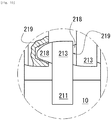
- a head portion 213 of fastener element 20 is provided with one engagement projection 218 projected frontward and an engagement recess 219 recessed frontward, and the engagement projection 218 and the engagement recess 219 are arranged oppositely in the front-rear direction.
- an engagement projection 218 of fastener element 20 positioned at the center is fitted into an engagement recess 219 of fastener element 20 positioned at front-side.
- the front-side fastener element 20 is shown in a partial cross-sectional view for clearly illustrating the engagement recess 219 of the front-side fastener element 20.
- the fastener stringer 30 shown in Fig. 9 can be manufactured in accordance with manufacturing methods of Figs. 7 and 8 .
- Figs. 11 and 12 have the same configuration with the slide fastener 100 shown in Fig. 1 .
- Fig. 11 is a picture showing a condition, after 5000 times of slider round trip test, of a slide fastener 100 having fastener elements 20 according to a comparative example.
- the fastener element 20 according to a comparative example has a metal base member 21 of red brass and a black-color surface resin layer 22 formed directly onto the metal base member 21.
- the surface resin layer 22 is a transparent resin into which carbon black is mixed.
- the resin material of the surface resin layer 22 is acrylic resin and its thickness is 10 ⁇ m.
- Fig. 12 is a picture showing a condition, after 5000 times of slider round trip test, of a slide fastener 100 having fastener elements 20 according to a working example.
- the fastener element 20 according to working example has a metal base member 21 of red brass, Ni layer 24, SnNi layer 25, and black-color SnCo layer 26, and a surface resin layer 22. Thickness of Ni layer 24 is 2 pm, thickness of SnNi layer 25 is 0.5 pm, thickness of the black-color SnCo layer 26 is 0.1 pm, and thickness of the surface resin layer 22 is 10 ⁇ m.
- the surface resin layer 22 is a transparent resin into which carbon black is mixed.
- the resin material of the surface resin layer 22 is acrylic resin.
- a ratio of area of the surface resin layer 22, which remains after 5000 times of slider round trip test, to area of the first surface 28 is between 85 to 99 %.
- a ratio of area of the surface resin layer 22, which remains after 5000 times of slider round trip test, to area of the first surface 28 is between 85 to 99 %.
- a ratio of exposed area of the exposure metal layer 26, which remains after 5000 times of slider round trip test, to area of the first surface 28 is between 1 to 15 %.
- the intermediate metal layer 23 is exposed which is an under-layer of the exposure metal layer 26, after 5000 times of slider round trip test.
- a ratio of this exposed area of the intermediate metal layer 23 to area of the first surface 28 is between 0.5 to 5 %.
- Fig. 13 and Fig. 14 have the same configuration with the slide fastener 100 shown in Fig. 9 .
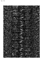
- Fig. 13 is a picture showing a condition, after 5000 times of slider round trip test, of a slide fastener 100 having fastener elements 20 according to a comparative example.
- the fastener element 20 according to a comparative example has a metal base member 21 of red brass and a black-color surface resin layer 22 formed directly onto the metal base member 21.
- the surface resin layer 22 is a transparent resin into which carbon black is mixed.
- the resin material of the surface resin layer 22 is acrylic resin and its thickness is 10 ⁇ m.
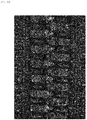
- Fig. 14 is a picture showing a condition, after 5000 times of slider round trip test, of a slide fastener 100 having fastener elements 20 according to a working example.
- the fastener element 20 according to a working example has a metal base member 21 of red brass, Ni layer 24, SnNi layer 25, and black-color SnCo layer 26, and a surface resin layer 22. Thickness of Ni layer 24 is 2 pm, thickness of SnNi layer 25 is 0.5 pm, thickness of the black-color SnCo layer 26 is 0.1 ⁇ m, and thickness of the surface resin layer 22 is 10 ⁇ m.
- the surface resin layer 22 is a transparent resin into which carbon black is mixed.
- the resin material of the surface resin layer 22 is acrylic resin.
- a ratio of area of the surface resin layer 22, which remains after 5000 times of slider round trip test, to area of the first surface 28 is between 85 to 99 %.
- a ratio of area of the surface resin layer 22, which remains after 5000 times of slider round trip test, to area of the first surface 28 is between 85 to 99 %.
- a ratio of exposed area of the exposure metal layer 26, which remains after 5000 times of slider round trip test, to area of the first surface 28 is between 1 to 15 %.
- the intermediate metal layer 23 is exposed which is an under-layer of the exposure metal layer 26, after 5000 times of slider round trip test.
- a ratio of this exposed area of the intermediate metal layer 23 to area of the first surface 28 is between 0.5 to 5 %.
Description
- The present disclosure is related to fastener stringers, methods of manufacturing the same, and slide fasteners.
-
Japanese Patent Application Laid-open No. 2005-144895 -
EP 2 653 050 A1 discloses a fastener stringer comprising: a fastener tape and a plurality of fastener elements attached to a side-edge portion of the fastener tape, wherein the fastener element comprises a metal base member and a single layered or multi layered surface resin layer formed on the metal base member. - A metal base member of a fastener element may be covered by a plated layer of a desired color, or a metal-oxide layer is formed onto a surface of a metal base member of a fastener element, thereby a desired color, including a chromatic color or achromatic color, of external appearance of fastener elements is achieved. However, the plated layer or the metal-oxide layer may wear off gradually as the number of times of round trip of slider increases, and external appearance of fastener elements may possible be changed. It is envisaged that, in a case where the number of times of round trip of slider exceeds 2 thousand or 3 thousand times, the plated layer or the metal-oxide layer may be removed widely and the metal base member may be exposed widely.
- A fastener stringer according to the present invention includes a fastener tape (10); and a plurality of fastener elements (20) attached to a side-edge portion of the fastener tape (10), wherein the fastener element (20) comprises: a metal base member (21); a single layered or multi layered surface resin layer (22) formed on the metal base member (21); and one or more intermediate metal layers (23) interposed between the metal base member (21) and the surface resin layer (22), wherein the one or more intermediate metal layers (23) include an exposure metal layer (26) that will be exposed by at least a partial removal of the surface resin layer (22), and wherein the surface resin layer (22) and the exposure metal layer (26) are made of material having the same color tone.
- In some embodiments, the surface resin layer (22) and the exposure metal layer (26) are made of material having black color tone.
- In some embodiments, the exposure metal layer (26) is a SnCo layer, and the one or more intermediate metal layers (23) includes a SnNi layer interposed between the metal base member (21) and the SnCo layer.
- In some embodiments, the one or more intermediate metal layers (23) further includes a Ni layer interposed between the metal base member (21) and the SnNi layer.
- In some embodiments, a thickness of the surface resin layer (22) is equal to or greater than 10 µm.
- A slide fastener according to further aspect of the present disclosure may include: a pair of the fastener stringers (30) as described above; and at least one slider (40) for opening and closing the pair of fastener stringers (30).
- A method of manufacturing a fastener stringer according to yet further aspect of the present disclosure is a method of manufacturing a fastener stringer that comprises a fastener tape (10) and a plurality of fastener elements (20) attached to a side-edge portion of the fastener tape (10), the method comprising: forming one or more intermediate metal layers (23) on a metal base member (21) of the fastener element (20); and forming a single layered or multi layered surface resin layer (22) on the one or more intermediate metal layers (23), wherein the one or more intermediate metal layers (23) include an exposure metal layer (26) that will be exposed by at least a partial removal of the surface resin layer (22), and wherein the surface resin layer (22) and the exposure metal layer (26) are made of material having the same color tone.
- In some embodiments, the surface resin layer (22) and the exposure metal layer (26) are made of material having black color tone.
- In some embodiments, a thickness of the surface resin layer (22) is equal to or greater than 10 µm.
- According to the present invention, it is possible to suppress an extent of change in external appearance of fastener elements regardless of the number of times of round trip of slider exceeding 2 thousand or 3 thousand times.
-
- [
Fig. 1] Fig. 1 is a schematic elevational view of a slide fastener according to an exemplary embodiment of the present disclosure. - [
Fig. 2] Fig. 2 is a schematic perspective view of a fastener element included in a slide fastener according to an exemplary embodiment of the present disclosure. - [
Fig. 3] Fig. 3 is a schematic view in which a rear mouth of a slider is viewed in elevation in a slide fastener according to an exemplary embodiment of the present disclosure, a pull tab of a slider is in an upstanding state. - [
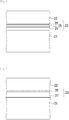
Fig. 4] Fig. 4 is a schematic view showing a lamination structure of a fastener element according to an exemplary embodiment of the present disclosure. - [
Fig. 5] Fig. 5 is a schematic view showing a lamination structure of a fastener element according to an exemplary embodiment of the present disclosure. - [
Fig. 6] Fig. 6 is an expanded partial view of engaged fastener elements of a slide fastener according to an exemplary embodiment of the present disclosure. - [
Fig. 7] Fig. 7 is a schematic flowchart showing a method of manufacturing a slide fastener according to an exemplary embodiment of the present disclosure. - [
Fig. 8] Fig. 8 is a schematic flowchart showing a method of manufacturing a slide fastener according to an exemplary embodiment of the present disclosure. - [
Fig. 9] Fig. 9 is a schematic elevational view of a slide fastener according to another exemplary embodiment of the present disclosure. - [
Fig. 10] Fig. 10 is a schematic view showing an engaged state of left and right elements of a slide fastener according to another exemplary embodiment of the present disclosure. - [
Fig. 11] Fig. 11 is a picture showing fastener elements of a slide fastener after a sliding test according to a comparative example. - [
Fig. 12] Fig. 12 is a picture showing fastener elements of a slide fastener after a sliding test according to a working example. - [
Fig. 13] Fig. 13 is a picture showing fastener elements of a slide fastener after a sliding test according to a comparative example. - [
Fig. 14] Fig. 14 is a picture showing fastener elements of a slide fastener after a sliding test according to a working example. - Hereinafter, non-limiting exemplary embodiments of the present invention will be described with references to
Figs. 1 to 14 . One or more disclosed exemplary embodiments and respective features included in the exemplary embodiment are not mutually exclusive. A skilled person would properly combine the respective exemplary embodiments and/or respective features without requiring excess descriptions. A skilled person would also understand synergic effect by such combination. Overlapping descriptions among exemplary embodiments will be basically omitted. Referenced drawings are mainly for the purpose of illustrating an invention and may possibly be simplified for the sake of convenience of illustration. - A
slide fastener 100 shown inFig. 1 has a left-right pair offastener stringers 30, and aslider 40 for opening and closing the left-right pair offastener stringers 30. Frontward movement of theslider 40 opens the left-right fastener stringers 30, and rearward movement of theslider 40 closes the left-right fastener stringers 30. Front-rear direction is equal to a direction of movement ofslider 40. Left-right direction is equal to a direction of side-by-side arrangement offastener stringers 30. The left-right direction is orthogonal to the front-rear direction. Up-down direction is orthogonal to the front-rear direction and the left-right direction. - Each
fastener stringer 30 has afastener tape 10, and a plurality offastener elements 20 attached to a side-edge portion of thefastener tape 10. Thefastener tape 10 of one of the left-right fastener stringers 30 has a side-edge portion that is opposed to thefastener tape 10 of the other one of the left-right fastener stringers 30. The plurality of thefastener element 20 is attached to this side-edge portion. - In some cases, the
fastener element 20 is manufactured through a step of die-cutting, by using a punch having an outer shape corresponding to afastener element 20, a metal plate that has a thickness corresponding to a thickness offastener element 20. In some cases, thefastener element 20 is manufactured through a step of cutting, by a cutter at a length corresponding to a thickness offastener element 20, an elongated element-base (element-mother) member that has a terminal shape corresponding to afastener element 20. Afterward, each fastener element obtained by the die-cutting of metal plate or the cutting of the element-base member may be pressed, if necessary. Then, after passing through at least steps of plating and coating, thefastener elements 20 are attached to the side-edge portion of thefastener tape 10 by a swaging apparatus. At the time of this attachment, thefastener elements 20 will be plastically deformed. In another case, thefastener elements 20 are attached to thefastener tape 10 in arbitrary way, then thefastener elements 20 are plated and coated. - The
fastener tape 10 is a woven or knitted fabric for example, and is a cloth having a flexibility. Thefastener element 20 has a pair oflegs fastener tape 10 or a core thread provided there as schematically shown inFig. 2 , and anengagement head 213 coupled to the pair oflegs legs fastener element 20 being attached to the side-edge portion of the fastener tape. Theengagement head 213 is provided outwardly of fastener tape relative to the pair oflegs - The
engagement head 213 of thefastener element 20 has afirst projection 214 being projected frontward and asecond projection 215 being projected rearward at the opposite side of thefirst projection 214. Theengagement head 213 of thefastener element 20 further has afirst recess 216 being recessed at a position between the side-edge portion of thefastener tape 10 and thefirst projection 214, and asecond recess 217 being recessed at a position between the side-edge portion of thefastener tape 10 and the second projection. Afastener element 20 of one of the left-right fastener stringers 30 is inserted into a space betweenadjacent fastener elements 20 in front-rear direction of the other one of the left-right fastener stringers 30. Thefirst projection 214 of thatfastener element 20 inserted between theadjacent fastener elements 20 in front-rear direction is fitted to thesecond recess 217 of the adjacent front-side fastener element 20, and thesecond projection 215 of thatfastener element 20 is fitted to thefirst recess 216 of the adjacent rear-side fastener element 20. - Each
fastener stringer 30 has afront stop 50 that is provided adjacent to and at a front-side of a line of elements in whichfastener elements 20 are arranged, and arear stop 60 that is provided adjacent to and at a rear-side of the line of elements. The front stops 50 are separately provided to the respective left-right fastener stringers 30. Therear stop 60 is commonly provided to the left-right fastener stringers 30. In some cases, stops different from the illustrated ones may be employed. - As schematically shown in
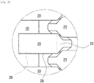
Fig. 3 , theslider 40 has atop wing 41, abottom wing 42 arranged to be opposed to thetop wing 41, acoupling pillar 43 interconnecting thetop wing 41 and thebottom wing 42, a pull-attachment column 44 provided at the top surface of thetop wing 41, and apull tab 45 attached to the pull-attachment column 44.Flange portions top wing 41 and thebottom wing 42. Theflange portion 46 of thetop wing 41 is projected toward thebottom wing 42. Theflange portion 47 of thebottom wing 42 is projected toward thetop wing 41. Theslider 40 has twofront mouths 48 at left-right positions of thecoupling pillar 43. Theslider 40 has onerear mouth 49 at the opposite side of the twofront mouths 48. Y-like element passage is provided between the twofront mouths 48 and the onerear mouth 49. The element passage is provided between thetop wing 41 and thebottom wing 42 and is defined by them in up-down direction. The element passage is also defined by theflange portion 46 of thetop wing 41 and theflange portion 47 of thebottom wing 42 from out-side in left-right direction. - When a
fastener element 20 moves between thefront mouth 48 and therear mouth 49 of theslider 40, the top surface of thefastener element 20 touches thetop wing 41, the bottom surface of thefastener element 20 touches thebottom wing 42, and theengagement head 213 of thefastener element 20 touches thecoupling pillar 43, andlegs fastener element 20 touches theflange portion 46 of thetop wing 41 and theflange portion 47 of thebottom wing 42. When thefastener element 20 moves while touching thetop wing 41, thebottom wing 42, thecoupling pillar 43 or theflange portion fastener element 20 may wear off. It is considered that an extent of wear of surface offastener element 20 is proportional to the number of times of round trip ofslider 40. - As shown in
Figs. 4 and 5 , thefastener element 20 includes ametal base member 21 that is made of a metal. Themetal base member 21 includes relatively soft metal from a view point of workability. In some cases, themetal base member 21 is made of a single metal. The exemplary single metal includes iron (Fe), zinc (Zn) or aluminum (Al), for example. In some cases, themetal base member 21 is made of an alloy that includes a plurality of metal elements. Copper-zinc alloy (CuZn), copper-zinc-nickel alloy (CuZnNi), red brass, brass or copper-zinc-manganese alloy (CuZnMn) can be used as an exemplary alloy. - As shown in
Figs. 4 and 5 , thefastener element 20 includes a single layered or multi layeredsurface resin layer 22 formed on themetal base member 21, and one or moreintermediate metal layers 23 interposed between themetal base member 21 and thesurface resin layer 22. The one or more intermediate metal layers 23 includes anexposure metal layer 26 that will be exposed by at least a partial removal of thesurface resin layer 22. Note that, in a case where theintermediate metal layer 23 is a single layer, theintermediate metal layer 23 is equal to theexposure metal layer 26. - As described at the beginning, it is envisaged that, in a case where the number of times of round trip of slider exceeds 2 thousand or 3 thousand times, the plated layer or the metal-oxide layer formed on the
metal base member 21 of thefastener element 20 may be removed widely and the metal base member may be exposed widely. In order to solve this problem, it may be considered to cover themetal base member 21 of thefastener element 20 with an extremely-high-rigidity surface metal layer. However, even employing the extremely-high-rigidity surface metal layer, it may be not possible to avoid the emergence of wear in a case where the number of times of round trip of slider exceeds 2 thousand or 3 thousand times or in a case where it reaches up to 5000 times. - In light of the above consideration, the present inventors have newly recognized that it is not a realistic approach to cover the
metal base member 21 with a layer that will never wear and never be removed. Based on this finding, the present inventors have newly discovered that a realistic way would be adopting asurface resin layer 22 which is expected to be removed by wear undoubtedly, and adopting anexposure metal layer 26 which will be exposed by wear of thesurface resin layer 22, wherein thesurface resin layer 22 and theexposure metal layer 26 are configured to have the same color tone. According to such a configuration, at the initial stage of wear, exposure of thesurface resin layer 22 will continue, and initial color of thefastener element 20 is thus maintained. Even if wear of thesurface resin layer 22 progresses and theexposure metal layer 26 is exposed, a partial removal of thesurface resin layer 22 is not distinctive as the color of theexposure metal layer 26 and the color of thesurface resin layer 22 are the same tone. Even wear of thesurface resin layer 22 progresses much further, this would just result in increase of exposed area of theexposure metal layer 26, thereby avoiding or suppressing remarkable change in external appearance of thefastener element 20. Wear of thesurface resin layer 22 and theexposure metal layer 26 progresses gradually. Therefore, the change in external appearance offastener element 20 is also moderate. Note that the colors of thesurface resin layer 22 and theexposure metal layer 26 include an achromatic color or chromatic color. In some cases, colors of thesurface resin layer 22 and theexposure metal layer 26 are accompanied by luster or metallic luster. Metal includes a single metal or alloy. - The color of
surface resin layer 22 is determined by color of resin forming thissurface resin layer 22 and/or color of additive that is mixed into thissurface resin layer 22. The additive mixed into thesurface resin layer 22 may be inorganic pigment, metal powder, organic pigment or dye, for example. The color of theexposure metal layer 26 is determined by color of metal forming thisexposure metal layer 26, i.e. spectral reflectance of the metal. Note that an exemplaryexposure metal layer 26 is made of a single metal. Another exemplaryexposure metal layer 26 is made of an alloy that includes a plurality of metal elements. - "The same color tone" stated in this specification basically indicates that they are seen as the same color under illumination of white light seen by a human having a normal sight and color vision. The same color is evaluated from at least one aspect of hue, brightness, and chroma. White LED or fluorescent light is employed as an illuminating source. The same color includes color-difference that is not perceivable by human. A range of color in which human eyes cannot distinguish is called a color identification gamut.
- In a case where colors to be compared are achromatic color, brightness of color will be taken into account to compare. The achromatic color includes black, white and gray that is an intermediate color between black and white. A case is assumed where brightness of black is set to be 0, brightness of white is set to be 10, and brightness of gray between the black and white is set to be 1 to 9.
- In a case where colors to be compared have metallic luster, degree of similarity of spectral reflectance (reflectance spectrum) of colors may be taken into account to compare. For example, gold (Au), silver (Ag) and copper (Cu) each has a distinguishable spectral reflectance (reflectance spectrum). Reflectance of gold changes greatly around 500 nm, and yellow and red colors are more reflected than blue color. Silver has a high reflectance over a wide range of visual band from blue color to red color of 400 nm to 700 nm.
- In a case where the
surface resin layer 22 has a metallic luster, thesurface resin layer 22 is made of a resin into which metal powder is mixed. The metal powder exists in the internal of thesurface resin layer 22, and thus metallic luster of thesurface resin layer 22 is maintained even if wear of thesurface resin layer 22 progresses. - In an example described with reference to
Fig. 4 , thesurface resin layer 22 and theexposure metal layer 26 have black color tone. That is, thesurface resin layer 22 and theexposure metal layer 26 are made of material of black color tone. Change of the external appearance of thefastener element 20 is suppressed even if theexposure metal layer 26 is exposed due to progress of wear of thesurface resin layer 22. - In a specific example, the
surface resin layer 22 is made of a transparent resin into which black pigment is mixed. Theexposure metal layer 26 is made of a metal layer of black color. Theintermediate metal layer 23 between theexposure metal layer 26 and themetal base member 21 includesNi layer 24 andSnNi layer 25. Themetal base member 21 is made of a red brass. - The
surface resin layer 22 can include a synthetic resin such as a melamine resin, alkyd resin, acrylic resin, epoxy resin, polyurethane resin, vinyl chloride resin, silicone resin, and fluorine resin. Pigment to be mixed into thesurface resin layer 22 includes carbon black or black color natural mineral, for example. Thesurface resin layer 22 can include ingredients not described in this specification. The thickness of thesurface resin layer 22 is between 5 to 20 pm, for example. - The
exposure metal layer 26 can include black color nickel-zinc (Ni-Zn) alloy, black color tin-nickel (Sn-Ni) alloy, black color tin-cobalt (Sn-Co) alloy or black color chrome, for example. The thickness of theexposure metal layer 26 is between 0.05 to 2 µm, for example. - The
Ni layer 24 is provided mainly for securing wear resistance of thefastener element 20. The thickness of Ni layer is between 0.5 to 5 pm, for example. TheSnNi layer 25 is formed to suppress elution of Ni layer. The thickness of the SnNi layer25 is between 0.1 to 1 µm, for example. - The
surface resin layer 22 is formed by a step of coating. Theexposure metal layer 26 is formed by a step of plating.Ni layer 24 andSnNi layer 25 are also formed by a step of plating. An electroplating and so on can be suggested as examples of the step of plating. Various conditions of each step may be determined properly by a skilled person in the art. Note that, it is possible to omit theNi layer 24 by forming theSnNi layer 25 thicker. - In some specific embodiments, the thickness of the
surface resin layer 22 is greater than the total thickness of theintermediate metal layer 23. In some cases, thesurface resin layer 22 has a thickness equal to or greater than 10 µm or 15 µm or 20µm. In some cases, thesurface resin layer 22 has a thickness equal to or less than 1 µm or 5 µm or 10 µm. In a case where the thickness of thesurface resin layer 22 is great, thefastener element 20 may likely touch theslider 40 when thefastener element 20 moves through theslider 40. However, if the thickness of thesurface resin layer 22 is great, then the number of round trip of slider required for wear of thesurface resin layer 22 is expected to increase. - In another example described with reference to
Fig. 4 , thesurface resin layer 22 and theexposure metal layer 26 have gold color tone. In this case either, change in the external appearance of thefastener element 20 is suppressed even if theexposure metal layer 26 is exposed due to progress of wear of thesurface resin layer 22. - In a specific example, the
surface resin layer 22 is made of a transparent resin into which gold-color metal powder is mixed. Theexposure metal layer 26 is made of gold (Au) or gold-color copper-tin (CuSn) alloy or gold-color copper-zinc (CuZn) alloy.Ni layer 24 andSnNi layer 25 are formed between theexposure metal layer 26 and themetal base member 21. Themetal base member 21 is made of iron, zinc or nickel silver. The gold-color metal powder mixed into thesurface resin layer 22 is a powder of gold (Au) or gold-color copper-tin (CuSn) alloy or gold-color copper-zinc (CuZn) alloy. Note that, it is possible to omit theNi layer 24 by forming theSnNi layer 25 thicker. - In yet another example described with reference to
Fig. 4 , thesurface resin layer 22 and theexposure metal layer 26 have copper color tone, i.e. reddish gloss color. In this case either, change in the external appearance of thefastener element 20 is suppressed even if theexposure metal layer 26 is exposed due to progress of wear of thesurface resin layer 22. - In a specific example, the
surface resin layer 22 is made of a transparent resin into which copper-color metal powder is mixed. Theexposure metal layer 26 is made of copper cyanide or copper sulfate or copper pyrophosphate.Ni layer 24 and Sn-Ni layer 25 are formed between theexposure metal layer 26 and themetal base member 21. Themetal base member 21 is made of red brass, nickel silver, iron or zinc. The copper-color metal powder mixed into thesurface resin layer 22 is a powder of copper cyanide or copper sulfate or copper pyrophosphate, for example. Note that, it is possible to omit theNi layer 24 by forming theSnNi layer 25 thicker. - In an example described with reference to
Fig. 5 , thesurface resin layer 22 and theexposure metal layer 26 have black color tone. Change of the external appearance of thefastener element 20 is suppressed even if theexposure metal layer 26 is exposed due to progress of wear of thesurface resin layer 22. - In a specific example, the
surface resin layer 22 is made of a transparent resin into which black pigment is mixed. Theexposure metal layer 26 is made of a metal layer having black color. In particular, theexposure metal layer 26 is made of black-color Sn-Co layer. Sn-Ni layer 27 is formed between theexposure metal layer 26 and themetal base member 21. Themetal base member 21 is made of a red brass. - In another example described with reference to
Fig. 5 , thesurface resin layer 22 and theexposure metal layer 26 have silver color tone, and have whitish gross color. Change of the external appearance of thefastener element 20 is suppressed even if theexposure metal layer 26 is exposed due to progress of wear of thesurface resin layer 22. - In a specific example, the
surface resin layer 22 is made of a transparent resin into which silver-color metal powder is mixed. Theexposure metal layer 26 is made of silver-color metal layer. In particular, theexposure metal layer 26 is made of silver-color Sn-Ni layer.Ni layer 27 is formed between theexposure metal layer 26 and themetal base member 21. Themetal base member 21 is made of red brass. - As shown in
Fig. 6 , thefastener element 20 has afirst surface 28 arranged at one side of thefastener tape 10 and a second surface that extends toward a terminal end of the engagement head. Thefirst surface 28 is a flat surface that is opposed to thetop wing 41 of theslider 40 and arranged substantially parallel to the inner surface of thetop wing 41 that is opposed to thebottom wing 42. Thefirst surface 28 is a top surface of thefastener element 20 which touches thetop wing 41 when thefastener element 20 moves between thefront mouth 48 and therear mouth 49 of theslider 40. Thesecond surface 29 is a sloped surface or curved surface that is downwardly sloped toward the terminal end of the engagement head. In other words, thesecond surface 29 is sloped or curved in a direction away from the opposed inner surface of thetop wing 41 as extending away from thefirst surface 28. - In some cases described above, area of the
surface resin layer 22 which remains after 5000 times of slider round trip test is between 90 to 99 % or 80 to 90 % or 70 to 80 % of area of thefirst surface 28. A ratio of exposed area of theexposure metal layer 26, after 5000 times of slider round trip test, to area of thefirst surface 28 is between 1 to 10 %, or 10 to 20% or 20 to 30 %. There are cases where theintermediate metal layer 23 is exposed which is an under-layer of theexposure metal layer 26, after 5000 times of slider round trip test. However, a ratio of exposed area of theintermediate metal layer 23 to area of thefirst surface 28 is between 1 to 3 %, or 3 to 7% or 7 to 10 %. - In some embodiments described above, fastener elements are manufactured in accordance with flowcharts of
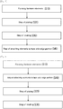
Figs. 7 and 8 , and then are attached to side-edge portions of fastener tapes. In a case ofFig. 7 , at step S10, firstly fastener elements are manufactured. The step S10 may be accompanied by the above-described die-cutting or cutting processes. In some cases, the step S10 includes a step of die-cutting, by using a punch having an outer shape corresponding to a fastener element, a metal plate having a thickness corresponding to a thickness of fastener element. In some cases, the step S10 includes a step of cutting, by a cutter at a length corresponding to a thickness of fastener element, an elongated element-base member that has a terminal shape corresponding to a fastener element. The step S10 may additionally include a step of pressing each fastener element obtained by the die-cutting of the metal plate or the cutting of the element-base member. - Next, at step S20, fastener elements are plated. A fastener element made of a
metal base member 21 which is obtained by the step of die-cutting or cutting and which is not plated and coated will be covered by one or moreintermediate metal layers 23 and theexposure metal layer 26 in this order through a step of plating. As shown inFigs. 4 and 5 , in cases where a plurality of metal layers is formed, plural times of plating are done for forming the plurality of metal layers. Therefore, in some cases, fastener elements are immersed in plural plating tanks and transferred between the plural plating tanks. In an exemplary embodiment shown inFig. 4 ,Ni layer 24 is formed by a step of Ni-plating,SnNi layer 25 is formed by a step of SnNi-plating, andexposure metal layer 26 made of black-color NiZn alloy is formed by black-color NiZn alloy plating. TheNi layer 24, the SnNi layer25, and the black-color NiZn alloy layer are formed successively on themetal base member 21. Note that the step of plating can include a step of electroplating or electroless plating. The composition of plating solution stored in a plating tank will be preferably determined in accordance with a desired composition of plated layers to be formed in the fastener element. - Next, at step S30, the fastener element is coated after the step of plating. The fastener element after the step of plating is covered by a single layered or multi layered
surface resin layer 22 through a step of coating. It is possible to coat the fastener elements by immersing the fastener elements into a coating solution or spraying a coating liquid to the fastener elements. In an exemplary embodiment shown inFig. 4 described above, a black-colorsurface resin layer 22 is laminated onto the above-described black-color NiZn alloy layer. The composition of coating solution will be preferably determined in accordance with a desired composition of surface resin layer to be formed in the fastener element. - Next, at step S40, the fastener element is attached to the side-edge portion of the fastener tape. Specifically, a spacing between a pair of legs of fastener element is reduced by a swaging apparatus, and the side-edge portion of fastener tape is sandwiched by the pair of legs of fastener element. In some cases, additionally to steps S10 to S40, washing step, heating step or drying step may be performed.
- In a case shown in
Fig. 8 , fastener elements are attached to a side-edge portion of a fastener tape before steps of plating and coating.Fastener stringers 30 can be manufactured suitably even in such a method. Description is omitted as method ofmanufacturing slide fasteners 100 fromfastener stringers 30 has been widely known in this art. - In some embodiments, a
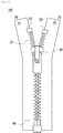
slide fasteners 100 shown inFigs. 9 and10 is presented. In theslide fastener 100 shown inFig. 9 , fastener element 20s having a different shape withfastener elements 20 of theslide fastener 100 shown inFig. 1 are employed. Even in this case, similar technical effects as above can be obtained. Note that a rear stop shown inFig. 9 is called a separable stop and has a structure which allows separation of left andright fastener stringers 30. - As shown in
Fig. 10 , ahead portion 213 offastener element 20 is provided with oneengagement projection 218 projected frontward and anengagement recess 219 recessed frontward, and theengagement projection 218 and theengagement recess 219 are arranged oppositely in the front-rear direction. As shown inFig. 10 , with respect to the illustrated threefastener elements 20, anengagement projection 218 offastener element 20 positioned at the center is fitted into anengagement recess 219 offastener element 20 positioned at front-side. InFig. 10 , the front-side fastener element 20 is shown in a partial cross-sectional view for clearly illustrating theengagement recess 219 of the front-side fastener element 20. Note that thefastener stringer 30 shown inFig. 9 can be manufactured in accordance with manufacturing methods ofFigs. 7 and 8 . -
Figs. 11 and12 have the same configuration with theslide fastener 100 shown inFig. 1 .Fig. 11 is a picture showing a condition, after 5000 times of slider round trip test, of aslide fastener 100 havingfastener elements 20 according to a comparative example. Thefastener element 20 according to a comparative example has ametal base member 21 of red brass and a black-colorsurface resin layer 22 formed directly onto themetal base member 21. Thesurface resin layer 22 is a transparent resin into which carbon black is mixed. The resin material of thesurface resin layer 22 is acrylic resin and its thickness is 10 µm. -
Fig. 12 is a picture showing a condition, after 5000 times of slider round trip test, of aslide fastener 100 havingfastener elements 20 according to a working example. Thefastener element 20 according to working example has ametal base member 21 of red brass,Ni layer 24,SnNi layer 25, and black-color SnCo layer 26, and asurface resin layer 22. Thickness ofNi layer 24 is 2 pm, thickness ofSnNi layer 25 is 0.5 pm, thickness of the black-color SnCo layer 26 is 0.1 pm, and thickness of thesurface resin layer 22 is 10 µm. Thesurface resin layer 22 is a transparent resin into which carbon black is mixed. The resin material of thesurface resin layer 22 is acrylic resin. - As would be understood from comparison between
Fig. 11 andFig. 12 , in the case of comparative example ofFig. 11 , the remaining region of the surface resin layer is narrow and contrast between black-color and silver-white-color is noticeable. On the other hand, in the case of the working example ofFig. 12 , the remaining region of thesurface resin layer 22 is wider than the comparative example ofFig. 11 , and contrast between black-color and silver-white-color is suppressed because thesurface resin layer 22 and theexposure metal layer 26 have the same color tone. - In the comparative example of
Fig. 11 , a ratio of area of thesurface resin layer 22, which remains after 5000 times of slider round trip test, to area of thefirst surface 28 is between 85 to 99 %. - In the working example of
Fig. 12 , a ratio of area of thesurface resin layer 22, which remains after 5000 times of slider round trip test, to area of thefirst surface 28 is between 85 to 99 %. A ratio of exposed area of theexposure metal layer 26, which remains after 5000 times of slider round trip test, to area of thefirst surface 28 is between 1 to 15 %. Theintermediate metal layer 23 is exposed which is an under-layer of theexposure metal layer 26, after 5000 times of slider round trip test. A ratio of this exposed area of theintermediate metal layer 23 to area of thefirst surface 28 is between 0.5 to 5 %. -
Fig. 13 andFig. 14 have the same configuration with theslide fastener 100 shown inFig. 9 .Fig. 13 is a picture showing a condition, after 5000 times of slider round trip test, of aslide fastener 100 havingfastener elements 20 according to a comparative example. Thefastener element 20 according to a comparative example has ametal base member 21 of red brass and a black-colorsurface resin layer 22 formed directly onto themetal base member 21. Thesurface resin layer 22 is a transparent resin into which carbon black is mixed. The resin material of thesurface resin layer 22 is acrylic resin and its thickness is 10 µm. -
Fig. 14 is a picture showing a condition, after 5000 times of slider round trip test, of aslide fastener 100 havingfastener elements 20 according to a working example. Thefastener element 20 according to a working example has ametal base member 21 of red brass,Ni layer 24,SnNi layer 25, and black-color SnCo layer 26, and asurface resin layer 22. Thickness ofNi layer 24 is 2 pm, thickness ofSnNi layer 25 is 0.5 pm, thickness of the black-color SnCo layer 26 is 0.1 µm, and thickness of thesurface resin layer 22 is 10 µm. Thesurface resin layer 22 is a transparent resin into which carbon black is mixed. The resin material of thesurface resin layer 22 is acrylic resin. - As would be understood from comparison of
Figs. 13 and14 , in a case of comparative example ofFig. 13 , red brass is exposed at regions ofleg portion 212 offastener element 20 which are positioned outwardly of fastener tape. Color difference between red brass and black-colorsurface resin layer 22 is presented noticeably, and thus change in external appearance offastener element 20 would be noticeable for users. In a case of working example ofFig. 14 , such color change in external appearance offastener element 20 is not noticeable for users. - In the comparative example of
Fig. 13 , a ratio of area of thesurface resin layer 22, which remains after 5000 times of slider round trip test, to area of thefirst surface 28 is between 85 to 99 %. - In the working example of
Fig. 14 , a ratio of area of thesurface resin layer 22, which remains after 5000 times of slider round trip test, to area of thefirst surface 28 is between 85 to 99 %. A ratio of exposed area of theexposure metal layer 26, which remains after 5000 times of slider round trip test, to area of thefirst surface 28 is between 1 to 15 %. Theintermediate metal layer 23 is exposed which is an under-layer of theexposure metal layer 26, after 5000 times of slider round trip test. A ratio of this exposed area of theintermediate metal layer 23 to area of thefirst surface 28 is between 0.5 to 5 %. - Given the above teachings, a skilled person in the art would be able to add various modifications to the respective embodiments. Reference codes in Claims are just for reference and should not be referenced for purposes of narrowly construing the scope of claims. The specific shapes of fastener element should not be limited to ones disclosed in this specification.
-
- 10
- the fastener tape
- 20
- the fastener element
- 21
- the metal base member
- 22
- the surface resin layer
- 23
- the intermediate metal layer
- 26
- the exposure metal layer
- 30
- the fastener stringer
Claims (9)
- A fastener stringer (30) comprising:a fastener tape (10); anda plurality of fastener elements (20) attached to a side-edge portion of the fastener tape (10), whereinthe fastener element (20) comprises:a metal base member (21);a single layered or multi layered surface resin layer (22) formed on the metal base member (21);
andone or more intermediate metal layers (23) interposed between the metal base member (21) and the surface resin layer (22), whereinthe one or more intermediate metal layers (23) include an exposure metal layer (26) that will be exposed by at least a partial removal of the surface resin layer (22), characterized in thatthe surface resin layer (22) and the exposure metal layer (26) are made of material having the same color tone. - The fastener stringer of Claim 1, wherein the surface resin layer (22) and the exposure metal layer (26) are made of material having black color tone.
- The fastener stringer of Claim 1 or 2, wherein the exposure metal layer (26) is a SnCo layer, and the one or more intermediate metal layers (23) includes a SnNi layer interposed between the metal base member (21) and the SnCo layer.
- The fastener stringer of Claim 3, wherein the one or more intermediate metal layers (23) further includes a Ni layer interposed between the metal base member (21) and the SnNi layer.
- The fastener stringer of any one of Claims 1 to 4, wherein a thickness of the surface resin layer (22) is equal to or greater than 10 µm.
- A slide fastener comprising:a pair of the fastener stringers (30) of any one of Claims 1 to 5; andat least one slider (40) for opening and closing the pair of fastener stringers (30).
- A method of manufacturing a fastener stringer that comprises a fastener tape (10) and a plurality of fastener elements (20) attached to a side-edge portion of the fastener tape (10), the method comprising:forming one or more intermediate metal layers (23) on a metal base member (21) of the fastener element (20); andforming a single layered or multi layered surface resin layer (22) on the one or more intermediate metal layers (23), whereinthe one or more intermediate metal layers (23) include an exposure metal layer (26) that will be exposed by at least a partial removal of the surface resin layer (22), characterized in thatthe surface resin layer (22) and the exposure metal layer (26) are made of material having the same color tone.
- The method of manufacturing a fastener stringer of Claim 7, wherein the surface resin layer (22) and the exposure metal layer (26) are made of material having black color tone.
- The method of manufacturing a fastener stringer of Claim 7 or 8, wherein a thickness of the surface resin layer (22) is equal to or greater than 10 µm.
Applications Claiming Priority (1)
| Application Number | Priority Date | Filing Date | Title |
|---|---|---|---|
| PCT/JP2015/081787 WO2017081777A1 (en) | 2015-11-11 | 2015-11-11 | Fastener stringer, method for manufacturing same, and slide fastener |
Publications (3)
| Publication Number | Publication Date |
|---|---|
| EP3375317A1 EP3375317A1 (en) | 2018-09-19 |
| EP3375317A4 EP3375317A4 (en) | 2019-05-08 |
| EP3375317B1 true EP3375317B1 (en) | 2021-06-30 |
Family
ID=58696022
Family Applications (1)
| Application Number | Title | Priority Date | Filing Date |
|---|---|---|---|
| EP15908297.3A Active EP3375317B1 (en) | 2015-11-11 | 2015-11-11 | Fastener stringer, method for manufacturing same, and slide fastener |
Country Status (5)
| Country | Link |
|---|---|
| EP (1) | EP3375317B1 (en) |
| JP (1) | JP6599475B2 (en) |
| CN (1) | CN108348047B (en) |
| TW (1) | TWI644634B (en) |
| WO (1) | WO2017081777A1 (en) |
Families Citing this family (2)
| Publication number | Priority date | Publication date | Assignee | Title |
|---|---|---|---|---|
| CN111990732B (en) * | 2019-05-27 | 2022-11-01 | 浙江伟星实业发展股份有限公司 | Tooth combining metal and resin and preparation method thereof |
| IT202100007925A1 (en) * | 2021-03-31 | 2022-10-01 | Ykk Corp | METHODS FOR MANUFACTURING ZIPPER TAPE WITH COLORED METALLIC TEETH |
Family Cites Families (9)
| Publication number | Priority date | Publication date | Assignee | Title |
|---|---|---|---|---|
| JPS5793003A (en) * | 1980-12-01 | 1982-06-09 | Yoshida Kogyo Kk | Slide fastener chain having metal tooth and production thereof |
| JPH07110245B2 (en) * | 1989-06-09 | 1995-11-29 | ワイケイケイ株式会社 | Fusner element for slide fasteners |
| JPH0824019A (en) * | 1994-07-18 | 1996-01-30 | Ykk Kk | Personal ornament |
| KR100467113B1 (en) * | 2001-01-31 | 2005-01-24 | 가부시키가이샤 구라레 | Aqueous resin composition, and method of manufacturing a separable fastener using this composition |
| WO2004024987A1 (en) * | 2002-08-30 | 2004-03-25 | Toto Ltd. | Method of treatment for reducing elution of lead from lead containing copper alloy and waterwork utensils made from lead containing copper alloy |
| JP4071095B2 (en) * | 2002-12-04 | 2008-04-02 | Ykk株式会社 | Reflective slide fastener |
| EP2517593B1 (en) * | 2009-12-25 | 2015-11-11 | YKK Corporation | Zipper component and slide zipper |
| JP5579276B2 (en) * | 2010-12-17 | 2014-08-27 | Ykk株式会社 | Fastener stringer, fastener chain, and fastener chain manufacturing method |
| US9493860B2 (en) * | 2012-04-04 | 2016-11-15 | Nippon Steel & Sumitomo Metal Corporation | Chromium-containing austenitic alloy |
-
2015
- 2015-11-11 CN CN201580084542.4A patent/CN108348047B/en active Active
- 2015-11-11 WO PCT/JP2015/081787 patent/WO2017081777A1/en active Application Filing
- 2015-11-11 EP EP15908297.3A patent/EP3375317B1/en active Active
- 2015-11-11 JP JP2017549925A patent/JP6599475B2/en active Active
-
2016
- 2016-10-12 TW TW105132840A patent/TWI644634B/en active
Non-Patent Citations (1)
| Title |
|---|
| None * |
Also Published As
| Publication number | Publication date |
|---|---|
| TWI644634B (en) | 2018-12-21 |
| TW201715987A (en) | 2017-05-16 |
| CN108348047B (en) | 2020-10-02 |
| CN108348047A (en) | 2018-07-31 |
| EP3375317A4 (en) | 2019-05-08 |
| EP3375317A1 (en) | 2018-09-19 |
| JPWO2017081777A1 (en) | 2018-07-05 |
| JP6599475B2 (en) | 2019-10-30 |
| WO2017081777A1 (en) | 2017-05-18 |
Similar Documents
| Publication | Publication Date | Title |
|---|---|---|
| KR100482244B1 (en) | Slide fastener and method of manufacturing attachment having constituent members | |
| EP3375317B1 (en) | Fastener stringer, method for manufacturing same, and slide fastener | |
| KR102178027B1 (en) | Absence of slide fasteners or buttons made of plated aluminum or aluminum alloy | |
| EP2653050A1 (en) | Fastener stringer and fastener chain, and method for manufacturing fastener chain | |
| TWI627296B (en) | Metal fastener member with light golden color and fastener member having the same | |
| US2264580A (en) | Method of making separable fasteners | |
| WO2014141409A1 (en) | Slide fastener chain, slide fastener and slide fastener production method | |
| TWI641338B (en) | Chain cloth, zipper and chain cloth having the same | |
| CN111278324A (en) | Slide fastener | |
| CN102715713A (en) | Zipper | |
| CN102742981B (en) | Zipper wire material and zipper tooth made of zipper wire material | |
| TWI649463B (en) | Zipper chain and zipper with copper alloy sprocket | |
| US2264326A (en) | Method of making separable fasteners | |
| US20220347590A1 (en) | Model part and method for manufacturing model part | |
| WO2022210222A1 (en) | Method for producing slide fastener stringer having colored metal element, metal element, slide fastener stringer and slide fastener chain | |
| CN210274148U (en) | Gradient glass cover plate | |
| CN217906561U (en) | Wear-resistant metal button | |
| JP6389069B2 (en) | Plated composite product and its manufacturing method | |
| TW201615119A (en) | Fastener stringer and slide fastener provided with same | |
| CN105831899A (en) | Fastener stringer with colored metal components and method for preparing the same and fastener |
Legal Events
| Date | Code | Title | Description |
|---|---|---|---|
| STAA | Information on the status of an ep patent application or granted ep patent |
Free format text: STATUS: THE INTERNATIONAL PUBLICATION HAS BEEN MADE |
|
| PUAI | Public reference made under article 153(3) epc to a published international application that has entered the european phase |
Free format text: ORIGINAL CODE: 0009012 |
|
| STAA | Information on the status of an ep patent application or granted ep patent |
Free format text: STATUS: REQUEST FOR EXAMINATION WAS MADE |
|
| 17P | Request for examination filed |
Effective date: 20180608 |
|
| AK | Designated contracting states |
Kind code of ref document: A1 Designated state(s): AL AT BE BG CH CY CZ DE DK EE ES FI FR GB GR HR HU IE IS IT LI LT LU LV MC MK MT NL NO PL PT RO RS SE SI SK SM TR |
|
| AX | Request for extension of the european patent |
Extension state: BA ME |
|
| DAV | Request for validation of the european patent (deleted) | ||
| DAX | Request for extension of the european patent (deleted) | ||
| A4 | Supplementary search report drawn up and despatched |
Effective date: 20190408 |
|
| RIC1 | Information provided on ipc code assigned before grant |
Ipc: A44B 19/06 20060101AFI20190402BHEP Ipc: A44B 19/42 20060101ALI20190402BHEP |
|
| STAA | Information on the status of an ep patent application or granted ep patent |
Free format text: STATUS: EXAMINATION IS IN PROGRESS |
|
| 17Q | First examination report despatched |
Effective date: 20200513 |
|
| GRAP | Despatch of communication of intention to grant a patent |
Free format text: ORIGINAL CODE: EPIDOSNIGR1 |
|
| STAA | Information on the status of an ep patent application or granted ep patent |
Free format text: STATUS: GRANT OF PATENT IS INTENDED |
|
| INTG | Intention to grant announced |
Effective date: 20210129 |
|
| GRAS | Grant fee paid |
Free format text: ORIGINAL CODE: EPIDOSNIGR3 |
|
| GRAA | (expected) grant |
Free format text: ORIGINAL CODE: 0009210 |
|
| STAA | Information on the status of an ep patent application or granted ep patent |
Free format text: STATUS: THE PATENT HAS BEEN GRANTED |
|
| AK | Designated contracting states |
Kind code of ref document: B1 Designated state(s): AL AT BE BG CH CY CZ DE DK EE ES FI FR GB GR HR HU IE IS IT LI LT LU LV MC MK MT NL NO PL PT RO RS SE SI SK SM TR |
|
| REG | Reference to a national code |
Ref country code: CH Ref legal event code: EP |
|
| REG | Reference to a national code |
Ref country code: AT Ref legal event code: REF Ref document number: 1405518 Country of ref document: AT Kind code of ref document: T Effective date: 20210715 |
|
| REG | Reference to a national code |
Ref country code: DE Ref legal event code: R096 Ref document number: 602015071006 Country of ref document: DE |
|
| REG | Reference to a national code |
Ref country code: IE Ref legal event code: FG4D |
|
| REG | Reference to a national code |
Ref country code: LT Ref legal event code: MG9D |
|
| PG25 | Lapsed in a contracting state [announced via postgrant information from national office to epo] |
Ref country code: FI Free format text: LAPSE BECAUSE OF FAILURE TO SUBMIT A TRANSLATION OF THE DESCRIPTION OR TO PAY THE FEE WITHIN THE PRESCRIBED TIME-LIMIT Effective date: 20210630 Ref country code: BG Free format text: LAPSE BECAUSE OF FAILURE TO SUBMIT A TRANSLATION OF THE DESCRIPTION OR TO PAY THE FEE WITHIN THE PRESCRIBED TIME-LIMIT Effective date: 20210930 Ref country code: HR Free format text: LAPSE BECAUSE OF FAILURE TO SUBMIT A TRANSLATION OF THE DESCRIPTION OR TO PAY THE FEE WITHIN THE PRESCRIBED TIME-LIMIT Effective date: 20210630 |
|
| REG | Reference to a national code |
Ref country code: NL Ref legal event code: MP Effective date: 20210630 |
|
| REG | Reference to a national code |
Ref country code: AT Ref legal event code: MK05 Ref document number: 1405518 Country of ref document: AT Kind code of ref document: T Effective date: 20210630 |
|
| PG25 | Lapsed in a contracting state [announced via postgrant information from national office to epo] |
Ref country code: LV Free format text: LAPSE BECAUSE OF FAILURE TO SUBMIT A TRANSLATION OF THE DESCRIPTION OR TO PAY THE FEE WITHIN THE PRESCRIBED TIME-LIMIT Effective date: 20210630 Ref country code: GR Free format text: LAPSE BECAUSE OF FAILURE TO SUBMIT A TRANSLATION OF THE DESCRIPTION OR TO PAY THE FEE WITHIN THE PRESCRIBED TIME-LIMIT Effective date: 20211001 Ref country code: NO Free format text: LAPSE BECAUSE OF FAILURE TO SUBMIT A TRANSLATION OF THE DESCRIPTION OR TO PAY THE FEE WITHIN THE PRESCRIBED TIME-LIMIT Effective date: 20210930 Ref country code: RS Free format text: LAPSE BECAUSE OF FAILURE TO SUBMIT A TRANSLATION OF THE DESCRIPTION OR TO PAY THE FEE WITHIN THE PRESCRIBED TIME-LIMIT Effective date: 20210630 Ref country code: SE Free format text: LAPSE BECAUSE OF FAILURE TO SUBMIT A TRANSLATION OF THE DESCRIPTION OR TO PAY THE FEE WITHIN THE PRESCRIBED TIME-LIMIT Effective date: 20210630 |
|
| PG25 | Lapsed in a contracting state [announced via postgrant information from national office to epo] |
Ref country code: SM Free format text: LAPSE BECAUSE OF FAILURE TO SUBMIT A TRANSLATION OF THE DESCRIPTION OR TO PAY THE FEE WITHIN THE PRESCRIBED TIME-LIMIT Effective date: 20210630 Ref country code: SK Free format text: LAPSE BECAUSE OF FAILURE TO SUBMIT A TRANSLATION OF THE DESCRIPTION OR TO PAY THE FEE WITHIN THE PRESCRIBED TIME-LIMIT Effective date: 20210630 Ref country code: CZ Free format text: LAPSE BECAUSE OF FAILURE TO SUBMIT A TRANSLATION OF THE DESCRIPTION OR TO PAY THE FEE WITHIN THE PRESCRIBED TIME-LIMIT Effective date: 20210630 Ref country code: EE Free format text: LAPSE BECAUSE OF FAILURE TO SUBMIT A TRANSLATION OF THE DESCRIPTION OR TO PAY THE FEE WITHIN THE PRESCRIBED TIME-LIMIT Effective date: 20210630 Ref country code: AT Free format text: LAPSE BECAUSE OF FAILURE TO SUBMIT A TRANSLATION OF THE DESCRIPTION OR TO PAY THE FEE WITHIN THE PRESCRIBED TIME-LIMIT Effective date: 20210630 Ref country code: PT Free format text: LAPSE BECAUSE OF FAILURE TO SUBMIT A TRANSLATION OF THE DESCRIPTION OR TO PAY THE FEE WITHIN THE PRESCRIBED TIME-LIMIT Effective date: 20211102 Ref country code: NL Free format text: LAPSE BECAUSE OF FAILURE TO SUBMIT A TRANSLATION OF THE DESCRIPTION OR TO PAY THE FEE WITHIN THE PRESCRIBED TIME-LIMIT Effective date: 20210630 Ref country code: RO Free format text: LAPSE BECAUSE OF FAILURE TO SUBMIT A TRANSLATION OF THE DESCRIPTION OR TO PAY THE FEE WITHIN THE PRESCRIBED TIME-LIMIT Effective date: 20210630 Ref country code: ES Free format text: LAPSE BECAUSE OF FAILURE TO SUBMIT A TRANSLATION OF THE DESCRIPTION OR TO PAY THE FEE WITHIN THE PRESCRIBED TIME-LIMIT Effective date: 20210630 |
|
| PG25 | Lapsed in a contracting state [announced via postgrant information from national office to epo] |
Ref country code: PL Free format text: LAPSE BECAUSE OF FAILURE TO SUBMIT A TRANSLATION OF THE DESCRIPTION OR TO PAY THE FEE WITHIN THE PRESCRIBED TIME-LIMIT Effective date: 20210630 |
|
| REG | Reference to a national code |
Ref country code: DE Ref legal event code: R097 Ref document number: 602015071006 Country of ref document: DE |
|
| PG25 | Lapsed in a contracting state [announced via postgrant information from national office to epo] |
Ref country code: DK Free format text: LAPSE BECAUSE OF FAILURE TO SUBMIT A TRANSLATION OF THE DESCRIPTION OR TO PAY THE FEE WITHIN THE PRESCRIBED TIME-LIMIT Effective date: 20210630 |
|
| PLBE | No opposition filed within time limit |
Free format text: ORIGINAL CODE: 0009261 |
|
| STAA | Information on the status of an ep patent application or granted ep patent |
Free format text: STATUS: NO OPPOSITION FILED WITHIN TIME LIMIT |
|
| PG25 | Lapsed in a contracting state [announced via postgrant information from national office to epo] |
Ref country code: AL Free format text: LAPSE BECAUSE OF FAILURE TO SUBMIT A TRANSLATION OF THE DESCRIPTION OR TO PAY THE FEE WITHIN THE PRESCRIBED TIME-LIMIT Effective date: 20210630 |
|
| REG | Reference to a national code |
Ref country code: DE Ref legal event code: R119 Ref document number: 602015071006 Country of ref document: DE |
|
| 26N | No opposition filed |
Effective date: 20220331 |
|
| PG25 | Lapsed in a contracting state [announced via postgrant information from national office to epo] |
Ref country code: MC Free format text: LAPSE BECAUSE OF FAILURE TO SUBMIT A TRANSLATION OF THE DESCRIPTION OR TO PAY THE FEE WITHIN THE PRESCRIBED TIME-LIMIT Effective date: 20210630 |
|
| REG | Reference to a national code |
Ref country code: CH Ref legal event code: PL |
|
| GBPC | Gb: european patent ceased through non-payment of renewal fee |
Effective date: 20211111 |
|
| PG25 | Lapsed in a contracting state [announced via postgrant information from national office to epo] |
Ref country code: LU Free format text: LAPSE BECAUSE OF NON-PAYMENT OF DUE FEES Effective date: 20211111 Ref country code: BE Free format text: LAPSE BECAUSE OF NON-PAYMENT OF DUE FEES Effective date: 20211130 |
|
| REG | Reference to a national code |
Ref country code: BE Ref legal event code: MM Effective date: 20211130 |
|
| PG25 | Lapsed in a contracting state [announced via postgrant information from national office to epo] |
Ref country code: LI Free format text: LAPSE BECAUSE OF NON-PAYMENT OF DUE FEES Effective date: 20211130 Ref country code: CH Free format text: LAPSE BECAUSE OF NON-PAYMENT OF DUE FEES Effective date: 20211130 |
|
| PG25 | Lapsed in a contracting state [announced via postgrant information from national office to epo] |
Ref country code: IE Free format text: LAPSE BECAUSE OF NON-PAYMENT OF DUE FEES Effective date: 20211111 Ref country code: GB Free format text: LAPSE BECAUSE OF NON-PAYMENT OF DUE FEES Effective date: 20211111 Ref country code: DE Free format text: LAPSE BECAUSE OF NON-PAYMENT OF DUE FEES Effective date: 20220601 |
|
| PG25 | Lapsed in a contracting state [announced via postgrant information from national office to epo] |
Ref country code: LT Free format text: LAPSE BECAUSE OF FAILURE TO SUBMIT A TRANSLATION OF THE DESCRIPTION OR TO PAY THE FEE WITHIN THE PRESCRIBED TIME-LIMIT Effective date: 20210630 |
|
| PG25 | Lapsed in a contracting state [announced via postgrant information from national office to epo] |
Ref country code: HU Free format text: LAPSE BECAUSE OF FAILURE TO SUBMIT A TRANSLATION OF THE DESCRIPTION OR TO PAY THE FEE WITHIN THE PRESCRIBED TIME-LIMIT; INVALID AB INITIO Effective date: 20151111 |
|
| P01 | Opt-out of the competence of the unified patent court (upc) registered |
Effective date: 20230428 |
|
| PG25 | Lapsed in a contracting state [announced via postgrant information from national office to epo] |
Ref country code: CY Free format text: LAPSE BECAUSE OF FAILURE TO SUBMIT A TRANSLATION OF THE DESCRIPTION OR TO PAY THE FEE WITHIN THE PRESCRIBED TIME-LIMIT Effective date: 20210630 |
|
| PGFP | Annual fee paid to national office [announced via postgrant information from national office to epo] |
Ref country code: FR Payment date: 20230929 Year of fee payment: 9 |
|
| PGFP | Annual fee paid to national office [announced via postgrant information from national office to epo] |
Ref country code: IT Payment date: 20231010 Year of fee payment: 9 |