EP3375238B1 - System und verfahren zum senden und empfangen von steuer- und datenkanälen mit gruppenreferenzsignal - Google Patents
System und verfahren zum senden und empfangen von steuer- und datenkanälen mit gruppenreferenzsignal Download PDFInfo
- Publication number
- EP3375238B1 EP3375238B1 EP16874933.1A EP16874933A EP3375238B1 EP 3375238 B1 EP3375238 B1 EP 3375238B1 EP 16874933 A EP16874933 A EP 16874933A EP 3375238 B1 EP3375238 B1 EP 3375238B1
- Authority
- EP
- European Patent Office
- Prior art keywords
- reference signals
- network controller
- subset
- information
- reference signal
- Prior art date
- Legal status (The legal status is an assumption and is not a legal conclusion. Google has not performed a legal analysis and makes no representation as to the accuracy of the status listed.)
- Active
Links
- 230000005540 biological transmission Effects 0.000 title claims description 45
- 238000000034 method Methods 0.000 title claims description 45
- 238000004891 communication Methods 0.000 claims description 18
- 230000011664 signaling Effects 0.000 claims description 11
- 238000005259 measurement Methods 0.000 claims description 3
- 238000012545 processing Methods 0.000 description 23
- 125000004122 cyclic group Chemical group 0.000 description 7
- 238000000794 confocal Raman spectroscopy Methods 0.000 description 5
- 238000011500 cytoreductive surgery Methods 0.000 description 5
- 238000005516 engineering process Methods 0.000 description 4
- 239000011159 matrix material Substances 0.000 description 4
- 239000013598 vector Substances 0.000 description 4
- 239000000969 carrier Substances 0.000 description 3
- 238000013507 mapping Methods 0.000 description 3
- 230000008054 signal transmission Effects 0.000 description 3
- 101000741965 Homo sapiens Inactive tyrosine-protein kinase PRAG1 Proteins 0.000 description 2
- 102100038659 Inactive tyrosine-protein kinase PRAG1 Human genes 0.000 description 2
- 238000003491 array Methods 0.000 description 2
- 230000001413 cellular effect Effects 0.000 description 2
- 238000013461 design Methods 0.000 description 2
- 238000012986 modification Methods 0.000 description 2
- 230000004048 modification Effects 0.000 description 2
- 230000003287 optical effect Effects 0.000 description 2
- 230000010363 phase shift Effects 0.000 description 2
- 241001522296 Erithacus rubecula Species 0.000 description 1
- 230000010267 cellular communication Effects 0.000 description 1
- 238000004590 computer program Methods 0.000 description 1
- 230000001934 delay Effects 0.000 description 1
- 230000001419 dependent effect Effects 0.000 description 1
- 238000010586 diagram Methods 0.000 description 1
- 230000006870 function Effects 0.000 description 1
- 230000003993 interaction Effects 0.000 description 1
- 230000007774 longterm Effects 0.000 description 1
- 238000002044 microwave spectrum Methods 0.000 description 1
- 238000012544 monitoring process Methods 0.000 description 1
- 230000008569 process Effects 0.000 description 1
- 238000013138 pruning Methods 0.000 description 1
- 230000004044 response Effects 0.000 description 1
- 239000004065 semiconductor Substances 0.000 description 1
- 230000007480 spreading Effects 0.000 description 1
Images


Classifications
-
- H—ELECTRICITY
- H04—ELECTRIC COMMUNICATION TECHNIQUE
- H04B—TRANSMISSION
- H04B7/00—Radio transmission systems, i.e. using radiation field
- H04B7/02—Diversity systems; Multi-antenna system, i.e. transmission or reception using multiple antennas
- H04B7/04—Diversity systems; Multi-antenna system, i.e. transmission or reception using multiple antennas using two or more spaced independent antennas
- H04B7/0413—MIMO systems
- H04B7/0456—Selection of precoding matrices or codebooks, e.g. using matrices antenna weighting
-
- H—ELECTRICITY
- H04—ELECTRIC COMMUNICATION TECHNIQUE
- H04B—TRANSMISSION
- H04B7/00—Radio transmission systems, i.e. using radiation field
- H04B7/02—Diversity systems; Multi-antenna system, i.e. transmission or reception using multiple antennas
- H04B7/04—Diversity systems; Multi-antenna system, i.e. transmission or reception using multiple antennas using two or more spaced independent antennas
- H04B7/0408—Diversity systems; Multi-antenna system, i.e. transmission or reception using multiple antennas using two or more spaced independent antennas using two or more beams, i.e. beam diversity
-
- H—ELECTRICITY
- H04—ELECTRIC COMMUNICATION TECHNIQUE
- H04B—TRANSMISSION
- H04B7/00—Radio transmission systems, i.e. using radiation field
- H04B7/02—Diversity systems; Multi-antenna system, i.e. transmission or reception using multiple antennas
- H04B7/04—Diversity systems; Multi-antenna system, i.e. transmission or reception using multiple antennas using two or more spaced independent antennas
- H04B7/0413—MIMO systems
-
- H—ELECTRICITY
- H04—ELECTRIC COMMUNICATION TECHNIQUE
- H04B—TRANSMISSION
- H04B7/00—Radio transmission systems, i.e. using radiation field
- H04B7/02—Diversity systems; Multi-antenna system, i.e. transmission or reception using multiple antennas
- H04B7/04—Diversity systems; Multi-antenna system, i.e. transmission or reception using multiple antennas using two or more spaced independent antennas
- H04B7/06—Diversity systems; Multi-antenna system, i.e. transmission or reception using multiple antennas using two or more spaced independent antennas at the transmitting station
- H04B7/0613—Diversity systems; Multi-antenna system, i.e. transmission or reception using multiple antennas using two or more spaced independent antennas at the transmitting station using simultaneous transmission
- H04B7/0615—Diversity systems; Multi-antenna system, i.e. transmission or reception using multiple antennas using two or more spaced independent antennas at the transmitting station using simultaneous transmission of weighted versions of same signal
- H04B7/0617—Diversity systems; Multi-antenna system, i.e. transmission or reception using multiple antennas using two or more spaced independent antennas at the transmitting station using simultaneous transmission of weighted versions of same signal for beam forming
-
- H—ELECTRICITY
- H04—ELECTRIC COMMUNICATION TECHNIQUE
- H04B—TRANSMISSION
- H04B7/00—Radio transmission systems, i.e. using radiation field
- H04B7/02—Diversity systems; Multi-antenna system, i.e. transmission or reception using multiple antennas
- H04B7/04—Diversity systems; Multi-antenna system, i.e. transmission or reception using multiple antennas using two or more spaced independent antennas
- H04B7/06—Diversity systems; Multi-antenna system, i.e. transmission or reception using multiple antennas using two or more spaced independent antennas at the transmitting station
- H04B7/0613—Diversity systems; Multi-antenna system, i.e. transmission or reception using multiple antennas using two or more spaced independent antennas at the transmitting station using simultaneous transmission
- H04B7/0615—Diversity systems; Multi-antenna system, i.e. transmission or reception using multiple antennas using two or more spaced independent antennas at the transmitting station using simultaneous transmission of weighted versions of same signal
- H04B7/0619—Diversity systems; Multi-antenna system, i.e. transmission or reception using multiple antennas using two or more spaced independent antennas at the transmitting station using simultaneous transmission of weighted versions of same signal using feedback from receiving side
- H04B7/0621—Feedback content
- H04B7/0626—Channel coefficients, e.g. channel state information [CSI]
-
- H—ELECTRICITY
- H04—ELECTRIC COMMUNICATION TECHNIQUE
- H04B—TRANSMISSION
- H04B7/00—Radio transmission systems, i.e. using radiation field
- H04B7/02—Diversity systems; Multi-antenna system, i.e. transmission or reception using multiple antennas
- H04B7/04—Diversity systems; Multi-antenna system, i.e. transmission or reception using multiple antennas using two or more spaced independent antennas
- H04B7/06—Diversity systems; Multi-antenna system, i.e. transmission or reception using multiple antennas using two or more spaced independent antennas at the transmitting station
- H04B7/0613—Diversity systems; Multi-antenna system, i.e. transmission or reception using multiple antennas using two or more spaced independent antennas at the transmitting station using simultaneous transmission
- H04B7/0615—Diversity systems; Multi-antenna system, i.e. transmission or reception using multiple antennas using two or more spaced independent antennas at the transmitting station using simultaneous transmission of weighted versions of same signal
- H04B7/0619—Diversity systems; Multi-antenna system, i.e. transmission or reception using multiple antennas using two or more spaced independent antennas at the transmitting station using simultaneous transmission of weighted versions of same signal using feedback from receiving side
- H04B7/0621—Feedback content
- H04B7/063—Parameters other than those covered in groups H04B7/0623 - H04B7/0634, e.g. channel matrix rank or transmit mode selection
-
- H—ELECTRICITY
- H04—ELECTRIC COMMUNICATION TECHNIQUE
- H04B—TRANSMISSION
- H04B7/00—Radio transmission systems, i.e. using radiation field
- H04B7/02—Diversity systems; Multi-antenna system, i.e. transmission or reception using multiple antennas
- H04B7/04—Diversity systems; Multi-antenna system, i.e. transmission or reception using multiple antennas using two or more spaced independent antennas
- H04B7/06—Diversity systems; Multi-antenna system, i.e. transmission or reception using multiple antennas using two or more spaced independent antennas at the transmitting station
- H04B7/0613—Diversity systems; Multi-antenna system, i.e. transmission or reception using multiple antennas using two or more spaced independent antennas at the transmitting station using simultaneous transmission
- H04B7/0615—Diversity systems; Multi-antenna system, i.e. transmission or reception using multiple antennas using two or more spaced independent antennas at the transmitting station using simultaneous transmission of weighted versions of same signal
- H04B7/0619—Diversity systems; Multi-antenna system, i.e. transmission or reception using multiple antennas using two or more spaced independent antennas at the transmitting station using simultaneous transmission of weighted versions of same signal using feedback from receiving side
- H04B7/0636—Feedback format
- H04B7/0639—Using selective indices, e.g. of a codebook, e.g. pre-distortion matrix index [PMI] or for beam selection
-
- H—ELECTRICITY
- H04—ELECTRIC COMMUNICATION TECHNIQUE
- H04B—TRANSMISSION
- H04B7/00—Radio transmission systems, i.e. using radiation field
- H04B7/02—Diversity systems; Multi-antenna system, i.e. transmission or reception using multiple antennas
- H04B7/04—Diversity systems; Multi-antenna system, i.e. transmission or reception using multiple antennas using two or more spaced independent antennas
- H04B7/06—Diversity systems; Multi-antenna system, i.e. transmission or reception using multiple antennas using two or more spaced independent antennas at the transmitting station
- H04B7/0686—Hybrid systems, i.e. switching and simultaneous transmission
- H04B7/0695—Hybrid systems, i.e. switching and simultaneous transmission using beam selection
-
- H—ELECTRICITY
- H04—ELECTRIC COMMUNICATION TECHNIQUE
- H04B—TRANSMISSION
- H04B7/00—Radio transmission systems, i.e. using radiation field
- H04B7/02—Diversity systems; Multi-antenna system, i.e. transmission or reception using multiple antennas
- H04B7/04—Diversity systems; Multi-antenna system, i.e. transmission or reception using multiple antennas using two or more spaced independent antennas
- H04B7/08—Diversity systems; Multi-antenna system, i.e. transmission or reception using multiple antennas using two or more spaced independent antennas at the receiving station
- H04B7/0868—Hybrid systems, i.e. switching and combining
- H04B7/088—Hybrid systems, i.e. switching and combining using beam selection
-
- H—ELECTRICITY
- H04—ELECTRIC COMMUNICATION TECHNIQUE
- H04L—TRANSMISSION OF DIGITAL INFORMATION, e.g. TELEGRAPHIC COMMUNICATION
- H04L25/00—Baseband systems
- H04L25/02—Details ; arrangements for supplying electrical power along data transmission lines
- H04L25/0202—Channel estimation
- H04L25/0224—Channel estimation using sounding signals
- H04L25/0226—Channel estimation using sounding signals sounding signals per se
-
- H—ELECTRICITY
- H04—ELECTRIC COMMUNICATION TECHNIQUE
- H04L—TRANSMISSION OF DIGITAL INFORMATION, e.g. TELEGRAPHIC COMMUNICATION
- H04L5/00—Arrangements affording multiple use of the transmission path
- H04L5/0001—Arrangements for dividing the transmission path
- H04L5/0014—Three-dimensional division
- H04L5/0023—Time-frequency-space
-
- H—ELECTRICITY
- H04—ELECTRIC COMMUNICATION TECHNIQUE
- H04L—TRANSMISSION OF DIGITAL INFORMATION, e.g. TELEGRAPHIC COMMUNICATION
- H04L5/00—Arrangements affording multiple use of the transmission path
- H04L5/003—Arrangements for allocating sub-channels of the transmission path
- H04L5/0048—Allocation of pilot signals, i.e. of signals known to the receiver
- H04L5/005—Allocation of pilot signals, i.e. of signals known to the receiver of common pilots, i.e. pilots destined for multiple users or terminals
-
- H—ELECTRICITY
- H04—ELECTRIC COMMUNICATION TECHNIQUE
- H04L—TRANSMISSION OF DIGITAL INFORMATION, e.g. TELEGRAPHIC COMMUNICATION
- H04L5/00—Arrangements affording multiple use of the transmission path
- H04L5/003—Arrangements for allocating sub-channels of the transmission path
- H04L5/0053—Allocation of signaling, i.e. of overhead other than pilot signals
-
- H—ELECTRICITY
- H04—ELECTRIC COMMUNICATION TECHNIQUE
- H04L—TRANSMISSION OF DIGITAL INFORMATION, e.g. TELEGRAPHIC COMMUNICATION
- H04L5/00—Arrangements affording multiple use of the transmission path
- H04L5/0091—Signaling for the administration of the divided path
- H04L5/0092—Indication of how the channel is divided
-
- H—ELECTRICITY
- H04—ELECTRIC COMMUNICATION TECHNIQUE
- H04W—WIRELESS COMMUNICATION NETWORKS
- H04W72/00—Local resource management
- H04W72/04—Wireless resource allocation
- H04W72/044—Wireless resource allocation based on the type of the allocated resource
- H04W72/046—Wireless resource allocation based on the type of the allocated resource the resource being in the space domain, e.g. beams
-
- H—ELECTRICITY
- H04—ELECTRIC COMMUNICATION TECHNIQUE
- H04W—WIRELESS COMMUNICATION NETWORKS
- H04W72/00—Local resource management
- H04W72/20—Control channels or signalling for resource management
- H04W72/23—Control channels or signalling for resource management in the downlink direction of a wireless link, i.e. towards a terminal
-
- H—ELECTRICITY
- H04—ELECTRIC COMMUNICATION TECHNIQUE
- H04W—WIRELESS COMMUNICATION NETWORKS
- H04W72/00—Local resource management
- H04W72/50—Allocation or scheduling criteria for wireless resources
- H04W72/54—Allocation or scheduling criteria for wireless resources based on quality criteria
-
- H—ELECTRICITY
- H04—ELECTRIC COMMUNICATION TECHNIQUE
- H04L—TRANSMISSION OF DIGITAL INFORMATION, e.g. TELEGRAPHIC COMMUNICATION
- H04L5/00—Arrangements affording multiple use of the transmission path
- H04L5/003—Arrangements for allocating sub-channels of the transmission path
- H04L5/0058—Allocation criteria
- H04L5/0075—Allocation using proportional fairness
Definitions
- the present disclosure relates to a device, network, and method for wireless communications, and, in particular embodiments, to a system and method for transmission and reception of control and data channels with group reference signals.
- mmWave millimeter band
- Transmitters and receivers equipped with a larger number of antenna arrays are a viable solution to compensate for the mmWave extra path loss by beamforming.
- antenna size is inversely proportional to the carrier frequency, the use of these high frequency bands reduces the antenna size considerably. As such, a larger number of transmit and receive antenna arrays at both network and terminal sides may be employed.
- Hybrid antenna architecture is likely to be used to trade off hardware complexity, power consumption, and the performance and coverage of the system.
- Hybrid antenna architecture typically includes analog (phase shifter) and digital (baseband pre-coder) beamforming parts.
- US 2014/044044 A1 JOSIAM KAUSHIK MORAPAKKAM [ US] ET AL
- BS 1304 transmits the common CSI-Reference signal to enable scanning across all different directions supported by BS 1304 and the MSs connected to BS 1304, including MS 1302. All MSs are expected to transmit feedback parameters based on the channel sensed using common CSI-RS.
- MS 1304 transmits preferred rank feedback and preferred beam feedback to BS 1304.
- This feedback from the MS may be in the form of channel parameters like angle of arrival and angle of departure or in terms of the preferred beam indices where the indices refer to the beams used in common CSI-RS transmission and rank information of the channel.
- BS 1304 may configure a reference signal transmission for specific MS 1302 and transmit, at 1310, the configuration message about the MS specific CSI-RS transmission to MS 1302.
- This configuration message is unicast to the particular MS 1302. In some cases, when a group of MSs is signaled together, the configuration message may be multicast to the group of MSs.
- the MS receives MS specific CSI-RS.
- the processing of the MS specific CSI-RS yield channel quality indicator and preferred data beam indices feedback which is transmitted to the BS on a feedback channel at 1312.
- a method for wireless communications comprises transmitting, by a network controller to a user equipment (UE), a first set of reference signals; receiving, by the network controller, feedback information from the UE of a first subset of the first set of reference signals selected by the UE; transmitting, by the network controller to the UE, a second set of reference signals; and indicating, by the network controller to the UE, a first linkage between the first subset of the first set of reference signals and the second set of reference signals; wherein the first linkage comprises that same receive beams at the UE are used for the first subset of the first set of reference signals and the second set of reference signals.
- UE user equipment
- a network controller in a wireless network for communicating with a user equipment (UE).
- the network controller comprises a processor; and memory coupled to the processor, the memory comprising instructions that, when executed by the processor, cause the network controller to: transmit a first set of reference signals to the UE and a second set of reference signals to the UE; receive feedback information from the UE of a first subset of the first set of reference signals selected by the UE; and indicate, to the UE, a first linkage between the first subset of the first set of reference signals and the second set of reference signals; wherein the first linkage comprises that same receive beams at the UE are used for the first subset of the first set of reference signals and the second set of reference signals.
- a method in a user equipment (UE) for communicating in a wireless network comprises: receiving, by the UE, a first set of reference signals from a network controller; transmitting, by the UE, feedback information to the network controller of a first subset of the first set of reference signals selected by the UE; receiving, by the UE, a second set of reference signals from the network controller; and receiving, by the UE, an indication of a first linkage between the first subset of the first set of reference signals and the second set of reference signals from the network controller; wherein the first linkage comprises that same receive beams at the UE are used for the first subset of the first set of reference signals and the second set of reference signals.
- a user equipment for communicating in a wireless network.
- the UE comprises: a processor; and memory coupled to the processor, the memory comprising instructions that, when executed by the processor, cause the UE to: receive a first set of reference signals from a network controller; transmit feedback information to the network controller of a first subset of the first set of reference signals selected by the UE; receive a second set of reference signals from the network controller; and receive an indication of a first linkage between the first subset of the first set of reference signals and the second set of reference signals from the network controller; wherein the first linkage comprises that same receive beams at the UE are used for the first subset of the first set of reference signals and the second set of reference signals.
- the number of beams that can be formed at the same time may be limited by the number of digitized channels of the antenna.
- a reference signal is a known signal transmitted on a set of time and frequency resource so that the receiver can perform channel estimation.
- a plurality of cells or evolved NodeBs (also commonly referred to as NodeBs, base stations (BSs), base terminal stations, communications controllers, network controllers, controllers, access points (APs), and so on) may be arranged into a cluster of cells, with each cell having multiple transmit antennas.
- 3GPP Third Generation Partnership Project
- LTE Long Term Evolution
- each cell or AP may be serving a number of users (also commonly referred to as User Equipment (UE), mobile stations, users, subscribers, terminals, and so forth) based on a priority metric, such as fairness, proportional fairness, round robin, and the like, over a period of time.
- UE User Equipment
- a priority metric such as fairness, proportional fairness, round robin, and the like.
- cell, transmission points, and AP may be used interchangeably. Distinction between cells, transmission points, and APs will be made where needed.
- the reference signal is associated with antenna ports.
- an antenna port is not the physical antenna itself.
- the channels e.g., control, reference signals, data
- the reference signal conveys the channel information for data demodulation. It is assumed that the reference signal and the associated data channel are transmitted using the same antenna port, such that whatever precoding is done on the reference signal is also done on the associated data channel.
- a reference signal for the UE to perform channel estimation for demodulation of the PDCCH and other common channels, as well as for measurement and some feedback.
- the reference signal is referred to as a common/cell-specific reference signal (CRS).
- CRS cell-specific reference signal
- DMRS UE-specific demodulation reference signals
- PDSCH physical downlink shared channel
- EPDCCH enhanced PDCCH
- OFDM sub-carriers are indexed in the frequency domain and OFDM symbols are indexed in the time domain, where the frequency bandwidth is divided into multiple sub-carriers in the frequency domain and where one sub-frame is divided into multiple OFDM symbols in the time domain.
- the OFDM symbol may have cyclic prefix to avoid the inter-symbol interference due to multiple path delays.
- One resource element (RE) is defined by the time-frequency resource within one sub-carrier and one OFDM symbol.
- a reference signal and other signals such as a data channel, e.g., a physical downlink shared channel (PDSCH), and a control channel, e.g., a physical downlink control channel (PDCCH), are orthogonal and multiplexed in different resource elements in a time-frequency domain. Further, the signals are modulated and mapped into resource elements. By using an inverse Fourier transform per each OFDM symbol, signals in the frequency domain are transformed into signals in the time domain, and are transmitted with added cyclic prefix to avoid the inter-symbol interference.
- a data channel e.g., a physical downlink shared channel (PDSCH)
- a control channel e.g., a physical downlink control channel (PDCCH)
- FIGURE 1 illustrates example OFDM symbols 102 with normal cyclic prefix (CP).
- Each resource block (RB) 104 contains a number of resource elements (REs) 106.
- BW bandwidth
- the data channel transmitting data packets from an AP to one or more UEs in the physical layer is referred to as a physical downlink shared channel (PDSCH) 202
- the data channel transmitting data packets from one or more UEs to an AP in the physical layer is referred to as a physical uplink shared channel (PUSCH) 204
- the corresponding physical control channels transmitted from the AP to the UEs indicate where the corresponding PDSCH and/or PUSCH is in the frequency domain and in which manner the PDSCH and/or PUSCH is transmitted.
- the corresponding physical control channel is referred to as a physical downlink control channel (PDCCH).
- PDCCH 206 may indicate the signaling for PDSCH 208 or PUSCH 210.
- UEs measure the channel status, especially for multiple antenna cases.
- other feedback information may be based on the measurement of a reference signal, such as a precoding matrix indicator (PMI), a channel quality indicator (CQI), and a rank indicator (RI) of the precoding matrix.
- PMI precoding matrix indicator
- CQI channel quality indicator
- RI rank indicator
- Embodiments of this disclosure provide a device and method for transmission and reception of control and data channels with a group reference signal (GRS).
- GRS can be a set of multiple CRSs.
- a GRS may include a first common reference signal associated with a first group of users and a second common reference signal associated with a second group of users.
- some users or channels can be grouped to use one set of CRSs and other users or channels can be grouped to use another set of CRSs. Previous systems used only one set of CRSs for all users.
- the present disclosure includes multiple CRSs for different channels or groups of users.
- a first GRS is a set of DMRS for multiple channels for a group of users.
- the group of users uses the set of DMRS for data and/or control channel reception.
- a GRS is a set of reference signals in the context of hybrid beamforming.
- An embodiment device and method provides for signaling a set of downlink analog beamforming reference signals (BFRS) to a UE.
- An analog beamforming reference signal is a downlink reference signal transmitted with precoding weights on associated antenna elements where the precoding weights can be applied in an analog domain and in a digital domain. The precoding weights and manner on which the precoding weights are applied on the antenna elements are generally transparent to the receiver.
- a BFRS resource may include time, frequency and sequence.
- a BFRS transmission may comprise the sequential transmission of analog transmit beams supported in the eNodeB.
- the cell signals the BFRS resource, its total number of analog beams and the analog beam grouping information to the UE.
- the UE should not derive the digital channel state information (CSI) feedback involving more than one analog beam from the same group.
- CSI digital channel state information
- the restriction configuration may indicate a set of analog beams upon which the UE should not derive the digital CSI feedback including any of the analog beams indicated in the restriction configuration.
- the UE should not derive the digital CSI feedback involving more than one analog beam from the same group.
- the signaling of analog beam restriction configuration may be in the form of macro cell broadcasting, macro sending UE specific radio resource control (RRC) signaling, small cell broadcasting, small cells sending UE specific radio resource control (RRC) signaling, or any combination of the above.
- RRC radio resource control
- a UE receives the configuration of BFRS transmission of a set of network controllers and a set of analog beam restriction configuration.
- the UE receives each transmit analog beam after applying each of its receive beams.
- the receive beams of the UE are realized through a phase shifter array.
- the UE collects the channel response for each of the transmit-receive-beam pairs.
- the UE performs sorting and pruning on the transmit-receive-beam pairs according to some metric, such as reference signal receive power (RSRP) or signal to interference plus noise ratio (SINR).
- RSRP reference signal receive power
- SINR signal to interference plus noise ratio
- a UE selects the best transmit-receive-beam pairs to form the effective MIMO channels and antenna ports for digital beamforming and MIMO transmissions.
- Multiple effective MIMO channels can be formed by including one transmit beam from one or more transmit beam groups, or one or more receive beams.
- a system with 4 sets of transmit beams one set of transmit beams includes the RF chain, phase shift and antenna array) at the eNodeB side and 2 sets of receive beams (one set of receive beams includes RF chain, phase shift and antenna array) at the UE side, could form 4x2, 3x2, 2x2, 1x2, 4x1, 3x1, 2x1 and 1x1 various effective MIMO channels.
- the selection to form effective MIMO channels should follow the received analog beam restriction configuration.
- the effective MIMO channel should not include any transmit analog beams indicated in the restriction configuration.
- the effective MIMO channel should not include more than one transmit analog beam belonging to the same group.
- the UE derives the CSI feedback based on the effective MIMO channels and selects the best set(s) to feedback to the network.
- the feedback set should include the indexes of the analog transmit beams forming the selected effective MIMO channel and its corresponding rank, CQI, PMI or the pre-coding matrix. More than one set of feedback may be reported to the network, covering different rank or different effective MIMO choices of the same rank, according to network feedback configurations.
- the eNodeB may transmit downlink channels based on one of these sets of feedback.
- the downlink transmission of the channels comprises transmitting a set of reference signals based on the analog transmit beams corresponding to the set of feedback.
- the UE receives the set of reference signals and the associated data and/or control channels using the receive beams from the selected transmit-receive-beam pair.
- the UE needs to be informed as to which one set of the multiple sets feedback is based on to form antenna ports for reference signal transmission so that proper receive beams can be applied at the UE side.
- the UE may be informed semi-statically, for example through RRC signaling. This is the case where reference signals are transmitted on the antenna ports formed based on one of the sets of feedback. These reference signals may be transmitted periodically for the UE to measure and report channel information. When the reference signals are configured for the UE to receive, the UE need also be informed as to which one set of the multiple sets feedback is based on to form antenna ports for reference signal transmission so that proper receive beams can be applied at the UE side. This is also the case where a layer 1 control channel is transmitted together with the reference signals on the antenna ports formed based on one of the sets of feedback.
- the UE may be informed through a layer 1 control channel, for example, DCI (downlink control information).
- DCI downlink control information
- the rank and/or precoding information of the data transmission are indicated through the layer 1 control channel.
- antenna ports for reference signal and the data transmission may be based on different sets of feedback which the receive UE needs to be aware of.
- the information is conveyed either through an additional field in the layer 1 control channel or derived through the fields in the layer 1 control channel, such as indication for rank and/or precoding and/or transmission antenna ports.
- the UE only reports the best analog transmit beams to the network.
- the reported transmit beams should not be from the same group.
- the reported transmit beams should not include any transmit beams indicated in the received beam restriction configuration.
- the UE may send uplink sounding signals by applying the receive beams from the selected transmit-receive-beam pair as the transmit beams.
- the eNodeB receives on these analog beams and derives the CSI information for later downlink data transmission.
- the UE only reports the best analog transmit beams to the network.
- the reported transmit beams should not be from the same group.
- the reported transmit beams should not include any transmit beams indicated in the received beam restriction configuration.
- the eNodeB then transmits a first set of reference signals based on the UE reported best transmit beams. This first set of reference signals is a GRS.
- the eNodeB transmits the first set of reference signals using the same precoding weights (or beam weights) as the reported transmit beams from the UE.
- the UE reports transmit beams with ⁇ W 1 , W 2 , ... W N ⁇ where each W n , 1 ⁇ n ⁇ N, is a vector of precoding weights of the corresponding transmit beam.
- the eNodeB transmits the first set of reference signals on M (M ⁇ N) antenna ports using a subset of precoding vectors from ⁇ W 1 , W 2 , ..., W N ⁇ .
- the eNodeB configures the UE to receive the first set of reference signals and the UE receives by using the receive beams from the selected transmit-receive-beam pair.
- the eNodeB transmits the first set of reference signals using the precoding weights (or beam weights) based on the reported transmit beams from a group of UEs.
- UE j of the group of UEs reports transmit beams with ⁇ W 1 , W 2 , ..., W N ⁇ (j) where each W n , 1 ⁇ n ⁇ N, is a vector of precoding weights of the corresponding transmit beam.
- the eNodeB transmits the first set of reference signals on M (M ⁇ N) antenna ports using a set of precoding vectors based on the ⁇ W 1 , W 2 , ..., W N ⁇ (j) from the group of UEs.
- the eNodeB configures the UE of the group of UEs to receive the first set of reference signals and the UE receives by using the receive beams from the selected transmit-receive-beam pair.
- the UE reports multiple sets of best analog transmit beams to the network.
- the reported transmit beams of each set should not be from the same group.
- the reported transmit beams should not include any transmit beams indicated in the received beam restriction configuration.
- the eNodeB then transmits a first set of reference signals based on the UE reported first set of best transmit beams.
- the eNodeB configures the UE to receive the first set of reference signals and the UE receives by using the receive beams corresponding to the first set of best transmit beams.
- the eNodeB transmits another set of reference signals based on the UE reported second set of best transmit beams.
- the eNodeB configures the UE to receive the second set of reference signals and the UE receives by using the receive beams corresponding to the second set of best transmit beams.
- This second set of reference signals is another GRS.
- the UE derives the CSI feedback based on the first set of reference signals and selects the best set(s) to feedback to the network.
- the feedback set should include the indexes of the analog transmit beams forming the selected effective MIMO channel and its corresponding rank, CQI, PMI or the pre-coding matrix. More than one set of feedback may be reported to the network, covering different rank or different effective MIMO choices of the same rank, according to network feedback configurations.
- the eNodeB transmits downlink data or control transmission to the UE on the same antenna ports as the first set of reference signals.
- the eNodeB informs the UE to receive the downlink data or control transmission by using the receive beams from the selected transmit-receive-beam pair.
- the eNodeB may inform the UE through explicit signaling on, for example, RRC or a physical layer (layer 1) control channel.
- the eNodeB may inform the UE implicitly by receiving and applying the UE reports.
- the UE derives channel estimation based on the first set of reference signals and applies the channel estimation to demodulate the associated downlink data or control transmission.
- a first reference signal is represented by one or more of its resource mapping, sequence, cyclic shift, cover code, or any combination thereof, to generate a first signal for a first group of users.
- a second reference signal is represented by one or more of its resource mapping, sequence, cyclic shift, cover code, or any combination thereof, to generate a second signal for a second group of users.
- the first reference signal is then associated to a first set of channels of a first group of users for transmission and reception.
- the second reference signal is associated to a second set of channels of a second group of users for transmission and reception.
- the number of GRSs is configurable.
- frequency domain multiplexing may be used in connection with multiple GRSs.
- code division multiplexing may be used in connection with multiple GRSs.
- control channel a control channel
- data channel can also be used.
- a control region of a downlink sub-frame includes the multiplexing of all PDCCHs bits into a single block of data which is subsequently processed to form complex modulated symbols. These symbols are then divided to form blocks of complex-valued symbols quadruplets. These quadruplets are then interleaved and cyclically shifted prior to PDCCH resource mapping.
- a control region is associated with each GRS for downlink control information (DCI) transmission.
- the control region is configurable in size.
- each resource region mimics an LTE PDCCH region, and the PDCCH carries scheduling assignments and other control information in the form of DCI messages.
- FIGURE 3 illustrates the use of FDM in connection with multiple GRSs for DCI transmission.
- a first GRS 302 is associated with a first region 310 and a first frequency domain 312, and a second GRS 304 is associated with a second region 320 and a second frequency domain 314, where the respective frequency domains 312, 314 of the first and second GRSs 302, 304 do not overlap.
- the first GRS 302 and the first region 310 are at the same first frequency location and the second GRS 304 and the second region 320 are at the same second frequency location. It will be appreciated that although the frequency domains 312, 314 of the first and second GRSs 302, 304 are illustrated as not overlapping, they could overlap.
- first and second GRSs 302, 304 are illustrated as being at the same frequency as the first and second regions 310, 320, respectively, they do not have to be so. In addition, as illustrated at 330, the region and the GRS can be blanked. Further, although the first and second GRSs 302, 304 are illustrated as being located at the beginning of their respective control regions 310, 320, the first GRS 302, the second GRS 304, or both the first GRS 302 and the second GRS 304 can be located elsewhere within their respective control regions 310, 320.
- the AP determines a PDCCH format to be transmitted to the UE, creates an appropriate DCI, and attaches a cyclic redundancy check (CRC).
- the PDCCH carries the DCI to indicate the resource assignment in the uplink or the downlink.
- the CRC is then masked with a user identification or Radio Network Temporary Identifier (RNTI).
- RNTI Radio Network Temporary Identifier
- the UE is only informed of the number of OFDM symbols within the control region of a sub-frame and is not provided with the location of its corresponding PDCCH.
- the UE finds its PDCCH by monitoring a set of PDCCH candidates (i.e., the DCI candidates) in every candidate sub-frame. This is referred to as blind decoding.
- the UE de-masks each control candidate's CRC using its RNTI. If no CRC error is detected, the UE considers it as a successful decoding attempt and reads the control information within the successful candidate.
- An AP instructs a UE as to which region to search for DCI candidates.
- Candidates within the region are associated with the user ID or RNTI of the UE.
- the candidates for blind decoding can be spread across multiple regions. For example, referring to FIGURE 3 , the AP may instruct the UE to search for DCI candidates 305, 307, and 309 in the first region 310 and to search for DCI candidates 315, 317, and 319 in the second region 320.
- FIGURE 4 illustrates the use of CDM in connection with multiple GRSs for DCI transmission.
- a first GRS 402 is associated with a first region 410 and a frequency domain 425
- a second GRS 404 is associated with the first region 410 and the frequency domain 425.
- the first GRS 402, the second GRS 404, and the first region 410 are at the same first frequency location such that the resources interleave in the frequency domain 425.
- the first and second GRSs 402, 404 occupy the same resources and are not separate from the frequency domain 425.
- Different spreading codes are used for the first GRS 402, the second GRS 404, etc. so that the GRSs do not interfere with each other.
- the AP instructs a UE as to which region to search for DCI candidates, and the candidates for blind decoding can be spread across multiple regions. For example, referring to FIGURE 4 , the AP may instruct the UE to search for DCI candidates 405, 407, and 409 in the first region 410 and to search for DCI candidates 415, 417, and 419 in a second region 420.
- the UE After the UE receives the DCI, it will try to decode the PDSCH and thereafter will send either an ACK message (data received or decoded correctly) or a NACK message (data not received or decoded correctly).
- the UE can use the GRS information in the associated region to derive the uplink resource that it is going to use for ACK/NACK information.
- FIGURE 5 illustrates an example method 500 for wireless communications.
- the method 500 could be performed by a base station 770 - the base station 770 described in greater detail below with respect to FIGURE 7 .
- the method 500 comprises transmitting, by a network controller to a user equipment (UE), a first set of reference signals, at step 502.
- a network controller to a user equipment (UE)
- UE user equipment
- the base station 770 of FIGURE 7 transmits the first set of reference signals to a UE 710.
- the base station 770 sends a sequence of reference signals, each reference signal using different analog beamforming.
- the method comprises receiving, by the network controller, feedback information from the UE of a first subset of the first set of reference signals selected by the UE, at step 504.
- the UE 710 receives the first set of reference signals, determines which reference signals are the best ones, and sends a report back to the base station 770.
- the method 500 comprises transmitting, by the network controller to the UE, a second set of reference signals, at step 506, and indicating, by the network controller to the UE, a linkage between the first subset of the first set of reference signals and the second set of reference signals, at step 508.
- the base station 770 uses the information about the best beams reported by the UE 710 to send the actual reference signals to the UE 710, and the UE 710 uses the best receive beams to receive those reference signals.
- the UE 710 may use the best beams to form a virtual MIMO channel to feed back the MIMO information (e.g., precoding, rank of transmission, and access level) to the base station 770 and then the base station 770 uses that to transmit data to the UE 710.
- the base station 770 may form a set of reference signals based on the information received from the UE 710, the UE 710 uses the corresponding receive beam, and then the UE 710 determines the precoding, rank of transmission, and access level information, and feeds back again to the base station 770.
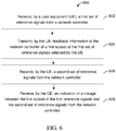
- FIGURE 6 illustrates an example method 600 for communicating in a wireless network.
- the method 600 could be performed by the UE 710.
- the method 600 comprises receiving, by a UE, a first set of reference signals from a network controller, at step 602.
- the UE 710 receives the first set of reference signals from the base station 770.
- the base station 770 sends a sequence of reference signals, each reference signal using different analog beamforming.
- the method 600 comprises transmitting, by the UE, feedback information to the network controller of a first subset of the first set of reference signals selected by the UE, at step 604.
- the UE 710 receives the first set of reference signals, determines which reference signals are the best ones, and sends a report back to the base station 770.
- the method 600 comprises receiving, by the UE, a second set of reference signals from the network controller at step 606, and receiving, by the UE, an indication of a linkage between the first subset of the first set of reference signals and the second set of reference signals from the network controller at step 608.
- the base station 770 uses the information about the best beams reported by the UE 710 to send the actual reference signals to the UE 710, and the UE 710 uses the best receive beams to receive those reference signals.
- the UE 710 may use the best beams to form a virtual MIMO channel to feed back the MIMO information (e.g., precoding, rank of transmission, and access level) to the base station 770, and then the base station 770 uses that to transmit data to be received by the UE 710.
- the base station 770 may form a set of reference signals based on the information received from the UE 710, the UE 710 uses the corresponding receive beam, and then the UE 710 determines the precoding, rank of transmission, and access level information, and feeds back again to the base station 770.
- FIGURE 7 illustrates an example communication system 700 that can implement transmission and reception of control and data channels with a group reference signal according to this disclosure.
- the system 700 enables multiple wireless users to transmit and receive data and other content.
- the system 700 may implement one or more channel access methods, such as code division multiple access (CDMA), time division multiple access (TDMA), frequency division multiple access (FDMA), orthogonal FDMA (OFDMA), or single-carrier FDMA (SC-FDMA).
- CDMA code division multiple access
- TDMA time division multiple access
- FDMA frequency division multiple access
- OFDMA orthogonal FDMA
- SC-FDMA single-carrier FDMA
- the communication system 700 includes user equipment (UE) 710a-710c, radio access networks (RANs) 720a-720b, a core network 730, a public switched telephone network (PSTN) 740, the Internet 750, and other networks 760. While certain numbers of these components or elements are shown in FIGURE 7 , any number of these components or elements may be included in the system 700.
- UE user equipment
- RANs radio access networks
- PSTN public switched telephone network
- the UEs 710a-710c are configured to operate and/or communicate in the system 700.
- the UEs 710a-710c are configured to transmit and/or receive wireless signals.
- Each UE 710a-710c represents any suitable end user device and may include such devices (or may be referred to) as a user equipment/device (UE), wireless transmit/receive unit (WTRU), mobile station, fixed or mobile subscriber unit, pager, cellular telephone, personal digital assistant (PDA), smartphone, laptop, computer, touchpad, wireless sensor, or consumer electronics device.
- UE user equipment/device
- WTRU wireless transmit/receive unit
- PDA personal digital assistant
- smartphone laptop, computer, touchpad, wireless sensor, or consumer electronics device.
- the RANs 720a-720b here include base stations 770a-770b, respectively.
- Each base station 770a-770b is configured to wirelessly interface with one or more of the UEs 710a-710c to enable access to the core network 730, the PSTN 740, the Internet 750, and/or the other networks 760.
- the base stations 770a-770b may include (or be) one or more of several well-known devices, such as a base transceiver station (BTS), a Node-B (NodeB), an evolved NodeB (eNodeB), a Home NodeB, a Home eNodeB, a site controller, an access point (AP), or a wireless router.
- BTS base transceiver station
- NodeB Node-B
- eNodeB evolved NodeB
- AP access point
- the base station 770a forms part of the RAN 720a, which may include other base stations, elements, and/or devices.
- the base station 770b forms part of the RAN 720b, which may include other base stations, elements, and/or devices.
- Each base station 770a-770b operates to transmit and/or receive wireless signals within a particular geographic region or area, sometimes referred to as a "cell.”
- MIMO multiple-input multiple-output
- the base stations 770a-770b communicate with one or more of the UEs 710a-710c over one or more air interfaces 790 using wireless communication links.
- the air interfaces 790 may utilize any suitable radio access technology.
- the system 700 may use multiple channel access functionality, including such schemes as described above.
- the base stations and UEs implement LTE, LTE-A, and/or LTE-B.
- LTE Long Term Evolution
- LTE-A Long Term Evolution
- LTE-B Long Term Evolution-B
- the RANs 720a-720b are in communication with the core network 730 to provide the UEs 710a-710c with voice, data, application, Voice over Internet Protocol (VoIP), or other services. Understandably, the RANs 720a-720b and/or the core network 730 may be in direct or indirect communication with one or more other RANs (not shown).
- the core network 730 may also serve as a gateway access for other networks (such as PSTN 740, Internet 750, and other networks 760).
- some or all of the UEs 710a-710c may include functionality for communicating with different wireless networks over different wireless links using different wireless technologies and/or protocols.
- FIGURE 7 illustrates one example of a communication system 700 that can implement transmission and reception of control and data channels with a group reference signal
- the communication system 700 could include any number of UEs, base stations, networks, or other components in any suitable configuration.
- FIGURES 8A and 8B illustrate example devices that can implement transmission and reception of control and data channels with a group reference signal according to this disclosure.
- FIGURE 8A illustrates an example UE 710
- FIGURE 8B illustrates an example base station 770. These components could be used in the system 700 or in any other suitable system.
- the UE 710 includes at least one processing unit 800.
- the processing unit 800 implements various processing operations of the UE 710.
- the processing unit 800 could perform signal coding, data processing, power control, input/output processing, or any other functionality enabling the UE 710 to operate in the system 700.
- the processing unit 800 also supports the receipt and use of control and data channels with a group reference signal as described in more detail below.
- Each processing unit 800 includes any suitable processing or computing device configured to perform one or more operations.
- Each processing unit 800 could, for example, include a microprocessor, microcontroller, digital signal processor, field programmable gate array, or application specific integrated circuit.
- the UE 710 also includes at least one transceiver 802.
- the transceiver 802 is configured to modulate data or other content for transmission by at least one antenna 804.
- the transceiver 802 is also configured to demodulate data or other content received by the at least one antenna 804.
- Each transceiver 802 includes any suitable structure for generating signals for wireless transmission and/or processing signals received wirelessly.
- Each antenna 804 includes any suitable structure for transmitting and/or receiving wireless signals.
- One or multiple transceivers 802 could be used in the UE 710, and one or multiple antennas 804 could be used in the UE 710. Although shown as a single functional unit, a transceiver 802 could also be implemented using at least one transmitter and at least one separate receiver.
- the UE 710 further includes one or more input/output devices 806.
- the input/output devices 806 facilitate interaction with a user.
- Each input/output device 806 includes any suitable structure for providing information to or receiving information from a user, such as a speaker, microphone, keypad, keyboard, display, or touch screen.
- the UE 710 includes at least one memory 808.
- the memory 808 stores instructions and data used, generated, or collected by the UE 710.
- the memory 808 could store software or firmware instructions executed by the processing unit(s) 800 and data used to reduce or eliminate interference in incoming signals.
- Each memory 808 includes any suitable volatile and/or non-volatile storage and retrieval device(s). Any suitable type of memory may be used, such as random access memory (RAM), read only memory (ROM), hard disk, optical disc, subscriber identity module (SIM) card, memory stick, secure digital (SD) memory card, and the like.
- the base station 770 includes at least one processing unit 850, at least one transmitter 852, at least one receiver 854, one or more antennas 856, at least one memory 858, and a network interface 860.
- the processing unit 850 implements various processing operations of the base station 770, such as signal coding, data processing, power control, input/output processing, or any other functionality.
- the processing unit 850 can also support the generation of signaling as described in more detail below.
- Each processing unit 850 includes any suitable processing or computing device configured to perform one or more operations.
- Each processing unit 850 could, for example, include a microprocessor, microcontroller, digital signal processor, field programmable gate array, or application specific integrated circuit.
- Each transmitter 852 includes any suitable structure for generating signals for wireless transmission to one or more UEs or other devices.
- Each receiver 854 includes any suitable structure for processing signals received wirelessly from one or more UEs or other devices. Although shown as separate components, at least one transmitter 852 and at least one receiver 854 could be combined into a transceiver.
- Each antenna 856 includes any suitable structure for transmitting and/or receiving wireless signals. While a common antenna 856 is shown here as being coupled to both the transmitter 852 and the receiver 854, one or more antennas 856 could be coupled to the transmitter(s) 852, and one or more separate antennas 856 could be coupled to the receiver(s) 854.
- Each memory 858 includes any suitable volatile and/or non-volatile storage and retrieval device(s).
- FIGURES 8A and 8B illustrate examples of such devices, various changes may be made to FIGURES 8A and 8B .
- each device 800, 850 could include any other or additional components according to particular needs.
- ROM read only memory
- RAM random access memory
- register cache memory
- semiconductor memory devices magnetic media such as internal hard disks and removable disks, magneto-optical media, and optical media such as CD-ROM disks, and digital versatile disks (DVDs).
- controller means any device, system or part thereof that controls at least one operation.
- a controller may be implemented in hardware, firmware, software, or some combination of at least two of the same. The functionality associated with any particular controller may be centralized or distributed, whether locally or remotely.
Claims (18)
- Verfahren zur drahtlosen Kommunikation, wobei das Verfahren umfasst:Senden (502) einer ersten Gruppe von Referenzsignalen durch eine Netzwerksteuerung zu einem Benutzer-Equipment, UE;Empfangen (504), durch die Netzwerksteuerung, von Rückmeldeinformation einer ersten Teilgruppe der ersten von dem UE ausgewählten Gruppe von Referenzsignalen durch das UE;Senden (506) einer zweiten Gruppe von Referenzsignalen durch die Netzwerksteuerung zum UE; undAngeben (508) einer ersten Verknüpfung zwischen der ersten Untergruppe der ersten Gruppe von Referenzsignalen und der zweiten Gruppe von Referenzsignalen durch die Netzwerksteuerung zum UE;wobei die erste Verknüpfung umfasst, dass gleiche Empfangsstrahlen am UE für die erste Untergruppe der ersten Gruppe von Referenzsignalen und die zweite Gruppe von Referenzsignalen verwendet werden.
- Verfahren nach Anspruch 1, ferner umfassend:Empfangen von zweiter Rückmeldeinformation zu einer zweiten Untergruppe der ersten von dem UE ausgewählten Gruppe von Referenzsignalen durch das UE;Senden einer dritten Gruppe von Referenzsignalen durch die Netzwerksteuerung zum UE; undAngeben einer zweiten Verknüpfung zwischen der zweiten Untergruppe der ersten Gruppe von Referenzsignalen und der dritten Gruppe von Referenzsignalen durch die Netzwerksteuerung zum UE.
- Verfahren nach Anspruch 1 oder Anspruch 2, wobei die gleichen Empfangsstrahlen am UE gleichen Antennenanschlüssen entsprechen.
- Verfahren nach Anspruch 3, wobei die Empfangsstrahlen am UE analoge Empfangsstrahlen umfassen.
- Verfahren nach einem der Ansprüche 1-4, wobei die erste Verknüpfung durch eine Konfigurationssignalisierung einer oberen Schicht, eine Downlink-Steuerungsinformation einer physikalischen Schicht oder eine Kombination aus beiden zum UE angegeben wird.
- Verfahren nach einem der Ansprüche 1-5, wobei jedes Referenzsignal der ersten Gruppe von Referenzsignalen unter Verwendung unterschiedlicher Strahlbildung gesendet wird.
- Verfahren nach einem der Ansprüche 1-6, wobei die Rückmeldeinformation von dem UE "Multiple Input Multiple Output"-, MIMO-, -Information umfasst, wobei die MIMO-Information eines oder mehrere von Vorcodierinformation, Rangangabe des Sendens, Kanalstatusinformation und Zugangsebeneninformation umfasst, basierend auf Messungen der ersten Untergruppe der ersten Gruppe von Referenzsignalen.
- Verfahren nach einem der Ansprüche 1-7, wobei die zweite Gruppe von Referenzsignalen ein erstes Referenzsignal und ein zweites Referenzsignal umfasst.
- Verfahren nach einem der Ansprüche 1-8, wobei eine Rückmeldung von Kanalstatusinformation basierend auf der ersten Gruppe von Referenzsignalen abgeleitet wird.
- Netzwerksteuerung in einem drahtlosen Netzwerk zum Kommunizieren mit einem Benutzer-Equipment (UE), umfassend Mittel zum Durchführen von einem der Verfahren nach Anspruch 1-9.
- Verfahren in einem Benutzer-Equipment, UE, zum Kommunizieren in einem drahtlosen Netzwerk, wobei das Verfahren umfasst:Empfangen (602) einer ersten Gruppe von Referenzsignalen von einer Netzwerksteuerung durch das UE;Senden (604) von Rückmeldeinformation zu der Netzwerksteuerung einer ersten Untergruppe der ersten von dem UE ausgewählten Gruppe von Referenzsignalen durch das UE;Empfangen (606) einer zweiten Gruppe von Referenzsignalen von der Netzwerksteuerung durch das UE; undEmpfangen (608) einer Angabe einer ersten Verknüpfung zwischen der ersten Untergruppe der ersten Gruppe von Referenzsignalen und der zweiten Gruppe von Referenzsignalen von der Netzwerksteuerung durch das UE;wobei die erste Verknüpfung umfasst, dass gleiche Empfangsstrahlen am UE für die erste Untergruppe der ersten Gruppe von Referenzsignalen und die zweite Gruppe von Referenzsignalen verwendet werden.
- Verfahren nach Anspruch 11, ferner umfassend:Senden von zweiter Rückmeldeinformation durch das UE zu der Netzwerksteuerung einer zweiten Untergruppe der ersten durch das UE ausgewählten Gruppe von Referenzsignalen;Empfangen einer dritten Gruppe von Referenzsignalen von der Netzwerksteuerung durch das UE; undEmpfangen einer Angabe einer zweiten Verknüpfung zwischen der zweiten Untergruppe der ersten Gruppe von Referenzsignalen und der dritten Gruppe von Referenzsignalen durch das UE.
- Verfahren nach Anspruch 11 oder 12, wobei die gleichen Empfangsstrahlen an dem UE gleichen Antennenanschlüssen entsprechen.
- Verfahren nach einem der Ansprüche 11-13, wobei die zweite Gruppe von Referenzsignalen ein erstes Referenzsignal und ein zweites Referenzsignal umfasst, wobei das erste Referenzsignal und das zweite Referenzsignal ein erstes Gruppenreferenzsignal, GRS, umfassen.
- Verfahren nach Anspruch 14, wobei das erste GRS in einem Rahmen empfangen wird, umfassend eine Steuerungsregion, die dem ersten GRS zum Senden von Downlink-Steuerungsinformation, DCI, entspricht.
- Verfahren nach einem der Ansprüche 11-15, wobei eine Angabe der ersten Verknüpfung von dem UE durch eine Konfigurationssignalisierung einer oberen Schicht, eine Downlink-Steuerungsinformation einer physikalischen Schicht oder eine Kombination aus beiden empfangen wird.
- Verfahren nach einem der Ansprüche 11-16, wobei Rückmeldung zur Kanalstatusinformationen basierend auf der ersten Gruppe von Referenzsignalen abgeleitet wird.
- Benutzer-Equipment, UE, zum Kommunizieren in einem drahtlosen Netzwerk, umfassend Mittel zum Durchführen von einem der Verfahren nach Anspruch 11-17.
Priority Applications (1)
| Application Number | Priority Date | Filing Date | Title |
|---|---|---|---|
| EP19217796.2A EP3661302A1 (de) | 2015-12-18 | 2016-12-17 | System und verfahren zum senden und empfangen von steuerungs- und datenkanälen mit gruppenreferenzsignal |
Applications Claiming Priority (2)
| Application Number | Priority Date | Filing Date | Title |
|---|---|---|---|
| US14/975,256 US10187880B2 (en) | 2015-12-18 | 2015-12-18 | System and method for transmission and reception of control and data channels with group reference signal |
| PCT/CN2016/110564 WO2017101876A1 (en) | 2015-12-18 | 2016-12-17 | System and method for transmission and reception of control and data channels with group reference signal |
Related Child Applications (2)
| Application Number | Title | Priority Date | Filing Date |
|---|---|---|---|
| EP19217796.2A Division-Into EP3661302A1 (de) | 2015-12-18 | 2016-12-17 | System und verfahren zum senden und empfangen von steuerungs- und datenkanälen mit gruppenreferenzsignal |
| EP19217796.2A Division EP3661302A1 (de) | 2015-12-18 | 2016-12-17 | System und verfahren zum senden und empfangen von steuerungs- und datenkanälen mit gruppenreferenzsignal |
Publications (3)
| Publication Number | Publication Date |
|---|---|
| EP3375238A1 EP3375238A1 (de) | 2018-09-19 |
| EP3375238A4 EP3375238A4 (de) | 2018-12-05 |
| EP3375238B1 true EP3375238B1 (de) | 2020-02-12 |
Family
ID=59055783
Family Applications (2)
| Application Number | Title | Priority Date | Filing Date |
|---|---|---|---|
| EP16874933.1A Active EP3375238B1 (de) | 2015-12-18 | 2016-12-17 | System und verfahren zum senden und empfangen von steuer- und datenkanälen mit gruppenreferenzsignal |
| EP19217796.2A Pending EP3661302A1 (de) | 2015-12-18 | 2016-12-17 | System und verfahren zum senden und empfangen von steuerungs- und datenkanälen mit gruppenreferenzsignal |
Family Applications After (1)
| Application Number | Title | Priority Date | Filing Date |
|---|---|---|---|
| EP19217796.2A Pending EP3661302A1 (de) | 2015-12-18 | 2016-12-17 | System und verfahren zum senden und empfangen von steuerungs- und datenkanälen mit gruppenreferenzsignal |
Country Status (5)
| Country | Link |
|---|---|
| US (2) | US10187880B2 (de) |
| EP (2) | EP3375238B1 (de) |
| CN (2) | CN108293251B (de) |
| ES (1) | ES2783862T3 (de) |
| WO (1) | WO2017101876A1 (de) |
Families Citing this family (18)
| Publication number | Priority date | Publication date | Assignee | Title |
|---|---|---|---|---|
| EP3398282B1 (de) * | 2015-12-31 | 2022-02-23 | IDAC Holdings, Inc. | Verfahren zur dynamischen verwaltung von referenzsignalen |
| US11038557B2 (en) * | 2016-03-31 | 2021-06-15 | Samsung Electronics Co., Ltd. | Method and apparatus for transmitting and receiving reference signals in wireless communication |
| WO2018016921A1 (ko) * | 2016-07-21 | 2018-01-25 | 엘지전자 주식회사 | 무선 통신 시스템에서 기지국과 단말 간 하향링크 제어 정보를 송수신하는 방법 및 이를 지원하는 장치 |
| CN109690969A (zh) * | 2016-07-29 | 2019-04-26 | Lg电子株式会社 | 在无线通信系统中由终端报告信道状态信息的方法以及支持该方法的装置 |
| WO2018064399A1 (en) * | 2016-09-28 | 2018-04-05 | Ntt Docomo, Inc. | Wireless communication method |
| WO2018065662A1 (en) * | 2016-10-03 | 2018-04-12 | Nokia Technologies Oy | Reference signal with beamforming training and channel estimation |
| WO2018143595A1 (ko) * | 2017-02-02 | 2018-08-09 | 엘지전자 주식회사 | 분산 안테나 통신 시스템에서 기지국과 차량 단말 간 신호 송수신 방법 및 이를 위한 장치 |
| RU2757809C2 (ru) | 2017-03-27 | 2021-10-21 | Идак Холдингз, Инк. | Адаптивные конфигурации кодовой книги цифрового прекодера для связи в диапазоне миллиметровых волн на основе гибридного формирования луча |
| CN109302220B (zh) * | 2017-07-25 | 2021-12-28 | 华为技术有限公司 | 用于数据传输的方法、装置和系统 |
| CN109495149B (zh) | 2017-09-11 | 2021-10-15 | 华为技术有限公司 | 通信方法、网络设备、终端设备和系统 |
| US10123322B1 (en) | 2017-09-18 | 2018-11-06 | Qualcomm Incorporated | Transmission of beam switch commands through control channel signaling |
| CN109803286B (zh) * | 2017-11-17 | 2022-04-29 | 北京紫光展锐通信技术有限公司 | 波束失败后的处理方法、装置及终端 |
| WO2019143688A1 (en) | 2018-01-19 | 2019-07-25 | Pcms Holdings, Inc. | Multi-focal planes with varying positions |
| WO2019183211A1 (en) | 2018-03-23 | 2019-09-26 | Pcms Holdings, Inc. | Multifocal plane based method to produce stereoscopic viewpoints in a dibr system (mfp-dibr) |
| EP3818694A1 (de) | 2018-07-05 | 2021-05-12 | PCMS Holdings, Inc. | Vorrichtung und verfahren für augennahe fokalebenenüberlagerungen für 3d-wahrnehmung von inhalt auf 2d-anzeigen |
| US11228346B2 (en) * | 2019-10-03 | 2022-01-18 | Qualcomm Incorporated | Beam capability enhancements using multiple receive ports |
| CN116866979A (zh) * | 2021-03-31 | 2023-10-10 | 北京小米移动软件有限公司 | 波束恢复方法、装置、用户设备、网络侧设备及存储介质 |
| US20230039254A1 (en) * | 2021-08-03 | 2023-02-09 | Qualcomm Incorporated | Transfer/federated learning approaches to mitigate blockage in millimeter wave systems |
Family Cites Families (23)
| Publication number | Priority date | Publication date | Assignee | Title |
|---|---|---|---|---|
| US20020136276A1 (en) | 2000-03-09 | 2002-09-26 | Franceschini Michael R. | Frequency domain direct sequence spread spectrum with flexible time frequency code |
| US8116278B2 (en) | 2008-08-20 | 2012-02-14 | Nokia Siemens Networks Oy | Spectrum sharing between OFDM and non-OFDM radios |
| US8676133B2 (en) * | 2008-09-19 | 2014-03-18 | Qualcomm Incorporated | Reference signal design for LTE A |
| US8660598B2 (en) * | 2009-11-06 | 2014-02-25 | Nec Laboratories America, Inc. | Systems and methods for prioritizing beams to enable efficient determination of suitable communication links |
| US8385302B2 (en) | 2009-11-20 | 2013-02-26 | Qualcomm Incorporated | Methods and apparatus for enabling distributed beacon transmissions |
| US10638464B2 (en) * | 2011-04-01 | 2020-04-28 | Futurewei Technologies, Inc. | System and method for transmission and reception of control channels in a communications system |
| US9544790B2 (en) * | 2011-06-28 | 2017-01-10 | Lg Electronics Inc. | Method for monitoring downlink control information (DCI) and a user equipment using the same |
| US20130039291A1 (en) * | 2011-08-12 | 2013-02-14 | Research In Motion Limited | Design on Enhanced Control Channel for Wireless System |
| US9252918B2 (en) * | 2011-08-15 | 2016-02-02 | Google Technology Holdings LLC | Method and apparatus for control channel transmission and reception |
| US8971881B2 (en) * | 2012-03-23 | 2015-03-03 | Google Technology Holdings LLC | Radio link monitoring in a wireless communication device for an enhanced control channel |
| KR20130127347A (ko) * | 2012-05-10 | 2013-11-22 | 삼성전자주식회사 | 아날로그 및 디지털 하이브리드 빔포밍을 통한 통신 방법 및 장치 |
| US9439096B2 (en) * | 2012-08-13 | 2016-09-06 | Samsung Electronics Co., Ltd. | Method and apparatus to support channel refinement and multi-stream transmission in millimeter wave systems |
| EP2930992B1 (de) * | 2012-12-07 | 2022-08-10 | LG Electronics Inc. | Verfahren und vorrichtung zum übertragen und empfangen von steuersignalen |
| US8976884B2 (en) | 2012-12-20 | 2015-03-10 | Google Technology Holdings LLC | Method and apparatus for antenna array channel feedback |
| KR102043021B1 (ko) * | 2013-04-15 | 2019-11-12 | 삼성전자주식회사 | 이동 통신 시스템에서 빔포밍을 위한 스케쥴링 방법 및 장치 |
| KR102079629B1 (ko) * | 2013-05-02 | 2020-02-21 | 삼성전자주식회사 | 무선 통신 시스템에서 하이브리드 빔포밍의 복잡도 개선을 위한 방법 및 장치 |
| US20150103934A1 (en) * | 2013-10-16 | 2015-04-16 | Electronics And Telecommunications Research Institute | Method and apparatus for communication in millimeter wave mimo communication environment |
| US9832629B2 (en) | 2014-01-28 | 2017-11-28 | Qualcomm Incorporated | Discovery signals and network synchronization signals design in LTE |
| WO2015137636A2 (en) * | 2014-03-13 | 2015-09-17 | Lg Electronics Inc. | Method of feedback for beamforming in a wireless communication system and apparatus therefor |
| US20170070979A1 (en) * | 2014-03-21 | 2017-03-09 | Telefonaktiebolaget Lm Ericsson (Publ) | Adaptive outer loop for physical downlink channel link adaptation |
| CN105007126B (zh) * | 2014-04-23 | 2017-09-29 | 电信科学技术研究院 | 一种信道状态信息测量的方法、系统及设备 |
| EP3165038B1 (de) * | 2014-07-03 | 2020-08-19 | LG Electronics Inc. | Verfahren und vorrichtung zur übertragung von uplink-daten in einem drahtloskommunikationssystem |
| US10014918B2 (en) * | 2015-09-12 | 2018-07-03 | Telefonaktiebolaget Lm Ericsson (Publ) | Systems and methods for beam selection for hybrid beamforming |
-
2015
- 2015-12-18 US US14/975,256 patent/US10187880B2/en active Active
-
2016
- 2016-12-17 EP EP16874933.1A patent/EP3375238B1/de active Active
- 2016-12-17 EP EP19217796.2A patent/EP3661302A1/de active Pending
- 2016-12-17 CN CN201680070191.6A patent/CN108293251B/zh active Active
- 2016-12-17 ES ES16874933T patent/ES2783862T3/es active Active
- 2016-12-17 CN CN202110313493.4A patent/CN113193942A/zh active Pending
- 2016-12-17 WO PCT/CN2016/110564 patent/WO2017101876A1/en active Application Filing
-
2018
- 2018-11-13 US US16/189,693 patent/US10757696B2/en active Active
Non-Patent Citations (1)
| Title |
|---|
| None * |
Also Published As
| Publication number | Publication date |
|---|---|
| CN113193942A (zh) | 2021-07-30 |
| EP3375238A1 (de) | 2018-09-19 |
| ES2783862T3 (es) | 2020-09-18 |
| US20190082429A1 (en) | 2019-03-14 |
| US10187880B2 (en) | 2019-01-22 |
| US20170181132A1 (en) | 2017-06-22 |
| EP3661302A1 (de) | 2020-06-03 |
| US10757696B2 (en) | 2020-08-25 |
| WO2017101876A1 (en) | 2017-06-22 |
| EP3375238A4 (de) | 2018-12-05 |
| CN108293251A (zh) | 2018-07-17 |
| CN108293251B (zh) | 2021-03-30 |
Similar Documents
| Publication | Publication Date | Title |
|---|---|---|
| US10757696B2 (en) | System and method for transmission and reception of control and data channels with group reference signal | |
| US20200329392A1 (en) | Method and apparatus for measurement reference signal | |
| CN110249574B (zh) | 在无线通信系统中测量并报告信道状态信息的方法及其装置 | |
| CN110476391B (zh) | 在无线通信系统中报告信道状态信息的方法及其设备 | |
| CN110098853B (zh) | 用于协作多点传输的速率匹配和干扰测量资源的配置 | |
| KR101988285B1 (ko) | 무선 통신 시스템에서 채널 상태 정보 송수신 방법 및 장치 | |
| EP3105875B1 (de) | Kopplung von referenzsignalen in einem drahtlosen netzwerk | |
| US10911166B2 (en) | Method and apparatus for measuring channel in wireless communication system | |
| US8976770B2 (en) | Method and device whereby base station allocates nodes to terminal in a semi-static fashion in multi-node system | |
| US10720973B2 (en) | Method for ultra-high frequency mobile communication system transreceiving reference signal and feedback and apparatus for same | |
| JP5993238B2 (ja) | 通信システム、基地局装置、端末装置、及び通信方法 | |
| US20130250879A1 (en) | Method and apparatus for transmission mode design for extension carrier of lte advanced | |
| US11937282B2 (en) | Method and apparatus for beam management for mobility | |
| WO2015154283A1 (zh) | 一种报告信道状态信息的方法、用户设备和基站 | |
| WO2014193070A1 (en) | Reference signals extension for massive mimo system | |
| MX2015003270A (es) | Metodo y aparato para recibir datos en sistema de comunicacion inalambrica que soporta transmision cooperativa. | |
| KR20140036923A (ko) | 무선 통신 시스템에서 채널 상태 정보 송수신 방법 및 장치 | |
| KR20180021201A (ko) | 이동 통신 시스템에서 채널을 측정하는 방법 및 장치 | |
| CN116318587A (zh) | 多个无线电接入技术共存场景中的共享信道重映射 | |
| WO2019140389A1 (en) | User equipment and wireless communication method | |
| US20160365957A1 (en) | Wireless communication system, method for transmitting information of user equipment, method for receiving information of base station, and user equipment and base station thereof | |
| US11140683B2 (en) | Methods and apparatuses for periodic uplink signals with hybrid transceiver architectures | |
| KR20170123577A (ko) | 다양한 빔 관리 방법을 적용하는 이동통신 시스템의 신호 송수신 방법 및 그 장치 | |
| JP2020505880A (ja) | ユーザ端末及び無線通信方法 | |
| KR20180002129A (ko) | 초고주파 이동통신 시스템의 분산 안테나를 통한 데이터 송수신 방법 및 장치 |
Legal Events
| Date | Code | Title | Description |
|---|---|---|---|
| STAA | Information on the status of an ep patent application or granted ep patent |
Free format text: STATUS: THE INTERNATIONAL PUBLICATION HAS BEEN MADE |
|
| PUAI | Public reference made under article 153(3) epc to a published international application that has entered the european phase |
Free format text: ORIGINAL CODE: 0009012 |
|
| STAA | Information on the status of an ep patent application or granted ep patent |
Free format text: STATUS: REQUEST FOR EXAMINATION WAS MADE |
|
| 17P | Request for examination filed |
Effective date: 20180613 |
|
| AK | Designated contracting states |
Kind code of ref document: A1 Designated state(s): AL AT BE BG CH CY CZ DE DK EE ES FI FR GB GR HR HU IE IS IT LI LT LU LV MC MK MT NL NO PL PT RO RS SE SI SK SM TR |
|
| AX | Request for extension of the european patent |
Extension state: BA ME |
|
| A4 | Supplementary search report drawn up and despatched |
Effective date: 20181107 |
|
| RIC1 | Information provided on ipc code assigned before grant |
Ipc: H04W 72/04 20090101AFI20181031BHEP Ipc: H04B 7/06 20060101ALI20181031BHEP Ipc: H04B 7/08 20060101ALI20181031BHEP Ipc: H04W 72/08 20090101ALI20181031BHEP Ipc: H04L 27/26 20060101ALI20181031BHEP |
|
| DAV | Request for validation of the european patent (deleted) | ||
| DAX | Request for extension of the european patent (deleted) | ||
| GRAP | Despatch of communication of intention to grant a patent |
Free format text: ORIGINAL CODE: EPIDOSNIGR1 |
|
| STAA | Information on the status of an ep patent application or granted ep patent |
Free format text: STATUS: GRANT OF PATENT IS INTENDED |
|
| INTG | Intention to grant announced |
Effective date: 20190812 |
|
| GRAS | Grant fee paid |
Free format text: ORIGINAL CODE: EPIDOSNIGR3 |
|
| GRAA | (expected) grant |
Free format text: ORIGINAL CODE: 0009210 |
|
| STAA | Information on the status of an ep patent application or granted ep patent |
Free format text: STATUS: THE PATENT HAS BEEN GRANTED |
|
| AK | Designated contracting states |
Kind code of ref document: B1 Designated state(s): AL AT BE BG CH CY CZ DE DK EE ES FI FR GB GR HR HU IE IS IT LI LT LU LV MC MK MT NL NO PL PT RO RS SE SI SK SM TR |
|
| REG | Reference to a national code |
Ref country code: GB Ref legal event code: FG4D |
|
| REG | Reference to a national code |
Ref country code: CH Ref legal event code: EP |
|
| REG | Reference to a national code |
Ref country code: AT Ref legal event code: REF Ref document number: 1233819 Country of ref document: AT Kind code of ref document: T Effective date: 20200215 |
|
| REG | Reference to a national code |
Ref country code: IE Ref legal event code: FG4D |
|
| REG | Reference to a national code |
Ref country code: DE Ref legal event code: R096 Ref document number: 602016029842 Country of ref document: DE |
|
| PG25 | Lapsed in a contracting state [announced via postgrant information from national office to epo] |
Ref country code: NO Free format text: LAPSE BECAUSE OF FAILURE TO SUBMIT A TRANSLATION OF THE DESCRIPTION OR TO PAY THE FEE WITHIN THE PRESCRIBED TIME-LIMIT Effective date: 20200512 Ref country code: FI Free format text: LAPSE BECAUSE OF FAILURE TO SUBMIT A TRANSLATION OF THE DESCRIPTION OR TO PAY THE FEE WITHIN THE PRESCRIBED TIME-LIMIT Effective date: 20200212 Ref country code: RS Free format text: LAPSE BECAUSE OF FAILURE TO SUBMIT A TRANSLATION OF THE DESCRIPTION OR TO PAY THE FEE WITHIN THE PRESCRIBED TIME-LIMIT Effective date: 20200212 |
|
| REG | Reference to a national code |
Ref country code: LT Ref legal event code: MG4D |
|
| REG | Reference to a national code |
Ref country code: NL Ref legal event code: MP Effective date: 20200212 |
|
| PG25 | Lapsed in a contracting state [announced via postgrant information from national office to epo] |
Ref country code: BG Free format text: LAPSE BECAUSE OF FAILURE TO SUBMIT A TRANSLATION OF THE DESCRIPTION OR TO PAY THE FEE WITHIN THE PRESCRIBED TIME-LIMIT Effective date: 20200512 Ref country code: IS Free format text: LAPSE BECAUSE OF FAILURE TO SUBMIT A TRANSLATION OF THE DESCRIPTION OR TO PAY THE FEE WITHIN THE PRESCRIBED TIME-LIMIT Effective date: 20200612 Ref country code: GR Free format text: LAPSE BECAUSE OF FAILURE TO SUBMIT A TRANSLATION OF THE DESCRIPTION OR TO PAY THE FEE WITHIN THE PRESCRIBED TIME-LIMIT Effective date: 20200513 Ref country code: HR Free format text: LAPSE BECAUSE OF FAILURE TO SUBMIT A TRANSLATION OF THE DESCRIPTION OR TO PAY THE FEE WITHIN THE PRESCRIBED TIME-LIMIT Effective date: 20200212 Ref country code: LV Free format text: LAPSE BECAUSE OF FAILURE TO SUBMIT A TRANSLATION OF THE DESCRIPTION OR TO PAY THE FEE WITHIN THE PRESCRIBED TIME-LIMIT Effective date: 20200212 Ref country code: SE Free format text: LAPSE BECAUSE OF FAILURE TO SUBMIT A TRANSLATION OF THE DESCRIPTION OR TO PAY THE FEE WITHIN THE PRESCRIBED TIME-LIMIT Effective date: 20200212 |
|
| REG | Reference to a national code |
Ref country code: ES Ref legal event code: FG2A Ref document number: 2783862 Country of ref document: ES Kind code of ref document: T3 Effective date: 20200918 |
|
| PG25 | Lapsed in a contracting state [announced via postgrant information from national office to epo] |
Ref country code: NL Free format text: LAPSE BECAUSE OF FAILURE TO SUBMIT A TRANSLATION OF THE DESCRIPTION OR TO PAY THE FEE WITHIN THE PRESCRIBED TIME-LIMIT Effective date: 20200212 |
|
| REG | Reference to a national code |
Ref country code: AT Ref legal event code: UEP Ref document number: 1233819 Country of ref document: AT Kind code of ref document: T Effective date: 20200212 |
|
| PG25 | Lapsed in a contracting state [announced via postgrant information from national office to epo] |
Ref country code: SM Free format text: LAPSE BECAUSE OF FAILURE TO SUBMIT A TRANSLATION OF THE DESCRIPTION OR TO PAY THE FEE WITHIN THE PRESCRIBED TIME-LIMIT Effective date: 20200212 Ref country code: DK Free format text: LAPSE BECAUSE OF FAILURE TO SUBMIT A TRANSLATION OF THE DESCRIPTION OR TO PAY THE FEE WITHIN THE PRESCRIBED TIME-LIMIT Effective date: 20200212 Ref country code: EE Free format text: LAPSE BECAUSE OF FAILURE TO SUBMIT A TRANSLATION OF THE DESCRIPTION OR TO PAY THE FEE WITHIN THE PRESCRIBED TIME-LIMIT Effective date: 20200212 Ref country code: PT Free format text: LAPSE BECAUSE OF FAILURE TO SUBMIT A TRANSLATION OF THE DESCRIPTION OR TO PAY THE FEE WITHIN THE PRESCRIBED TIME-LIMIT Effective date: 20200705 Ref country code: LT Free format text: LAPSE BECAUSE OF FAILURE TO SUBMIT A TRANSLATION OF THE DESCRIPTION OR TO PAY THE FEE WITHIN THE PRESCRIBED TIME-LIMIT Effective date: 20200212 Ref country code: RO Free format text: LAPSE BECAUSE OF FAILURE TO SUBMIT A TRANSLATION OF THE DESCRIPTION OR TO PAY THE FEE WITHIN THE PRESCRIBED TIME-LIMIT Effective date: 20200212 Ref country code: CZ Free format text: LAPSE BECAUSE OF FAILURE TO SUBMIT A TRANSLATION OF THE DESCRIPTION OR TO PAY THE FEE WITHIN THE PRESCRIBED TIME-LIMIT Effective date: 20200212 Ref country code: SK Free format text: LAPSE BECAUSE OF FAILURE TO SUBMIT A TRANSLATION OF THE DESCRIPTION OR TO PAY THE FEE WITHIN THE PRESCRIBED TIME-LIMIT Effective date: 20200212 |
|
| REG | Reference to a national code |
Ref country code: DE Ref legal event code: R097 Ref document number: 602016029842 Country of ref document: DE |
|
| PLBE | No opposition filed within time limit |
Free format text: ORIGINAL CODE: 0009261 |
|
| STAA | Information on the status of an ep patent application or granted ep patent |
Free format text: STATUS: NO OPPOSITION FILED WITHIN TIME LIMIT |
|
| 26N | No opposition filed |
Effective date: 20201113 |
|
| PG25 | Lapsed in a contracting state [announced via postgrant information from national office to epo] |
Ref country code: IT Free format text: LAPSE BECAUSE OF FAILURE TO SUBMIT A TRANSLATION OF THE DESCRIPTION OR TO PAY THE FEE WITHIN THE PRESCRIBED TIME-LIMIT Effective date: 20200212 |
|
| PG25 | Lapsed in a contracting state [announced via postgrant information from national office to epo] |
Ref country code: PL Free format text: LAPSE BECAUSE OF FAILURE TO SUBMIT A TRANSLATION OF THE DESCRIPTION OR TO PAY THE FEE WITHIN THE PRESCRIBED TIME-LIMIT Effective date: 20200212 Ref country code: SI Free format text: LAPSE BECAUSE OF FAILURE TO SUBMIT A TRANSLATION OF THE DESCRIPTION OR TO PAY THE FEE WITHIN THE PRESCRIBED TIME-LIMIT Effective date: 20200212 |
|
| REG | Reference to a national code |
Ref country code: CH Ref legal event code: PL |
|
| GBPC | Gb: european patent ceased through non-payment of renewal fee |
Effective date: 20201217 |
|
| PG25 | Lapsed in a contracting state [announced via postgrant information from national office to epo] |
Ref country code: MC Free format text: LAPSE BECAUSE OF FAILURE TO SUBMIT A TRANSLATION OF THE DESCRIPTION OR TO PAY THE FEE WITHIN THE PRESCRIBED TIME-LIMIT Effective date: 20200212 |
|
| REG | Reference to a national code |
Ref country code: BE Ref legal event code: MM Effective date: 20201231 |
|
| PG25 | Lapsed in a contracting state [announced via postgrant information from national office to epo] |
Ref country code: IE Free format text: LAPSE BECAUSE OF NON-PAYMENT OF DUE FEES Effective date: 20201217 Ref country code: FR Free format text: LAPSE BECAUSE OF NON-PAYMENT OF DUE FEES Effective date: 20201231 Ref country code: LU Free format text: LAPSE BECAUSE OF NON-PAYMENT OF DUE FEES Effective date: 20201217 |
|
| PG25 | Lapsed in a contracting state [announced via postgrant information from national office to epo] |
Ref country code: CH Free format text: LAPSE BECAUSE OF NON-PAYMENT OF DUE FEES Effective date: 20201231 Ref country code: LI Free format text: LAPSE BECAUSE OF NON-PAYMENT OF DUE FEES Effective date: 20201231 Ref country code: GB Free format text: LAPSE BECAUSE OF NON-PAYMENT OF DUE FEES Effective date: 20201217 |
|
| PG25 | Lapsed in a contracting state [announced via postgrant information from national office to epo] |
Ref country code: MT Free format text: LAPSE BECAUSE OF FAILURE TO SUBMIT A TRANSLATION OF THE DESCRIPTION OR TO PAY THE FEE WITHIN THE PRESCRIBED TIME-LIMIT Effective date: 20200212 Ref country code: CY Free format text: LAPSE BECAUSE OF FAILURE TO SUBMIT A TRANSLATION OF THE DESCRIPTION OR TO PAY THE FEE WITHIN THE PRESCRIBED TIME-LIMIT Effective date: 20200212 |
|
| PG25 | Lapsed in a contracting state [announced via postgrant information from national office to epo] |
Ref country code: MK Free format text: LAPSE BECAUSE OF FAILURE TO SUBMIT A TRANSLATION OF THE DESCRIPTION OR TO PAY THE FEE WITHIN THE PRESCRIBED TIME-LIMIT Effective date: 20200212 Ref country code: AL Free format text: LAPSE BECAUSE OF FAILURE TO SUBMIT A TRANSLATION OF THE DESCRIPTION OR TO PAY THE FEE WITHIN THE PRESCRIBED TIME-LIMIT Effective date: 20200212 |
|
| PG25 | Lapsed in a contracting state [announced via postgrant information from national office to epo] |
Ref country code: BE Free format text: LAPSE BECAUSE OF NON-PAYMENT OF DUE FEES Effective date: 20201231 |
|
| PGFP | Annual fee paid to national office [announced via postgrant information from national office to epo] |
Ref country code: TR Payment date: 20221216 Year of fee payment: 7 Ref country code: ES Payment date: 20230112 Year of fee payment: 7 |
|
| P01 | Opt-out of the competence of the unified patent court (upc) registered |
Effective date: 20230514 |
|
| PGFP | Annual fee paid to national office [announced via postgrant information from national office to epo] |
Ref country code: DE Payment date: 20231031 Year of fee payment: 8 Ref country code: AT Payment date: 20231127 Year of fee payment: 8 |
|
| PGFP | Annual fee paid to national office [announced via postgrant information from national office to epo] |
Ref country code: ES Payment date: 20240118 Year of fee payment: 8 |