EP3374969B1 - Modelling complex geological sequences using geologic rules and paleographic maps - Google Patents
Modelling complex geological sequences using geologic rules and paleographic maps Download PDFInfo
- Publication number
- EP3374969B1 EP3374969B1 EP15908407.8A EP15908407A EP3374969B1 EP 3374969 B1 EP3374969 B1 EP 3374969B1 EP 15908407 A EP15908407 A EP 15908407A EP 3374969 B1 EP3374969 B1 EP 3374969B1
- Authority
- EP
- European Patent Office
- Prior art keywords
- interval
- mrs
- gross
- thickness
- actual top
- Prior art date
- Legal status (The legal status is an assumption and is not a legal conclusion. Google has not performed a legal analysis and makes no representation as to the accuracy of the status listed.)
- Active
Links
- 238000000034 method Methods 0.000 claims description 39
- 208000035126 Facies Diseases 0.000 claims description 33
- 230000008021 deposition Effects 0.000 claims description 2
- 238000010586 diagram Methods 0.000 description 15
- 230000006870 function Effects 0.000 description 6
- 238000012545 processing Methods 0.000 description 5
- 230000003287 optical effect Effects 0.000 description 3
- 238000013459 approach Methods 0.000 description 2
- 238000004891 communication Methods 0.000 description 2
- 238000007796 conventional method Methods 0.000 description 2
- 230000002093 peripheral effect Effects 0.000 description 2
- 239000007787 solid Substances 0.000 description 2
- 230000002730 additional effect Effects 0.000 description 1
- 238000003491 array Methods 0.000 description 1
- 230000007812 deficiency Effects 0.000 description 1
- 238000005553 drilling Methods 0.000 description 1
- 238000005516 engineering process Methods 0.000 description 1
- 239000000284 extract Substances 0.000 description 1
- 230000005055 memory storage Effects 0.000 description 1
- 238000012986 modification Methods 0.000 description 1
- 230000004048 modification Effects 0.000 description 1
- 239000013307 optical fiber Substances 0.000 description 1
- 230000001373 regressive effect Effects 0.000 description 1
- 230000004044 response Effects 0.000 description 1
- 239000011435 rock Substances 0.000 description 1
- 239000004065 semiconductor Substances 0.000 description 1
- 230000008719 thickening Effects 0.000 description 1
- 238000012546 transfer Methods 0.000 description 1
- 230000007704 transition Effects 0.000 description 1
- XLYOFNOQVPJJNP-UHFFFAOYSA-N water Substances O XLYOFNOQVPJJNP-UHFFFAOYSA-N 0.000 description 1
Images


Classifications
-
- G01V20/00—
-
- G—PHYSICS
- G01—MEASURING; TESTING
- G01V—GEOPHYSICS; GRAVITATIONAL MEASUREMENTS; DETECTING MASSES OR OBJECTS; TAGS
- G01V1/00—Seismology; Seismic or acoustic prospecting or detecting
- G01V1/28—Processing seismic data, e.g. analysis, for interpretation, for correction
- G01V1/30—Analysis
- G01V1/301—Analysis for determining seismic cross-sections or geostructures
- G01V1/302—Analysis for determining seismic cross-sections or geostructures in 3D data cubes
-
- G—PHYSICS
- G06—COMPUTING; CALCULATING OR COUNTING
- G06F—ELECTRIC DIGITAL DATA PROCESSING
- G06F30/00—Computer-aided design [CAD]
- G06F30/20—Design optimisation, verification or simulation
-
- G—PHYSICS
- G01—MEASURING; TESTING
- G01V—GEOPHYSICS; GRAVITATIONAL MEASUREMENTS; DETECTING MASSES OR OBJECTS; TAGS
- G01V2210/00—Details of seismic processing or analysis
- G01V2210/60—Analysis
- G01V2210/64—Geostructures, e.g. in 3D data cubes
Definitions
- the present disclosure generally relates to systems and methods for modelling complex geological sequences using geologic rules and paleographic maps. More particularly, the present disclosure relates to modelling complex geological sequences representing new actual surfaces within a gross interval thickness using geologic rules based on facies data and paleographic maps represented by MRS shoreline facies.
- Modelling complex geological sequences may utilize conventional techniques such as, for example, proportional layering to create stratigraphic subdivisions between grids that represent a more detailed layering of the earth.
- This technique assumes a parallel and conformable geometric pattern for a gross interval thickness, which is the difference between two gridded surfaces.
- the gross interval thickness may be appropriate for certain portions of an overall depositional sequence (i.e., the top-set and bottom-set portions), but is inappropriate for the pro-grading, clinoform-dominated portions of the depositional sequence.
- Another conventional technique for modelling complex geological sequences uses proportions and flattens all stratigraphic layers in geologic time in an attempt to restore the subsurface model into a chronostratigraphic model. In doing this, a mathematical technique is applied for proportional layering across the subsurface model. This type of proportional layering technique has limited use when the goal is to model the entire depositional sequence (i.e., for areas with pro-gradational clinoforms that cannot be modeled using conventional approaches to proportional layering).
- 3D subsurface models that can be translated into a chronostratigraphic model.
- the 3D subsurface model is created by direct interpretation of seismic data.
- the 3D subsurface model is derived directly from densely sampled seismic data.
- This technique extracts time-stratigraphic surfaces from seismic data (using coherence attributes) to build a time-stratigraphic 3D subsurface model.
- the constructed 3D subsurface model is translated into a chronostratigraphic model.
- This approach can work when available seismic data has a high signal-to-noise ratio. However, in regions of poor quality seismic data, building with this technique is impossible.
- GB2512372 A discloses a method of modelling a subsurface volume.
- the method comprises defining a regular planar grid of regularly arranged locations in the two dimensions substantially parallel to the surface and calculating a plurality of one dimensional arrays, each extending from a different one of the regularly arranged locations.
- GB2384304 A discloses a method of determining the depositional environment and geologic age at all levels between spaced markers in a borehole by constructing a synthetic stratigraphic cross-section for the interval between the markers.
- US2014/278311 A1 discloses a method for modeling one or more geophysical properties of a subsurface volume comprising obtaining an interpretation of a subsurface volume and applying one or more flexible geologic concepts to the interpretation.
- US2015/066460 A1 discloses a method of: receiving implicit function values at nodes of a coarse mesh of a region of interest in a geologic environment; receiving data; formulating constraints based on the data; solving a system of equations for a finer mesh subject to the constraints; and outputting implicit function values at nodes of the finer mesh based on solving the equations.
- the present disclosure overcomes one or more deficiencies in the prior art by providing systems and methods for modelling complex geological sequences representing new actual surfaces within a gross interval thickness using geologic rules based on facies data and paleographic maps represented by MRS shoreline facies.
- the present disclosure includes a computer-implemented method for modelling complex geological sequences, the method comprising: i) calculating a gross interval thickness over a predetermined depositional sequence range with three system tract intervals per sequence using a predetermined gross interval defined by two grids representing seismic horizons or well tops; ii) creating actual top surfaces using the gross interval thickness and the predetermined depositional sequence range by subdividing the gross interval thickness by the product of the predetermined depositional sequence range times three; iii) identifying one or more MRS shoreline facies positions for each of the actual top surfaces that is an MRS actual top surface using a paleographic map; iv) calculating one or more LST termination positions against one or more respective sequence boundaries using the respective one or more MRS shoreline facies positions; v) defining lateral zones within the gross interval thickness for each system tract interval using each LST termination position and MRS shoreline facies position; vi) creating conceptual geologic rules for each system tract interval as a function of each lateral zone using proportionality regarding the different system
- the present disclosure includes a non-transitory program carrier device tangibly carrying computer executable instructions for modelling complex geological sequences, the instructions being executable to implement: i) calculating a gross interval thickness over a predetermined depositional sequence range with three system tract intervals per sequence using a predetermined gross interval defined by two grids representing seismic horizons or well tops; ii) creating actual top surfaces using the gross interval thickness and the predetermined depositional sequence range by subdividing the gross interval thickness by the product of the predetermined depositional sequence range times three; iii) identifying one or more MRS shoreline facies positions for each of the actual top surfaces that is an MRS actual top surface using a paleographic map; iv) calculating one or more LST termination positions against one or more respective sequence boundaries using the respective one or more MRS shoreline facies positions; v) defining lateral zones within the gross interval thickness for each system tract interval using each LST termination position and each MRS shoreline facies position; vi) creating conceptual geologic rules for each system tract
- a flow diagram illustrates one embodiment of a method 100 for implementing the present disclosure.
- the method 100 enables proportional or stratigraphic subdivisions across the entire depositional sequence to build a 3D model of depositional sequences using sparse data. Distinctive features of the method 100 include: 1) the use of facies data (paleo shorelines and shelf edges) as a means of guiding geologic rules for 3D sequence modeling; and 2) the use of proportionality as a means of carrying or describing the geologic rules.
- a gross interval thickness over a predetermined depositional sequence range with three system tract intervals per sequence is calculated using a predetermined gross interval defined by two grids representing seismic horizons or well tops (derived from seismic data retrieved from sensors) and techniques well known in the art.
- TST is the transgressive systems tract
- HST is the highstand systems tract
- LST is the lowstand systems tract.
- MFS is the maximum flooding surface, which is the top of the TST.
- the SB is the sequence boundary, which is the top of the HST.
- MRS is the maximum regressive surface, which is the top of the LST.
- step 104 actual top surfaces and system tract intervals (TST, HST, LST) are created by proportionally subdividing the gross interval thickness calculated in step 102 by the product of the predetermined depositional sequence range (i.e., how many sequences) times three (system tract intervals).
- Each system tract interval lies between the actual top surface (MFS, MRS, SB) and an actual bottom surface
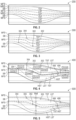
- a system tract interval diagram 200 illustrates the system tract intervals (TST, HST, LST) and their respective actual top surfaces (MFS, SB, MRS) within an exemplary gross interval thickness and a predetermined depositional sequence range of two (2).
- step 106 one or more MRS shoreline facies positions are identified for each MRS actual top surface created in step 104 using paleographic maps and techniques well known in the art.
- one or more LST termination positions are calculated against respective sequence boundary positions using the MRS shoreline facies positions identified in step 106.
- Each termination position is calculated as a predetermined distance (e.g., 10 kilometers) landward of a respective MRS shoreline facies position. The predetermined distance can vary.
- Each termination position determines the up-dip limit of the LST system tract interval, which is the position whereby the proportional thickness of the LST system tract interval is known to be zero.
- a system tract interval diagram 300 illustrates the system tract intervals (TST, HST, LST) and their respective actual top surfaces (MFS, SB, MRS) in FIG. 2 with the MRS shoreline facies positions 302 and the LST termination positions 304.
- lateral zones are defined within the gross interval thickness calculated in step 102 using each LST termination position calculated in step 108 and each MRS shoreline facies position identified in step 106.
- a system tract interval diagram 400 illustrates exemplary lateral zones for the system tract interval diagram 300 in FIG. 3 .
- each zone 1 is updip of an LST termination position 304
- each zone 2 is between an LST termination position 304 and an MRS shoreline facies position 302
- each zone 3 is between an MRS shoreline facies position 302 and a toe of slope (TOS) position 406
- each zone 4 is seaward of the TOS positions 406.
- the TOS positions represent the transition from slope to basinal facies and are determined as a function of surface slope.
- step 110 different conceptual geologic rules are created for each system tract interval created in step 104 as a function of each lateral zone defined in step 109.
- the conceptual geologic rules generally fit the pattern of systems tract interval proportional thicknesses observed for depositional sequences across the globe.
- the following conceptual geologic rules are established for depositional sequence fill patterns (geometries and thickening and thinning patterns), which can be translated into formal mathematical calculations:
- step 112 new actual top surfaces for each system tract interval (TST, HST, LST) are created within the gross interval thickness calculated in step 102 using the conceptual geologic rule(s) defined in step 110.
- the creation of the new actual top surfaces for each system tract interval may be illustrated by tables 1 and 2 below. Each column in tables 1 and 2 represents a different dip position across the basin profile (columns 1-17) from landward positions on the left to seaward positions on the right.
- the LST termination positions, MRS shoreline facies positions and TOS positions for two complete sequences, which are used to define the lateral zones in FIG. 4 are labeled across the top.
- an up-dip location includes two TST and two HST system tract intervals (there are no LST system tract intervals up-dip).
- the conceptual geologic rule created in step 110 e.g. HST thickness is 2 times the TST thickness
- HST thickness is 2 times the TST thickness
- LST system tract interval proportionality ratio is zero.
- the product of the proportionality variable (16.67) times the proportionality ratio (rows1-6) yields each system tract interval thickness.
- the TST and HST system tract interval thicknesses are thus, 16.67 meters and 33.34 meters, respectively.
- the new actual top surfaces for each system tract interval are thus, created by summing the interval thickness calculations for a given system tract interval at each dip location across the entire basin (columns 1-17).
- Table 2 includes the new actual top surfaces (depths as negative numbers) created for each system tract interval across the entire basin.
- a far down-dip location includes two TST, two HST and two LST system tract intervals.
- the conceptual geologic rule created in step 110 e.g. LST thickness is 4 times TST thicknesses and HST thickness is 2 times TST thickness
- the proportionality ratio is four.
- the product of the proportionality variable (7.1) times the proportionality ratio (rows 1-6) yields each system tract interval thickness.
- the LST, HST and TST system tract interval thicknesses are thus, 56.8 meters, 28.4 meters and 14.2 meters, respectively.
- a system tract interval diagram 500 illustrates exemplary new actual top surfaces for each system tract interval (TST, HST, LST) compared to the actual top surfaces in FIG. 2 .
- a new well has been added with well picks (cross-marks), which represent correlations to top surfaces. When a new well is added, there is likely to be a difference between the new actual surfaces and the well picks.
- step 116 the method 100 determines if there are any well picks for each well in the gross interval thickness calculated in step 102. If there is no well pick for each well, then the method 100 ends. Otherwise, the method 100 proceeds to step 118.
- each new actual top surface created in step 112 that does not intersect a corresponding well pick on a well with well picks is adjusted within a predetermined distance from the respective well to intersect the corresponding well pick.
- the method 100 may end or repeat from step 116 if any well position is moved or a new well is added.
- a system tract interval diagram 600 illustrates the four new actual top surfaces (SB,MFS,MRS,SB) in FIG. 5 that are adjusted within a predetermined distance from the respective well to intersect the corresponding well pick.
- the method 100 enables modeling sequence geometries from sparse data and provides a technique for modeling basin fill geometries and then associating additional properties with them (e.g., additional facies and rock properties data). These models can be updated to honor specific inputs from well control.
- the method 100 thus, improves stratigraphic prediction in order to more accurately determine well positioning.
- the present disclosure may be implemented through a computer-executable program of instructions, such as program modules, generally referred to as software applications or application programs executed by a computer.
- the software may include, for example, routines, programs, objects, components and data structures that perform particular tasks or implement particular abstract data types.
- the software forms an interface to allow a computer to react according to a source of input.
- DecisionSpace ® which is a commercial software application marketed by Landmark Graphics Corporation, may be used as an interface application to implement the present disclosure.
- the software may also cooperate with other code segments to initiate a variety of tasks in response to data received in conjunction with the source of the received data.
- the software may be stored and/or carried on any variety of memory such as CD-ROM, magnetic disk, bubble memory and semiconductor memory (e.g. various types of RAM or ROM).
- the software and its results may be transmitted over a variety of carrier media such as optical fiber, metallic wire and/or through any of a variety of networks, such as the Internet,
- the disclosure may be practiced with a variety of computer-system configurations, including hand-held devices, multiprocessor systems, microprocessor-based or programmable-consumer electronics, minicomputers, mainframe computers, and the like. Any number of computer-systems and computer networks are acceptable for use with the present disclosure.
- the disclosure may be practiced in distributed-computing environments where tasks are performed by remoteprocessing devices that are linked through a communications network.
- program modules may be located in both local and remote computerstorage media including memory storage devices.
- the present disclosure may therefore, be implemented in connection with various hardware, software or a combination thereof, in a computer system or other processing system.
- FIG. 7 a block diagram illustrates one embodiment of a system for implementing the present disclosure on a computer.
- the system includes a computing unit, sometimes referred to as a computing system, which contains memory, application programs, a client interface, a video interface, and a processing unit.
- the computing unit is only one example of a suitable computing environment and is not intended to suggest any limitation as to the scope of use or functionality of the disclosure.
- the memory primarily stores the application programs, which may also be described as program modules containing computer-executable instructions, executed by the computing unit for implementing the present disclosure described herein and illustrated in FIGS. 1-6 .
- the memory therefore, includes a geological sequence modelling module, which enables steps 106-118 described in reference to FIG. 1 .
- the geological sequence modelling module may integrate functionality from the remaining application programs illustrated in FIG. 7 .
- DecisionSpace ® may be used as an interface application to perform steps 102-104 in FIG. 1 .
- Neftex Tm which is a commercial database marketed by Landmark Graphics Corporation, may be used to supply the paleographic maps used in step 106.
- DecisionSpace ® and Neftex Tm may be used as interface application, other interface applications may be used, instead, or the geological sequence modelling module may be used as a stand-alone application.
- the computing unit typically includes a variety of computer readable media.
- computer readable media may comprise computer storage media and communication media.
- the computing system memory may include computer storage media in the form of volatile and/or nonvolatile memory such as a read only memory (ROM) and random access memory (RAM).
- ROM read only memory
- RAM random access memory
- a basic input/output system (BIOS) containing the basic routines that help to transfer information between elements within the computing unit, such as during start-up, is typically stored in ROM.
- the RAM typically contains data and/or program modules that are immediately accessible to, and/or presently being operated on, the processing unit.
- the computing unit includes an operating system, application programs, other program modules, and program data.
- the components shown in the memory may also be included in other removable/nonremovable, volatile/nonvolatile computer storage media or they may be implemented in the computing unit through an application program interface ("API") or cloud computing, which may reside on a separate computing unit connected through a computer system or network.
- API application program interface
- a hard disk drive may read from or write to nonremovable, nonvolatile magnetic media
- a magnetic disk drive may read from or write to a removable, nonvolatile magnetic disk
- an optical disk drive may read from or write to a removable, nonvolatile optical disk such as a CD ROM or other optical media.
- removable/nonremovable, volatile/nonvolatile computer storage media that can be used in the exemplary operating environment may include, but are not limited to, magnetic tape cassettes, flash memory cards, digital versatile disks, digital video tape, solid state RAM, solid state ROM, and the like.
- the drives and their associated computer storage media discussed above provide storage of computer readable instructions, data structures, program modules and other data for the computing unit.
- a client may enter commands and information into the computing unit through the client interface, which may be input devices such as a keyboard and pointing device, commonly referred to as a mouse, trackball or touch pad. Input devices may include a microphone, joystick, satellite dish, scanner, or the like. These and other input devices are often connected to the processing unit through the client interface that is coupled to a system bus, but may be connected by other interface and bus structures, such as a parallel port or a universal serial bus (USB).
- USB universal serial bus
- a monitor or other type of display device may be connected to the system bus via an interface, such as a video interface.
- a graphical user interface may also be used with the video interface to receive instructions from the client interface and transmit instructions to the processing unit.
- computers may also include other peripheral output devices such as speakers and printer, which may be connected through an output peripheral interface.
Description
- The present disclosure generally relates to systems and methods for modelling complex geological sequences using geologic rules and paleographic maps. More particularly, the present disclosure relates to modelling complex geological sequences representing new actual surfaces within a gross interval thickness using geologic rules based on facies data and paleographic maps represented by MRS shoreline facies.
- Modelling complex geological sequences may utilize conventional techniques such as, for example, proportional layering to create stratigraphic subdivisions between grids that represent a more detailed layering of the earth. This technique assumes a parallel and conformable geometric pattern for a gross interval thickness, which is the difference between two gridded surfaces. The gross interval thickness may be appropriate for certain portions of an overall depositional sequence (i.e., the top-set and bottom-set portions), but is inappropriate for the pro-grading, clinoform-dominated portions of the depositional sequence.
- Another conventional technique for modelling complex geological sequences uses proportions and flattens all stratigraphic layers in geologic time in an attempt to restore the subsurface model into a chronostratigraphic model. In doing this, a mathematical technique is applied for proportional layering across the subsurface model. This type of proportional layering technique has limited use when the goal is to model the entire depositional sequence (i.e., for areas with pro-gradational clinoforms that cannot be modeled using conventional approaches to proportional layering).
- Related techniques for modelling complex geological sequences may use automated seismic horizon tracking and model-building to create 3D subsurface models that can be translated into a chronostratigraphic model. The 3D subsurface model is created by direct interpretation of seismic data. In other words, the 3D subsurface model is derived directly from densely sampled seismic data. This technique extracts time-stratigraphic surfaces from seismic data (using coherence attributes) to build a time-stratigraphic 3D subsurface model. Then, the constructed 3D subsurface model is translated into a chronostratigraphic model. This approach can work when available seismic data has a high signal-to-noise ratio. However, in regions of poor quality seismic data, building with this technique is impossible.
-
GB2512372 A -
GB2384304 A -
US2014/278311 A1 discloses a method for modeling one or more geophysical properties of a subsurface volume comprising obtaining an interpretation of a subsurface volume and applying one or more flexible geologic concepts to the interpretation. -
US2015/066460 A1 discloses a method of: receiving implicit function values at nodes of a coarse mesh of a region of interest in a geologic environment; receiving data; formulating constraints based on the data; solving a system of equations for a finer mesh subject to the constraints; and outputting implicit function values at nodes of the finer mesh based on solving the equations. - The present disclosure is described below with references to the accompanying drawings in which like elements are referenced with like reference numerals, and in which:
-
FIG. 1 is a flow diagram illustrating one embodiment of a method for implementing the present disclosure. -
FIG. 2 is a system tract intervaldiagram illustrating step 104 inFIG. 1 . -
FIG. 3 is a system tract intervaldiagram illustrating step 108 inFIG. 1 . -
FIG. 4 is a system tract intervaldiagram illustrating step 109 inFIG. 1 . -
FIG. 5 is a system tract intervaldiagram illustrating step 112 inFIG. 1 . -
FIG. 6 is a system tract intervaldiagram illustrating step 118 inFIG. 1 . -
FIG. 7 is a block diagram illustrating one embodiment of a computer system for implementing the present disclosure. - The present disclosure overcomes one or more deficiencies in the prior art by providing systems and methods for modelling complex geological sequences representing new actual surfaces within a gross interval thickness using geologic rules based on facies data and paleographic maps represented by MRS shoreline facies.
- According to the invention, the present disclosure includes a computer-implemented method for modelling complex geological sequences, the method comprising: i) calculating a gross interval thickness over a predetermined depositional sequence range with three system tract intervals per sequence using a predetermined gross interval defined by two grids representing seismic horizons or well tops; ii) creating actual top surfaces using the gross interval thickness and the predetermined depositional sequence range by subdividing the gross interval thickness by the product of the predetermined depositional sequence range times three; iii) identifying one or more MRS shoreline facies positions for each of the actual top surfaces that is an MRS actual top surface using a paleographic map; iv) calculating one or more LST termination positions against one or more respective sequence boundaries using the respective one or more MRS shoreline facies positions; v) defining lateral zones within the gross interval thickness for each system tract interval using each LST termination position and MRS shoreline facies position; vi) creating conceptual geologic rules for each system tract interval as a function of each lateral zone using proportionality regarding the different system tracts; and vii) creating new actual top surfaces for each system tract interval within the gross interval thickness using the conceptual geological rules; and determining well positioning.
- According to an aspect of the invention, the present disclosure includes a non-transitory program carrier device tangibly carrying computer executable instructions for modelling complex geological sequences, the instructions being executable to implement: i) calculating a gross interval thickness over a predetermined depositional sequence range with three system tract intervals per sequence using a predetermined gross interval defined by two grids representing seismic horizons or well tops; ii) creating actual top surfaces using the gross interval thickness and the predetermined depositional sequence range by subdividing the gross interval thickness by the product of the predetermined depositional sequence range times three; iii) identifying one or more MRS shoreline facies positions for each of the actual top surfaces that is an MRS actual top surface using a paleographic map; iv) calculating one or more LST termination positions against one or more respective sequence boundaries using the respective one or more MRS shoreline facies positions; v) defining lateral zones within the gross interval thickness for each system tract interval using each LST termination position and each MRS shoreline facies position; vi) creating conceptual geologic rules for each system tract interval as a function of each lateral zone using proportionality regarding the different system tracts; and vii) creating new actual top surfaces for each system tract interval within the gross interval thickness using the conceptual geological rules; and determining well positioning.
- The subject matter of the present disclosure is described with specificity, however, the description itself is not intended to limit the scope of the disclosure. The subject matter thus, might also be embodied in other ways, to include different structures, steps and/or combinations similar to those described herein, in conjunction with other present or future technologies. Moreover, although the term "step" may be used herein to describe different elements of methods employed, the term should not be interpreted as implying any particular order among or between various steps herein disclosed unless otherwise expressly limited by the description to a particular order. While the present disclosure may be described with respect to the oil and gas industry, it is not limited thereto and may also be applied in other industries (e.g. drilling water wells) to achieve similar results.
- Referring now to
FIG. 1 , a flow diagram illustrates one embodiment of amethod 100 for implementing the present disclosure. Themethod 100 enables proportional or stratigraphic subdivisions across the entire depositional sequence to build a 3D model of depositional sequences using sparse data. Distinctive features of themethod 100 include: 1) the use of facies data (paleo shorelines and shelf edges) as a means of guiding geologic rules for 3D sequence modeling; and 2) the use of proportionality as a means of carrying or describing the geologic rules. - In
step 102, a gross interval thickness over a predetermined depositional sequence range with three system tract intervals per sequence (TST, HST, LST) is calculated using a predetermined gross interval defined by two grids representing seismic horizons or well tops (derived from seismic data retrieved from sensors) and techniques well known in the art. TST is the transgressive systems tract, HST is the highstand systems tract, and LST is the lowstand systems tract. MFS is the maximum flooding surface, which is the top of the TST. The SB is the sequence boundary, which is the top of the HST. And MRS is the maximum regressive surface, which is the top of the LST. - In
step 104, actual top surfaces and system tract intervals (TST, HST, LST) are created by proportionally subdividing the gross interval thickness calculated instep 102 by the product of the predetermined depositional sequence range (i.e., how many sequences) times three (system tract intervals). Each system tract interval lies between the actual top surface (MFS, MRS, SB) and an actual bottom surface, InFIG. 2 , a system tract interval diagram 200 illustrates the system tract intervals (TST, HST, LST) and their respective actual top surfaces (MFS, SB, MRS) within an exemplary gross interval thickness and a predetermined depositional sequence range of two (2). - In
step 106, one or more MRS shoreline facies positions are identified for each MRS actual top surface created instep 104 using paleographic maps and techniques well known in the art. - In
step 108, one or more LST termination positions are calculated against respective sequence boundary positions using the MRS shoreline facies positions identified instep 106. Each termination position is calculated as a predetermined distance (e.g., 10 kilometers) landward of a respective MRS shoreline facies position. The predetermined distance can vary. Each termination position determines the up-dip limit of the LST system tract interval, which is the position whereby the proportional thickness of the LST system tract interval is known to be zero. InFIG. 3 , a system tract interval diagram 300 illustrates the system tract intervals (TST, HST, LST) and their respective actual top surfaces (MFS, SB, MRS) inFIG. 2 with the MRSshoreline facies positions 302 and theLST termination positions 304. - In
step 109, lateral zones are defined within the gross interval thickness calculated instep 102 using each LST termination position calculated instep 108 and each MRS shoreline facies position identified instep 106. InFIG. 4 , a system tract interval diagram 400 illustrates exemplary lateral zones for the system tract interval diagram 300 inFIG. 3 . For a given depositional sequence, each zone 1 is updip of anLST termination position 304, each zone 2 is between anLST termination position 304 and an MRSshoreline facies position 302, each zone 3 is between an MRSshoreline facies position 302 and a toe of slope (TOS)position 406 and each zone 4 is seaward of theTOS positions 406. The TOS positions represent the transition from slope to basinal facies and are determined as a function of surface slope. - In
step 110, different conceptual geologic rules are created for each system tract interval created instep 104 as a function of each lateral zone defined instep 109. The conceptual geologic rules generally fit the pattern of systems tract interval proportional thicknesses observed for depositional sequences across the globe. The following conceptual geologic rules are established for depositional sequence fill patterns (geometries and thickening and thinning patterns), which can be translated into formal mathematical calculations: - In zones 1 and 4, the rules reflect system tract intervals that maintain a parallel relationship to one another. In zones 2 and 3, the rules reflect rapid thickness changes that correspond to slope deposition;
- The TST generally thins into the basin;
- HST and LST have a negative proportional relationship - as one gets thicker, the other gets thinner;
- The LST has its maximum absolute thickness at the MRS shoreline facies position and/or shelf edge;
- The LST thins from the MRS shoreline facies position to the LST termination position; and
- The LST thins from the MRS shoreline facies position to the TOS.
- In
step 112, new actual top surfaces for each system tract interval (TST, HST, LST) are created within the gross interval thickness calculated instep 102 using the conceptual geologic rule(s) defined instep 110. The creation of the new actual top surfaces for each system tract interval may be illustrated by tables 1 and 2 below. Each column in tables 1 and 2 represents a different dip position across the basin profile (columns 1-17) from landward positions on the left to seaward positions on the right. The LST termination positions, MRS shoreline facies positions and TOS positions for two complete sequences, which are used to define the lateral zones inFIG. 4 , are labeled across the top. In column 1 of table 1, for example, an up-dip location includes two TST and two HST system tract intervals (there are no LST system tract intervals up-dip). The conceptual geologic rule created in step 110 (e.g. HST thickness is 2 times the TST thickness) for these system tract intervals is represented in rows 1-6 of column 1 as the proportionality ratio, wherein the LST system tract interval proportionality ratio is zero. Using the gross interval thickness (100 meters in column 1) calculated instep 102 and the conceptual geologic rule created instep 110, the proportionality variable may be calculated by solving for X in the following equation: 100=2((2X (HST)) + 2((1X (TST)) or 100=4X+2X wherein X=16.67, The product of the proportionality variable (16.67) times the proportionality ratio (rows1-6) yields each system tract interval thickness. The TST and HST system tract interval thicknesses are thus, 16.67 meters and 33.34 meters, respectively. The new actual top surfaces for each system tract interval are thus, created by summing the interval thickness calculations for a given system tract interval at each dip location across the entire basin (columns 1-17). Table 2 includes the new actual top surfaces (depths as negative numbers) created for each system tract interval across the entire basin. In column 17 of table 1, as another example, a far down-dip location includes two TST, two HST and two LST system tract intervals. The conceptual geologic rule created in step 110 (e.g. LST thickness is 4 times TST thicknesses and HST thickness is 2 times TST thickness) for these system tract intervals is represented in rows 1-6 of column 17 as the proportionality ratio, wherein the LST system tract interval proportionality ratio is four. Using the gross interval thickness (100 meters in column 17) calculated instep 102 and the conceptual geologic rule created instep 110, the proportionality variable may be calculated by solving for X in the following equation: 100=2((4X (LST)) + 2(2X (HST)) + 2(1X (TST)) or 100= 8X+4X+2X wherein X = 7.1. The product of the proportionality variable (7.1) times the proportionality ratio (rows 1-6) yields each system tract interval thickness. The LST, HST and TST system tract interval thicknesses are thus, 56.8 meters, 28.4 meters and 14.2 meters, respectively. The new actual top surfaces for each system tract interval are thus, created by summing the interval thickness calculations for a given system tract interval at each dip location across the entire basin (columns 1-17). Table 2 includes the new actual top surfaces (depths as negative numbers) created for each system tract interval across the entire basin. InFIG. 5 , a system tract interval diagram 500 illustrates exemplary new actual top surfaces for each system tract interval (TST, HST, LST) compared to the actual top surfaces inFIG. 2 . A new well has been added with well picks (cross-marks), which represent correlations to top surfaces. When a new well is added, there is likely to be a difference between the new actual surfaces and the well picks.

- In
step 116, themethod 100 determines if there are any well picks for each well in the gross interval thickness calculated instep 102. If there is no well pick for each well, then themethod 100 ends. Otherwise, themethod 100 proceeds to step 118. - In
step 118, each new actual top surface created instep 112 that does not intersect a corresponding well pick on a well with well picks is adjusted within a predetermined distance from the respective well to intersect the corresponding well pick. Themethod 100 may end or repeat fromstep 116 if any well position is moved or a new well is added. InFIG. 6 , a system tract interval diagram 600 illustrates the four new actual top surfaces (SB,MFS,MRS,SB) inFIG. 5 that are adjusted within a predetermined distance from the respective well to intersect the corresponding well pick. - The
method 100 enables modeling sequence geometries from sparse data and provides a technique for modeling basin fill geometries and then associating additional properties with them (e.g., additional facies and rock properties data). These models can be updated to honor specific inputs from well control. Themethod 100 thus, improves stratigraphic prediction in order to more accurately determine well positioning. - The present disclosure may be implemented through a computer-executable program of instructions, such as program modules, generally referred to as software applications or application programs executed by a computer. The software may include, for example, routines, programs, objects, components and data structures that perform particular tasks or implement particular abstract data types. The software forms an interface to allow a computer to react according to a source of input. DecisionSpace®, which is a commercial software application marketed by Landmark Graphics Corporation, may be used as an interface application to implement the present disclosure. The software may also cooperate with other code segments to initiate a variety of tasks in response to data received in conjunction with the source of the received data. The software may be stored and/or carried on any variety of memory such as CD-ROM, magnetic disk, bubble memory and semiconductor memory (e.g. various types of RAM or ROM). Furthermore, the software and its results may be transmitted over a variety of carrier media such as optical fiber, metallic wire and/or through any of a variety of networks, such as the Internet,
- Moreover, those skilled in the art will appreciate that the disclosure may be practiced with a variety of computer-system configurations, including hand-held devices, multiprocessor systems, microprocessor-based or programmable-consumer electronics, minicomputers, mainframe computers, and the like. Any number of computer-systems and computer networks are acceptable for use with the present disclosure. The disclosure may be practiced in distributed-computing environments where tasks are performed by remoteprocessing devices that are linked through a communications network. In a distributed-computing environment, program modules may be located in both local and remote computerstorage media including memory storage devices. The present disclosure may therefore, be implemented in connection with various hardware, software or a combination thereof, in a computer system or other processing system.
- Referring now to
FIG. 7 , a block diagram illustrates one embodiment of a system for implementing the present disclosure on a computer. The system includes a computing unit, sometimes referred to as a computing system, which contains memory, application programs, a client interface, a video interface, and a processing unit. The computing unit is only one example of a suitable computing environment and is not intended to suggest any limitation as to the scope of use or functionality of the disclosure. - The memory primarily stores the application programs, which may also be described as program modules containing computer-executable instructions, executed by the computing unit for implementing the present disclosure described herein and illustrated in
FIGS. 1-6 . The memory therefore, includes a geological sequence modelling module, which enables steps 106-118 described in reference toFIG. 1 . The geological sequence modelling module may integrate functionality from the remaining application programs illustrated inFIG. 7 . In particular, DecisionSpace® may be used as an interface application to perform steps 102-104 inFIG. 1 . NeftexTm, which is a commercial database marketed by Landmark Graphics Corporation, may be used to supply the paleographic maps used instep 106. Although DecisionSpace® and NeftexTm may be used as interface application, other interface applications may be used, instead, or the geological sequence modelling module may be used as a stand-alone application. - Although the computing unit is shown as having a generalized memory, the computing unit typically includes a variety of computer readable media. By way of example, and not limitation, computer readable media may comprise computer storage media and communication media. The computing system memory may include computer storage media in the form of volatile and/or nonvolatile memory such as a read only memory (ROM) and random access memory (RAM). A basic input/output system (BIOS), containing the basic routines that help to transfer information between elements within the computing unit, such as during start-up, is typically stored in ROM. The RAM typically contains data and/or program modules that are immediately accessible to, and/or presently being operated on, the processing unit. By way of example, and not limitation, the computing unit includes an operating system, application programs, other program modules, and program data.
- The components shown in the memory may also be included in other removable/nonremovable, volatile/nonvolatile computer storage media or they may be implemented in the computing unit through an application program interface ("API") or cloud computing, which may reside on a separate computing unit connected through a computer system or network. For example only, a hard disk drive may read from or write to nonremovable, nonvolatile magnetic media, a magnetic disk drive may read from or write to a removable, nonvolatile magnetic disk, and an optical disk drive may read from or write to a removable, nonvolatile optical disk such as a CD ROM or other optical media. Other removable/nonremovable, volatile/nonvolatile computer storage media that can be used in the exemplary operating environment may include, but are not limited to, magnetic tape cassettes, flash memory cards, digital versatile disks, digital video tape, solid state RAM, solid state ROM, and the like. The drives and their associated computer storage media discussed above provide storage of computer readable instructions, data structures, program modules and other data for the computing unit.
- A client may enter commands and information into the computing unit through the client interface, which may be input devices such as a keyboard and pointing device, commonly referred to as a mouse, trackball or touch pad. Input devices may include a microphone, joystick, satellite dish, scanner, or the like. These and other input devices are often connected to the processing unit through the client interface that is coupled to a system bus, but may be connected by other interface and bus structures, such as a parallel port or a universal serial bus (USB).
- A monitor or other type of display device may be connected to the system bus via an interface, such as a video interface. A graphical user interface ("GUI") may also be used with the video interface to receive instructions from the client interface and transmit instructions to the processing unit. In addition to the monitor, computers may also include other peripheral output devices such as speakers and printer, which may be connected through an output peripheral interface.
- Although many other internal components of the computing unit are not shown, those of ordinary skill in the art will appreciate that such components and their interconnection are well-known.
- While the present disclosure has been described in connection with presently preferred embodiments, it will be understood by those skilled in the art that it is not intended to limit the disclosure to those embodiments. It is therefore, contemplated that various alternative embodiments and modifications may be made to the disclosed embodiments without departing from the scope of the disclosure as defined by the appended claims.
Claims (9)
- A computer-implemented method for modelling complex geological sequences, the method comprising:calculating (102) a gross interval thickness over a predetermined depositional sequence range with three system tract intervals per sequence using a predetermined gross interval defined by two grids representing seismic horizons or well tops; the method being characterized increating (104) actual top surfaces using the gross interval thickness and the predetermined depositional sequence range by proportionally subdividing the gross interval thickness by the product of the predetermined depositional sequence range times three;identifying (106) one or more maximum regression surface, MRS, shoreline facies positions (302) for each of the actual top surfaces that is an MRS actual top surface using a paleographic map;calculating (108) one or more lowstand system tracts, LST, termination positions (304) against one or more respective sequence boundaries using the respective one or more MRS shoreline facies positions (302) ;defining (109) lateral zones within the gross interval thickness for each system tract interval using each respective LST termination position (302) and MRS shoreline facies position (304);creating (110) conceptual geologic rules for each system tract interval as a function of each lateral zone using proportionality regarding the different system tracts; andcreating (112) new actual top surfaces for each system tract interval within the gross interval thickness using the conceptual geologic rules; and determining a well positioning.
- The method of claim 1, wherein the creating actual top surfaces comprises creating each actual top surface and each system tract interval by proportionally subdividing the gross interval thickness by a product of the predetermined depositional sequence range times the number of system tract intervals per sequence.
- The method of any preceding claim, further comprising adjusting each new actual top surface, which does not intersect a corresponding well pick on a well with well picks, within a predetermined distance from the respective well to interest the corresponding well pick.
- The method of any preceding claim, wherein four lateral zones are defined within the gross interval thickness.
- The method of claim 4, wherein a first zone is defined updip of one of the one or more LST termination positions, a second zone is defined between one of the one or more LST termination positions and the respective MRS shoreline facies position, a third zone is defined between the respective MRS shoreline facies position and a TOS position, and a fourth zone is defined seaward of the TOS position.
- The method of claim 5, wherein the conceptual geologic rules for each system tract interval require the first lateral zone and the fourth lateral zone to maintain a parallel relationship.
- The method of claim 5, wherein the conceptual geologic rules for each system tract interval require the second lateral zone and the third lateral zone to reflect rapid thickness changes that correspond to slope deposition.
- A non-transitory program carrier device tangibly carrying computer executable instructions for modelling complex geological sequences, the instructions being executable to implement:calculating (102) a gross interval thickness over a predetermined depositional sequence range with three system tract intervals per sequence using a predetermined gross interval defined by two grids representing seismic horizons or well tops; characterized increating (104) actual top surfaces using the gross interval thickness and the predetermined depositional sequence range by proportionally subdividing the gross interval thickness by the product of the predetermined depositional sequence range times three;identifying (106) one or more maximum regression surface, MRS, shoreline facies positions (302) for each of the actual top surfaces that is an MRS actual top surface using a paleographic map;calculating (108) one or more lowstand system tracts, LST, termination positions (304) against one or more respective sequence boundaries using the respective one or more MRS shoreline facies positions (302);defining (109) lateral zones within the gross interval thickness for each system tract interval using each respective LST termination position (302) and each MRS shoreline facies position (304);creating (110) conceptual geologic rules for each system tract interval as a function of each lateral zone using proportionality regarding the different system tracts; andcreating (112) new actual top surfaces for each system tract interval within the gross interval thickness using the conceptual geologic rules; and determining a well positioning.
- The program carrier device of claim 8, wherein the creating actual top surfaces comprises creating each actual top surface and each system tract interval by proportionally subdividing the gross interval thickness by a product of the predetermined depositional sequence range times the number of system tract intervals per sequence.
Applications Claiming Priority (1)
| Application Number | Priority Date | Filing Date | Title |
|---|---|---|---|
| PCT/US2015/059687 WO2017082856A1 (en) | 2015-11-09 | 2015-11-09 | Modelling complex geological sequences using geologic rules and paleographic maps |
Publications (3)
| Publication Number | Publication Date |
|---|---|
| EP3374969A1 EP3374969A1 (en) | 2018-09-19 |
| EP3374969A4 EP3374969A4 (en) | 2019-08-21 |
| EP3374969B1 true EP3374969B1 (en) | 2023-06-14 |
Family
ID=58694826
Family Applications (1)
| Application Number | Title | Priority Date | Filing Date |
|---|---|---|---|
| EP15908407.8A Active EP3374969B1 (en) | 2015-11-09 | 2015-11-09 | Modelling complex geological sequences using geologic rules and paleographic maps |
Country Status (5)
| Country | Link |
|---|---|
| US (1) | US10145986B2 (en) |
| EP (1) | EP3374969B1 (en) |
| AU (1) | AU2015414299A1 (en) |
| CA (1) | CA3001119C (en) |
| WO (1) | WO2017082856A1 (en) |
Families Citing this family (7)
| Publication number | Priority date | Publication date | Assignee | Title |
|---|---|---|---|---|
| FR3039679B1 (en) * | 2015-07-30 | 2018-08-10 | Services Petroliers Schlumberger | ASSIGNMENT OF SEDIMENTARY SEQUENCES |
| CA3081686A1 (en) * | 2017-12-29 | 2019-07-04 | Landmark Graphics Corporation | Modeling complex basin fill utilizing known shoreline data |
| CN109801552B (en) * | 2019-01-24 | 2020-11-27 | 中国人民解放军战略支援部队信息工程大学 | Method for simplifying artificial coastline |
| CN111681314B (en) * | 2020-05-29 | 2021-04-06 | 中国地质大学(武汉) | Virtual contour constraint-based fourth-system covering layer three-dimensional modeling method |
| CN111983678B (en) * | 2020-07-22 | 2024-02-23 | 中海石油(中国)有限公司深圳分公司 | Method for rapidly evaluating development potential of deep water sand body |
| CN112579688B (en) * | 2020-12-11 | 2022-10-18 | 山东科技大学 | Mining method, device, equipment and medium of spatial association rule |
| CN113158274B (en) * | 2021-05-08 | 2022-07-05 | 北京金阳普泰石油技术股份有限公司 | Method and system for modeling sand body between wells |
Family Cites Families (8)
| Publication number | Priority date | Publication date | Assignee | Title |
|---|---|---|---|---|
| GB2384304B (en) * | 2002-01-04 | 2003-12-03 | Nigel Allister Anstey | Method of distinguishing types of geologic sedimentation |
| US20110320182A1 (en) | 2007-08-01 | 2011-12-29 | Austin Geomodeling | Method and system for dynamic, three-dimensional geological interpretation and modeling |
| MX2010008182A (en) * | 2008-01-28 | 2010-08-18 | Landmark Graphics Corp | Hybrid stratigraphic layering using pseudo-wheeler space. |
| AU2011258764B2 (en) | 2010-05-28 | 2014-10-23 | Exxonmobil Upstream Research Company | Method for seismic hydrocarbon system analysis |
| US9081918B2 (en) * | 2011-01-27 | 2015-07-14 | Landmark Graphics Corporation | Methods and systems regarding models of underground formations |
| US9733391B2 (en) | 2013-03-15 | 2017-08-15 | Exxonmobil Upstream Research Company | Method and system for geophysical modeling of subsurface volumes |
| GB2512372B (en) * | 2013-03-28 | 2020-07-29 | Total Sa | Method of modelling a subsurface volume |
| GB2531976B (en) | 2013-08-30 | 2020-12-16 | Logined Bv | Stratigraphic function |
-
2015
- 2015-11-09 AU AU2015414299A patent/AU2015414299A1/en not_active Abandoned
- 2015-11-09 WO PCT/US2015/059687 patent/WO2017082856A1/en active Application Filing
- 2015-11-09 US US15/323,789 patent/US10145986B2/en active Active
- 2015-11-09 EP EP15908407.8A patent/EP3374969B1/en active Active
- 2015-11-09 CA CA3001119A patent/CA3001119C/en active Active
Also Published As
| Publication number | Publication date |
|---|---|
| CA3001119C (en) | 2020-09-29 |
| CA3001119A1 (en) | 2017-05-18 |
| EP3374969A4 (en) | 2019-08-21 |
| EP3374969A1 (en) | 2018-09-19 |
| US10145986B2 (en) | 2018-12-04 |
| AU2015414299A1 (en) | 2018-04-12 |
| WO2017082856A1 (en) | 2017-05-18 |
| US20170315265A1 (en) | 2017-11-02 |
Similar Documents
| Publication | Publication Date | Title |
|---|---|---|
| EP3374969B1 (en) | Modelling complex geological sequences using geologic rules and paleographic maps | |
| EP3329307B1 (en) | Assignment of systems tracts | |
| EP2888606B1 (en) | Method and system for 3d seismic data depth conversion utilizing artificial neural networks | |
| US20160124116A1 (en) | Generation of structural elements for subsurface formation using stratigraphic implicit function | |
| AU2016391066B2 (en) | Optimized geosteering using real-time geological models | |
| US20150285950A1 (en) | Systems and Methods for Selecting Facies Model Realizations | |
| Ketineni et al. | Structuring an integrative approach for field development planning using artificial intelligence and its application to an offshore oilfield | |
| Gogia et al. | Tracking 3D seismic horizons with a new hybrid tracking algorithm | |
| CA3036669C (en) | Avoiding geological formation boundaries during drilling operations | |
| CN109991663A (en) | Work area seismic velocity sports school correction method and device | |
| US11397278B2 (en) | Determining a numerical age for geological events within a scheme | |
| AU2019232767A1 (en) | Determining appraisal locations in a reservoir system | |
| US20190004197A1 (en) | Updating models of complex geological sequences field of the disclosure | |
| McCormick et al. | Integration of analog data for building testable, deterministic geological models in a common interpretation environment: An example from the Atokan Boonsville gas field, Fort Worth Basin, Texas |
Legal Events
| Date | Code | Title | Description |
|---|---|---|---|
| STAA | Information on the status of an ep patent application or granted ep patent |
Free format text: STATUS: THE INTERNATIONAL PUBLICATION HAS BEEN MADE |
|
| PUAI | Public reference made under article 153(3) epc to a published international application that has entered the european phase |
Free format text: ORIGINAL CODE: 0009012 |
|
| STAA | Information on the status of an ep patent application or granted ep patent |
Free format text: STATUS: REQUEST FOR EXAMINATION WAS MADE |
|
| 17P | Request for examination filed |
Effective date: 20180327 |
|
| AK | Designated contracting states |
Kind code of ref document: A1 Designated state(s): AL AT BE BG CH CY CZ DE DK EE ES FI FR GB GR HR HU IE IS IT LI LT LU LV MC MK MT NL NO PL PT RO RS SE SI SK SM TR |
|
| AX | Request for extension of the european patent |
Extension state: BA ME |
|
| DAV | Request for validation of the european patent (deleted) | ||
| DAX | Request for extension of the european patent (deleted) | ||
| A4 | Supplementary search report drawn up and despatched |
Effective date: 20190724 |
|
| RIC1 | Information provided on ipc code assigned before grant |
Ipc: G01V 99/00 20090101ALI20190718BHEP Ipc: G01V 1/30 20060101ALI20190718BHEP Ipc: G06T 17/05 20110101AFI20190718BHEP |
|
| STAA | Information on the status of an ep patent application or granted ep patent |
Free format text: STATUS: EXAMINATION IS IN PROGRESS |
|
| 17Q | First examination report despatched |
Effective date: 20220719 |
|
| GRAP | Despatch of communication of intention to grant a patent |
Free format text: ORIGINAL CODE: EPIDOSNIGR1 |
|
| STAA | Information on the status of an ep patent application or granted ep patent |
Free format text: STATUS: GRANT OF PATENT IS INTENDED |
|
| INTG | Intention to grant announced |
Effective date: 20230322 |
|
| GRAS | Grant fee paid |
Free format text: ORIGINAL CODE: EPIDOSNIGR3 |
|
| GRAA | (expected) grant |
Free format text: ORIGINAL CODE: 0009210 |
|
| STAA | Information on the status of an ep patent application or granted ep patent |
Free format text: STATUS: THE PATENT HAS BEEN GRANTED |
|
| AK | Designated contracting states |
Kind code of ref document: B1 Designated state(s): AL AT BE BG CH CY CZ DE DK EE ES FI FR GB GR HR HU IE IS IT LI LT LU LV MC MK MT NL NO PL PT RO RS SE SI SK SM TR |
|
| REG | Reference to a national code |
Ref country code: CH Ref legal event code: EP |
|
| REG | Reference to a national code |
Ref country code: DE Ref legal event code: R096 Ref document number: 602015084232 Country of ref document: DE |
|
| P01 | Opt-out of the competence of the unified patent court (upc) registered |
Effective date: 20230530 |
|
| REG | Reference to a national code |
Ref country code: AT Ref legal event code: REF Ref document number: 1579774 Country of ref document: AT Kind code of ref document: T Effective date: 20230715 |
|
| REG | Reference to a national code |
Ref country code: NO Ref legal event code: T2 Effective date: 20230614 |
|
| REG | Reference to a national code |
Ref country code: LT Ref legal event code: MG9D |
|
| REG | Reference to a national code |
Ref country code: NL Ref legal event code: MP Effective date: 20230614 |
|
| PG25 | Lapsed in a contracting state [announced via postgrant information from national office to epo] |
Ref country code: SE Free format text: LAPSE BECAUSE OF FAILURE TO SUBMIT A TRANSLATION OF THE DESCRIPTION OR TO PAY THE FEE WITHIN THE PRESCRIBED TIME-LIMIT Effective date: 20230614 Ref country code: ES Free format text: LAPSE BECAUSE OF FAILURE TO SUBMIT A TRANSLATION OF THE DESCRIPTION OR TO PAY THE FEE WITHIN THE PRESCRIBED TIME-LIMIT Effective date: 20230614 |
|
| PGFP | Annual fee paid to national office [announced via postgrant information from national office to epo] |
Ref country code: GB Payment date: 20230907 Year of fee payment: 9 |
|
| REG | Reference to a national code |
Ref country code: AT Ref legal event code: MK05 Ref document number: 1579774 Country of ref document: AT Kind code of ref document: T Effective date: 20230614 |
|
| PG25 | Lapsed in a contracting state [announced via postgrant information from national office to epo] |
Ref country code: RS Free format text: LAPSE BECAUSE OF FAILURE TO SUBMIT A TRANSLATION OF THE DESCRIPTION OR TO PAY THE FEE WITHIN THE PRESCRIBED TIME-LIMIT Effective date: 20230614 Ref country code: NL Free format text: LAPSE BECAUSE OF FAILURE TO SUBMIT A TRANSLATION OF THE DESCRIPTION OR TO PAY THE FEE WITHIN THE PRESCRIBED TIME-LIMIT Effective date: 20230614 Ref country code: LV Free format text: LAPSE BECAUSE OF FAILURE TO SUBMIT A TRANSLATION OF THE DESCRIPTION OR TO PAY THE FEE WITHIN THE PRESCRIBED TIME-LIMIT Effective date: 20230614 Ref country code: LT Free format text: LAPSE BECAUSE OF FAILURE TO SUBMIT A TRANSLATION OF THE DESCRIPTION OR TO PAY THE FEE WITHIN THE PRESCRIBED TIME-LIMIT Effective date: 20230614 Ref country code: HR Free format text: LAPSE BECAUSE OF FAILURE TO SUBMIT A TRANSLATION OF THE DESCRIPTION OR TO PAY THE FEE WITHIN THE PRESCRIBED TIME-LIMIT Effective date: 20230614 Ref country code: GR Free format text: LAPSE BECAUSE OF FAILURE TO SUBMIT A TRANSLATION OF THE DESCRIPTION OR TO PAY THE FEE WITHIN THE PRESCRIBED TIME-LIMIT Effective date: 20230915 |
|
| PG25 | Lapsed in a contracting state [announced via postgrant information from national office to epo] |
Ref country code: FI Free format text: LAPSE BECAUSE OF FAILURE TO SUBMIT A TRANSLATION OF THE DESCRIPTION OR TO PAY THE FEE WITHIN THE PRESCRIBED TIME-LIMIT Effective date: 20230614 |
|
| PG25 | Lapsed in a contracting state [announced via postgrant information from national office to epo] |
Ref country code: SK Free format text: LAPSE BECAUSE OF FAILURE TO SUBMIT A TRANSLATION OF THE DESCRIPTION OR TO PAY THE FEE WITHIN THE PRESCRIBED TIME-LIMIT Effective date: 20230614 |
|
| PG25 | Lapsed in a contracting state [announced via postgrant information from national office to epo] |
Ref country code: IS Free format text: LAPSE BECAUSE OF FAILURE TO SUBMIT A TRANSLATION OF THE DESCRIPTION OR TO PAY THE FEE WITHIN THE PRESCRIBED TIME-LIMIT Effective date: 20231014 |
|
| PG25 | Lapsed in a contracting state [announced via postgrant information from national office to epo] |
Ref country code: SM Free format text: LAPSE BECAUSE OF FAILURE TO SUBMIT A TRANSLATION OF THE DESCRIPTION OR TO PAY THE FEE WITHIN THE PRESCRIBED TIME-LIMIT Effective date: 20230614 Ref country code: SK Free format text: LAPSE BECAUSE OF FAILURE TO SUBMIT A TRANSLATION OF THE DESCRIPTION OR TO PAY THE FEE WITHIN THE PRESCRIBED TIME-LIMIT Effective date: 20230614 Ref country code: RO Free format text: LAPSE BECAUSE OF FAILURE TO SUBMIT A TRANSLATION OF THE DESCRIPTION OR TO PAY THE FEE WITHIN THE PRESCRIBED TIME-LIMIT Effective date: 20230614 Ref country code: PT Free format text: LAPSE BECAUSE OF FAILURE TO SUBMIT A TRANSLATION OF THE DESCRIPTION OR TO PAY THE FEE WITHIN THE PRESCRIBED TIME-LIMIT Effective date: 20231016 Ref country code: IS Free format text: LAPSE BECAUSE OF FAILURE TO SUBMIT A TRANSLATION OF THE DESCRIPTION OR TO PAY THE FEE WITHIN THE PRESCRIBED TIME-LIMIT Effective date: 20231014 Ref country code: EE Free format text: LAPSE BECAUSE OF FAILURE TO SUBMIT A TRANSLATION OF THE DESCRIPTION OR TO PAY THE FEE WITHIN THE PRESCRIBED TIME-LIMIT Effective date: 20230614 Ref country code: CZ Free format text: LAPSE BECAUSE OF FAILURE TO SUBMIT A TRANSLATION OF THE DESCRIPTION OR TO PAY THE FEE WITHIN THE PRESCRIBED TIME-LIMIT Effective date: 20230614 Ref country code: AT Free format text: LAPSE BECAUSE OF FAILURE TO SUBMIT A TRANSLATION OF THE DESCRIPTION OR TO PAY THE FEE WITHIN THE PRESCRIBED TIME-LIMIT Effective date: 20230614 |
|
| PGFP | Annual fee paid to national office [announced via postgrant information from national office to epo] |
Ref country code: NO Payment date: 20231023 Year of fee payment: 9 |
|
| PG25 | Lapsed in a contracting state [announced via postgrant information from national office to epo] |
Ref country code: PL Free format text: LAPSE BECAUSE OF FAILURE TO SUBMIT A TRANSLATION OF THE DESCRIPTION OR TO PAY THE FEE WITHIN THE PRESCRIBED TIME-LIMIT Effective date: 20230614 |