CN109801552B - An artificial coastline simplification method - Google Patents
An artificial coastline simplification method Download PDFInfo
- Publication number
- CN109801552B CN109801552B CN201910068952.XA CN201910068952A CN109801552B CN 109801552 B CN109801552 B CN 109801552B CN 201910068952 A CN201910068952 A CN 201910068952A CN 109801552 B CN109801552 B CN 109801552B
- Authority
- CN
- China
- Prior art keywords
- artificial
- coastline
- protruding
- point
- simplification
- Prior art date
- Legal status (The legal status is an assumption and is not a legal conclusion. Google has not performed a legal analysis and makes no representation as to the accuracy of the status listed.)
- Active
Links
Images


Landscapes
- Processing Or Creating Images (AREA)
Abstract
本发明涉及一种人工海岸线化简方法,属于空间数据中模式识别及线要素自动综合技术领域。本发明通过识别构成突出式海岸人工建筑的平行弧段组,从中提取有向中心线,对提取出的有向中心线进行合并、自由点和收缩点移动,得到突出式海岸线人工建筑中心线,实现对突出式海岸人工建筑进行化简;从除突出式海岸建筑外的剩余人工海岸线中提取海侧弯曲单元,并进行化简;对化简结果与突出式海岸线人工建筑中心线存在拓扑冲突进行处理,最终实现人工海岸线的自动化简。整个化简过程,不仅确保了化简结果符合目标尺度下制图要求,还保持了丰富、准确的人工海岸特征,解决了现有人工海岸线化简方法导致的形态失真问题。
The invention relates to an artificial coastline simplification method, which belongs to the technical field of pattern recognition and automatic integration of line elements in spatial data. The invention obtains the center line of the protruding coastline artificial building by identifying the parallel arc segment group constituting the protruding coastal artificial building, extracting the directional centerline therefrom, merging the extracted directional centerline, moving the free point and the shrinking point, and obtaining the protruding coastline artificial building centerline. Realize the simplification of the protruding coastal artificial buildings; extract the seaside curved elements from the remaining artificial coastlines except the protruding coastal buildings, and perform the simplification; carry out the topological conflict between the simplified results and the centerline of the protruding coastal artificial buildings. processing, and ultimately the automation of artificial coastlines. The whole simplification process not only ensures that the simplification results meet the mapping requirements at the target scale, but also maintains the rich and accurate characteristics of artificial coastlines, and solves the problem of morphological distortion caused by existing artificial coastline simplification methods.
Description
技术领域technical field
本发明涉及一种人工海岸线化简方法,属于空间数据中模式识别及线要素自动综合技术领域。The invention relates to an artificial coastline simplification method, which belongs to the technical field of pattern recognition and automatic integration of line elements in spatial data.
背景技术Background technique
线要素化简是制图综合中的重要研究内容和经典研究问题,当前线要素自动化简方法有很多,主要包括节点压缩式、弯曲取舍式和智能算法式等。但通用的线化简方法忽略了不同线要素地理特征差异性,难以保证化简后地理特征完整性以及化简前后地理特征一致性,必须研制专门的海岸线化简方法。顾及海图保障航行的安全性需求,需要研制遵循“扩陆缩海”的原则的海图海岸线自动化简方法。如发表于《武汉大学学报(信息科学版)》2011年第12期上一篇名称为《以弯曲骨架线为化简指标的海岸线综合方法》的论文通过改进单调链法识别弯曲,以弯曲骨架线为综合指标取舍海侧弯曲,专门用于海图海岸线化简。不同类型海岸线间形态差异明显、地理特征各异,针对不同类型海岸线也应研制专门的化简方法,如发表于《Marine Geodesy》2014年第2期中一篇名为《A Simplification of RiaCoastline with Geomorphologic Characteristics Preserved》的论文则针对海图中树枝状溺谷海岸线研制专门的化简方法。Line element simplification is an important research content and a classic research problem in cartographic synthesis. There are many automatic simplification methods for line elements, including node compression, bending and rounding, and intelligent algorithm. However, the general line simplification method ignores the differences in geographic features of different line elements, and it is difficult to ensure the integrity of geographic features after simplification and the consistency of geographic features before and after simplification. Special coastline simplification methods must be developed. Taking into account the safety requirements of charts to ensure navigation, it is necessary to develop a simplified method of chart coastline automation that follows the principle of "expanding the land and shrinking the sea". For example, a paper titled "Comprehensive Method of Shoreline with Curved Skeleton Line as Simplification Index" published in "Journal of Wuhan University (Information Science Edition)" 2011 No. 12 identifies curvature by improving the monotonic chain method to bend the skeleton. The line is the curved sea side of the comprehensive index selection, which is specially used for the simplification of the coastline of the chart. Different types of coastlines have obvious morphological differences and different geographical features, and special simplification methods should also be developed for different types of coastlines. The Preserved paper develops a special simplification method for the shoreline of the dendritic drowning valley in the chart.
上述都是针对自然海岸线的化简,人工海岸线是一种区别于自然海岸线、受人类活动影响显著的常见海岸线。通过人工构筑海岸工程形成的人造海岸线都属于人工海岸线范畴。几何层次看,人工海岸线相对规则、平直;地理层次看,人工海岸包含港口、码头、防波堤等典型海岸人工建筑。依据中国海图图示(GB12319-1998),常见海岸人工建筑在海图中依比例尺表示和半依比例尺表示形式(其中,不具有半依比例尺表达形式的海岸人工建筑称为“顺岸式”海岸人工建筑,顺岸式海岸人工建筑不能降维表达;具有半依比例尺表达形式的海岸人工建筑称为“突出式”海岸人工建筑,突出式海岸人工建筑能够降维表达,如图1-a和图1-b所示。依据降维表达形态差异,包含引桥的突出式海岸人工建筑称为“T”型,不包含引桥的突出式海岸人工建筑称为折线型)。而目前针对人工海岸线化简方法的研究十分匮乏,仅武汉大学2011年博士论文《海岛(礁)要素地图综合数据模型与方法研究》中建议借用多边形化简方法中的最小二乘法化简人工海岸线,此方法过于强调直角特征而容易导致化简后形态失真。The above are all simplifications for natural coastlines. Artificial coastlines are common coastlines that are different from natural coastlines and are significantly affected by human activities. Artificial coastlines formed by artificial construction of coastal engineering belong to the category of artificial coastlines. From the geometric level, the artificial coastline is relatively regular and straight; from the geographical level, the artificial coast includes typical coastal artificial buildings such as ports, wharves, and breakwaters. According to Chinese nautical charts (GB12319-1998), common coastal artificial buildings are represented by scale and semi-scale in the chart (among them, coastal artificial buildings that do not have a semi-scale expression are called "shun shore". Coastal artificial buildings and coastal artificial buildings cannot be expressed in dimensionality reduction; coastal artificial buildings with a semi-scale expression form are called "protruding" coastal artificial buildings, and protruding coastal artificial buildings can be expressed in dimensionality reduction, as shown in Figure 1-a and Figure 1-b. According to the dimensionality reduction expression difference, the protruding coastal artificial building including the approach bridge is called "T" type, and the protruding coastal artificial building not including the approach bridge is called the polyline type). At present, there is very little research on artificial coastline simplification methods. Only in Wuhan University's 2011 doctoral dissertation "Research on Comprehensive Data Model and Method of Island (Reef) Element Map", it is suggested to use the least squares method in the polygon simplification method to simplify artificial coastlines. , this method overemphasizes right-angle features and easily leads to morphological distortion after simplification.
发明内容SUMMARY OF THE INVENTION
本发明的目的是提供一种人工海岸线的化简方法,以解决目前采用多边形化简方法化简人工海岸线导致的化简后形态失真的问题。The purpose of the present invention is to provide a simplification method of artificial coastline, so as to solve the problem of shape distortion after simplification caused by using the polygon simplification method to simplify the artificial coastline.
本发明为解决上述技术问题而提供一种人工海岸线化简方法,该化简方法包括以下步骤:The present invention provides a kind of artificial coastline simplification method in order to solve the above-mentioned technical problem, and this simplification method comprises the following steps:
1)人工海岸线描述:1) Description of artificial coastline:
以顶点顺序递增方向为人工海岸线方向,确保人工海岸线方向一侧为海洋,另一侧为陆地,将人工海岸线描述成相邻顶点构成的有向弧段集合;Take the increasing direction of the vertices as the direction of the artificial coastline, ensure that one side of the direction of the artificial coastline is the ocean and the other side is the land, and describe the artificial coastline as a set of directional arcs formed by adjacent vertices;
2)提取有向中心线:2) Extract the directed centerline:
从有向弧段集合中筛选出构成突出式海岸人工建筑的平行弧段组,提取出每个平行弧段组内的两弧段间的中心线段,并以两弧段中顶点顺序相对靠前弧段的方向作为中心线段的方向,得到各平行弧段组的有向中心线;From the set of directed arcs, filter out the parallel arc segments that constitute the protruding coastal artificial buildings, extract the center line segment between the two arc segments in each parallel arc segment group, and place the vertices in the two arc segments relatively forward in order The direction of the arc segment is taken as the direction of the center line segment, and the oriented center line of each parallel arc segment group is obtained;
3)有向中心线初次合并:3) The first merge of directed centerline:
对有向中心线按照设定的约束条件进行初次合并,所述的设定的约束条件包括:The directional centerlines are merged for the first time according to the set constraints, and the set constraints include:
若两连续的有向中心线有且只有一个公共顶点,将该公共顶点作为连接点将两者合并;If two consecutive directional centerlines have one and only one common vertex, the common vertex is used as the connection point to merge the two;
若两连续的有向中心线没有公共顶点,但具有相交、重叠或者近似重叠的关系,将这两连续的有向中心线进行全连接,并选择全连接中最长的线段作为初次合并的结果;If two consecutive directed centerlines do not have a common vertex, but have an intersecting, overlapping or approximately overlapping relationship, the two continuous directed centerlines are fully connected, and the longest line segment in the full connection is selected as the result of the initial merging ;
4)对初次合并后的有向中心线进行端点移动:4) Move the endpoints of the directional centerline after the initial merge:
所述初次合并后的有向中心线还包含有未参加合并的有向中心线,对初次合并的中心线的自由点和收缩点进行移动,所述自由点指的是有向中心线的终止顶点,所述收缩点指的是有向中心线的起始顶点;The directional centerline after the initial merger also includes the directional centerline that did not participate in the merger, and the free point and the shrinkage point of the initial merged centerline are moved, and the free point refers to the termination of the directional centerline. vertex, the contraction point refers to the starting vertex of the directional centerline;
5)利用端点移动后的有向中心线化简突出式海岸人工建筑:5) Simplify the protruding coastal artificial building by using the directional centerline after the end point is moved:
若构成突出式海岸人工建筑的平行弧段组间最小距离小于制图要求的宽度阈值,则将该平行弧段组对应的经过步骤3)和4)处理后的有向中心线作为对应突出式海岸人工建筑的降维表达,实现对突出式海岸人工建筑的化简;If the minimum distance between the parallel arc segments constituting the protruding coastal artificial building is less than the width threshold required by the drawing, the directional centerline corresponding to the parallel arc segment group processed in steps 3) and 4) will be used as the corresponding protruding coast The dimensionality reduction expression of artificial buildings realizes the simplification of protruding coastal artificial buildings;
6)识别弯曲单元:6) Identify the bending element:
利用拐点法从除突出式海岸建筑外的剩余人工海岸线中提取海侧弯曲单元,删除面积阈值或基线长度小于对应阈值的海侧弯曲单元,得到剩余人工海岸线的化简结果;Using the inflection point method to extract the seaside curved elements from the remaining artificial coastlines except the protruding coastal buildings, delete the seaside curved elements whose area threshold or baseline length is less than the corresponding threshold, and obtain the simplified result of the remaining artificial coastlines;
7)拓扑冲突处理:7) Topological conflict handling:
将剩余人工海岸线化简结果与对应原海岸线部分叠加,以删除部分构成的面状多边形集合记为Bm,若存在有向中心线包含于Bm,则说明存在拓扑冲突,若存在拓扑冲突的有向中心线于Bm外的部分不满足制图视觉要求时,将该有向中心线删除,若存在拓扑冲突的有向中心线于Bm外的部分满足制图视觉要求时,将该有向中心线移动至Bm外。Superimpose the remaining artificial coastline simplification results with the corresponding original coastline, and denote the set of surface polygons formed by the deleted part as B m . If there is a directional centerline included in B m , it means that there is a topological conflict. If there is a topological conflict If the part of the directional centerline outside B m does not meet the visual requirements for cartography, delete the directional centerline; if the part of the directional center line with topological conflicts outside B m meets the visual requirements for cartography, the directional centerline will be deleted. The center line is moved beyond B m .
本发明通过识别构成突出式海岸人工建筑的平行弧段组,从中提取有向中心线,对提取出的有向中心线进行合并、自由点和收缩点移动,得到突出式海岸线人工建筑中心线,实现对突出式海岸人工建筑进行化简;从除突出式海岸建筑外的剩余人工海岸线中提取海侧弯曲单元,并进行化简;对化简结果与突出式海岸线人工建筑中心线存在拓扑冲突进行处理,最终实现人工海岸线的自动化简。整个过程,不仅确保了海岸线化简结果符合目标尺度下制图要求,还保持了丰富、准确的人工海岸特征,解决了现有人工海岸线化简方法导致的形态失真问题。The invention obtains the center line of the protruding coastline artificial building by identifying the parallel arc segment group constituting the protruding coastal artificial building, extracting the directional centerline therefrom, merging the extracted directional centerline, moving the free point and the shrinking point, and obtaining the protruding coastline artificial building centerline. Realize the simplification of the protruding coastal artificial buildings; extract the seaside curved elements from the remaining artificial coastlines except the protruding coastal buildings, and perform the simplification; carry out the topological conflict between the simplified results and the centerline of the protruding coastal artificial buildings. processing, and ultimately the automation of artificial coastlines. The whole process not only ensures that the coastline simplification results meet the mapping requirements at the target scale, but also maintains rich and accurate artificial coastline features, and solves the problem of morphological distortion caused by the existing artificial coastline simplification methods.
进一步地,为了更好的描述突出式海岸人工建筑的几何特征,本发明还给出了平行弧段组的筛选方法,提高了对突出式海岸人工建筑刻画的精准性,所述步骤2)中筛选出的构成突出式海岸人工建筑的平行弧段组满足以下条件:Further, in order to better describe the geometric characteristics of the protruding coastal artificial buildings, the present invention also provides a screening method for the parallel arc segment group, which improves the accuracy of depicting the protruding coastal artificial buildings, in the step 2). The selected parallel arc segments constituting the protruding coastal artificial buildings meet the following conditions:
a.平行弧段组内的两弧段平行或近似平行;a. The two arc segments in the parallel arc segment group are parallel or approximately parallel;
b.平行弧段组内只包含陆地,不包含海洋;b. The parallel arc segment group only contains land and does not contain ocean;
c.平行弧段组内两弧段间的间距小于两弧段的平均长度。c. The distance between two arc segments in the parallel arc segment group is less than the average length of the two arc segments.
进一步地,为了保证有向中心线更加完整,还需对有向中心线中的自由点进行移动,所述步骤4)中自由点的移动方式为:Further, in order to ensure that the directional center line is more complete, the free point in the directional center line needs to be moved, and the movement mode of the free point in the step 4) is:
自由点向邻近的初次合并后的中心线的收缩点移动,并以该移动轨迹作为连接线段,与相邻的中心线合并;The free point moves to the shrinking point of the adjacent center line after the initial merge, and uses the moving trajectory as a connecting line segment to merge with the adjacent center line;
自由点沿初次合并的中心线内移动至与人工海岸线交点处停止;The free point moves along the center line of the initial merger to stop at the intersection with the artificial coastline;
自由点沿初次合并的中心线延长线方向移动至海岸线交点处停止;The free point moves in the direction of the extension line of the center line of the initial merger and stops at the intersection of the coastline;
自由点沿初次合并的中心线延长线方向移动至另一中心线终止,并以此移动轨迹作为连接线段,合并两中心线。The free point moves in the direction of the extension line of the first merged center line to the end of another center line, and uses this movement trajectory as a connecting line segment to merge the two center lines.
进一步地,为了保证有向中心线更加完整,还需对有向中心线中的收缩点进行移动,所述步骤4)中收缩点的移动方式为:Further, in order to ensure that the directional centerline is more complete, it is necessary to move the shrinkage point in the directional centerline, and the movement mode of the shrinkage point in the step 4) is:
当收缩点不满足设定条件时,将收缩点沿有向中心线方向移动至lk1或lk2与有向中心线的交点位置;其中包含收缩点的有向中心线记为lm_s,其对应的平行弧段组的两弧段分别为pl(lm_s)1和pl(lm_s)2,人工海岸线中包含pl(lm_s)1起始顶点且不是pl(lm_s)1的弧段记为lk1,包含pl(lm_s)2终止顶点且不是pl(lm_s)2的弧段记为lk2,lk1-2为pl(lm_s)1起始顶点与pl(lm_s)2终止顶点连结的线段;When the shrinking point does not meet the set conditions, move the shrinking point along the direction of the directional centerline to the intersection of l k1 or l k2 and the directional center line; the directional center line including the shrinking point is denoted as lm_s , and its The two arc segments of the corresponding parallel arc segment group are respectively pl(l m_s ) 1 and pl(l m_s ) 2 , and the artificial coastline includes the arc segment that starts from pl(l m_s ) 1 and is not pl(l m_s ) 1 Denoted as l k1 , the arc that contains the end vertex of pl(l m_s ) 2 and is not pl(l m_s ) 2 is denoted as l k2 , and l k1-2 is the starting vertex of pl(l m_s ) 1 and pl(l m_s ) 2 The line segment that terminates the connection of the vertices;
所述的设定条件为:(1)lk1、lk2及lk1-2近似共线;(2)lk1、lk2及lk1-2不近似共线,沿lk1方向延长交于pl(lm_s)2的延长线且沿lk2反向延长交于pl(lm_s)1的延长线,或沿lk1方向延长交于pl(lm_s)2内且沿lk2反向延长交于pl(lm_s)1内。The setting conditions are: (1) l k1 , l k2 and l k1-2 are approximately collinear; (2) l k1 , l k2 and l k1-2 are not approximately collinear, and extend along the l k1 direction to intersect at The extension line of pl(l m_s ) 2 and the extension line of pl(l m_s ) 1 is extended in the reverse direction of l k2 , or the extension line of pl(l m_s ) 1 is extended in the direction of l k1 and is extended in the reverse direction of l k2 . Handed in pl(l m_s ) 1 .
进一步地,为了避免转折点、冗余点的干扰,提高有向弧段对海岸线刻画的准确性,所述步骤1)还包括对所述有向弧段集合进行预处理,预处理过程为:将相邻且近似共线的有向弧段进行合并,所述近似共线指的是两个弧段之间的夹角小于等于设定角度阈值。Further, in order to avoid the interference of turning points and redundant points, and improve the accuracy of the directional arc segment to describe the coastline, the step 1) also includes preprocessing the set of directional arc segments, and the preprocessing process is: The adjacent and approximately collinear directed arc segments are merged, and the approximately collinearity means that the included angle between the two arc segments is less than or equal to a set angle threshold.
进一步地,为了保证化简后的突出式海岸人工建筑的长度满足制图要求,所述步骤5)中对突出式海岸人工建筑的化简还包括若降维处理后的突出式海岸人工建筑小于制图要求的长度阈值,将该突出式海岸人工建筑删除的步骤。Further, in order to ensure that the length of the simplified protruding coastal artificial building meets the drawing requirements, the simplification of the protruding coastal artificial building in the step 5) also includes if the protruding coastal artificial building after dimensionality reduction processing is smaller than the drawing. Required length threshold, steps to remove this protruding coastal man-made structure.
进一步地,为了保证有向中心线的初次合并,本发明还给出了相交、重叠和近似重叠的判断依据,所述步骤3)中的相交指的是两连续的有向中心线有且只有一个交点且交点不是公共顶点;重叠指的是两连续的有向中心线间包含重叠弧段;近似重叠指的是两连续的有向中心线的全连接均包含于海岸线陆地一侧。Further, in order to ensure the initial merging of the directional centerlines, the present invention also provides the basis for the judgment of intersection, overlap and approximate overlap, and the intersection in the step 3) refers to the fact that two continuous directional centerlines have and only have An intersection and the intersection is not a common vertex; overlap means that two consecutive directional centerlines contain overlapping arc segments; approximate overlap means that the full connection of two consecutive directional centerlines is included on the land side of the coastline.
附图说明Description of drawings
图1-a是现有常见海岸人工建筑的依比例尺表达;Figure 1-a is a scale representation of existing common coastal man-made structures;
图1-b是图1-a中常见海岸人工建筑的半依比例尺表达;Figure 1-b is a semi-scale representation of common coastal man-made structures in Figure 1-a;
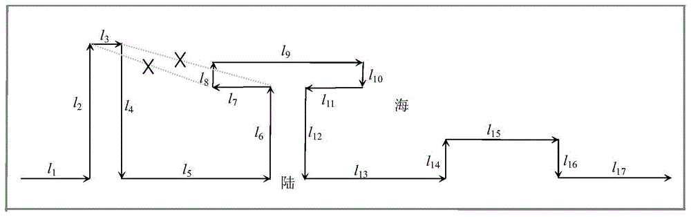
图2是本发明实施例中人工海岸线构成的示意图;2 is a schematic diagram of an artificial coastline in an embodiment of the present invention;
图3是本发明实施例中构成突出式海岸人工建筑的平行组的示意图;3 is a schematic diagram of a parallel group constituting a protruding coastal artificial building in an embodiment of the present invention;
图4-a是本发明实施例中具有相接关系的有向中心线初次合并的示意图;FIG. 4-a is a schematic diagram of the initial merging of directional centerlines with a connected relationship in an embodiment of the present invention;
图4-b是本发明实施例中具有相交关系的有向中心线初次合并的示意图;FIG. 4-b is a schematic diagram of the initial merging of directional centerlines with an intersecting relationship in an embodiment of the present invention;
图4-c是本发明实施例中具有重叠关系的有向中心线初次合并的示意图;FIG. 4-c is a schematic diagram of the initial merging of directional centerlines with an overlapping relationship in an embodiment of the present invention;
图4-d是本发明实施例中具有近似重叠关系的有向中心线初次合并的示意图;4-d is a schematic diagram of the initial merging of directional centerlines with an approximate overlapping relationship in an embodiment of the present invention;
图5是本发明实施例中两有向中心线间全连接及利用全连接合并有向中心线的示意图;5 is a schematic diagram of a full connection between two directional centerlines and a combination of directional centerlines using the full connection in the embodiment of the present invention;
图6-a是本发明实施例中第一种自由点移动的示意图;6-a is a schematic diagram of the first free point movement in the embodiment of the present invention;
图6-b是本发明实施例中第二种自由点移动的示意图;Figure 6-b is a schematic diagram of the second free point movement in the embodiment of the present invention;
图6-c是本发明实施例中第三种自由点移动的示意图;Figure 6-c is a schematic diagram of the third free point movement in the embodiment of the present invention;
图6-d是本发明实施例中第四种自由点移动的示意图;6-d is a schematic diagram of the fourth free point movement in the embodiment of the present invention;
图7是本发明实施例中收缩点移动得到准确降维表达的示意图;7 is a schematic diagram of an accurate dimensionality reduction expression obtained by moving a contraction point in an embodiment of the present invention;
图8-a是本发明实施例中收缩点无需移动情况的示意图;Fig. 8-a is a schematic diagram of a situation in which the retraction point does not need to be moved in an embodiment of the present invention;
图8-b是本发明实施例中收缩点移动的示意图;Fig. 8-b is a schematic diagram of the movement of the contraction point in the embodiment of the present invention;
图9-a是本发明实施例中删除降维表达协调拓扑冲突的示意图;Fig. 9-a is a schematic diagram of deleting dimension reduction expression coordination topology conflict in an embodiment of the present invention;
图9-b是本发明实施例中移动降维表达协调拓扑冲突的示意图。FIG. 9-b is a schematic diagram illustrating a coordinated topology conflict in mobile dimensionality reduction expression in an embodiment of the present invention.
具体实施方式Detailed ways
下面结合附图对本发明的具体实施方式进行进一步地说明。The specific embodiments of the present invention will be further described below with reference to the accompanying drawings.
本发明通过识别构成突出式海岸人工建筑的平行弧段组,从中提取有向中心线,对提取出的有向中心线进行合并、自由点和收缩点移动,得到突出式海岸线人工建筑中心线,实现对突出式海岸人工建筑进行化简(降维);从除突出式海岸建筑外的剩余人工海岸线中提取海侧弯曲单元,并进行化简;对化简结果与突出式海岸线人工建筑中心线存在拓扑冲突进行处理,最终实现人工海岸线的自动化简。整个化简过程,不仅确保了化简结果符合目标尺度下制图要求,还保持了丰富、准确的人工海岸特征,解决了现有人工海岸线化简方法导致的形态失真问题。The invention obtains the center line of the protruding coastline artificial building by identifying the parallel arc segment group constituting the protruding coastal artificial building, extracting the directional centerline therefrom, merging the extracted directional centerline, moving the free point and the shrinking point, and obtaining the protruding coastline artificial building centerline. Realize the simplification (dimension reduction) of the protruding coastal artificial buildings; extract the seaside curved elements from the remaining artificial coastlines except the protruding coastal buildings, and perform the simplification; There are topological conflicts to deal with, and finally realize the automation of artificial coastlines. The whole simplification process not only ensures that the simplification results meet the mapping requirements at the target scale, but also maintains the rich and accurate characteristics of the artificial coastline, and solves the problem of morphological distortion caused by the existing artificial coastline simplification methods.
本发明人工海岸线化简方法的实施例The embodiment of the artificial coastline simplification method of the present invention
为方便表述,作如下定义:For convenience, the following definitions are made:
定义l的起始顶点记为l_f,终止顶点记为l_t。l为l对应的向量,|l|=l,l的方向是从l的起始顶点指向终止顶点的方向,顶点va向顶点vb的连线记为dl(va,vb),线要素l的长度记为Len(l);Define the starting vertex of l as l_f and the ending vertex as l_t. l is the vector corresponding to l, |l|=l, the direction of l is the direction from the start vertex of l to the end vertex, and the connection line from vertex v a to vertex v b is denoted as dl(va , v b ) , The length of the line element l is recorded as Len(l);
某条人工海岸线的有序顶点依次为v1、…、vn,顶点序号递增方向定义为该条海岸线的方向,L内相邻顶点vi-1、vi构成的向量
定义函数Ang(li,lj)用于计算li到lj的角度,设α为近似共线的角度阈值,β为近似平行的角度阈值。The function Ang(l i ,l j ) is defined to calculate the angle from l i to l j , where α is an approximately collinear angle threshold, and β is an approximately parallel angle threshold.
有向中心线lm对应的平行组弧段记为pl(lm)1和pl(lm)2,规定对应有序集合{lx}中,pl(lm)1先于pl(lm)2;The parallel group arcs corresponding to the directional centerline l m are denoted as pl(l m ) 1 and pl(l m ) 2 , and it is stipulated that in the corresponding ordered set {l x }, pl(l m ) 1 precedes pl(l m ) 2 ;
lm、lm+1端点间的全连接记为CC(lm,lm+1)={dl(lm_f,lm+1_f),dl(lm_f,lm+1_t),dl(lm_t,lm+1_f),dl(lm_t,lm+1_t)},CC(lm,lm+1)中距离最大的连接记为Max{CC(lm,lm+1)}。The full connection between lm and lm +1 endpoints is denoted as CC(lm , lm +1 )= { dl(lm _f , lm +1 _f ), dl(lm _f, lm +1 _t ), dl(l m _t,l m+1 _f),dl(l m _t,l m+1 _t)}, the connection with the largest distance in CC(l m ,l m+1 ) is recorded as Max{CC( l m ,l m+1 )}.
化简前后比例尺分别记为S1、S2,图上最小可视距离记为svo,线宽记为b。thl表示突出式人工建筑半依比例尺表达形式的长度阈值,thw表示图上线划间宽度阈值,thb表示图上弯曲基线阈值,ths表示图上弯曲面积阈值。通常情况下,thl=1mm,thw=2·b+svo,thb=2·(b+svo),ths=thb2,svo=0.2mm,b=0.1mm。The scales before and after the simplification are respectively recorded as S 1 and S 2 , the minimum visible distance on the figure is recorded as svo, and the line width is recorded as b. thl represents the length threshold of the semi-scaled representation of the protruding artificial buildings, thw represents the width threshold between the lines on the map, thb represents the curve baseline threshold on the map, and ths represents the curve area threshold on the map. Normally, thl=1mm, thw=2·b+svo, thb=2·(b+svo), ths=thb2, svo=0.2mm, b=0.1mm.
下面以图2中的人工海岸线为例对本发明的化简方法进行详细说明,该方法的具体实现过程如下。The simplification method of the present invention will be described in detail below by taking the artificial coastline in FIG. 2 as an example, and the specific implementation process of the method is as follows.
1.人工海岸线描述。1. Description of the artificial coastline.
以顶点递增方向为人工海岸线方向,确保人工海岸线方向一侧为海洋,另一侧为陆地,将人工海岸线描述成相邻顶点构成的有向弧段集合。Taking the increasing direction of the vertices as the direction of the artificial coastline to ensure that one side of the artificial coastline is the ocean and the other side is the land, and the artificial coastline is described as a set of directed arcs composed of adjacent vertices.
1.1定义顶点递增方向为岸线方向,如图2所示,多引桥的人工建筑的存在使得人工海岸线由岸线主体(L)和闭合环(L')构成,更改与L方向相同的L',使其方向与L相反。确保沿岸线方向一侧为海洋,另一侧为陆地,其中,L'也可为空。本实施例而言,如图2所示,该人工海岸线的有序顶点依次为v1、…、vn,顶点序号递增方为人工海岸线的方向为从左至右将L与L'离散成相邻顶点构成的有向弧段(相邻顶点vi-1、vi构成的向量
1.2为避免各有向弧段存在冗余点、假转折点的干扰,还需将有向弧段集合中的多段邻接且近似共线的li合并成lk,其中L、L'中邻接且近似共线向量合并后的有向弧段集合分别记为{lk}、{lk’}。其中,近似共线指的是两个有向弧段的夹角小于α,α为近似共线的角度阈值,一般情况下0°≤α≤10;当li到li+1的角度不大于α时,则二者邻接且近似共线,需要将其合并。1.2 In order to avoid the interference of redundant points and false turning points in each directional arc segment, it is also necessary to combine multiple adjacent and approximately collinear li in the set of directional arcs into lk , where L and L' are adjacent and The set of directed arc segments after the combination of approximately collinear vectors is denoted as {l k } and {l k' } respectively. Among them, the approximate collinearity refers to the angle between the two directional arc segments is less than α, α is the approximate collinear angle threshold, generally 0°≤α≤10; when the angle from l i to l i+1 is not When it is greater than α, the two are adjacent and approximately collinear, and they need to be merged.
步骤1通过计算机实现的过程如下:The process of
Step1:若存在与L同向的L',则更新L'内各个顶点下标,令i=n-i+1,重复此步骤;否则,对L及所有L'依次执行Step2;Step1: If there is L' in the same direction as L, update the subscripts of each vertex in L', let i=n-i+1, and repeat this step; otherwise, perform Step2 for L and all L's in turn;
Step2:若i=n(或i'=n'),则此L(或L')预处理结束;若i<n(或i'<n',令i=i',n=n'),则执行Step3;Step2: If i=n (or i'=n'), then this L (or L') preprocessing ends; if i<n (or i'<n', let i=i', n=n') , then execute Step3;
Step3:若Ang(li,li+1)>α,则令lk=li,i=i+1,执行Step2;若Ang(li,li+1)≤α,则li与li+1近似共线,新建链表List,li与li+1加入List,执行Step4;Step3: If Ang(l i ,l i+1 )>α, then set l k =l i , i=i+1, and execute Step2; if Ang(l i ,l i+1 )≤α, then l i Approximately collinear with l i+1 , create a new linked list List, add l i and l i+1 to the List, and execute Step4;
Step4:若不存在Ang(lj,li+2)≤α(其中lj∈List),则li+2加入List,令i=i+1,重复Step4;若存在Ang(lj,li+2)>α或i+2=n,令lk=List,则lk即为近似共线的弧段,令i=i+2,转入Step2。Step4: If there is no Ang(l j ,l i+2 )≤α(where l j ∈List), then l i+2 is added to List, let i=i+1, repeat Step4; if there is Ang(l j , l i+2 )>α or i+2=n, let l k =List, then l k is the approximately collinear arc segment, let i=i+2, go to Step2.
L预处理后,被依次划分为有序弧段集合{lk},其中1≤k≤u;所有L'预处理后划分的弧段集合依次存入弧段集合{lk’},其中1≤k'≤u';lx∈{lk}或{lk'},顶点按原线对应顶点序号递增的顺序存储,lx方向与原线方向一致,lx为由lx首顶点向末顶点连结成的向量。After L preprocessing, it is divided into ordered arc set {l k }, where 1≤k≤u; all arc sets divided by L' after preprocessing are sequentially stored in arc set {l k' }, where 1≤k'≤u'; l x ∈{l k } or {l k' }, the vertices are stored in the order of increasing vertex numbers corresponding to the original line, the direction of l x is the same as the direction of the original line, and l x is the first line from l x . A vector connecting the vertices to the end vertex.
2.提取有向中心线。2. Extract the directed centerline.
2.1识别平行弧段组。2.1 Identify groups of parallel arc segments.
识别预处理后的人工海岸线中构成突出式海岸人工建筑的一组平行或近似平行的弧段,称为平行弧段组,构成突出式海岸人工建筑的平行弧段组应满足以下条件:1)平行组内的两弧段平行或近似平行;2)平行组间只包含陆地,不包括海洋;3)平行组的两弧段间间距小于两弧段的平均长度。Identify a group of parallel or approximately parallel arc segments that constitute a protruding coastal artificial building in the preprocessed artificial coastline, which is called a parallel arc segment group. The parallel arc segment group that constitutes a protruding coastal artificial building should meet the following conditions: 1) The two arcs in the parallel group are parallel or approximately parallel; 2) The parallel group only contains land, excluding the ocean; 3) The distance between the two arcs in the parallel group is less than the average length of the two arcs.
对本实施例而言,如图3所示,l3与l7平行,满足条件1),但不满足条件2)、3),不能构成平行弧段组;l14与l16满足条件1)、2),但不满足条件3),二者间距较大,对应顺岸式人工建筑,也不是构成突出式海岸人工建筑的平行组。其中,l2与l4、l6与l12、l7与l9、l9与l11都是构成突出式海岸人工建筑的平行弧段组。For this embodiment, as shown in FIG. 3 , l3 and l7 are parallel and satisfy condition 1 ), but do not satisfy conditions 2) and 3), and cannot form a parallel arc segment group; l14 and l16 satisfy condition 1) , 2), but do not meet the condition 3), the distance between the two is relatively large, which corresponds to the coastal artificial buildings, and is not a parallel group that constitutes the protruding coastal artificial buildings. Among them, l 2 and l 4 , l 6 and l 12 , l 7 and l 9 , l 9 and l 11 are all parallel arc segments that constitute the protruding coastal artificial buildings.
该步骤通过计算机实现的过程如下:The computer-implemented process of this step is as follows:
根据前述原理,针对构成突出式海岸人工建筑的平行组的三个条件构造三个函数F1()~F3(),用于平行组的识别。According to the aforementioned principles, three functions F 1 ( ) to F 3 ( ) are constructed for the three conditions constituting the parallel groups of the protruding coastal artificial structures, which are used for the identification of the parallel groups.
F1(lp,lq):若β<Ang(lp,lq)≤180°,170°≤β≤180°,则返回True;否则,返回False。F 1 (l p ,l q ): If β<Ang(l p ,l q )≤180°, 170°≤β≤180°, return True; otherwise, return False.
F2(lp,lq):构建辅助线dl(lp_f,lq_t)和dl(lp_t,lq_f),若两辅助线均包含于陆地内,则返回True;否则,返回False。F 2 (l p ,l q ): construct auxiliary lines dl(l p _f,l q _t) and dl(l p _t,l q _f), if both auxiliary lines are included in the land, return True; otherwise , which returns False.
F3(lp,lq):dl(lp_f,lq_t)中点和dl(lp_t,lq_f)中点连结的线段为lm。对于近似平行的lp和lq:对应的lm为lp和lq的中位线,Len(lm)为lp和lq的平均长度;lp、dl(lp_f,lq_t)、lq、dl(lp_t,lq_f)所围成近似梯形的多边形,面积为S;lp与lq为该梯形的平行边,二者间平均距离dis(lp,lq)可以看作此梯形的高,由dis(lp,lq)=S/Len(lm)求出;若dis(lp,lq)<Len(lm),则返回lm,|lm|=lm,lm方向与lp一致,lm称为有向中心线;否则,返回Null。F 3 ( lp ,l q ): The line segment connecting the midpoint of dl(l p _f,l q _t) and the midpoint of dl(l p _t,l q _f ) is lm . For approximately parallel l p and l q : the corresponding l m is the median line of l p and l q , Len(l m ) is the average length of l p and l q ; l p , dl(l p _f,l q _t), l q , dl(l p _t,l q _f) form an approximate trapezoidal polygon with area S; l p and l q are the parallel sides of the trapezoid, and the average distance between them is dis(l p ,l q ) can be regarded as the height of this trapezoid, which is obtained by dis(l p ,l q )=S/Len(l m ); if dis(l p ,l q )<Len(l m ), return l m , |l m |=l m , the direction of l m is consistent with l p , and l m is called the directional centerline; otherwise, return Null.
2.2提取有向中心线:2.2 Extract the directed centerline:
平行弧段组内两弧段间的中心线段(平行弧段组内不同弧段的起止顶点连线中点所连结而成的线段)即为有向中心线段,有向中心线lm对应的平行组弧段记为pl(lm)1和pl(lm)2,规定对应有序集合{lx}中,pl(lm)1先于pl(lm)2;有向中心线只有起始顶点(标记为收缩点)和终止顶点(标记为自由点)两个顶点,起始顶点向终止顶点的方向即为该有向中心线的方向,该有向中心线是构成突出式海岸人工建筑中心线的基本单元。The center line segment between two arc segments in the parallel arc segment group (the line segment formed by connecting the midpoints of the starting and ending vertices of different arc segments in the parallel arc segment group) is the directional center line segment, and the directional center line lm corresponds to The parallel group arcs are denoted as pl(l m ) 1 and pl(l m ) 2 , which specify that in the corresponding ordered set {l x }, pl(l m ) 1 precedes pl(l m ) 2 ; There are only two vertices, the starting vertex (marked as a shrinking point) and the ending vertex (marked as a free point), and the direction from the starting vertex to the terminal vertex is the direction of the directional centerline, which constitutes a protruding type The basic unit of the centerline of the coastal artificial building.
通过计算机手段的提取过程为:The extraction process by computer means is as follows:
从{lk}中l1开始,按如下步骤探测L内、L与L'间的平行组弧段,并依次得到平行组对应的有向中心线集合{lm}。Starting from l 1 in {l k }, the parallel group arcs in L and between L and L' are detected as follows, and the directional centerline sets {l m } corresponding to the parallel groups are obtained in turn.
Step1:若u>2时,则执行下一步;若u=1且u'>0,则执行Step5;若u=1且u'=0,终止;若u=0,则终止;Step1: If u>2, execute the next step; if u=1 and u'>0, execute Step5; if u=1 and u'=0, terminate; if u=0, terminate;
Step2:生成计步器y,令y=2。顾及地理学第一定律,避免计算量过大,可以规定步数阈值为常量thr;Step2: Generate pedometer y, let y=2. Taking into account the first law of geography, to avoid excessive calculation, the threshold of the number of steps can be specified as a constant thr;
Step3:若F1(l1,l1+y)=True且F2(l1,l1+y)=True且F3(l1,l1+y)≠Null,则l1和l1+y为一组平行组弧段,将F3(l1,l1+y)返回的lm加入集合{lm},将l1从{lk}中移除后,执行Step1;否则,执行下一步;Step3: If F 1 (l 1 ,l 1+y )=True and F 2 (l 1 ,l 1+y )=True and F 3 (l 1 ,l 1+y )≠Null, then l 1 and l 1+y is a set of parallel arc segments, add lm returned by F 3 (l 1 ,l 1+y ) to the set {l m }, remove l 1 from { l k } , and execute Step1; Otherwise, go to the next step;
Step4:若y<thr,则令y=y+1,重复Step3;否则,执行下一步;Step4: If y<thr, set y=y+1, repeat Step3; otherwise, go to the next step;
Step5:遍历{lk'},若存在lk’使得F1(l1,lk')=True且F2(l1,lk')=True且F3(l1,lk')≠Null,则l1和lk'构成一个平行组,将F3(l1,lk')返回的lm加入集合{lm},将对应lk'移除,l1也从{lk}中移除,执行Step1;否则,将l1从{lk}中移除后执行Step1。Step5: Traverse {l k' }, if there is l k' such that F 1 (l 1 ,l k' )=True and F 2 (l 1 ,l k' )=True and F 3 (l 1 ,l k' )≠Null, then l 1 and l k' form a parallel group, add l m returned by F 3 (l 1 ,l k' ) to the set {l m }, remove the corresponding l k' , and l 1 also changes from Remove from {l k } and execute Step1; otherwise, remove l 1 from { lk } and execute Step1.
类似的,重复以上步骤再探测剩余{lk'}内的平行组及其对应的有向中心线,初步得到有向中心线集合{lm}。Similarly, repeat the above steps to detect the parallel groups in the remaining { lk' } and their corresponding directional centerlines, and initially obtain a set of directional centerlines {1 m }.
按如下步骤确定有向中心线方向,得到最终的有向中心线集合{lm}。Determine the direction of the directional centerline according to the following steps, and obtain the final set of directional centerlines {l m }.
Step1:将所有lm方向确定为与pl(lm)1方向一致:若Ang(lj,li+2)≤90°,则lm方向与pl(lm)1方向一致;否则,交换lm的端点,改变方向;执行下一步;Step1: Determine all the lm directions to be consistent with the pl(l m ) 1 directions: if Ang(l j ,l i +2 )≤90°, then the l m directions are consistent with the pl(l m ) 1 directions; otherwise, Swap the endpoints of l m , change direction; go to the next step;
Step2:依次判断所有lm对应的平行组弧段是否与L'相离,若均相离,则终止;否则,执行下一步;Step2: Judge in turn whether all parallel group arcs corresponding to lm are separated from L', if they are separated, terminate; otherwise, go to the next step;
Step3:若存在lm对应的平行组弧段与L'中闭合环不相离,则lm与对应闭合环相关。Step3: If there is a parallel group arc segment corresponding to lm that is not separated from the closed loop in L', then lm is related to the corresponding closed loop.
3.有向中心线初次合并。3. Directional centerline initial merge.
3.1若两连续的有向中心线有且只有一个公共顶点,即二者相接,则将公共顶点作为连接点直接将二者合并,初次合并后的中心线的起止顶点的标记与合并前有向中心线端点的标记一致,示意过程如图4-a所示。3.1 If two consecutive directional centerlines have and only one common vertex, that is, they are connected, then the common vertex is used as the connection point to directly merge the two. The markings towards the end points of the center line are the same, and the schematic process is shown in Figure 4-a.
3.2若两连续的有向中心线具有相交、重叠或近似重叠的的关系,有两向中心线进行全连接(即两有向中心间所有顶点间进行连接),并选择全连接中最长的线段作为初次合并的结果,实现初次合并,初次合并后的中心线的起止顶点的标记与合并前有向中心线端点的标记一致。3.2 If two consecutive directional centerlines have a relationship of intersecting, overlapping or approximately overlapping, there are two-directional centerlines for full connection (that is, all vertices between the two directional centers are connected), and the longest of the full connections is selected. As the result of the initial merging, the line segments are merged for the first time, and the marks of the starting and ending vertices of the center lines after the initial merging are consistent with the marks of the end points of the directional center lines before the merging.
相交指的是两连续的有向中心线有且只有一个交点且交点不是公共顶点,则二者相交;重叠指的是两连续的有向中心线间包含重叠弧段,则二者重叠;近似重叠指的是两连续的有向中心线的全连接均包含于海岸线陆地一侧,则二者进行重叠,具有相交、重叠、近似重叠关系两有向中心线初次合并的示意过程分别如图4-b、图4-c、图4-d所示。其原理如图5所示,获取两有向中心线全连接,并从中选取最长的线段作为合并结果。Intersection means that two consecutive directional centerlines have one and only one intersection point and the intersection point is not a common vertex, then the two intersect; overlap means that two consecutive directional centerlines contain overlapping arcs, then the two overlap; approximately Overlapping means that the full connection of two continuous directional centerlines is included on the land side of the coastline, then the two overlap, with intersecting, overlapping, and approximately overlapping relationships. The schematic process of the initial merging of the two directional centerlines is shown in Figure 4. -b, Figure 4-c, Figure 4-d. The principle is shown in Figure 5. Two directional center lines are fully connected, and the longest line segment is selected as the merged result.
初次合并后的中心线(包含未参加合并的有向中心线)的端点只存在两种标记情况:端点均被标记为自由点(终止顶点)、一个端点被标记为自由点和一个端点被标记为收缩点(起始顶点)。There are only two marked cases for the endpoints of the centerlines after the initial merge (including the directional centerlines that did not participate in the merge): the endpoints are marked as free points (terminal vertices), one endpoint is marked as a free point, and one endpoint is marked is the contraction point (starting vertex).
通过计算机的实现手段为:The means of realization through the computer are:
Step1:新建集合List{}用于存储待合并的有向中心线,将lm加入到List{},执行下一步。Step1: Create a new set List{} to store the directional centerlines to be merged, add l m to List{}, and execute the next step.
Step2:若lm与lm+1有公共顶点,lm+1加入List{},令m=m+1,重复此步骤;若lm与lm+1无公共顶点,执行下一步。Step2: If lm and lm +1 have a common vertex, add lm +1 to List{}, let m = m +1, and repeat this step; if lm and lm +1 have no common vertex, go to the next step.
Step3:若lm与lm+1有且只有一个交点,且交点不是公共顶点,则令lm=Max{CC(lm,lm+1)}且lm+1=Max{CC(lm,lm+1)},更新List{}中的lm,令m=m+1,执行Step2;否则,执行下一步。Step3: If lm and lm +1 have one and only one intersection, and the intersection is not a common vertex, then let lm =Max { CC( lm ,lm +1 )} and lm +1 =Max { CC( lm , lm +1 )}, update lm in List{}, let m = m +1, execute Step2; otherwise, execute the next step.
Step4:若lm与lm+1存在重叠部分,则令lm=Max{CC(lm,lm+1)}且lm+1=Max{CC(lm,lm+1)},更新List{}中的lm,令m=m+1,执行Step2;否则,执行下一步。Step4: If there is an overlap between lm and lm +1 , then let lm =Max { CC( lm ,lm +1 )} and lm +1 =Max { CC( lm ,lm +1 ) }, update lm in List{}, let m= m +1, execute Step2; otherwise, execute the next step.
Step5:若CC(lm,lm+1)均包含于海岸线陆地侧,则令lm=Max{CC(lm,lm+1)}且lm+1=Max{CC(lm,lm+1)},更新List{}中的lm,令m=m+1,执行Step2;否则,执行下一步。Step5: If CC(lm , lm +1 ) are all included on the land side of the coastline, then let lm =Max { CC( lm ,lm +1 )} and lm +1 =Max { CC( lm +1) , lm +1 )}, update lm in List{}, let m =m+1, execute Step2; otherwise, execute the next step.
Step6:若List{}中包含不止一个元素,则以公共顶点作为连接点,得到初次合并的中心线;否则,List{}中的唯一元素即为初次合并后的中心线。令m=m+1,执行Step1。Step6: If the List{} contains more than one element, use the common vertex as the connection point to obtain the center line of the initial merge; otherwise, the only element in the List{} is the center line after the initial merge. Let m=m+1, and execute Step1.
初次合并后的中心线集合记为{lm'},lm'端点的标记与合并前有向中心线起止顶点标记相同。The centerline set after the initial merging is denoted as {l m' }, and the marking of the end point of lm ' is the same as the marking of the starting and ending vertices of the directional centerline before the merging.
4.对初次合并后的有向中心线进行端点移动。4. Perform the end point movement on the directional centerline after the initial merging.
4.1自由点移动4.1 Free point movement
被标记为自由点的端点的移动方式如下:Endpoints marked as free points are moved as follows:
1)自由点向邻近的初次合并的中心线的收缩点移动,并以此移动轨迹作为连结线段,与相邻的中心线合并,如图6-a所示;1) The free point moves to the shrinking point of the adjacent initial merged center line, and uses this movement trajectory as the connecting line segment to merge with the adjacent center line, as shown in Figure 6-a;
2)自由点沿初次合并的中心线内移动至与海岸线交点处停止,如图6-b所示;2) The free point moves along the center line of the initial merger and stops at the intersection with the coastline, as shown in Figure 6-b;
3)自由点沿初次合并的中心线延长线方向移动至与海岸线交点处停止,如图6-c所示;3) The free point moves in the direction of the extension line of the center line of the initial merger and stops at the intersection with the coastline, as shown in Figure 6-c;
4)自由点沿初次合并的中心线延长线方向移动至另一中心线终止,且以此移动轨迹作为连结线段,合并两中心线,如图6-d所示。4) The free point moves in the direction of the extension line of the first merged center line to the end of another center line, and uses this movement trajectory as the connecting line segment to merge the two center lines, as shown in Figure 6-d.
自由点移动后,中心线合并完成,合并后的中心线对应的平行弧段组中下标最小的顶点与最大的顶点间所夹的弧段即为初步识别的突出式海岸人工建筑。自由点移动过程中伴随有有向中心线的再次合并。通过计算机的实现过程为:After the free point is moved, the centerline is merged, and the arc segment between the vertex with the smallest subscript and the largest vertex in the parallel arc segment group corresponding to the merged centerline is the preliminarily identified protruding coastal artificial building. The movement of the free point is accompanied by the re-merging of the directional centerlines. The realization process through the computer is:
Step1:若lm'自由点与l(m±1)'收缩点连线位于陆侧,且是CC(lm',l(m±1)')中包含于陆地一侧连结中距离最小的,则连接lm'自由点与l(m±1)'收缩点,且合并lm'与l(m±1)';否则,执行下一步;Step1: If the line connecting the l m' free point and the l (m±1)' shrinkage point is located on the land side, and is the smallest distance in the connection on the land side included in CC(l m' ,l (m±1)' ) , then connect the lm ' free point and the l (m±1)' contraction point, and merge lm ' and l (m±1)' ; otherwise, go to the next step;
Step2:若lm'与L相交,则自由点沿lm'向内移动至lm'与L的交点处,终止移动;否则,执行下一步;Step2: If lm ' and L intersect, the free point moves inward along lm ' to the intersection of lm ' and L to terminate the movement; otherwise, execute the next step;
Step3:自由点沿lm'延长线向外移动,若与l(m±1)'相交,则终止移动,执行下一步;否则,自由点沿lm'延长线向外移动,直至与L相交,终止;Step3: The free point moves outward along the extension line of lm ' . If it intersects with l (m±1)' , the movement is terminated and the next step is executed; otherwise, the free point moves outward along the extension line of lm ' until it intersects with L intersect, terminate;
Step4:若交点是l(m±1)'的端点或l(m±1)'中不含收缩点,则合并lm'与l(m±1)'即可;若交点不是l(m±1)'的端点且l(m±1)'包含收缩点,则l(m±1)'收缩点沿l(m±1)'向内移动至交点时终止,且合并lm'与l(m±1)'。Step4: If the intersection point is the end point of l (m±1)' or l (m±1)' does not contain a shrinkage point, then merge l m' and l (m±1)' ; if the intersection point is not l ( m±1)'±1)' end point and l (m±1)' includes the contraction point, then the l (m ± 1)' contraction point moves inward along l (m ± 1)' to the intersection and terminates, and merges l m' and l (m±1)' .
4.2收缩点移动4.2 Contraction point movement
自由点移动引发合并后的中心线集合记为{lm”},lm”对应一个初步识别的、独立的突出式人工建筑的中心线。在此基础上,还要通过移动收缩点,如图7所示,处理合并后的中心线lm”,得到最终的中心线结果。The merged centerline set caused by the movement of the free point is denoted as {l m” }, where lm ” corresponds to the centerline of a preliminarily identified and independent protruding artificial building. On this basis, by moving the shrinkage point, as shown in Figure 7, the merged centerline lm " is processed to obtain the final centerline result.
其中包含收缩点的有向中心线记为lm_s,其对应平行组的弧段分别为pl(lm_s)1和pl(lm_s)2,预处理后的人工海岸线中包含pl(lm_s)1起始顶点且不是pl(lm_s)1的弧段记为lk1,包含pl(lm_s)2终止顶点且不是pl(lm_s)2的弧段记为lk2,lk1-2为pl(lm_s)1起始顶点与pl(lm_s)2终止顶点连结的线段。收缩点在以下两种情况下无需移动,如图8-a所示,图8-a中的图例与图8-b中的一样。The directional centerline including the shrinkage point is denoted as lm_s , and the arcs corresponding to the parallel groups are respectively pl(l m_s ) 1 and pl(l m_s ) 2 , and the preprocessed artificial coastline contains pl(l m_s ) 1 starting vertex and not pl(l m_s ) 1 arc segment is denoted as l k1 , including pl(l m_s ) 2 ending vertex and not pl(l m_s ) 2 arc segment is denoted as l k2 , l k1-2 is pl(l m_s ) 1 is the line segment connecting the starting vertex and pl(l m_s ) 2 ending vertex. The contraction point does not need to move in the following two cases, as shown in Fig. 8-a, and the legend in Fig. 8-a is the same as that in Fig. 8-b.
1)lk1、lk2及lk1-2近似共线,收缩点不移动;1) l k1 , l k2 and l k1-2 are approximately collinear, and the contraction point does not move;
2)lk1、lk2及lk1-2不近似共线时,若沿lk1方向延长交于pl(lm_s)2的延长线且沿lk2反向延长交于pl(lm_s)1的延长线,或沿lk1方向延长交于pl(lm_s)2内且沿lk2反向延长交于pl(lm_s)1内,也不用移动收缩点。2) When l k1 , l k2 and l k1-2 are not approximately collinear, if it is extended along the direction of l k1 to the extension line of pl(l m_s ) 2 and extended in the reverse direction of l k2 to meet pl(l m_s ) 1 The extension line of , or extending along the direction of l k1 and intersecting in pl(l m_s ) 2 and extending in the reverse direction of l k2 and intersecting in pl(l m_s ) 1 , without moving the contraction point.
当不满足上述两种情况时,收缩点沿有向中心线方向移动至与该有向中心线的交点位置,并向初步识别的突出式海岸人工建筑中插入新定点用于更新对应平行组弧段的起始(或终止)顶点,进而对突出式海岸建筑识别结果进行更新,得到最终识别结果,其过程如图8-b所示。通过计算机实现收缩点移动的具体过程为:When the above two conditions are not satisfied, the shrinking point is moved to the intersection with the directional centerline along the direction of the directional centerline, and a new fixed point is inserted into the preliminarily identified protruding coastal artificial building for updating the corresponding parallel group arc The starting (or ending) vertex of the segment is updated, and the recognition result of the protruding coastal building is updated to obtain the final recognition result. The process is shown in Figure 8-b. The specific process of realizing the movement of the contraction point through the computer is as follows:
Step1:连结pl(lm_s)1_f和pl(lm_s)2_t得到dl(pl(lm_s)1_f,pl(lm_s)2_t),若Ang(lk1,dl(pl(lm_s)1_f,pl(lm_s)2_t))≤α且Ang(dl(pl(lm_s)1_f,pl(lm_s)2_t),lk2)≤α,即lk1、dl(pl(lm_s)1_f,pl(lm_s)2_t)、lk2近似共线,则不做处理;否则,执行下一步;Step1: Connect pl(l m_s ) 1 _f and pl(l m_s ) 2 _t to get dl(pl(l m_s ) 1 _f,pl(l m_s ) 2 _t), if Ang(l k1 ,dl(pl(l m_s ) ) 1 _f,pl(l m_s ) 2 _t))≤α and Ang(dl(pl(l m_s ) 1 _f,pl(l m_s ) 2 _t),l k2 )≤α, that is, l k1 , dl(pl (l m_s ) 1 _f, pl(l m_s ) 2 _t), l k2 are approximately collinear, then do not process; otherwise, go to the next step;
Step2:若沿lk1方向延长交于pl(lm_s)2的延长线且沿lk2反向延长交于pl(lm_s)1的延长线,或沿lk1方向延长交于pl(lm_s)2内且沿lk2反向延长交于pl(lm_s)1内,则不做处理;否则,执行下一步;Step2: If the extension line that intersects pl(l m_s ) 2 is extended in the direction of l k1 and the extension line that intersects pl(l m_s ) 1 is extended in the reverse direction of l k2 , or the extension line that intersects pl(l m_s ) is extended in the direction of l k1 ) 2 and extended in the reverse direction along l k2 and intersected in pl(l m_s ) 1 , then no processing is performed; otherwise, the next step is performed;
Step3:沿lk1方向(或lk2反向)延长交于pl(lm_s)2(或pl(lm_s)1)内,交点作为L中新插入的顶点记为vm_i,且沿lk2反向(或lk1方向)延长交于pl(lm_s)1反向延长线(或pl(lm_s)2延长线)上,将lm_s收缩点移动至lm_s与dl(pl(lm_s)1_f,vm_i)(或dl(pl(lm_s)2_t,vm_i))的交点,则改变原中心线。将pl(lm_s)2_t(或pl(lm_s)1_f)替换为vm_i,对应平行组的弧段也得到处理。Step3: Extend and intersect in pl(l m_s ) 2 (or pl(l m_s ) 1 ) along the direction of l k1 (or the reverse of l k2 ), and the intersection is recorded as a newly inserted vertex in L as v m_i , and along l k2 Reverse (or l k1 direction) extension and intersect on the pl(l m_s ) 1 reverse extension line (or pl(l m_s ) 2 extension line), move the l m_s contraction point to l m_s and dl(pl(l m_s ) 1 _f, v m_i ) (or dl(pl(l m_s ) 2 _t, v m_i )), then change the original center line. By replacing pl(l m_s ) 2 _t (or pl(l m_s ) 1 _f) with v m_i , the arcs corresponding to the parallel groups are also processed.
有向中心线合并过程中,对应的平行组加入同一集合;处理后得到最终中心线lm”'及其对应的平行组集合;获取平行组集合中所有线要素端点对应于L中顶点的下标,下标最小值与最大值顶点记为vm_min、vm_max,L中vm_min、vm_max及其间所有顶点构成lm”’对应的突出式人工建筑岸线。In the process of merging the directional centerlines, the corresponding parallel groups are added to the same set; after processing, the final centerline lm "' and its corresponding parallel group set are obtained; the endpoints of all line elements in the parallel group set corresponding to the lower points of the vertices in L are obtained. The vertices with the minimum and maximum subscripts are marked as vm_min and vm_max . In L, vm_min , vm_max and all the vertices in between constitute the protruding artificial building shoreline corresponding to lm "' .
5.突出式海岸人工建筑化简。5. The protruding coastal artificial buildings are simplified.
突出式海岸人工建筑中所有平行组内最小距离小于制图要求的宽度阈值时,将通过上述过程提取的有向中心线作为该突出式人工建筑的降维表达,实现降维处理;当降维表达后的突出式海岸人工建筑存在小于制图要求长度阈值的部分,则删除此突出式人工建筑。When the minimum distance in all parallel groups in the protruding coastal artificial building is less than the width threshold required for drawing, the directional centerline extracted through the above process is used as the dimensionality reduction expression of the protruding artificial building to realize dimensionality reduction processing; when the dimensionality reduction expression If there is a part of the protruding coastal artificial building that is smaller than the length threshold required for drawing, the protruding artificial building will be deleted.
提取的突出式人工建筑岸线集合记为{LT},其余部分岸线依次记为{LS},LT与LS交替出现。一般情况下突出式人工建筑间相互独立,化简处理互不影响,{LT}化简只考虑LT化简即可。The set of extracted protruding artificial building shorelines is denoted as {L T }, and the rest of the shorelines are denoted as {L S } in turn, and L T and L S appear alternately. Under normal circumstances, the protruding artificial buildings are independent of each other, and the simplification processing does not affect each other. The simplification of {L T } only considers the simplification of L T.
LT的端点分别为vm_min、vm_max,LT对应中心线为lm”',lm”'由有向中心线集合{lm}构成,lm”'对应平行组集合{{pl(lm)1,pl(lm)2}},pl(lm)1与pl(lm)2间的最小距离为dis_min(pl(lm)1,pl(lm)2)。通常情况下,thl=1mm,b=0.1mm。The endpoints of LT are vm_min and vm_max respectively. The center line corresponding to LT is lm "' , lm "' is composed of the set of directional centerlines { lm}, and lm "' corresponds to the set of parallel groups {{pl (l m ) 1 , pl(l m ) 2 }}, the minimum distance between pl(l m ) 1 and pl(l m ) 2 is dis_min(pl(l m ) 1 , pl(l m ) 2 ). Normally, thl=1mm, b=0.1mm.
dis_min(pl(lm)1,pl(lm)2)dis_min(pl(lm) 1 ,pl(lm) 2 )
=Min{Dis(pl(lm)1_f,pl(lm)2),Dis(pl(lm)1_t,pl(lm)2),Dis(pl(lm)2_f,pl(lm)1),Dis(pl(lm)2_t,pl(lm)1}=Min{Dis(pl(lm) 1 _f,pl(lm) 2 ),Dis(pl(lm) 1 _t,pl(lm) 2 ),Dis(pl(lm) 2 _f,pl(lm) 1 ) ,Dis(pl(lm) 2 _t,pl(lm) 1 }
该步骤通过计算机的实现过程为:The realization process of this step through the computer is as follows:
Step1:若Min{dis_min(pl(lm)1,pl(lm)2)}/S1≥thw/S2,则LT不做处理;否则,删除vm_min与vm_max间所有顶点,将lm”'作为LT半依比例尺的表达结果,执行Step2。Step1: If Min{dis_min(pl(l m ) 1 ,pl(l m ) 2 )}/S 1 ≥thw/S 2 , then LT does not process; otherwise, delete all vertices between vm_min and vm_max , Set lm "' as the expression result of L T semi-scale, and execute
Step2:lm””进行拓扑化处理得到{lm””}。若{lm””}数量为1时,对应突出式人工建筑为折线型,执行Step3;当{lm””}数量不为1时,对应突出式人工建筑为T型,利用垂直关系将{lm””}分为引桥集合{lm””_b}和堤岸集合{lm””_d},执行Step4。Step2: l m”” is topologically processed to obtain {l m”” }. If the number of {l m”” } is 1, the corresponding protruding artificial building is a polyline, and Step 3 is executed; when the number of {l m”” } is not 1, the corresponding protruding artificial building is T-shaped, and the vertical relationship is used to convert the {l m”” } is divided into approach bridge set {l m””_b } and embankment set {l m””_d }, execute
Step3:若Min{Len(dl(lm””_f,lm””_t)),Len(lm””)}/S1<thl/S2,则删除lm”';否则,不作处理。Step3: If Min{Len(dl(l m”” _f,l m”” _t)), Len(l m”” )}/S 1 <thl/S 2 , delete lm ”' ; otherwise, do not make deal with.
Step4:若Min{Min{Len(lm””_b)},∑{lm””_d}}/S1<thl/S2,则删除lm”';否则,不作处理。Step4: If Min{Min{Len(l m””_b )},∑{l m””_d }}/S 1 <thl/S 2 , delete lm ”' ; otherwise, do not process.
6.识别弯曲单元。6. Identify the bending element.
通过上述过程,可实现对人工海岸线中突出式海岸建筑的化简,但是人工海岸线还包括除突出式海岸建筑外的剩余人工海岸线,剩余人工海岸线形态相对规则简单,与海湾、岬角等地理要素一样均可作为一般弯曲单元进行识别、取舍。首先利用拐点法从除突出式海岸建筑外的剩余人工海岸线中识别弯曲单元,顾及“扩陆缩海”约束,提取海侧弯曲单元即可;探后通过弯曲面积、弯曲基线长度等量化衡量所识别的海侧弯曲单元,删除小于制图要求面积阈值或基线长度阈值的海侧弯曲单元;重复此识别、删除过程,直至所有不符合目标尺度下制图要求的细小海侧弯曲单元均被删除为止。Through the above process, the simplification of the protruding coastal buildings in the artificial coastline can be realized, but the artificial coastline also includes the remaining artificial coastlines except the protruding coastal buildings. The shape of the remaining artificial coastlines is relatively simple and regular, and is the same as the geographical elements such as bays and headlands. All of them can be identified and selected as general bending units. First, use the inflection point method to identify the curved elements from the remaining artificial coastlines except for the protruding coastal buildings. Taking into account the constraint of "expanding the land and shrinking the sea", it is enough to extract the curved elements on the sea side; For the identified seaside bending elements, delete the seaside bending elements smaller than the area threshold or baseline length threshold required for mapping; repeat this identification and deletion process until all the small seaside bending elements that do not meet the mapping requirements under the target scale are deleted.
对本实例而言,可采用Springer出版的第773卷CCIS中《A Progressive Methodof Simplifying Polylines with Multi-bends Simplification Templates》中改进的拐点法识别弯曲单元,若识别弯曲单元的基线(起止顶点连结的线段)包含于海洋内时,该单元为海侧单元,识别的海侧单元集合记为{U(i)}。该步骤通过计算机实现时采用的具体手段为:For this example, the improved inflection point method in "A Progressive Method of Simplifying Polylines with Multi-bends Simplification Templates" in CCIS, Volume 773, published by Springer, can be used to identify the curved element. If the baseline of the curved element (the line segment connecting the starting and ending vertices) is identified When included in the ocean, the unit is a seaside unit, and the identified seaside unit set is denoted as {U(i)}. The specific means adopted when this step is realized by computer are:
构造函数Base(U(i))返回海侧单元U(i)的基线长度;函数Area(U(i)))返回海侧单元U(i)及其基线所围成的多边形的面积。若Base(U(i))/S1<thb/S2或Area(U(i))/S1<thb/S2,则删除U(i)起止顶点间的所有顶点,即可实现该单元删除。遍历{U(i)},删除所有需要删除的海侧弯曲,得到初次的化简结果。对上一次化简后的部分重复海侧单元识别、弯曲删除,直至没有弯曲被删除为止,完成化简。The constructor Base(U(i)) returns the baseline length of the seaside unit U(i); the function Area(U(i))) returns the area of the polygon enclosed by the seaside unit U(i) and its baseline. If Base(U(i))/S 1 <thb/S 2 or Area(U(i))/S 1 <thb/S 2 , then delete all vertices between the start and end vertices of U(i) to achieve this Unit deletion. Traverse {U(i)}, delete all seaside bends that need to be deleted, and get the initial simplification result. Repeat the identification of sea-side elements and the deletion of bending for the part after the last simplification, until no bending is deleted, and the simplification is completed.
7.拓扑冲突处理。7. Topological conflict handling.
步骤5对突出式海岸人工建筑的化简和步骤6对其余人工海岸线的化简可能会产生拓扑冲突。将除突出式海岸人工建筑外的其余人工海岸线的化简结果与对应原海岸线进行叠加,已删除部分构成的面状多边形集合记为{Bm},若Bm与突出式海岸人工建筑降维表达的结果间存在重叠部分,则化简结果存在拓扑冲突。The simplification of the protruding coastal artificial buildings in step 5 and the simplification of the remaining artificial shorelines in step 6 may cause topological conflicts. The simplification results of the other artificial coastlines except the protruding coastal artificial buildings are superimposed with the corresponding original coastlines, and the set of polygonal polygons formed by the deleted part is recorded as {B m }. If B m and the protruding coastal artificial buildings are dimensionally reduced If there is an overlap between the expressed results, there is a topological conflict in the simplified results.
突出式海岸人工建筑的降维表达结果较多地包含于Bm内(降维表达结果于Bm外的部分不满足制图视觉要求)时,则将该降维表达删除,示意过程如图9-a所示。降维表达结果较少地包含于Bm内(降维表达结果于Bm外的部分足够满足制图视觉要求)时,则移动该降维表达,示意过程如图9-b所示。The dimensionality reduction expression results of the protruding coastal artificial buildings are mostly included in Bm (the part of the dimension reduction expression results outside Bm does not meet the visual requirements for mapping), the dimensionality reduction expression is deleted, and the schematic process is shown in Figure 9 -a shown. When the dimensionality reduction expression result is less included in Bm (the part of the dimensionality reduction expression result outside Bm is enough to meet the visual requirements of cartography), the dimensionality reduction expression is moved, and the schematic process is shown in Figure 9-b.
将包含于Bm内的部分记为l1m”',其余部分为l2m”'。对l1m”'、l2m”'进行拓扑化处理得到{l1m””}、{l2m””},化简前后比例尺分别记为S1、S2,图上最小可视距离记为svo,通常情况下,svo=0.2mm,lm”'与Bm的冲突处理步骤如下:Denote the part included in B m as l 1m"' and the rest as l 2m"' . Topologize l 1m"' and l 2m"' to obtain {l 1m"" }, {l 2m"" }, the scales before and after simplification are recorded as S 1 and S 2 respectively, and the minimum visible distance on the graph is recorded as svo, under normal circumstances, svo=0.2mm, and the conflict handling steps between lm "' and B m are as follows:
Step1:若l2m”'为空,则lm”'包含于Bm,直接删除lm”';否则,执行下一步;Step1: If l 2m"' is empty, then l m"' is included in B m , delete l m"' directly; otherwise, go to the next step;
Step2:若Min{Len(l2m””)}/S1<svo/S2,则删除lm”';否则,执行下一步;Step2: If Min{Len(l 2m”” )}/S 1 <svo/S 2 , delete l m”' ; otherwise, go to the next step;
Step3:Min{Len(l1m””)}记为l1m””_min,l1m””_min与lm”'有公共端点,lm”'从公共端点开始沿l1m””_min移动至l1m””_min的另一端点为止。移动结束后,若仍存在包含于Bm内的部分,则用弯曲基线截断移动后的lm”',删除包含于Bm内的部分。Step3: Min{Len(l 1m”” )} is recorded as l 1m””_min , l 1m””_min and l m”’ have a common endpoint, l m”’ starts from the common endpoint and moves along l 1m””_min to l 1m””_min to the other end point. After the movement is completed, if there is still a part included in B m , the lm "' after the movement is cut off with a curved baseline, and the part included in B m is deleted.
通过上述化简过程可知,本发明能够确保化简结果符合目标尺度下制图要求的同时,保持了丰富、准确的海岸人工特征,顾及航行安全,具有良好的拓扑一致性,是可以应用于海图综合的自动化方法。It can be seen from the above simplification process that the present invention can ensure that the simplification results meet the mapping requirements under the target scale, and at the same time maintain the rich and accurate coastal artificial features, take into account the safety of navigation, and have good topology consistency, and can be applied to nautical chart synthesis. automated method.
Claims (7)
Priority Applications (1)
| Application Number | Priority Date | Filing Date | Title |
|---|---|---|---|
| CN201910068952.XA CN109801552B (en) | 2019-01-24 | 2019-01-24 | An artificial coastline simplification method |
Applications Claiming Priority (1)
| Application Number | Priority Date | Filing Date | Title |
|---|---|---|---|
| CN201910068952.XA CN109801552B (en) | 2019-01-24 | 2019-01-24 | An artificial coastline simplification method |
Publications (2)
| Publication Number | Publication Date |
|---|---|
| CN109801552A CN109801552A (en) | 2019-05-24 |
| CN109801552B true CN109801552B (en) | 2020-11-27 |
Family
ID=66560313
Family Applications (1)
| Application Number | Title | Priority Date | Filing Date |
|---|---|---|---|
| CN201910068952.XA Active CN109801552B (en) | 2019-01-24 | 2019-01-24 | An artificial coastline simplification method |
Country Status (1)
| Country | Link |
|---|---|
| CN (1) | CN109801552B (en) |
Families Citing this family (3)
| Publication number | Priority date | Publication date | Assignee | Title |
|---|---|---|---|---|
| CN110569532B (en) * | 2019-07-19 | 2023-04-21 | 中国地质大学(武汉) | A Topological Consistency Optimization Method for Rectangle of Indoor Boundary Elements |
| CN112926465B (en) * | 2021-03-02 | 2023-04-07 | 中国人民解放军战略支援部队信息工程大学 | Coastline property identification method and device based on point cloud type |
| CN115100322B (en) * | 2022-07-23 | 2023-05-12 | 中国人民解放军战略支援部队信息工程大学 | Line element self-adaptive simplification method and device for supervised learning supported multi-reduction algorithm cooperation |
Citations (4)
| Publication number | Priority date | Publication date | Assignee | Title |
|---|---|---|---|---|
| CN101751682A (en) * | 2009-12-31 | 2010-06-23 | 武汉大学 | A method for preparing a general map |
| CN102609898A (en) * | 2012-02-09 | 2012-07-25 | 武汉大学 | Method for simplifying shoreline of drowned valley by taking geographical features into account |
| CN102708405A (en) * | 2012-04-20 | 2012-10-03 | 武汉大学 | Line feature simplification method based on clonal selection algorithm |
| CA3001119A1 (en) * | 2015-11-09 | 2017-05-18 | Landmark Graphics Corporation | Modelling complex geological sequences using geologic rules and paleographic maps |
Family Cites Families (2)
| Publication number | Priority date | Publication date | Assignee | Title |
|---|---|---|---|---|
| CN108537116B (en) * | 2018-03-05 | 2021-09-24 | 中国地质大学(武汉) | A method and system for extracting secondary types of coastlines based on multi-scale features |
| CN108765440B (en) * | 2018-05-31 | 2022-04-15 | 大连海事大学 | Line-guided superpixel coastline extraction method of single-polarized SAR image |
-
2019
- 2019-01-24 CN CN201910068952.XA patent/CN109801552B/en active Active
Patent Citations (4)
| Publication number | Priority date | Publication date | Assignee | Title |
|---|---|---|---|---|
| CN101751682A (en) * | 2009-12-31 | 2010-06-23 | 武汉大学 | A method for preparing a general map |
| CN102609898A (en) * | 2012-02-09 | 2012-07-25 | 武汉大学 | Method for simplifying shoreline of drowned valley by taking geographical features into account |
| CN102708405A (en) * | 2012-04-20 | 2012-10-03 | 武汉大学 | Line feature simplification method based on clonal selection algorithm |
| CA3001119A1 (en) * | 2015-11-09 | 2017-05-18 | Landmark Graphics Corporation | Modelling complex geological sequences using geologic rules and paleographic maps |
Non-Patent Citations (3)
| Title |
|---|
| 一种面向化简的海岸线弯曲识别与结构化表达方法;杜佳威;《测绘科学技术学报》;20180621;第35卷(第1期);全文 * |
| 贝叶斯模型下面向地图表达的海岸线分段模型;刘鹏程;《计算机工程与应用》;20150724;第52卷(第22期);全文 * |
| 采用多元弯曲组划分的线要素化简方法;杜佳威;《计算机辅助设计与图形学学报》;20171215;第29卷(第12期);全文 * |
Also Published As
| Publication number | Publication date |
|---|---|
| CN109801552A (en) | 2019-05-24 |
Similar Documents
| Publication | Publication Date | Title |
|---|---|---|
| CN107845139B (en) | A kind of processing method of long and narrow graph spot splitting line | |
| US10504284B2 (en) | Method for automatic modeling of complex buildings with high accuracy | |
| CN109801552B (en) | An artificial coastline simplification method | |
| CN108961429B (en) | A method for automatic segmentation and splicing of cultural relic fragment models | |
| Wan et al. | Automatic determination of seamlines for aerial image mosaicking based on vector roads alone | |
| CN102609898B (en) | Method for simplifying shoreline of drowned valley by taking geographical features into account | |
| CN113409332B (en) | Building plane segmentation method based on three-dimensional point cloud | |
| CN108257142A (en) | Ramp unit extracting method in DEM | |
| CN110222642A (en) | A kind of planar architectural component point cloud contour extraction method based on global figure cluster | |
| CN101398933B (en) | A Method for Recovering 3D Geometric Information from Images | |
| CN111428811B (en) | A single-ring polygon self-intersection pattern recognition and processing method | |
| CN118762051A (en) | A regularity-constrained step line extraction algorithm for open-pit mines | |
| Muhs et al. | Automatic delineation of built-up area at urban block level from topographic maps | |
| CN115376004A (en) | Method and system for excavating channel boundary and center line facing AIS ship track big data | |
| CN102237010A (en) | Annotation method for complicated linear elements | |
| CN108537263A (en) | Grid map fusion method based on maximum public subgraph | |
| CN114756932A (en) | Method for calculating topological relation between building and green land based on V-TMM | |
| CN115578245A (en) | A Contour Extraction and Fusion Method of Contours of Residential Buildings | |
| CN118154811A (en) | A method for simplifying 3D building models based on shape detection | |
| Wan et al. | Tracking of vector roads for the determination of seams in aerial image mosaics | |
| CN111127474A (en) | Airborne LiDAR point cloud assisted orthophoto mosaic line automatic selection method and system | |
| CN108681561A (en) | A Method for Evaluating the Smoothness of Contour Lines on Nautical Charts | |
| Xu et al. | A method of 3d building boundary extraction from airborne lidar points cloud | |
| Wenzel et al. | Simultaneous chain-forming and generalization of road networks | |
| CN105913466A (en) | Drawing method for crescent dune map symbol based on sand ridge line |
Legal Events
| Date | Code | Title | Description |
|---|---|---|---|
| PB01 | Publication | ||
| PB01 | Publication | ||
| SE01 | Entry into force of request for substantive examination | ||
| SE01 | Entry into force of request for substantive examination | ||
| GR01 | Patent grant | ||
| GR01 | Patent grant |