EP3374828B1 - Ausrichtungssystem und verfahren - Google Patents
Ausrichtungssystem und verfahren Download PDFInfo
- Publication number
- EP3374828B1 EP3374828B1 EP16809198.1A EP16809198A EP3374828B1 EP 3374828 B1 EP3374828 B1 EP 3374828B1 EP 16809198 A EP16809198 A EP 16809198A EP 3374828 B1 EP3374828 B1 EP 3374828B1
- Authority
- EP
- European Patent Office
- Prior art keywords
- distance
- stage
- sensor device
- probe
- level
- Prior art date
- Legal status (The legal status is an assumption and is not a legal conclusion. Google has not performed a legal analysis and makes no representation as to the accuracy of the status listed.)
- Active
Links
Images


Classifications
-
- G—PHYSICS
- G03—PHOTOGRAPHY; CINEMATOGRAPHY; ANALOGOUS TECHNIQUES USING WAVES OTHER THAN OPTICAL WAVES; ELECTROGRAPHY; HOLOGRAPHY
- G03F—PHOTOMECHANICAL PRODUCTION OF TEXTURED OR PATTERNED SURFACES, e.g. FOR PRINTING, FOR PROCESSING OF SEMICONDUCTOR DEVICES; MATERIALS THEREFOR; ORIGINALS THEREFOR; APPARATUS SPECIALLY ADAPTED THEREFOR
- G03F9/00—Registration or positioning of originals, masks, frames, photographic sheets or textured or patterned surfaces, e.g. automatically
- G03F9/70—Registration or positioning of originals, masks, frames, photographic sheets or textured or patterned surfaces, e.g. automatically for microlithography
- G03F9/7065—Production of alignment light, e.g. light source, control of coherence, polarization, pulse length, wavelength
-
- G—PHYSICS
- G01—MEASURING; TESTING
- G01Q—SCANNING-PROBE TECHNIQUES OR APPARATUS; APPLICATIONS OF SCANNING-PROBE TECHNIQUES, e.g. SCANNING PROBE MICROSCOPY [SPM]
- G01Q20/00—Monitoring the movement or position of the probe
- G01Q20/02—Monitoring the movement or position of the probe by optical means
-
- G—PHYSICS
- G01—MEASURING; TESTING
- G01Q—SCANNING-PROBE TECHNIQUES OR APPARATUS; APPLICATIONS OF SCANNING-PROBE TECHNIQUES, e.g. SCANNING PROBE MICROSCOPY [SPM]
- G01Q40/00—Calibration, e.g. of probes
-
- G—PHYSICS
- G01—MEASURING; TESTING
- G01Q—SCANNING-PROBE TECHNIQUES OR APPARATUS; APPLICATIONS OF SCANNING-PROBE TECHNIQUES, e.g. SCANNING PROBE MICROSCOPY [SPM]
- G01Q60/00—Particular types of SPM [Scanning Probe Microscopy] or microscopes; Essential components thereof
- G01Q60/24—AFM [Atomic Force Microscopy] or apparatus therefor, e.g. AFM probes
-
- G—PHYSICS
- G03—PHOTOGRAPHY; CINEMATOGRAPHY; ANALOGOUS TECHNIQUES USING WAVES OTHER THAN OPTICAL WAVES; ELECTROGRAPHY; HOLOGRAPHY
- G03F—PHOTOMECHANICAL PRODUCTION OF TEXTURED OR PATTERNED SURFACES, e.g. FOR PRINTING, FOR PROCESSING OF SEMICONDUCTOR DEVICES; MATERIALS THEREFOR; ORIGINALS THEREFOR; APPARATUS SPECIALLY ADAPTED THEREFOR
- G03F9/00—Registration or positioning of originals, masks, frames, photographic sheets or textured or patterned surfaces, e.g. automatically
- G03F9/70—Registration or positioning of originals, masks, frames, photographic sheets or textured or patterned surfaces, e.g. automatically for microlithography
- G03F9/7003—Alignment type or strategy, e.g. leveling, global alignment
- G03F9/7023—Aligning or positioning in direction perpendicular to substrate surface
-
- G—PHYSICS
- G03—PHOTOGRAPHY; CINEMATOGRAPHY; ANALOGOUS TECHNIQUES USING WAVES OTHER THAN OPTICAL WAVES; ELECTROGRAPHY; HOLOGRAPHY
- G03F—PHOTOMECHANICAL PRODUCTION OF TEXTURED OR PATTERNED SURFACES, e.g. FOR PRINTING, FOR PROCESSING OF SEMICONDUCTOR DEVICES; MATERIALS THEREFOR; ORIGINALS THEREFOR; APPARATUS SPECIALLY ADAPTED THEREFOR
- G03F9/00—Registration or positioning of originals, masks, frames, photographic sheets or textured or patterned surfaces, e.g. automatically
- G03F9/70—Registration or positioning of originals, masks, frames, photographic sheets or textured or patterned surfaces, e.g. automatically for microlithography
- G03F9/7049—Technique, e.g. interferometric
- G03F9/7053—Non-optical, e.g. mechanical, capacitive, using an electron beam, acoustic or thermal waves
- G03F9/7061—Scanning probe microscopy, e.g. AFM, scanning tunneling microscopy
-
- G—PHYSICS
- G01—MEASURING; TESTING
- G01Q—SCANNING-PROBE TECHNIQUES OR APPARATUS; APPLICATIONS OF SCANNING-PROBE TECHNIQUES, e.g. SCANNING PROBE MICROSCOPY [SPM]
- G01Q10/00—Scanning or positioning arrangements, i.e. arrangements for actively controlling the movement or position of the probe
- G01Q10/04—Fine scanning or positioning
- G01Q10/06—Circuits or algorithms therefor
- G01Q10/065—Feedback mechanisms, i.e. wherein the signal for driving the probe is modified by a signal coming from the probe itself
-
- G—PHYSICS
- G01—MEASURING; TESTING
- G01Q—SCANNING-PROBE TECHNIQUES OR APPARATUS; APPLICATIONS OF SCANNING-PROBE TECHNIQUES, e.g. SCANNING PROBE MICROSCOPY [SPM]
- G01Q30/00—Auxiliary means serving to assist or improve the scanning probe techniques or apparatus, e.g. display or data processing devices
- G01Q30/02—Non-SPM analysing devices, e.g. SEM [Scanning Electron Microscope], spectrometer or optical microscope
-
- G—PHYSICS
- G01—MEASURING; TESTING
- G01Q—SCANNING-PROBE TECHNIQUES OR APPARATUS; APPLICATIONS OF SCANNING-PROBE TECHNIQUES, e.g. SCANNING PROBE MICROSCOPY [SPM]
- G01Q70/00—General aspects of SPM probes, their manufacture or their related instrumentation, insofar as they are not specially adapted to a single SPM technique covered by group G01Q60/00
- G01Q70/06—Probe tip arrays
Definitions
- the present disclosure relates to an alignment system and method for positioning and/or keeping a first object at a controlled distance with respect to a second object.
- an optical element In nano-manufacturing and metrology, it is often desired to have an optical element accurately positioned with respect to a substrate, e.g. wafer.
- a measurement is done initially with a level sensor, which maps the height of a target substrate, followed by the optical element being positioned based on the level sensing measurement.
- a level sensor maps the height of a target substrate
- an imaging lens can be used to project an image onto a wafer.
- even minute variations in the thickness, tilting, or waviness of the wafer can have a significant influence on the focus, e.g. while moving the wafer under the lens. Accordingly, it is desired to constantly monitor and align the distance at high precision.
- the distance can be measured using optical means such as interferometry.
- optical techniques are typically substrate dependent, e.g. affected by the reflection behavior of the substrate material.
- capacitive sensors can be used, but they are also substrate dependent, e.g. affected by the conductivity of the substrate.
- U.S. Patent number 7,021,120 discloses a high resolution gas gauge proximity sensor which may be less dependent on the substrate.
- the system comprises a complicated gas system and may affect vacuum conditions. Also the resolution may still be insufficient and the system relatively slow.
- WO 2014/188379 A1 describes an evaluation system that comprises a solid immersion lens and multiple atomic force microscopes (AFMs) arranged to generate information indicative of a spatial relationship between the solid immersion lens and a substrate.
- the system comprises a location correction element and a controller arranged to receive the spatial relationship information and to send correction signals to the location correction element for introducing a desired spatial relationship between the solid immersion lens and the substrate.
- a supporting structure is coupled to the spatial sensors, the solid immersion lens and the at least one location correction element.
- US 5,508,527 A describes a method and apparatus for detecting the relative positional displacement between a mask and a wafer.
- the mask is provided with a cantilever.
- the position mark is provided on the wafer so as to face the cantilever.
- a relative positional displacement between the mask and the wafer is detected from a deformation amount of the cantilever based on a force acting between the position mark and the cantilever upon relative movement of the position mark and the cantilever.
- the relative distance between the mask and wafer cannot be easily controlled to adapt for different circumstances.
- the present disclosure provides an alignment and tracking system for positioning and/or keeping a first object at a controlled distanced with respect to a second object.
- the system comprises an object stage configured to hold the first object or the second object, wherein a surface of the first object at a distance over a surface of the second object.
- the system comprises an object stage actuator configured to actuate the object stage to vary the distance between the surfaces of the first and second objects.
- the object stage is thus configured to move the first and/or second objects relative to each other to change the distance there between.
- the system comprises a sensor device.
- the sensor device comprises a probe tip connected at a predetermined probe level distance relative to the surface of the first object.
- the first object is, in use, held by the object stage.
- the probe tip is configured to perform an atomic force measurement of a force exerted via the probe tip on a surface of the second object.
- the system comprises a controller configured to control the object stage actuator as a function of the probe level distance and the measured force to keep the first object at the controlled distanced with respect to a second object.
- the sensor device comprising the probe tip is carried by the object stage via a sensor stage, wherein the sensor stage comprises an actuator configured to translate the sensor device in order to variably set the probe level distance between a level of the probe tip and a level of the surface of the first object.
- the system employs a sensor device with a probe tip that is normally employed in atomic force microscopy (AFM).
- AFM atomic force microscopy
- the probe tip can accurately respond to the second surface. Microscopic variations in the surface level of the second object can be registered and the position of the first object can be adjusted accordingly.
- the sensor is fast, independent on the substrate and can maintain the distance between the objects at high precision.
- Alternative or in addition to atomic force also other types of force may be measured, e.g. any type of force associated with scanning probe microscopy (SPM).
- the distance can be accurately maintained when the height of the second object varies.
- the distance can be controlled on the basis of a feedback signal from the sensor device.
- the probe level distance e.g. measured transverse to the surface of the second object
- the sensor stage comprising an actuator is configured to translate the sensor device in order to variably set the probe level distance between a level of the probe tip and a level of the surface of the first object.
- the sensor stage is configured to translate the sensor device in the same direction as the object stage actuator.
- the sensor stage is configured to translate the sensor device with respect to the first object.
- the probe level distance can be set to provide any desired distance between the first object and second object.
- the sensor stage can be a high precision stage, e.g. micrometer or even nanometer resolution.
- the sensor stage may e.g. comprise a combination of a micrometer resolution motorized stage and a nanometer resolution piezo stage.
- the probe level distance between the first object and the probe tip can be set close or equal to the desired distance between the first object and second object, e.g. within a margin of less than one micrometre, less than hundred nanometres, or less than ten nanometres, e.g. between one and ten nanometer. This may depend e.g. on a proximity at which the probe tip is intended to operate relative to the surface of the second object.
- the controller is configured to calibrate the probe level distance between the probe tip and the first object.
- each can measure a force between a respective probe tip and different parts of the surface of the second object.
- One or more object stage actuators can be configured to control respective distances between the first object and the different parts of the surface of the second object. Accordingly, the one or more object stage actuators may control a distance and/or tilt of the first object with respect to the surface of the second object.
- an overall slow alignment and approach stage can be provided to move the system towards a substrate.
- the object stage actuators can be disposed between the approach stage and the object stage.
- the object stage actuators can provide relative fast adjustment of the distance and or tilt of the first object.
- the object stage can be configured to hold the first object at any position with respect to the probe tip.
- the distance between the objects can be very small.
- the distance between the first object and the second object is less than hundred nanometres, less than fifty nanometres, e.g. between five and twenty nanometres.
- the height of the second object measured by the probe tip is typically representative of the height at the first object. Accordingly, it is preferable that a lateral distance between the probe tip and an edge of the first object along a surface of the second object is less than five centimetres, two centimetres, one centimetre, or even less.
- the probe tip can be an AFM tip.
- tip radius can be relatively large, e.g. larger than ten nanometre, larger than hundred nanometre, larger than one micrometre.
- the position of the probe tip can be measured by any means, e.g. normally employed in AFM technology.
- the probe tip is disposed on a cantilever.
- the sensor device comprises a high frequency actuator, e.g. piezo, configured to vibrate the probe tip in a dynamic mode, e.g. tapping mode. Also other modes can be used.
- a non contact mode may be preferred to prevent damage to the surface of the second object, e.g. substrate.
- the direction of the reflected light beam may be used to determine a proximity between the probe tip and the surface of the second object.
- light can be directed between a cantilever of the sensor device and an interrogator.
- an interrogator e.g. based on interferometric principles can be used.
- the interrogator may provide a feedback signal to the controller indicative of a proximity between the probe tip and the surface of the second object.
- At least three probe tips are used to measure not only distance but also the tilt of the surface in two directions.
- more, e.g. four probe tips can be used, e.g. for noise reduction.
- Each probe tip can be disposed on a respective cantilever and configured to measure a respective atomic force at different parts of the surface of the second object.
- the probe tips can be arranged around a circumference of the first object as seen transverse to the surface of the second object.
- the tilt of the first object with respect to the surface of the second object can be based on the measurements of the three probe tips.
- the system may e.g. use three non-coupled controllers or an integrated controller. Accordingly three or more AFMs can be synchronized to cooperate in maintaining a desired alignment between the objects.
- the present systems and methods can be employed e.g. in nanomanufacturing, e.g. in a lithographic apparatus comprising the alignment system.
- the first object is a lens and the second object a mask.
- the object stage can be configured to hold the lens at a specific controlled distance from the mask.
- the lithographic apparatus comprises a mask stage and the lens is part of an imaging system configured to project an image onto the wafer.
- An (actinic) light source can be used project a mask image via the lens onto the substrate.
- the system can be configured to calibrate the probe level distance between the probe tip and the lens based on an image projected through the lens onto the second object, e.g. by a contrast measurement of the projected image.
- the present systems and methods can also be used in nano-metrology, nano-imaging, and/or inspection, to keep a nano-lens in focus or at a certain distance to the surface, such as solid immersion lens, hyper lens, metasurface, nanoantenna, super oscillatory lens and any other type of nearfield lens.
- the substrate can be held by a wafer stage, wherein the wafer stage is configured to move the wafer along a surface direction i.e. transverse to the distance between the lens and the wafer.
- the system provides the particular advantage of keeping the first object at the controlled distance from the second object while moving the first object over the surface of the second object.
- the lithographic apparatus can be configured to keep the lens at a controlled distance from the wafer while moving the lens over the surface of the wafer.
- the distance between the lens and wafer can be very small, e.g. in the range of one to hundred nanometer.
- Another or further aspect of the present invention provides a method of aligning a first object at a controlled distance with respect to a second object.
- the method comprises providing an object stage to hold a surface of the first object at a distance over a surface of the second object; providing an object stage actuator to actuate the object stage to vary the distance between the surfaces of the first and second objects; providing an sensor device comprising a probe tip connected at a predetermined probe level distance relative to the surface of the first object; using the probe tip is to perform an atomic force measurement of a force exerted via the probe tip on a surface of the second object; controlling the object stage actuator as a function of the probe level distance and the measured force to keep the first object at the controlled distanced with respect to a second object, wherein the sensor device comprising the probe tip is carried by the object stage via a sensor stage, wherein the sensor stage comprises an actuator configured to translate the sensor device to variably set the probe level distance between a level of the probe tip and a level of the surface of the first object.
- the method includes determining the probe level distance between the first object held by the object stage and the probe tip.
- the method may include moving the second object laterally with respect to the first object while keeping the controlled distance constant. Also other features as described herein with reference to the system can be analogously applied in the method, and vice versa, to provide similar advantages.
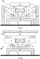
- FIG 1A schematically illustrates a first embodiment of an alignment system 100 not being part of the invention for keeping a first object 1 at a controlled distanced D1 with respect to a second object 2.
- the system 100 comprises an object stage 11 configured to hold a surface 1a of the first object 1 at a distance D1 over a surface 2a of the second object 2.
- An object stage actuator 21 is configured to actuate the object stage 11 to vary the distance D1 between the surfaces 1a,2a of the first and second objects 1,2.
- a sensor device 31 comprising a probe tip 31a is connected at a predetermined probe level distance Dp relative to the surface 1a of the first object 1, in use, held by the object stage 11.
- the probe tip 31a is configured to perform an atomic force measurement AFM of a force F1 exerted via the probe tip 31a on a surface 2a of the second object 2.
- a controller 80 configured to control the object stage actuator 21 as a function of the measured force F1 to keep the first object 1 at the controlled distanced D1 with respect to a second object 2.
- the controller 80 is configured to control the object stage actuator 21 as a function of the probe level distance Dp and the measured force F1.
- the controller 80 is configured to receive a feedback signal S1 from the sensor device 31 and to control the object stage actuator 21 to keep the first object 1 at the controlled distance D1 from the second object 2 based on the feedback signal S1.
- the figure illustrates a method of aligning a first object 1 at a controlled distanced D1 with respect to a second object 2.
- the method comprises providing an object stage 11 to hold a surface 1a of the first object 1 at a distance D1 over a surface 2a of the second object 2.
- the method comprises providing an object stage actuator 21 to actuate the object stage 11 to vary the distance D1 between the surfaces 1a,2a of the first and second objects 1,2.
- the method comprises providing an sensor device 31 comprising a probe tip 31a connected at a predetermined probe level distance Dp relative to the surface 1a of the first object 1.
- the method comprises using the probe tip 31a is to perform an atomic force measurement AFM of a force F1 exerted via the probe tip 31a on a surface 2a of the second object 2.
- the method comprises controlling the object stage actuator 21 as a function of the probe level distance Dp and the measured force F1 to keep the first object 1 at the controlled distanced D1 with respect to a second object 2.
- the method comprises determining the probe level distance Dp between the first object 1 held by the object stage 11 and the probe tip 31a.
- the method comprises moving the second object 2 laterally with respect to the first object 1 while keeping the controlled distance D1 constant.
- the system 100 comprises an object stage configured to hold a surface 2a of the second object 2 at a distance D1 below a surface 1a of the first object 1.
- an object stage actuator 21 is configured to actuate the object stage to vary the distance D1 between the surfaces 1a,2a of the first and second objects 1,2 (however by moving the second object).
- a sensor device 31 comprising a probe tip 31a is connected at a predetermined probe level distance Dp relative to the surface 1a of the first object 1.
- the first object 1 can be held stationary, e.g.
- the probe tip 31a may be configured to perform an atomic force measurement AFM of a force F1 exerted via the probe tip 31a on a surface 2a of the second object 2.
- AFM atomic force measurement
- the probe tip is configured to measure a force exerted on a surface 1a of the first object 1 a system may be obtained that is inverted compared to the embodiment shown in the figure.
- FIG 1B schematically illustrates a second embodiment of an alignments system 100 being part of the invention with adjustable probe level distance Dp.
- the sensor device 31 comprising the probe tip 31a is carried to the object stage 11 via a sensor stage 51, wherein the sensor stage 51 comprises an actuator configured to translate the sensor device in order to variably set the probe level distance Dp between a level of the probe tip 31a and a level of the surface la of the first object 1.
- the probe level distance Dp is measured transverse to the surface 2a of the second object 2.
- the probe level distance Dp is set as a function of a desired distance D1 between the first object 1 and second object 2.
- the probe level distance Dp between the first object 1 and the probe tip 31a is set close or equal to the desired distance D1 between the first object 1 and second object 2, e.g. within a margin of less than one micrometre, less than hundred nanometres, or less than ten nanometres. This may depend e.g. on a proximity at which the probe tip 31a is intended to operate relative to the surface 2a of the second object 2.
- the controller is configured to calibrate the probe level distance Dp between the probe tip 31a and the first object 1.
- the sensor stage 51 is configured to translate the sensor device 31 in the same direction as the object stage actuator 21.
- the sensor stage 51 is configured to translate the sensor device 31 with respect to the first object 1.
- the sensor stage 51 is (only) connected to a fixed surroundings, e.g. fixed structural element 91, via the object stage actuator 21.
- the sensor stage 51 is carried by and moves relative to the object stage 11. This allows more accurately setting a variable distance between the first object 1 and the second object 2 compared to a configuration with two independent stages, e.g. because then an unknown variance of the object stage may affect a determination of the relative distance between the sensor device 31 and the first object 1.
- the fixed structural element 91 may e.g. be directly or indirectly connected to a building structure, e.g. floor 99 and/or substrate table 95. Alternatively, or in addition, the fixed structural element may connected to a metro-frame or main frame of the system.
- FIG 2A schematically illustrates a third embodiment of an alignments system 100 not being part of the invention with multiple sensor devices.
- the system 100 comprises at least two sensor devices 31,32 each configured to measure a force F1,F2 between a respective probe tip 31a,32a and different parts 2a,2b of the surface 2a of the second object 2.
- the system comprises one or more object stage actuators 21,22 configured to control respective distances D1,D2 between the first object 1 and the different parts 2a,2b of the surface of the second object 2.
- the one or more object stage actuators 21,22 are configured to control a distance and tilt of the first object 1 with respect to the surface 2a,2b of the second object 2.
- FIG 2B schematically illustrates a fourth embodiment of an alignments system 100 not being part of the invention comprising an approach stage 60 configured to position the first object 1 with respect to the second object 2.
- a plurality of object stage actuators 21,22 are disposed between the object stage 11 and the approach stage 60.
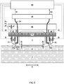
- FIG 3 schematically illustrates a fifth embodiment of an alignments system being part of the invention combining features of some of the other embodiments.
- the alignment system 100 comprises multiple sensor devices with probe tips 31a,32a.
- the alignment system 100 comprises multiple object stage actuators 21,22 disposed between the object stage 11 and an approach stage 60.
- the object stage 11 is configured to hold the first object 1 adjacent the probe tip 31a over the surface 2a of the second object 2.
- the distance D1 between the first object 1 and the second object 2 is less than hundred nanometres, less than fifty nanometres, e.g. between five and twenty nanometres.
- a lateral distance Xa between the probe tip 31a and an edge of the first object 1 along a surface 2a of the second object 2 is less than five centimetres, two centimetres, one centimetre.
- the approach stage 60 comprises an overall slow alignment and approach stage having a resolution e.g. of 100 nm (distance Z5) and/or 10 prad (tilt R1,R2).
- the object stage actuators 21,22 provide the object stage 11 with relatively fast tracking, e.g., having a range of 3 pm and high resolution of less than 1 nanometre.
- the sensor stage 51 comprises a coarse alignment which can be for example manually operated.
- the coarse alignment has a range of 500 pm and resolution of one micrometer.
- the sensor stage 51 comprises medium alignment with a lower range, e.g. 5 ⁇ m and a higher resolution, e.g. 1 nm.
- the probe tip 31a on a 100 kHz cantilever is actuated by a piezo e.g. with 100 kHz dither.
- three or more probe tips can be used as will be described with reference to FIG 4 .
- the system comprises an optical fibre 34 configured to direct light between a cantilever of the sensor device 31 and an interrogator 35.
- the interrogator 35 is an interferometric interrogator.
- the interrogator 35 is configured to send a feedback signal S1 to the controller 80 indicative of a proximity between the probe tip and the surface 2a of the second object 2.
- the controller 80 can e.g. comprise a feedback controller.
- FIGs 4A and 4B schematically illustrate the positioning of three sensor probes.
- a distance D12 (and/or D23,D31) between a first probe tip 31a and a second probe tip 32a is at least two millimetre, at least five millimetre, e.g. between one and five centimetre.
- the alignments systems as described herein comprise at least three probe tips 31a, 32a, 33a.
- each probe tip 31a, 32a, 33a is disposed on a respective cantilever 31b,32b,33b and configured to measure a respective atomic force F1,F2,F3 at different parts 2a,2b,2c of the surface of the second object 2.
- the probe tips 31a, 32a, 33a are arranged in a triangular configuration, e.g. to measure tilt. In another or further embodiment, the probe tips 31a, 32a, 33a are arranged around a circumference of the first object 1 as seen transverse to the surface 2a of the second object 2 in FIG 4B .
- the controller (not shown here) is configured to control a tilt of the first object with respect to the surface 2a of the second object 2 based on the measurements of the three probe tips.
- the controller is configured to control a tilt of the first object with respect to the surface 2a of the second object 2 based on the measurements of the three probe tips.
- three non-coupled controllers can be used.
- three or more AFMs are synchronized to cooperate to keep a specific alignment..
- FIG 5A schematically illustrates example details of a probe tip 31a adjacent the first object 1 over a surface 2a of the second object 2.
- the probe tip 31a comprises an AFM tip. In another or further embodiment, the probe tip 31a is disposed on a cantilever 31b. In another or further embodiment, the sensor device 31 comprises a high frequency actuator 31c, e.g. piezo, configured vibrate the probe tip in a dynamic mode, e.g. tapping mode.
- a high frequency actuator 31c e.g. piezo
- the sensor device 31 comprises a light source 31d configured to reflect a light beam L1 off the cantilever 31b.
- the sensor device 31 comprises a sensor, e.g. position sensitive sensor 31e configured to measure a direction of the reflected light beam L1 to determine a proximity between the probe tip 31a and the surface 2a of the second object 2, e.g. based on the atomic force F1 influencing the frequency, phase, angle or other observable of the cantilever.
- FIG 5B schematically illustrates use of the alignment system 100 in a lithographic apparatus 200.
- a lithographic apparatus 200 comprises the alignment system 100 as described herein.
- the first object 1 is a lens and the object stage 11 is configured to hold the lens
- the second object 2 is a wafer.
- the lithographic apparatus 200 comprises an actinic light source 5. In another or further embodiment, the lithographic apparatus 200 comprises a mask stage 4. In another or further embodiment, the lens is part of an imaging system configured to project an image (e.g. of the mask) onto the wafer.
- the lithographic apparatus 200 comprises a wafer stage 3.
- the system is configured to calibrate the probe level distance between the probe tip 31a and the lens 1 based on an image projected through the lens onto the second object 2, e.g. by a contrast measurement of the projected image.
- the wafer stage 3 is configured to move the wafer 2 along a surface direction X i.e. transverse to the distance D1 between the lens and the wafer.
- the system is configured to keep the first object 1 at the controlled distance D1 from the second object 2 while moving the first object 1 over the surface 2a of the second object 2.
- the system is configured to keep the lens 1 at a controlled distance from the wafer 2 while moving the lens over the surface of the wafer.
- a distance between the lens and wafer is kept at a value in a range of 1-100 nm.
- the lithographic apparatus 200 may operate in a scanning mode.
- a conventional AFM system typically does not have a reference point, i.e. wherein an absolute height with respect to the reference is implemented, contrary to the present system wherein level sensing is used.
- the AFM stage can be combined with the stage of the object to be positioned.
- FIGs 6A-6C schematically show an embodiment for setting a distance between a first object 1 and a second object 2.
- a distance D1 between the first object 1 and the second object 2 is lowered by a sequence of steps. For example in one step, as shown by comparison of FIGs 6A and 6B , a distance Ds between the sensor device 31 and the second object 2 is lowered until the sensor device 31 measures a predetermined force F1 exerted via the probe tip on the surface of the second object 2. For example in another or further step, as shown by comparison of FIGs 6B and 6C , the distance between the sensor device 31 and the second object 2 is kept constant (e.g. based a feedback of the measured force F1) while a distance between a level of the first object 1 and a level of the sensor device 31 is lowered until the predetermined probe level distance Dp is reached.
- Such sequence of steps may provide an advantage in that the sensor stage 51 can be relatively light and therefore more easily move to quickly approach the second object to determine its position.
- the heavier object stage 11 (holding the first object 1) may then follow at a controlled descent with relatively high speed while decelerating before the determined position without the risk of overshoot and running into the second object.
- the distance Ds between the sensor device 31 and the second object 2 is decreased by actuating the sensor stage 51.
- the distance between the sensor device 31 and the second object 2 is kept constant while the distance between the first object 1 and the sensor device 31 is lowered by simultaneously actuating the sensor stage 51 and the object stage 11 in opposite directions.
- a first feedback loop includes actuating the sensor stage 51 based on the measured force F1 exerted via the probe tip on the surface 2a of the second object 2.
- a second feedback loop includes actuating the object stage 11 based on a direct distance measurement between the sensor device 31 and the first object 1 and/or object stage 11.
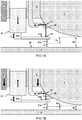
- FIGs 7A and 7B schematically show an embodiment for directly measuring a distance between a level of the first object 1 and a level of the sensor device 31.
- FIG 7A shows the object stage 11 in a retracted position while the sensor stage 51 is set to an approached position to sense the second object 2, e.g. substrate, via an AFM measurement of the force F1 on the probe tip 31a.
- FIG 7B shows the object stage 11 in an approached position which can be achieved by simultaneously using the object stage actuator 21 to lower the object stage 11 while actuating the sensor stage 51 to retract with respect to the object stage 11 to keep a fixed distance with respect to the surface of the second object 2.
- the system comprises a distance sensing arrangement configured to directly measure a distance between a first position P1 that is fixed relative to the first object 1 and/or the object stage 11 (both of which are fixed relative to each other), and a second position P2 that is fixed relative to the sensor device 31 and/or sensor stage 51.
- the first position P1 is a position that moves in a fixed relation with respect to the first object 1 and/or object stage 11.
- the second position P2 is a position that moves in a fixed relation with respect to the sensor device 31.
- a controller (not shown) is configured to calculated a change of the probe level distance Dp based on a change of the measured distance between the first and second positions P1,P2.
- the controller is configured to determine a position of the sensor device 31 with respect to the first object 1 based on an interferometric measurement.
- the probe level distance Dp may be monitored based on feedback of the distance measurement between the first and second positions P1,P2.
- the probe level distance can also be used in a closed feedback loop to achieve or maintain a predetermined distance.
- the system comprises a light guide configured to direct a light beam L2 from a light source along a light path to a light sensor, wherein the light path traverses the first and second positions P1,P2.
- the first position P1 is disposed on a surface of the first object 1, e.g. lens surface.
- the second position P2 is preferably disposed on a surface of the sensor device 31, e.g. the cantilever 31b or any other position that moves with the sensor stage 51.
- the light beam L2 is reflected at both the first position P1 and the second position P2. For example, the light beam L2 is reflected off a surface of the first object 1, e.g. lens surface.
- a prism 1P or other light guiding means attached to a surface of the first object 1 to guide and/or reflect the light beam L2.
- the light beam L2 is reflected off a surface of the sensor device 31, e.g. the light beam is reflected off the cantilever 31b.
- the light guide comprises an optical fibre 34.
- the light guide is configured to send the light beam L2 to reflect onto the surfaces of the first object 1 and sensor device 31 and to receive a back reflection thereof.
- the system is configured to perform an interferometric measurement of the light beam L2 to measure a change of the distance between the first and second positions P1,P2.
- an optical fiber 34 and interrogator 35 such as shown with reference to FIG 3B can be used.
- the system can also use an integrated sensor and actuator, e.g. electrostatic, piezoresistive, thermal, et cetera, for measuring one or more of the positions P1, P2 and/or a distance there between.
- an integrated sensor and actuator e.g. electrostatic, piezoresistive, thermal, et cetera, for measuring one or more of the positions P1, P2 and/or a distance there between.
- FIGs 8A and 8B schematically show another embodiment for directly measuring a distance between a level of the first object 1 and a level of the sensor device 31.
- the distance sensing arrangement comprises a light source 31d and a light sensor 31e.
- the light source 31d and/or light sensor 31e are fixed to the object stage 11.
- the light source 31d is configured to reflect a light beam L1 via a surface of the sensor device 31, e.g. cantilever 31b.
- the light sensor 31e is a position sensitive detector configured to measure a position where a reflection of the light beam impinges the light sensor 31e. It will be appreciated by comparing FIGs 8A and 8B that an average B of the position may be used as a measure for the distance between the levels of the sensor device 31 and the first object 1.
- an amplitude " ⁇ ", period, and/or phase of the position can be used a measure for the force F1 between the sensor device 31 and the second object 2.
- a low pass filter is used on an output signal of the light sensor 31e for providing a signal that is indicative of the relative position of the sensor device 31 with respect to the object stage 11.
- a high pass filter can be used to determine the variation of the cantilever angles which is indicative of the force F1 and/or proximity of the surface 2a.
- the second object 2 can be moved by an object stage, e.g. moveable substrate table (not shown).
- object stage e.g. moveable substrate table (not shown).
- the cantilever is sent down to detect the surface (or the substrate is brought up to detect) and then slowly and in a controlled way the substrate or sample is brought up to a defined position, e.g. between P1 and P2 as illustrated in FIG 7 .
- a defined position e.g. between P1 and P2 as illustrated in FIG 7 .
- an AFM sensor device with probe tip on a cantilever is used as a force sensor for determining distance.
- probe tips e.g. having higher tip radius may be used with similar effect.
- an optical beam deflection (OBD) setup and/or interferometric measurement using optical fibres is used as a readout technique to measure the deflection of the sensing cantilever
- OBD optical beam deflection
- other readout techniques for measuring the sensing cantilever motion may be envisaged by those skilled in the art having the benefit of the present disclosure for achieving a similar function and result.
- the systems and methods as described herein can also be applied in a parallel setting, e.g. multiple systems can be simultaneously active. For example two or more systems can be simultaneously used to keep respective objects at respective distances.
- a first system may keep a first lens at a predetermined distance from a wafer while a second system keeps a second lens at another or the same predetermined distance from the same wafer, e.g. at a different position on the wafer.
- Using multiple systems in parallel may further increase productivity.
- the systems in a parallel setting may also cooperate to achieve even further advantage.
- Components may optionally be combined or split up into one or more alternative components.
- the various elements of the embodiments as discussed and shown offer certain advantages, such as prevention of sample or tip damage, higher precision of the measurement, and enabling extraction of quantitative physical and mechanical properties.
- any one of the above embodiments or processes may be combined with one or more other embodiments or processes to provide even further improvements in finding and matching designs and advantages.
- this disclosure offers particular advantages e.g. in nanosystems for industrial applications, wherein accurate alignment between components is desired, e.g. semiconductor, metrology, and/or bio-medical fields, and in general can be applied for any alignment system.
Landscapes
- Physics & Mathematics (AREA)
- General Physics & Mathematics (AREA)
- Health & Medical Sciences (AREA)
- General Health & Medical Sciences (AREA)
- Nuclear Medicine, Radiotherapy & Molecular Imaging (AREA)
- Radiology & Medical Imaging (AREA)
- Exposure And Positioning Against Photoresist Photosensitive Materials (AREA)
- Length Measuring Devices With Unspecified Measuring Means (AREA)
Claims (15)
- Ausrichtungssystem (100) zum Positionieren und/oder Halten eines ersten Objekts (1) in einem kontrollierten Abstand (D1) in Bezug auf ein zweites Objekt (2), wobei das System (100) umfasst- einen Objekttisch (11), der zum Halten des ersten Objekts (1) oder des zweiten Objekts (2) ausgelegt ist, wobei eine Oberfläche (1a) des ersten Objekts (1) in einem Abstand (D1) über einer Oberfläche (2a) des zweiten Objekts (2) liegt;- einen Objekttischaktuator (21), der dazu ausgelegt ist, den Objekttisch (11) zu betätigen, um den Abstand (D1) zwischen den Oberflächen (1a, 2a) der ersten und zweiten Objekte (1, 2) zu verändern;- eine Sensorvorrichtung (31), die eine Sondenspitze (31a) umfasst, die in einem vorbestimmten Sondenpegelabstand (Dp) relativ zu der Oberfläche (1a) des ersten Objekts (1) verbunden ist, wobei die Sondenspitze (31a) dazu ausgelegt ist, eine Atomkraftmessung (AFM) einer Kraft (F1) durchzuführen, die über die Sondenspitze (31a) auf eine Oberfläche (2a) des zweiten Objekts (2) ausgeübt wird;- eine Steuerung (80), die dazu ausgelegt ist, den Objekttischaktuator (21) als eine Funktion des Sondenpegelabstands (Dp) und der gemessenen Kraft (F1) zu steuern, um das erste Objekt (1) in dem kontrollierten Abstand (D1) in Bezug auf ein zweites Objekt (2) zu positionieren und/oder zu halten.dadurch gekennzeichnet, dass die Sensorvorrichtung (31), die die Sondenspitze (31a) umfasst, von dem Objekttisch (11) über einen Sensortisch (51) getragen wird, wobei der Sensortisch (51) einen Aktuator umfasst, der so ausgelegt ist, dass er die Sensorvorrichtung (31) verschiebt, um den Sondenpegelabstand (Dp) zwischen einem Pegel der Sondenspitze (31a) und einem Pegel der Oberfläche (1a) des ersten Objekts (1) variabel einzustellen.
- System nach Anspruch 1, wobei der Sensortisch (51) nur über den Objekttischaktuator (21) mit einem festen Strukturelement (91) verbunden ist.
- System nach Anspruch 1, wobei die Steuerung so ausgelegt ist, dass sie den Sondenpegelabstand (Dp) zwischen der Sondenspitze (31a) und dem ersten Objekt (1) kalibriert.
- System nach einem der vorhergehenden Ansprüche, wobei die Steuerung so ausgelegt ist, dass sie einen Abstand (D1) zwischen dem ersten Objekt (1) und dem zweiten Objekt (2) durch folgende Sequenz verringert- Verringern eines Abstands (Ds) zwischen der Sensorvorrichtung (31) und dem zweiten Objekt (2), bis die Sensorvorrichtung (31) eine vorbestimmte Kraft (F1) misst, die über die Sondenspitze (31a) auf die Oberfläche (2a) des zweiten Objekts (2) ausgeübt wird; und- den Abstand zwischen der Sensorvorrichtung (31) und dem zweiten Objekt (2) basierend auf einer Rückmeldung der gemessenen Kraft (F1) konstant zu halten, während ein Abstand zwischen einem Pegel des ersten Objekts (1) und einem Pegel der Sensorvorrichtung (31) verringert wird, bis der vorbestimmte Sondenpegelabstand (Dp) erreicht ist.
- System nach einem der vorhergehenden Ansprüche, wobei das System eine Abstandserfassungsanordnung umfasst, die so ausgelegt ist, dass sie einen Abstand zwischen einer ersten Position (P1), die relativ zu dem ersten Objekt (1) und/oder Objekttisch (11) fixiert ist, und einer zweiten Position (P2), die relativ zu der Sensorvorrichtung (31) und/oder dem Sensortisch (51) fixiert ist, direkt misst, wobei das System einen Lichtleiter umfasst, der so ausgelegt ist, dass er einen Lichtstrahl (L2) von einer Lichtquelle entlang eines Lichtpfads zu einem Lichtsensor leitet, wobei der Lichtpfad die erste und die zweite Position (P1,P2) durchquert, wobei das System dazu ausgelegt ist, eine interferometrische Messung des Lichtstrahls (L2) durchzuführen, um eine Änderung des Abstands zwischen der ersten und der zweiten Position (P1,P2) zu messen.
- System nach einem der vorhergehenden Ansprüche, das mindestens zwei Sensorvorrichtungen (31,32) umfasst, die jeweils so ausgelegt sind, dass sie eine Kraft (F1,F2) zwischen einer jeweiligen Sondenspitze (31a,32a) und verschiedenen Teilen (2a,2b) der Oberfläche (2a) des zweiten Objekts (2) messen.
- System nach einem der vorhergehenden Ansprüche, das einen Annäherungstisch (60) umfasst, der so ausgelegt ist, dass er das erste Objekt (1) in Bezug auf das zweite Objekt (2) positioniert, wobei mehrere Annäherungstischaktuatoren (21,22) zwischen dem Objekttisch (11) und dem Annäherungstisch (60) angeordnet sind, um entsprechende Abstände (D1, D2) zwischen dem ersten Objekt (1) und den verschiedenen Teilen (2a,2b) der Oberfläche des zweiten Objekts (2) zu steuern.
- System nach einem der vorhergehenden Ansprüche, das wenigstens drei Sondenspitzen (31a, 32a, 33a) umfasst, die in einer dreieckigen Konfiguration angeordnet sind.
- System nach Anspruch 8, wobei die Steuerung (80) so ausgelegt ist, dass sie eine Neigung (R1,R2) des ersten Objekts (1) in Bezug auf die Oberfläche (2a) des zweiten Objekts (2) basierend auf den Messungen der drei Sondenspitzen steuert.
- System nach einem der vorhergehenden Ansprüche, wobei das System dazu ausgelegt ist, das erste Objekt (1) in dem kontrollierten Abstand (D1) von dem zweiten Objekt (2) zu halten, während es das erste Objekt (1) über die Oberfläche (2a) des zweiten Objekts (2) bewegt.
- Lithographisches Gerät (200) mit dem Ausrichtungssystem (100) nach einem der vorhergehenden Ansprüche.
- Verfahren zum Ausrichten eines ersten Objekts (1) in einem kontrollierten Abstand (D1) in Bezug auf ein zweites Objekt (2), wobei das Verfahren umfasst- Bereitstellen eines Objekttischs (11) zum Halten des ersten Objekts (1) oder des zweiten Objekts (2), wobei sich eine Oberfläche (1a) des ersten Objekts (1) in einem Abstand (D1) zu einer Oberfläche (2a) des zweiten Objekts (2) befindet;- Bereitstellen eines Objekttischaktuators (21) zur Betätigung des Objekttischs (11), um den Abstand (D1) zwischen den Oberflächen (1a,2a) der ersten und zweiten Objekte (1, 2) zu verändern;- Bereitstellen einer Sensorvorrichtung (31) mit einer Sondenspitze (31a), die in einem vorbestimmten Sondenpegelabstand (Dp) relativ zur Oberfläche (1a) des ersten Objekts (1) verbunden ist;- unter Verwendung der Sondenspitze (31a) zur Durchführung einer Atomkraftmessung (AFM) einer Kraft (F1), die über die Sondenspitze (31a) auf eine Oberfläche (2a) des zweiten Objekts (2) ausgeübt wird;- Steuerung des Objekttischaktuators (21) in Abhängigkeit vom Sondenpegelabstand (Dp) und der gemessenen Kraft (F1), um das erste Objekt (1) in Bezug auf ein zweites Objekt (2) in dem kontrollierten Abstand (D1) zu halten- dadurch gekennzeichnet, dass die Sensorvorrichtung (31), die die Sondenspitze (31a) umfasst, von dem Objekttisch (11) über einen Sensortisch (51) getragen wird, wobei der Sensortisch (51) einen Aktuator umfasst, der so ausgelegt ist, dass er die Sensorvorrichtung (31) verschiebt, um den Sondenpegelabstand (Dp) zwischen einem Pegel der Sondenspitze (31a) und einem Pegel der Oberfläche (1a) des ersten Objekts (1) variabel einzustellen.
- Verfahren nach Anspruch 12, wobei das zweite Objekt (2) ein Substrat ist und das erste Objekt (1) eine Linse zum Projizieren von Bildern auf das Substrat ist, wobei die Bilder durch eine wiederholte Sequenz projiziert werden, die einschließt- Bewegen der Linse relativ zu einer Oberfläche des Substrats in eine zurückgezogene Position;- Verringern eines Abstands zwischen der Linse und dem Substrat, bis eine Abbildungsposition erreicht ist, wobei die Abbildungsposition basierend auf der Atomkraftmessung der Sensorvorrichtung (31) bestimmt wird;- Projizieren eines Bildes durch das Objektiv auf das Substrat; und- Zurückziehen der Linse und/oder des Substrats, um den Abstand dazwischen zu vergrößern und sich in eine nächste Position zu bewegen.
- Verfahren nach Anspruch 13, wobei die Linse und/oder das Substrat aus der eingefahrenen Position durch folgende Sequenz in die Abbildungsposition gebracht wird- Verringern eines Abstands (Ds) zwischen der Sensorvorrichtung (31) und dem Substrat, bis die Sensorvorrichtung (31) eine vorbestimmte Kraft (F1) misst, die über die Sondenspitze (31a) auf die Oberfläche (2a) des Substrats ausgeübt wird; und- Konstanthalten des Abstands zwischen der Sensorvorrichtung (31) und dem Substrat basierend auf einer Rückmeldung der gemessenen Kraft (F1), während ein Abstand zwischen einem Pegel der Linse und einem Pegel der Sensorvorrichtung (31) verringert wird, bis ein vorbestimmter Sondenpegelabstand (Dp), der der Abbildungsposition entspricht, erreicht ist.
- Verfahren nach Anspruch 14, wobei der Abstand zwischen einem Pegel der Linse und einem Pegel der Sensorvorrichtung (31) durch eine interferometrische Messung eines Lichtstrahls gemessen wird, der von einer mit der Linse verbundenen Oberfläche und einer mit der Sensorvorrichtung (31) verbundenen Oberfläche reflektiert wird.
Applications Claiming Priority (2)
| Application Number | Priority Date | Filing Date | Title |
|---|---|---|---|
| EP15194135 | 2015-11-11 | ||
| PCT/NL2016/050780 WO2017082725A1 (en) | 2015-11-11 | 2016-11-10 | Alignment system and method |
Publications (2)
| Publication Number | Publication Date |
|---|---|
| EP3374828A1 EP3374828A1 (de) | 2018-09-19 |
| EP3374828B1 true EP3374828B1 (de) | 2021-10-06 |
Family
ID=54539983
Family Applications (1)
| Application Number | Title | Priority Date | Filing Date |
|---|---|---|---|
| EP16809198.1A Active EP3374828B1 (de) | 2015-11-11 | 2016-11-10 | Ausrichtungssystem und verfahren |
Country Status (3)
| Country | Link |
|---|---|
| US (1) | US10663874B2 (de) |
| EP (1) | EP3374828B1 (de) |
| WO (1) | WO2017082725A1 (de) |
Families Citing this family (2)
| Publication number | Priority date | Publication date | Assignee | Title |
|---|---|---|---|---|
| CN112445088B (zh) * | 2020-12-04 | 2025-10-10 | 百及纳米科技(上海)有限公司 | 一种步进式光刻机、其工作方法及图形对准装置 |
| AT524841B1 (de) * | 2021-06-07 | 2022-10-15 | Univ Wien Tech | Verfahren und Vorrichtung zur Störgrößenkompensation bei der Positionierung eines Probenträgers |
Family Cites Families (6)
| Publication number | Priority date | Publication date | Assignee | Title |
|---|---|---|---|---|
| JP3074579B2 (ja) | 1992-01-31 | 2000-08-07 | キヤノン株式会社 | 位置ずれ補正方法 |
| JP3081979B2 (ja) * | 1992-05-08 | 2000-08-28 | セイコーインスツルメンツ株式会社 | 顕微鏡 |
| JPH0845814A (ja) * | 1994-07-27 | 1996-02-16 | Nikon Corp | 露光装置および位置決め方法 |
| US5907405A (en) * | 1995-09-01 | 1999-05-25 | Nikon Corporation | Alignment method and exposure system |
| US7021120B2 (en) | 2004-04-28 | 2006-04-04 | Asml Holding N.V. | High resolution gas gauge proximity sensor |
| WO2014188379A1 (en) | 2013-05-23 | 2014-11-27 | Applied Materials Israel, Ltd. | An evaluation system and a method for evaluating a substrate |
-
2016
- 2016-11-10 US US15/775,171 patent/US10663874B2/en active Active
- 2016-11-10 EP EP16809198.1A patent/EP3374828B1/de active Active
- 2016-11-10 WO PCT/NL2016/050780 patent/WO2017082725A1/en not_active Ceased
Also Published As
| Publication number | Publication date |
|---|---|
| US20190250524A1 (en) | 2019-08-15 |
| EP3374828A1 (de) | 2018-09-19 |
| WO2017082725A1 (en) | 2017-05-18 |
| US10663874B2 (en) | 2020-05-26 |
Similar Documents
| Publication | Publication Date | Title |
|---|---|---|
| US7562564B2 (en) | Scanning probe microscope and sample observing method using this and semiconductor device production method | |
| US8220066B2 (en) | Vibration compensation in probe microscopy | |
| US5852232A (en) | Acoustic sensor as proximity detector | |
| JP5580296B2 (ja) | プローブ検出システム | |
| US8656509B2 (en) | Scanning probe microscope and surface shape measuring method using same | |
| CN102209609B (zh) | 晶圆级纳米计量系统、用于感测加工元件位置的方法 | |
| US7966867B2 (en) | Scanning probe microscope | |
| KR100751928B1 (ko) | 주사형 프로브 현미경과 그 탐침 이동 제어방법 | |
| JP2001116869A (ja) | サンプル検査及び/又は処理装置 | |
| EP3374828B1 (de) | Ausrichtungssystem und verfahren | |
| JP4790551B2 (ja) | 微細形状測定装置 | |
| KR102442240B1 (ko) | 거리 센서, 배치 시스템 및 방법 | |
| US6057914A (en) | Method for detecting and identifying a lens aberration by measurement of sidewall angles by atomic force microscopy | |
| US8028343B2 (en) | Scanning probe microscope with independent force control and displacement measurements | |
| KR102700231B1 (ko) | 지지 표면 상에 스캔 헤드를 포지셔닝하기 위한 포지셔닝 암 및 방법 | |
| JPH02128109A (ja) | 表面形状測定装置 | |
| JP2018526812A (ja) | 変形体の変位測定 | |
| KR100298301B1 (ko) | 굴곡센서를 내장한 스캐닝 프로브 및 이를 이용한 굴곡측정장치 | |
| Sturwald et al. | Large scale atomic force microscopy for characterisation of optical surfaces and coatings | |
| Sokolov et al. | and Hans U. Danzebrink | |
| JP2006276027A (ja) | 走査プローブ顕微鏡 | |
| JP2006337379A (ja) | 走査プローブ顕微鏡 | |
| JPH0626852A (ja) | 走査型プローブ顕微鏡 | |
| JP2004069656A (ja) | 走査型プローブ顕微鏡の測定方法 |
Legal Events
| Date | Code | Title | Description |
|---|---|---|---|
| STAA | Information on the status of an ep patent application or granted ep patent |
Free format text: STATUS: UNKNOWN |
|
| STAA | Information on the status of an ep patent application or granted ep patent |
Free format text: STATUS: THE INTERNATIONAL PUBLICATION HAS BEEN MADE |
|
| PUAI | Public reference made under article 153(3) epc to a published international application that has entered the european phase |
Free format text: ORIGINAL CODE: 0009012 |
|
| STAA | Information on the status of an ep patent application or granted ep patent |
Free format text: STATUS: REQUEST FOR EXAMINATION WAS MADE |
|
| 17P | Request for examination filed |
Effective date: 20180531 |
|
| AK | Designated contracting states |
Kind code of ref document: A1 Designated state(s): AL AT BE BG CH CY CZ DE DK EE ES FI FR GB GR HR HU IE IS IT LI LT LU LV MC MK MT NL NO PL PT RO RS SE SI SK SM TR |
|
| AX | Request for extension of the european patent |
Extension state: BA ME |
|
| DAV | Request for validation of the european patent (deleted) | ||
| DAX | Request for extension of the european patent (deleted) | ||
| GRAP | Despatch of communication of intention to grant a patent |
Free format text: ORIGINAL CODE: EPIDOSNIGR1 |
|
| STAA | Information on the status of an ep patent application or granted ep patent |
Free format text: STATUS: GRANT OF PATENT IS INTENDED |
|
| RIC1 | Information provided on ipc code assigned before grant |
Ipc: G03F 7/20 20060101AFI20210408BHEP Ipc: G03F 9/00 20060101ALI20210408BHEP Ipc: G01Q 10/06 20100101ALI20210408BHEP Ipc: G01Q 30/02 20100101ALI20210408BHEP Ipc: G01Q 70/06 20100101ALI20210408BHEP Ipc: G01Q 20/02 20100101ALI20210408BHEP Ipc: G01Q 60/24 20100101ALI20210408BHEP |
|
| INTG | Intention to grant announced |
Effective date: 20210428 |
|
| GRAS | Grant fee paid |
Free format text: ORIGINAL CODE: EPIDOSNIGR3 |
|
| GRAA | (expected) grant |
Free format text: ORIGINAL CODE: 0009210 |
|
| STAA | Information on the status of an ep patent application or granted ep patent |
Free format text: STATUS: THE PATENT HAS BEEN GRANTED |
|
| AK | Designated contracting states |
Kind code of ref document: B1 Designated state(s): AL AT BE BG CH CY CZ DE DK EE ES FI FR GB GR HR HU IE IS IT LI LT LU LV MC MK MT NL NO PL PT RO RS SE SI SK SM TR |
|
| REG | Reference to a national code |
Ref country code: GB Ref legal event code: FG4D |
|
| REG | Reference to a national code |
Ref country code: CH Ref legal event code: EP Ref country code: AT Ref legal event code: REF Ref document number: 1436737 Country of ref document: AT Kind code of ref document: T Effective date: 20211015 |
|
| REG | Reference to a national code |
Ref country code: IE Ref legal event code: FG4D |
|
| REG | Reference to a national code |
Ref country code: DE Ref legal event code: R096 Ref document number: 602016064686 Country of ref document: DE |
|
| REG | Reference to a national code |
Ref country code: LT Ref legal event code: MG9D |
|
| REG | Reference to a national code |
Ref country code: NL Ref legal event code: FP |
|
| REG | Reference to a national code |
Ref country code: AT Ref legal event code: MK05 Ref document number: 1436737 Country of ref document: AT Kind code of ref document: T Effective date: 20211006 |
|
| PG25 | Lapsed in a contracting state [announced via postgrant information from national office to epo] |
Ref country code: RS Free format text: LAPSE BECAUSE OF FAILURE TO SUBMIT A TRANSLATION OF THE DESCRIPTION OR TO PAY THE FEE WITHIN THE PRESCRIBED TIME-LIMIT Effective date: 20211006 Ref country code: LT Free format text: LAPSE BECAUSE OF FAILURE TO SUBMIT A TRANSLATION OF THE DESCRIPTION OR TO PAY THE FEE WITHIN THE PRESCRIBED TIME-LIMIT Effective date: 20211006 Ref country code: FI Free format text: LAPSE BECAUSE OF FAILURE TO SUBMIT A TRANSLATION OF THE DESCRIPTION OR TO PAY THE FEE WITHIN THE PRESCRIBED TIME-LIMIT Effective date: 20211006 Ref country code: BG Free format text: LAPSE BECAUSE OF FAILURE TO SUBMIT A TRANSLATION OF THE DESCRIPTION OR TO PAY THE FEE WITHIN THE PRESCRIBED TIME-LIMIT Effective date: 20220106 Ref country code: AT Free format text: LAPSE BECAUSE OF FAILURE TO SUBMIT A TRANSLATION OF THE DESCRIPTION OR TO PAY THE FEE WITHIN THE PRESCRIBED TIME-LIMIT Effective date: 20211006 |
|
| PG25 | Lapsed in a contracting state [announced via postgrant information from national office to epo] |
Ref country code: IS Free format text: LAPSE BECAUSE OF FAILURE TO SUBMIT A TRANSLATION OF THE DESCRIPTION OR TO PAY THE FEE WITHIN THE PRESCRIBED TIME-LIMIT Effective date: 20220206 Ref country code: SE Free format text: LAPSE BECAUSE OF FAILURE TO SUBMIT A TRANSLATION OF THE DESCRIPTION OR TO PAY THE FEE WITHIN THE PRESCRIBED TIME-LIMIT Effective date: 20211006 Ref country code: PT Free format text: LAPSE BECAUSE OF FAILURE TO SUBMIT A TRANSLATION OF THE DESCRIPTION OR TO PAY THE FEE WITHIN THE PRESCRIBED TIME-LIMIT Effective date: 20220207 Ref country code: PL Free format text: LAPSE BECAUSE OF FAILURE TO SUBMIT A TRANSLATION OF THE DESCRIPTION OR TO PAY THE FEE WITHIN THE PRESCRIBED TIME-LIMIT Effective date: 20211006 Ref country code: NO Free format text: LAPSE BECAUSE OF FAILURE TO SUBMIT A TRANSLATION OF THE DESCRIPTION OR TO PAY THE FEE WITHIN THE PRESCRIBED TIME-LIMIT Effective date: 20220106 Ref country code: LV Free format text: LAPSE BECAUSE OF FAILURE TO SUBMIT A TRANSLATION OF THE DESCRIPTION OR TO PAY THE FEE WITHIN THE PRESCRIBED TIME-LIMIT Effective date: 20211006 Ref country code: HR Free format text: LAPSE BECAUSE OF FAILURE TO SUBMIT A TRANSLATION OF THE DESCRIPTION OR TO PAY THE FEE WITHIN THE PRESCRIBED TIME-LIMIT Effective date: 20211006 Ref country code: GR Free format text: LAPSE BECAUSE OF FAILURE TO SUBMIT A TRANSLATION OF THE DESCRIPTION OR TO PAY THE FEE WITHIN THE PRESCRIBED TIME-LIMIT Effective date: 20220107 Ref country code: ES Free format text: LAPSE BECAUSE OF FAILURE TO SUBMIT A TRANSLATION OF THE DESCRIPTION OR TO PAY THE FEE WITHIN THE PRESCRIBED TIME-LIMIT Effective date: 20211006 |
|
| REG | Reference to a national code |
Ref country code: CH Ref legal event code: PL |
|
| REG | Reference to a national code |
Ref country code: DE Ref legal event code: R097 Ref document number: 602016064686 Country of ref document: DE |
|
| PG25 | Lapsed in a contracting state [announced via postgrant information from national office to epo] |
Ref country code: SM Free format text: LAPSE BECAUSE OF FAILURE TO SUBMIT A TRANSLATION OF THE DESCRIPTION OR TO PAY THE FEE WITHIN THE PRESCRIBED TIME-LIMIT Effective date: 20211006 Ref country code: SK Free format text: LAPSE BECAUSE OF FAILURE TO SUBMIT A TRANSLATION OF THE DESCRIPTION OR TO PAY THE FEE WITHIN THE PRESCRIBED TIME-LIMIT Effective date: 20211006 Ref country code: RO Free format text: LAPSE BECAUSE OF FAILURE TO SUBMIT A TRANSLATION OF THE DESCRIPTION OR TO PAY THE FEE WITHIN THE PRESCRIBED TIME-LIMIT Effective date: 20211006 Ref country code: MC Free format text: LAPSE BECAUSE OF FAILURE TO SUBMIT A TRANSLATION OF THE DESCRIPTION OR TO PAY THE FEE WITHIN THE PRESCRIBED TIME-LIMIT Effective date: 20211006 Ref country code: LU Free format text: LAPSE BECAUSE OF NON-PAYMENT OF DUE FEES Effective date: 20211110 Ref country code: EE Free format text: LAPSE BECAUSE OF FAILURE TO SUBMIT A TRANSLATION OF THE DESCRIPTION OR TO PAY THE FEE WITHIN THE PRESCRIBED TIME-LIMIT Effective date: 20211006 Ref country code: DK Free format text: LAPSE BECAUSE OF FAILURE TO SUBMIT A TRANSLATION OF THE DESCRIPTION OR TO PAY THE FEE WITHIN THE PRESCRIBED TIME-LIMIT Effective date: 20211006 Ref country code: CZ Free format text: LAPSE BECAUSE OF FAILURE TO SUBMIT A TRANSLATION OF THE DESCRIPTION OR TO PAY THE FEE WITHIN THE PRESCRIBED TIME-LIMIT Effective date: 20211006 Ref country code: BE Free format text: LAPSE BECAUSE OF NON-PAYMENT OF DUE FEES Effective date: 20211130 |
|
| REG | Reference to a national code |
Ref country code: BE Ref legal event code: MM Effective date: 20211130 |
|
| PLBE | No opposition filed within time limit |
Free format text: ORIGINAL CODE: 0009261 |
|
| STAA | Information on the status of an ep patent application or granted ep patent |
Free format text: STATUS: NO OPPOSITION FILED WITHIN TIME LIMIT |
|
| PG25 | Lapsed in a contracting state [announced via postgrant information from national office to epo] |
Ref country code: LI Free format text: LAPSE BECAUSE OF NON-PAYMENT OF DUE FEES Effective date: 20211130 Ref country code: CH Free format text: LAPSE BECAUSE OF NON-PAYMENT OF DUE FEES Effective date: 20211130 |
|
| 26N | No opposition filed |
Effective date: 20220707 |
|
| GBPC | Gb: european patent ceased through non-payment of renewal fee |
Effective date: 20220106 |
|
| PG25 | Lapsed in a contracting state [announced via postgrant information from national office to epo] |
Ref country code: GB Free format text: LAPSE BECAUSE OF NON-PAYMENT OF DUE FEES Effective date: 20220106 Ref country code: AL Free format text: LAPSE BECAUSE OF FAILURE TO SUBMIT A TRANSLATION OF THE DESCRIPTION OR TO PAY THE FEE WITHIN THE PRESCRIBED TIME-LIMIT Effective date: 20211006 |
|
| PG25 | Lapsed in a contracting state [announced via postgrant information from national office to epo] |
Ref country code: SI Free format text: LAPSE BECAUSE OF FAILURE TO SUBMIT A TRANSLATION OF THE DESCRIPTION OR TO PAY THE FEE WITHIN THE PRESCRIBED TIME-LIMIT Effective date: 20211006 |
|
| PG25 | Lapsed in a contracting state [announced via postgrant information from national office to epo] |
Ref country code: IT Free format text: LAPSE BECAUSE OF FAILURE TO SUBMIT A TRANSLATION OF THE DESCRIPTION OR TO PAY THE FEE WITHIN THE PRESCRIBED TIME-LIMIT Effective date: 20211006 Ref country code: HU Free format text: LAPSE BECAUSE OF FAILURE TO SUBMIT A TRANSLATION OF THE DESCRIPTION OR TO PAY THE FEE WITHIN THE PRESCRIBED TIME-LIMIT; INVALID AB INITIO Effective date: 20161110 |
|
| P01 | Opt-out of the competence of the unified patent court (upc) registered |
Effective date: 20230522 |
|
| PG25 | Lapsed in a contracting state [announced via postgrant information from national office to epo] |
Ref country code: CY Free format text: LAPSE BECAUSE OF FAILURE TO SUBMIT A TRANSLATION OF THE DESCRIPTION OR TO PAY THE FEE WITHIN THE PRESCRIBED TIME-LIMIT Effective date: 20211006 |
|
| PG25 | Lapsed in a contracting state [announced via postgrant information from national office to epo] |
Ref country code: MK Free format text: LAPSE BECAUSE OF FAILURE TO SUBMIT A TRANSLATION OF THE DESCRIPTION OR TO PAY THE FEE WITHIN THE PRESCRIBED TIME-LIMIT Effective date: 20211006 |
|
| PG25 | Lapsed in a contracting state [announced via postgrant information from national office to epo] |
Ref country code: TR Free format text: LAPSE BECAUSE OF FAILURE TO SUBMIT A TRANSLATION OF THE DESCRIPTION OR TO PAY THE FEE WITHIN THE PRESCRIBED TIME-LIMIT Effective date: 20211006 |
|
| PG25 | Lapsed in a contracting state [announced via postgrant information from national office to epo] |
Ref country code: MT Free format text: LAPSE BECAUSE OF FAILURE TO SUBMIT A TRANSLATION OF THE DESCRIPTION OR TO PAY THE FEE WITHIN THE PRESCRIBED TIME-LIMIT Effective date: 20211006 |
|
| PGFP | Annual fee paid to national office [announced via postgrant information from national office to epo] |
Ref country code: NL Payment date: 20251119 Year of fee payment: 10 |
|
| PGFP | Annual fee paid to national office [announced via postgrant information from national office to epo] |
Ref country code: DE Payment date: 20251119 Year of fee payment: 10 |
|
| PGFP | Annual fee paid to national office [announced via postgrant information from national office to epo] |
Ref country code: FR Payment date: 20251126 Year of fee payment: 10 |
|
| PGFP | Annual fee paid to national office [announced via postgrant information from national office to epo] |
Ref country code: IE Payment date: 20251121 Year of fee payment: 10 |