EP3373442B1 - Inverter control apparatus - Google Patents
Inverter control apparatus Download PDFInfo
- Publication number
- EP3373442B1 EP3373442B1 EP17203269.0A EP17203269A EP3373442B1 EP 3373442 B1 EP3373442 B1 EP 3373442B1 EP 17203269 A EP17203269 A EP 17203269A EP 3373442 B1 EP3373442 B1 EP 3373442B1
- Authority
- EP
- European Patent Office
- Prior art keywords
- output
- voltage
- circuit section
- torque component
- component current
- Prior art date
- Legal status (The legal status is an assumption and is not a legal conclusion. Google has not performed a legal analysis and makes no representation as to the accuracy of the status listed.)
- Active
Links
- 238000006243 chemical reaction Methods 0.000 claims description 9
- 230000001360 synchronised effect Effects 0.000 claims description 3
- 238000010586 diagram Methods 0.000 description 12
- 230000004907 flux Effects 0.000 description 7
- 238000000034 method Methods 0.000 description 5
- 230000001174 ascending effect Effects 0.000 description 3
- 230000006698 induction Effects 0.000 description 3
- 230000007423 decrease Effects 0.000 description 2
- 238000001514 detection method Methods 0.000 description 2
- 230000000694 effects Effects 0.000 description 1
- 230000005284 excitation Effects 0.000 description 1
- 238000012423 maintenance Methods 0.000 description 1
- 238000005259 measurement Methods 0.000 description 1
- 230000003068 static effect Effects 0.000 description 1
Images


Classifications
-
- H—ELECTRICITY
- H02—GENERATION; CONVERSION OR DISTRIBUTION OF ELECTRIC POWER
- H02P—CONTROL OR REGULATION OF ELECTRIC MOTORS, ELECTRIC GENERATORS OR DYNAMO-ELECTRIC CONVERTERS; CONTROLLING TRANSFORMERS, REACTORS OR CHOKE COILS
- H02P27/00—Arrangements or methods for the control of AC motors characterised by the kind of supply voltage
- H02P27/04—Arrangements or methods for the control of AC motors characterised by the kind of supply voltage using variable-frequency supply voltage, e.g. inverter or converter supply voltage
- H02P27/06—Arrangements or methods for the control of AC motors characterised by the kind of supply voltage using variable-frequency supply voltage, e.g. inverter or converter supply voltage using dc to ac converters or inverters
- H02P27/08—Arrangements or methods for the control of AC motors characterised by the kind of supply voltage using variable-frequency supply voltage, e.g. inverter or converter supply voltage using dc to ac converters or inverters with pulse width modulation
-
- H—ELECTRICITY
- H02—GENERATION; CONVERSION OR DISTRIBUTION OF ELECTRIC POWER
- H02M—APPARATUS FOR CONVERSION BETWEEN AC AND AC, BETWEEN AC AND DC, OR BETWEEN DC AND DC, AND FOR USE WITH MAINS OR SIMILAR POWER SUPPLY SYSTEMS; CONVERSION OF DC OR AC INPUT POWER INTO SURGE OUTPUT POWER; CONTROL OR REGULATION THEREOF
- H02M1/00—Details of apparatus for conversion
- H02M1/36—Means for starting or stopping converters
-
- H—ELECTRICITY
- H02—GENERATION; CONVERSION OR DISTRIBUTION OF ELECTRIC POWER
- H02P—CONTROL OR REGULATION OF ELECTRIC MOTORS, ELECTRIC GENERATORS OR DYNAMO-ELECTRIC CONVERTERS; CONTROLLING TRANSFORMERS, REACTORS OR CHOKE COILS
- H02P21/00—Arrangements or methods for the control of electric machines by vector control, e.g. by control of field orientation
- H02P21/04—Arrangements or methods for the control of electric machines by vector control, e.g. by control of field orientation specially adapted for very low speeds
-
- H—ELECTRICITY
- H02—GENERATION; CONVERSION OR DISTRIBUTION OF ELECTRIC POWER
- H02P—CONTROL OR REGULATION OF ELECTRIC MOTORS, ELECTRIC GENERATORS OR DYNAMO-ELECTRIC CONVERTERS; CONTROLLING TRANSFORMERS, REACTORS OR CHOKE COILS
- H02P1/00—Arrangements for starting electric motors or dynamo-electric converters
- H02P1/02—Details
- H02P1/028—Details wherein the motor voltage is increased at low speed, to start or restart high inertia loads
-
- H—ELECTRICITY
- H02—GENERATION; CONVERSION OR DISTRIBUTION OF ELECTRIC POWER
- H02M—APPARATUS FOR CONVERSION BETWEEN AC AND AC, BETWEEN AC AND DC, OR BETWEEN DC AND DC, AND FOR USE WITH MAINS OR SIMILAR POWER SUPPLY SYSTEMS; CONVERSION OF DC OR AC INPUT POWER INTO SURGE OUTPUT POWER; CONTROL OR REGULATION THEREOF
- H02M7/00—Conversion of ac power input into dc power output; Conversion of dc power input into ac power output
- H02M7/42—Conversion of dc power input into ac power output without possibility of reversal
- H02M7/44—Conversion of dc power input into ac power output without possibility of reversal by static converters
-
- H—ELECTRICITY
- H02—GENERATION; CONVERSION OR DISTRIBUTION OF ELECTRIC POWER
- H02P—CONTROL OR REGULATION OF ELECTRIC MOTORS, ELECTRIC GENERATORS OR DYNAMO-ELECTRIC CONVERTERS; CONTROLLING TRANSFORMERS, REACTORS OR CHOKE COILS
- H02P1/00—Arrangements for starting electric motors or dynamo-electric converters
- H02P1/16—Arrangements for starting electric motors or dynamo-electric converters for starting dynamo-electric motors or dynamo-electric converters
- H02P1/26—Arrangements for starting electric motors or dynamo-electric converters for starting dynamo-electric motors or dynamo-electric converters for starting an individual polyphase induction motor
- H02P1/28—Arrangements for starting electric motors or dynamo-electric converters for starting dynamo-electric motors or dynamo-electric converters for starting an individual polyphase induction motor by progressive increase of voltage applied to primary circuit of motor
-
- H—ELECTRICITY
- H02—GENERATION; CONVERSION OR DISTRIBUTION OF ELECTRIC POWER
- H02P—CONTROL OR REGULATION OF ELECTRIC MOTORS, ELECTRIC GENERATORS OR DYNAMO-ELECTRIC CONVERTERS; CONTROLLING TRANSFORMERS, REACTORS OR CHOKE COILS
- H02P21/00—Arrangements or methods for the control of electric machines by vector control, e.g. by control of field orientation
- H02P21/34—Arrangements for starting
-
- H—ELECTRICITY
- H02—GENERATION; CONVERSION OR DISTRIBUTION OF ELECTRIC POWER
- H02P—CONTROL OR REGULATION OF ELECTRIC MOTORS, ELECTRIC GENERATORS OR DYNAMO-ELECTRIC CONVERTERS; CONTROLLING TRANSFORMERS, REACTORS OR CHOKE COILS
- H02P27/00—Arrangements or methods for the control of AC motors characterised by the kind of supply voltage
- H02P27/04—Arrangements or methods for the control of AC motors characterised by the kind of supply voltage using variable-frequency supply voltage, e.g. inverter or converter supply voltage
- H02P27/047—V/F converter, wherein the voltage is controlled proportionally with the frequency
-
- H—ELECTRICITY
- H02—GENERATION; CONVERSION OR DISTRIBUTION OF ELECTRIC POWER
- H02P—CONTROL OR REGULATION OF ELECTRIC MOTORS, ELECTRIC GENERATORS OR DYNAMO-ELECTRIC CONVERTERS; CONTROLLING TRANSFORMERS, REACTORS OR CHOKE COILS
- H02P27/00—Arrangements or methods for the control of AC motors characterised by the kind of supply voltage
- H02P27/04—Arrangements or methods for the control of AC motors characterised by the kind of supply voltage using variable-frequency supply voltage, e.g. inverter or converter supply voltage
- H02P27/06—Arrangements or methods for the control of AC motors characterised by the kind of supply voltage using variable-frequency supply voltage, e.g. inverter or converter supply voltage using dc to ac converters or inverters
Definitions
- the present invention relates to an inverter control apparatus.
- an inverter is a power conversion device that receives commercial alternating current (AC) power, converts the AC power into direct current (DC) power, re-converts the DC power into AC power suitable for a motor, and supplies the AC power to the motor.
- AC alternating current
- DC direct current
- Such an inverter efficiently controls a motor to decrease power consumption of the motor, thereby improving energy efficiency.
- an inverter is controlled by a voltage/frequency (abbreviated as "V/F” hereinafter) control method
- the control method is mainly used in fields such as a fan, a pump, and a blower that do not require fast dynamic characteristics in a driving area below a rated speed.
- an encoder which is a position sensor for measuring an absolute position of a motor or a relative position of the motor according to a rotation state of the motor, may be used to precisely control a speed and thus achieve high starting torque performance.
- V/F control is performed due to costs incurred for maintenance of an encoder.
- starting torque may be insufficient due to a voltage drop caused by stator resistance and leakage inductance of a motor in a slow driving area in which an output voltage of the inverter is low. Also, a starting failure due to the insufficiency of the starting torque causes an excessive current, which may cause a failure of the inverter or a failure of the motor.
- US 2015/155815 A1 discloses an apparatus for controlling an induction machine is disclosed, wherein a magnitude of a current outputted to the induction machine to an inverter is determined by the apparatus to determine a voltage amount that compensates the command voltage in response to the magnitude of the current, and a voltage compensation amount is added to a command voltage determined from a voltage-frequency relationship according to a relevant voltage compensation amount to output a final command voltage.
- US 2003/160585 A1 discloses a motor torque control apparatus and method are disclosed.
- the magnetic flux component current that is, the excitation current
- the magnetic flux component current can be constantly controlled without excess or shortage.
- the magnetic flux is constantly controlled irrespective of the speed of the motor, a high torque can be generated even at the initial stage of starting of the motor (at the low speed), and thus, the torque of the motor can be smoothly controlled in every operation range from a low speed to a high speed.
- an object of the present disclosure is to provide an inverter control apparatus for stably starting a system requiring high starting torque and fast response when a brake is released by improving an insufficiency of the starting torque due to a voltage drop upon voltage or frequency control.
- an apparatus for controlling an inverter for driving a motor as defined in independent claim 1.
- the command voltage determination circuit section is configured to provide, to the inverter, a second command voltage determined by compensating the second compensation voltage to a first command voltage determined in consideration of the first compensation voltage.
- the command voltage determination circuit section is configured to fix a target command voltage and output the fixed target command voltage when a command frequency of the inverter reaches a target frequency.
- the compensation voltage determination circuit section comprises an amplifier configured to amplify the torque component current with a gain and output the second compensation voltage, and the gain corresponds to stator resistance.
- FIG. 1 is a block diagram schematically showing a conventional voltage/frequency control type inverter system.
- a command voltage generation circuit section 110 can determine a magnitude V ref and a phase angle ⁇ ref of a command voltage of an inverter 120 corresponding to the command frequency ⁇ ref .
- the inverter 120 synthesizes three-phase pulse width modulation (PWM) voltages V as , V bs , and V cs corresponding to a command voltage of a motor 130 based upon the magnitude V ref and phase angle ⁇ ref of the command voltage of the inverter 120 determined by the command voltage generation circuit section 110 and drives an induction motor 130 according to the three-phase PWM voltages V as , V bs , and V cs .
- PWM pulse width modulation
- FIG. 2 is an example diagram illustrating an example not part of the invention in which a command voltage is determined according to a command frequency by the command voltage generation circuit section of FIG. 1 . It can be seen that an output frequency of the inverter 120 is proportional to an output voltage magnitude.
- the command frequency ⁇ ref increases starting from zero, and also an output voltage, the command voltage V ref of the inverter increases starting from zero according to a frequency-voltage relationship. That is, the command voltage increases proportionally as the command frequency ⁇ ref increases.
- the inverter 120 drives the motor 130 with a constant speed.
- the voltage should be boosted in the slow driving area in consideration of a voltage drop due to stator impedance.
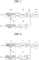
- FIG. 3 is a block diagram illustrating a conventional inverter control apparatus in which a conversion circuit section 150 and a compensation voltage calculation circuit section 160 are added to the system of FIG. 1 .
- the command voltage generation circuit section 110 determines a magnitude V ref and a phase angle ⁇ ref of an output command voltage corresponding to a command frequency ⁇ ref , and the inverter 120 synthesizes three-phase PWM voltages corresponding to the command voltage and drives the motor 130 according to the three-phase PWM voltages V as , V bs , and V cs .
- the conversion circuit section 150 converts three-phase currents of the motor 130 measured by a measurement circuit section 140 into a d-axis (a magnetic flux axis) current (in other words a magnetic flux component current) I dse and a q-axis (a torque axis) current (in other words a torque component current) I qse on a synchronous reference frame, and a compensation voltage calculation circuit section 160 determines a compensation voltage using (based upon) the q-axis current I qse .
- a magnetic flux axis a magnetic flux component current
- a torque axis a torque axis
- I qse is in-phase with the output voltage of the inverter 120 and corresponds to a torque component current proportional to load torque. Accordingly, the magnitude of the load torque can be known from the magnitude of torque component current I qse .
- Required starting torque increases as a load of the motor 130 increases. Accordingly, the compensation voltage calculation circuit section 160 compensates a voltage proportional to the torque component current I qse according to the frequency-voltage relationship of FIG. 2 to increase the starting torque.
- a load such as a fan, a pump, or a blower in which only a friction load operates upon startup has slow response characteristics, and thus there is no problem in use.
- the method is not appropriate for a system to which an instantaneous step load is applied when a system requiring large starting torque, that is, a brake is released in ascending and descending loads such as an elevator or a crane.
- the compensation voltage calculation circuit section 160 determines a compensation voltage based upon the torque component current I qse after the motor 130 is started up, and thus response characteristics for this are slowed down. Also, since appropriate voltage compensation is not achieved, an excessive current flows by a starting failure due to the insufficiency of the starting torque, which causes failures of the inverter 120 and the motor 130.
- the present invention it is possible to compensate for a voltage drop due to stator impedance and provide an inverter control apparatus having improved starting torque in a system such as an elevator or a crane requiring large starting torque and fast response characteristics when a brake is released.
- FIG. 4 is a block diagram schematically illustrating an inverter control apparatus .
- an inverter control apparatus is configured to control an inverter 2 that outputs a voltage having a predetermined magnitude and frequency to a motor 1 and may include a command voltage determination circuit section 10, an output current detection circuit section 20, a conversion circuit section 30, and a compensation voltage determination circuit section 40.
- the command voltage determination circuit section 10 can determine a magnitude V ref and a phase angle ⁇ ref of a command voltage of the inverter 2 corresponding to the command frequency ⁇ ref .
- the inverter 2 can synthesize three-phase PWM voltages V as , V bs , and V cs corresponding to the command voltage of the motor 1 based upon the magnitude V ref and phase angle ⁇ ref of the command voltage determined by the command voltage determination circuit section 10 and can drive the motor 1 according to the synthesized three-phase PWM voltages V as , V bs , and V cs .
- FIG. 5 is a diagram illustrating a frequency-voltage relationship .
- Dot line 5A in Fig. 5 shows a conventional frequency-voltage relationship of FIG. 2
- solid line 5B in Fig. 5 shows a frequency-voltage relationship.
- the command voltage determination circuit section 10 can be configured to output the magnitude of the command voltage V ref according the frequency-voltage relationship of solid line 5B such that the command frequency increases starting from zero and the magnitude of the command voltage V ref of the inverter 2 increases starting from V min .
- the output voltage which is the magnitude of the command voltage V ref of the inverter 2 may also be fixed. In this case, as shown in FIG.
- the output voltage that is the magnitude of the command voltage V ref reaches a target command voltage when the command frequency ⁇ ref reaches the target frequency. That is, upon initial startup where the command frequency ⁇ ref is zero, the command voltage is determined as being V min , but the slope in solid line 5B is more moderate than the slope in dot line 5A. Accordingly, it can be seen that the command voltage (the magnitude of the command voltage) increases with a smaller slope than a slope of the conventional case as the command frequency increases.
- the output voltage that is the initial magnitude of the command voltage V min determined by the command voltage determination circuit section 10 may be predetermined (preset) by a user according to characteristics of the motor 1.
- a trip automated circuit breaking by a circuit breaker installed between the inverter and the motor
- a load such as an elevator when an excessively low voltage is set.
- the starting failure due to the voltage drop caused by stator resistance and leakage inductance can be prohibited by the compensating voltage according to the initial magnitude of the command voltage V min , and then subsequent load compensation can be performed by the compensation voltage determination circuit section 40.
- the conversion circuit section 30 converts three-phase output currents (static reference frame currents; e.g., I as , I bs , and I cs ) of the inverter 2 measured by the output current detection circuit section 20 into a d-axis current (a magnetic flux component current) I dse and a q-axis current (torque component current) I qse on a synchronous reference frame, and the compensation voltage determination circuit section 40 can determine a compensation voltage V comp based upon the q-axis current I qse .
- I as , I bs , and I cs three-phase output currents (static reference frame currents; e.g., I as , I bs , and I cs ) of the inverter 2 measured by the output current detection circuit section 20 into a d-axis current (a magnetic flux component current) I dse and a q-axis current (torque component current) I qse on a
- the q-axis current (the torque component current) I qse is in phase with the output voltage of the inverter 2 and corresponds to a torque component current proportional to load torque. Accordingly, as described above, the magnitude of the load torque can be seen from the magnitude of the q-axis current (torque component current) I qse .
- Required starting torque increases as a load of the motor 1 increases. Accordingly, the compensation voltage determination circuit section 40 can provide a compensating voltage proportional to the torque component current I qse over the command voltage according to the frequency-voltage relationship of FIG. 5 to increase the starting torque.
- FIG. 6 is a detailed block diagram showing an example of the compensation voltage determination circuit section 40 of FIG. 4 .
- the compensation voltage determination circuit section 40 comprises a first amplifier 41, a subtractor 41-1, a comparator 42, a multiplier 43, a low pass filter (LPF) 44, and a second amplifier 45.
- the first amplifier 41 is configured to amplify a preset (predetermined) rated torque component current I qs_rate by a first gain K 1 . That is, the first amplifier 41 is configured to provide the rated torque component current I qs_rate multiplied by the first gain K 1 .
- the subtractor 41-1 is configured to subtract a rated torque component current I qs_rate multiplied by the first gain K 1 of the first amplifier 41 from the measured torque component current I qse to output a difference value.
- the subtractor 41-1 has two inputs, one of the both inputs is connected to output of the conversion circuit section 30(shown in Fig. 4 ) and the other of the both inputs is connected to output of the first amplifier 41.
- the compensation voltage determination circuit section 40 can determine whether to perform voltage compensation by means of the comparator 42 before determining the compensation voltage V comp . That is, compensation voltage determination circuit section 40 can include the multiplier 43 configured to multiply the output from the comparator 42 by the torque component current I qse to output the torque component current I qse to the LPF 44 when an output of the comparator 42 is an enable (i.e., a logic high output).
- the multiplier 43 has two inputs, one of the both inputs is connected to output of the comparator 42 and the other of the both inputs is connected to output of the conversion circuit section 30(shown in Fig. 4 ).
- the comparator 42 may compare the difference value output from the subtractor 41-1 with a low reference current value (for example zero) and may output an enable output (i.e., a logic high output) when the difference value is not less than the low reference current value.
- the comparator 42 has two inputs, one of the two inputs is connected to the subtractor 41-1 and the other of the two inputs is connected to an earth (ground) to receive a zero input value.
- the other of the both inputs in the comparator 42 is not connected to the earth(ground) but connected to other reference value input circuit section (for example an input circuit section configured with a constant current source and resistors).
- the compensation voltage determination circuit section 40 after comparing the rated torque current I qs_rate multiplied by the first gain K 1 of the first amplifier 41 with the measured torque current I qse , the compensation voltage V comp is not output upon a loadless case or a light load case(when the difference value is zero or a smaller value of the low reference current value), but is output when the torque is insufficient(when the difference value is not less than the low reference current value).
- a value smaller than 1(one) may be appropriately chosen as the first gain K 1 .
- the LPF 44 can improve stability by attenuating (removing) a ripple component from the torque component current I qse .
- An input of the LPF 44 is connected to the output of the multiplier 43, and an output of the LPF 44 is connected to an input of the second amplifier 45.
- the second amplifier 45 can multiply the torque component current I qse having passed through the LPF 44 by a second gain K 2 to output the compensation voltage V comp .
- the second gain K 2 can be preset as a value corresponds to (same as) the stator resistance. And the second gain K 2 may be preset to be different values depending on application fields (e.g., a crane, an elevator, etc.).
- the compensation voltage V comp determined by the compensation voltage determination circuit section 40 that is the compensation voltage V comp output from the second amplifier 45 can be provided to the command voltage determination circuit section 10 to be compensated for the command voltage determined by the command voltage determination circuit section 10, and the compensated command voltage can be output to the inverter 2.
- the apparatus for controlling an inverter according to present invention can perform stable startup by compensating a predetermined voltage for an insufficient voltage upon initial startup in an ascending and descending load requiring fast dynamic characteristics in order to compensate a voltage drop due to stator impedance and then can perform stable drive of the inverter by determining and compensating a compensation voltage according to a variance of the load.
Description
- The present invention relates to an inverter control apparatus.
- Generally, an inverter is a power conversion device that receives commercial alternating current (AC) power, converts the AC power into direct current (DC) power, re-converts the DC power into AC power suitable for a motor, and supplies the AC power to the motor. Such an inverter efficiently controls a motor to decrease power consumption of the motor, thereby improving energy efficiency.
- In many application loads of industrial fields, an inverter is controlled by a voltage/frequency (abbreviated as "V/F" hereinafter) control method, the control method is mainly used in fields such as a fan, a pump, and a blower that do not require fast dynamic characteristics in a driving area below a rated speed.
- Also, in an ascending/descending load such as an elevator or a crane, an encoder, which is a position sensor for measuring an absolute position of a motor or a relative position of the motor according to a rotation state of the motor, may be used to precisely control a speed and thus achieve high starting torque performance. However, in some systems, V/F control is performed due to costs incurred for maintenance of an encoder.
- However, when an inverter is controlled by V/F control, starting torque may be insufficient due to a voltage drop caused by stator resistance and leakage inductance of a motor in a slow driving area in which an output voltage of the inverter is low. Also, a starting failure due to the insufficiency of the starting torque causes an excessive current, which may cause a failure of the inverter or a failure of the motor.
-
US 2015/155815 A1 discloses an apparatus for controlling an induction machine is disclosed, wherein a magnitude of a current outputted to the induction machine to an inverter is determined by the apparatus to determine a voltage amount that compensates the command voltage in response to the magnitude of the current, and a voltage compensation amount is added to a command voltage determined from a voltage-frequency relationship according to a relevant voltage compensation amount to output a final command voltage. -
US 2003/160585 A1 discloses a motor torque control apparatus and method are disclosed. By adding the value of the compensation voltage which is obtained by proportionally integrating a difference value between the predetermined reference magnetic flux component current value and the actually measured magnetic flux component current value to the q-axis instructing voltage, the magnetic flux component current, that is, the excitation current, can be constantly controlled without excess or shortage. In addition, since the magnetic flux is constantly controlled irrespective of the speed of the motor, a high torque can be generated even at the initial stage of starting of the motor (at the low speed), and thus, the torque of the motor can be smoothly controlled in every operation range from a low speed to a high speed. - Therefore, an object of the present disclosure is to provide an inverter control apparatus for stably starting a system requiring high starting torque and fast response when a brake is released by improving an insufficiency of the starting torque due to a voltage drop upon voltage or frequency control.
- To achieve these and other advantages and in accordance with the purpose of this disclosure, as embodied and broadly described herein, there is provided an apparatus for controlling an inverter for driving a motor as defined in
independent claim 1. - According to a preferred aspect of this disclosure, the command voltage determination circuit section is configured to provide, to the inverter, a second command voltage determined by compensating the second compensation voltage to a first command voltage determined in consideration of the first compensation voltage.
- According to another preferred aspect of this disclosure, the command voltage determination circuit section is configured to fix a target command voltage and output the fixed target command voltage when a command frequency of the inverter reaches a target frequency.
- According to still another preferred aspect of this disclosure, the compensation voltage determination circuit section comprises an amplifier configured to amplify the torque component current with a gain and output the second compensation voltage, and the gain corresponds to stator resistance.
- In the drawings:
-
FIG. 1 is a block diagram schematically showing a conventional voltage/frequency control type inverter system; -
FIG. 2 is a diagram illustrating a command voltage determined according to a command frequency by a command voltage generation circuit section ofFIG. 1 ; -
FIG. 3 is a block diagram illustrating a conventional inverter control apparatus; -
FIG. 4 is a block diagram schematically illustrating an inverter control apparatus ; -
FIG. 5 is a diagram illustrating a frequency-voltage relationship ; and -
FIG. 6 is a block diagram showing detailed configuration of a compensation voltage determination circuit section ofFIG. 4 according to an embodiment of the present invention. - In order to fully understand configurations and advantageous effects of the present invention, exemplary embodiments of the present invention will be described with reference to the accompanying drawings.
- Hereinafter, a conventional inverter control apparatus and then an inverter control apparatus according to an embodiment of the present invention will be described with reference to the accompanying drawings.
-
FIG. 1 is a block diagram schematically showing a conventional voltage/frequency control type inverter system. - When a user inputs a command frequency ωref, a command voltage
generation circuit section 110 can determine a magnitude Vref and a phase angle θref of a command voltage of aninverter 120 corresponding to the command frequency ωref. Theinverter 120 synthesizes three-phase pulse width modulation (PWM) voltages Vas, Vbs, and Vcs corresponding to a command voltage of amotor 130 based upon the magnitude Vref and phase angle θref of the command voltage of theinverter 120 determined by the command voltagegeneration circuit section 110 and drives aninduction motor 130 according to the three-phase PWM voltages Vas, Vbs, and Vcs. -
FIG. 2 is an example diagram illustrating an example not part of the invention in which a command voltage is determined according to a command frequency by the command voltage generation circuit section ofFIG. 1 . It can be seen that an output frequency of theinverter 120 is proportional to an output voltage magnitude. - In
FIG. 2 , upon initial startup, the command frequency ωref increases starting from zero, and also an output voltage, the command voltage Vref of the inverter increases starting from zero according to a frequency-voltage relationship. That is, the command voltage increases proportionally as the command frequency ωref increases. When the command frequency ωref reaches a target frequency, theinverter 120 drives themotor 130 with a constant speed. - When the
motor 130 is driven as shown inFIG. 2 , an output voltage is generated in proportion to a frequency in a slow driving area upon initial startup, and thus the output voltage is low. Furthermore, a voltage needed to drive themotor 130 actually decreases due to a voltage drop caused by stator resistance and leakage inductance of themotor 130. This significantly increases a starting current and causes failures of theinverter 120 and themotor 130 and a startup failure. - In order to prevent this, the voltage should be boosted in the slow driving area in consideration of a voltage drop due to stator impedance.
-
FIG. 3 is a block diagram illustrating a conventional inverter control apparatus in which aconversion circuit section 150 and a compensation voltagecalculation circuit section 160 are added to the system ofFIG. 1 . - Like
FIG. 1 , the command voltagegeneration circuit section 110 determines a magnitude Vref and a phase angle θref of an output command voltage corresponding to a command frequency ωref, and theinverter 120 synthesizes three-phase PWM voltages corresponding to the command voltage and drives themotor 130 according to the three-phase PWM voltages Vas, Vbs, and Vcs. - The
conversion circuit section 150 converts three-phase currents of themotor 130 measured by ameasurement circuit section 140 into a d-axis (a magnetic flux axis) current (in other words a magnetic flux component current) Idse and a q-axis (a torque axis) current (in other words a torque component current) Iqse on a synchronous reference frame, and a compensation voltagecalculation circuit section 160 determines a compensation voltage using (based upon) the q-axis current Iqse. Coordinate conversion to Iqse is determined as follows:
- Iqse is in-phase with the output voltage of the
inverter 120 and corresponds to a torque component current proportional to load torque. Accordingly, the magnitude of the load torque can be known from the magnitude of torque component current Iqse. Required starting torque increases as a load of themotor 130 increases. Accordingly, the compensation voltagecalculation circuit section 160 compensates a voltage proportional to the torque component current Iqse according to the frequency-voltage relationship ofFIG. 2 to increase the starting torque. - However, according to the method, a load such as a fan, a pump, or a blower in which only a friction load operates upon startup has slow response characteristics, and thus there is no problem in use. However, the method is not appropriate for a system to which an instantaneous step load is applied when a system requiring large starting torque, that is, a brake is released in ascending and descending loads such as an elevator or a crane.
- That is, a system requiring high starting torque when a brake is released can be normally started up only when fast voltage compensation should be achieved at initial startup. However, the compensation voltage
calculation circuit section 160 determines a compensation voltage based upon the torque component current Iqse after themotor 130 is started up, and thus response characteristics for this are slowed down. Also, since appropriate voltage compensation is not achieved, an excessive current flows by a starting failure due to the insufficiency of the starting torque, which causes failures of theinverter 120 and themotor 130. - According to the present invention, it is possible to compensate for a voltage drop due to stator impedance and provide an inverter control apparatus having improved starting torque in a system such as an elevator or a crane requiring large starting torque and fast response characteristics when a brake is released.
-
FIG. 4 is a block diagram schematically illustrating an inverter control apparatus . - As shown in
FIG. 4 , an inverter control apparatus is configured to control aninverter 2 that outputs a voltage having a predetermined magnitude and frequency to amotor 1 and may include a command voltagedetermination circuit section 10, an output currentdetection circuit section 20, aconversion circuit section 30, and a compensation voltagedetermination circuit section 40. - When a user inputs a command frequency ωref through a user input unit (not shown) such as a keypad provided on a housing of the
inverter 2, the command voltagedetermination circuit section 10 can determine a magnitude Vref and a phase angle θref of a command voltage of theinverter 2 corresponding to the command frequency ωref. - The
inverter 2 can synthesize three-phase PWM voltages Vas, Vbs, and Vcs corresponding to the command voltage of themotor 1 based upon the magnitude Vref and phase angle θref of the command voltage determined by the command voltagedetermination circuit section 10 and can drive themotor 1 according to the synthesized three-phase PWM voltages Vas, Vbs, and Vcs . -
FIG. 5 is a diagram illustrating a frequency-voltage relationship .Dot line 5A inFig. 5 shows a conventional frequency-voltage relationship ofFIG. 2 , andsolid line 5B inFig. 5 shows a frequency-voltage relationship. - That is, referring to
dot line 5A, the command frequency ωref increases starting from zero, and the magnitude of the command voltage Vref of theinverter 120 also increases starting from zero. However, the command voltagedetermination circuit section 10 can be configured to output the magnitude of the command voltage Vref according the frequency-voltage relationship ofsolid line 5B such that the command frequency increases starting from zero and the magnitude of the command voltage Vref of theinverter 2 increases starting from Vmin. When the command frequency ωref reaches a target frequency, the command frequency no longer changes and the driving is performed at a constant speed. Accordingly, the output voltage, which is the magnitude of the command voltage Vref of theinverter 2, may also be fixed. In this case, as shown inFIG. 5 , it can be seen that the output voltage, that is the magnitude of the command voltage Vref reaches a target command voltage when the command frequency ωref reaches the target frequency. That is, upon initial startup where the command frequency ωref is zero, the command voltage is determined as being Vmin, but the slope insolid line 5B is more moderate than the slope indot line 5A. Accordingly, it can be seen that the command voltage (the magnitude of the command voltage) increases with a smaller slope than a slope of the conventional case as the command frequency increases. - When the command frequency ωref is zero, the output voltage, that is the initial magnitude of the command voltage Vmin determined by the command voltage
determination circuit section 10 may be predetermined (preset) by a user according to characteristics of themotor 1. In this case, a trip (automatic circuit breaking by a circuit breaker installed between the inverter and the motor) may occur when an excessively high voltage as the initial magnitude of the command voltage Vmin is set, and it becomes impossible to move a load such as an elevator when an excessively low voltage is set. - Accordingly, when the
motor 1 is driven, the starting failure due to the voltage drop caused by stator resistance and leakage inductance can be prohibited by the compensating voltage according to the initial magnitude of the command voltage Vmin, and then subsequent load compensation can be performed by the compensation voltagedetermination circuit section 40. - The
conversion circuit section 30 converts three-phase output currents (static reference frame currents; e.g., Ias, Ibs, and Ics) of theinverter 2 measured by the output currentdetection circuit section 20 into a d-axis current (a magnetic flux component current) Idse and a q-axis current (torque component current) Iqse on a synchronous reference frame, and the compensation voltagedetermination circuit section 40 can determine a compensation voltage Vcomp based upon the q-axis current Iqse. - The q-axis current (the torque component current) Iqse is in phase with the output voltage of the
inverter 2 and corresponds to a torque component current proportional to load torque. Accordingly, as described above, the magnitude of the load torque can be seen from the magnitude of the q-axis current (torque component current) Iqse. Required starting torque increases as a load of themotor 1 increases. Accordingly, the compensation voltagedetermination circuit section 40 can provide a compensating voltage proportional to the torque component current Iqse over the command voltage according to the frequency-voltage relationship ofFIG. 5 to increase the starting torque. -
FIG. 6 is a detailed block diagram showing an example of the compensation voltagedetermination circuit section 40 ofFIG. 4 . - As shown in
FIG. 6 , the compensation voltagedetermination circuit section 40 according to the present invention comprises afirst amplifier 41, a subtractor 41-1, acomparator 42, amultiplier 43, a low pass filter (LPF) 44, and asecond amplifier 45. - The
first amplifier 41 is configured to amplify a preset (predetermined) rated torque component current Iqs_rate by a first gain K1. That is, thefirst amplifier 41 is configured to provide the rated torque component current Iqs_rate multiplied by the first gain K1. - The subtractor 41-1 is configured to subtract a rated torque component current Iqs_rate multiplied by the first gain K1 of the
first amplifier 41 from the measured torque component current Iqse to output a difference value. - The subtractor 41-1 has two inputs, one of the both inputs is connected to output of the conversion circuit section 30(shown in
Fig. 4 ) and the other of the both inputs is connected to output of thefirst amplifier 41. - The compensation voltage
determination circuit section 40 according to an embodiment of the present invention can determine whether to perform voltage compensation by means of thecomparator 42 before determining the compensation voltage Vcomp. That is, compensation voltagedetermination circuit section 40 can include themultiplier 43 configured to multiply the output from thecomparator 42 by the torque component current Iqse to output the torque component current Iqse to theLPF 44 when an output of thecomparator 42 is an enable (i.e., a logic high output). - The
multiplier 43 has two inputs, one of the both inputs is connected to output of thecomparator 42 and the other of the both inputs is connected to output of the conversion circuit section 30(shown inFig. 4 ). - The
comparator 42 may compare the difference value output from the subtractor 41-1 with a low reference current value (for example zero) and may output an enable output (i.e., a logic high output) when the difference value is not less than the low reference current value. - The
comparator 42 has two inputs, one of the two inputs is connected to the subtractor 41-1 and the other of the two inputs is connected to an earth (ground) to receive a zero input value. - According to another preferred embodiment, the other of the both inputs in the
comparator 42 is not connected to the earth(ground) but connected to other reference value input circuit section (for example an input circuit section configured with a constant current source and resistors). - As described as above, by the compensation voltage
determination circuit section 40 according to an embodiment of the present invention, after comparing the rated torque current Iqs_rate multiplied by the first gain K1 of thefirst amplifier 41 with the measured torque current Iqse, the compensation voltage Vcomp is not output upon a loadless case or a light load case(when the difference value is zero or a smaller value of the low reference current value), but is output when the torque is insufficient(when the difference value is not less than the low reference current value). - A value smaller than 1(one) may be appropriately chosen as the first gain K1.
- The
LPF 44 can improve stability by attenuating (removing) a ripple component from the torque component current Iqse. - An input of the
LPF 44 is connected to the output of themultiplier 43, and an output of theLPF 44 is connected to an input of thesecond amplifier 45. - The
second amplifier 45 can multiply the torque component current Iqse having passed through theLPF 44 by a second gain K2 to output the compensation voltage Vcomp. According to a preferred aspect of the present invention, the second gain K2 can be preset as a value corresponds to (same as) the stator resistance. And the second gain K2 may be preset to be different values depending on application fields (e.g., a crane, an elevator, etc.). - The compensation voltage Vcomp determined by the compensation voltage
determination circuit section 40, that is the compensation voltage Vcomp output from thesecond amplifier 45 can be provided to the command voltagedetermination circuit section 10 to be compensated for the command voltage determined by the command voltagedetermination circuit section 10, and the compensated command voltage can be output to theinverter 2. - As described as above, the apparatus for controlling an inverter according to present invention can perform stable startup by compensating a predetermined voltage for an insufficient voltage upon initial startup in an ascending and descending load requiring fast dynamic characteristics in order to compensate a voltage drop due to stator impedance and then can perform stable drive of the inverter by determining and compensating a compensation voltage according to a variance of the load.
Claims (4)
- An apparatus for controlling an inverter for driving a motor, wherein the apparatus comprises:a command voltage determination circuit section (10) that determines a predetermined first compensation voltage (Vmin) as a command voltage (Vref) upon initial startup and provides the command voltage (Vref) to the inverter (2);a conversion circuit section (30) that converts an output current of the inverter (2) into a torque component current (Iqse) on a synchronous reference frame; anda compensation voltage determination circuit section (40) that determines a second compensation voltage (Vcomp) based upon the torque component current (Iqse) and provides the second compensation voltage (Vcomp) to the command voltage determination circuit section (10),characterized in thatthe compensation voltage determination circuit section (40) comprises:a first amplifier (41) that amplifies a predetermined rated torque component current by a first gain (K1) to output the amplified rated torque component current (Iqs_rate);a subtractor (41-1) that subtracts the amplified rated torque component current (Iqs rate) output from the first amplifier (41) from the torque component current (Iqse);a comparator (42) that compares an output of the subtractor (41-1) with a predetermined reference current value to output a logic high output when the output of the subtractor (41-1) is not less than the predetermined reference current value;a multiplier (43) that multiplies the output from the comparator (42) by the torque component current to output the torque component current when an output of the comparator (42) is a logic high output;a low pass filter (44) that attenuates a ripple component of the torque component current to output the torque component current from which ripple component is removed; anda second amplifier (45) that amplifies the torque component current output from the low pass filter (44) with a second gain (K2) and outputs the amplified torque component current as the second compensation voltage.
- The apparatus of claim 1, wherein the command voltage determination circuit section (10) is configured to provide, to the inverter (2), with a second command voltage determined by compensating the second compensation voltage to a first command voltage determined in consideration of the first compensation voltage (Vmin).
- The apparatus of claim 1 or 2, wherein the command voltage determination circuit section (10) is configured to fix a target command voltage and output the fixed target command voltage when a command frequency of the inverter (2) reaches a target frequency.
- The apparatus of any one of claims 1-3, wherein the compensation voltage determination circuit section (40) comprises an amplifier (45) configured to amplify the torque component current with a gain (K2) and output the second compensation voltage, and the gain (K2) corresponds to stator resistance.
Applications Claiming Priority (1)
| Application Number | Priority Date | Filing Date | Title |
|---|---|---|---|
| KR1020170028277A KR102036031B1 (en) | 2017-03-06 | 2017-03-06 | Apparatus for controlling inverter |
Publications (2)
| Publication Number | Publication Date |
|---|---|
| EP3373442A1 EP3373442A1 (en) | 2018-09-12 |
| EP3373442B1 true EP3373442B1 (en) | 2021-12-15 |
Family
ID=60452461
Family Applications (1)
| Application Number | Title | Priority Date | Filing Date |
|---|---|---|---|
| EP17203269.0A Active EP3373442B1 (en) | 2017-03-06 | 2017-11-23 | Inverter control apparatus |
Country Status (6)
| Country | Link |
|---|---|
| US (1) | US10411630B2 (en) |
| EP (1) | EP3373442B1 (en) |
| JP (1) | JP2018148779A (en) |
| KR (1) | KR102036031B1 (en) |
| CN (1) | CN108540039B (en) |
| ES (1) | ES2905659T3 (en) |
Families Citing this family (2)
| Publication number | Priority date | Publication date | Assignee | Title |
|---|---|---|---|---|
| DE102017001238A1 (en) * | 2017-02-09 | 2018-08-09 | Liebherr-Components Biberach Gmbh | Hoist and method for starting the hoist of such a hoist |
| CN113036740A (en) * | 2019-12-24 | 2021-06-25 | 北京金风科创风电设备有限公司 | Converter brake control method and device of wind generating set |
Family Cites Families (14)
| Publication number | Priority date | Publication date | Assignee | Title |
|---|---|---|---|---|
| JP2596521Y2 (en) * | 1992-09-28 | 1999-06-14 | 東洋電機製造株式会社 | Motor start compensation device |
| JPH07107781A (en) | 1993-09-30 | 1995-04-21 | Fuji Electric Co Ltd | Control circuit of v/f control inverter |
| JP3289568B2 (en) * | 1995-09-01 | 2002-06-10 | 富士電機株式会社 | Induction motor control device |
| JP3635887B2 (en) | 1997-09-29 | 2005-04-06 | 株式会社明電舎 | Torque boost method for inverter device |
| JP3918148B2 (en) | 2001-07-24 | 2007-05-23 | 株式会社日立製作所 | Inverter device |
| KR100442494B1 (en) * | 2002-02-26 | 2004-07-30 | 엘지산전 주식회사 | Control method and controller for torque of inverter |
| JP4298448B2 (en) * | 2003-09-18 | 2009-07-22 | 東芝エレベータ株式会社 | Escalator control device |
| JP4519864B2 (en) * | 2007-01-29 | 2010-08-04 | 三菱電機株式会社 | AC rotating machine electrical constant measuring method and AC rotating machine control apparatus used for carrying out this measuring method |
| KR100967665B1 (en) * | 2008-04-01 | 2010-07-07 | 부산대학교 산학협력단 | System and method for motor speed control in the low speed region |
| CN101674043A (en) * | 2008-09-10 | 2010-03-17 | 上海山宇电子设备有限公司 | Method for controlling vector frequency converter of rotor field-oriented speed sensor-less |
| KR101535727B1 (en) * | 2013-11-29 | 2015-07-09 | 엘에스산전 주식회사 | Apparatus for controlling induction machine |
| KR101827042B1 (en) * | 2014-11-12 | 2018-03-22 | 엘에스산전 주식회사 | Apparatus for controlling inverter |
| KR101750609B1 (en) | 2015-03-10 | 2017-06-23 | 엘에스산전 주식회사 | An inverter for supplying load-adaptive boost voltage |
| WO2017006485A1 (en) * | 2015-07-09 | 2017-01-12 | 三菱電機株式会社 | Motor control device |
-
2017
- 2017-03-06 KR KR1020170028277A patent/KR102036031B1/en active IP Right Grant
- 2017-11-23 EP EP17203269.0A patent/EP3373442B1/en active Active
- 2017-11-23 ES ES17203269T patent/ES2905659T3/en active Active
- 2017-12-13 CN CN201711328283.2A patent/CN108540039B/en active Active
- 2017-12-21 JP JP2017245230A patent/JP2018148779A/en active Pending
-
2018
- 2018-01-05 US US15/863,248 patent/US10411630B2/en active Active
Non-Patent Citations (1)
| Title |
|---|
| None * |
Also Published As
| Publication number | Publication date |
|---|---|
| JP2018148779A (en) | 2018-09-20 |
| CN108540039A (en) | 2018-09-14 |
| ES2905659T3 (en) | 2022-04-11 |
| US20180254729A1 (en) | 2018-09-06 |
| US10411630B2 (en) | 2019-09-10 |
| KR102036031B1 (en) | 2019-10-25 |
| EP3373442A1 (en) | 2018-09-12 |
| KR20180101837A (en) | 2018-09-14 |
| CN108540039B (en) | 2021-11-02 |
Similar Documents
| Publication | Publication Date | Title |
|---|---|---|
| KR940006168B1 (en) | Device for controlling an ac motor | |
| US7791911B2 (en) | Inverter device which maintains voltage during input voltage drop | |
| US6264005B1 (en) | Method for controlling rescue operation of elevator car during power failure | |
| US9178458B2 (en) | Controller of AC motor | |
| US9160262B2 (en) | Sensorless motor control | |
| US20140197774A1 (en) | Method and apparatus for controlling power converter with inverter output filter | |
| US20080315824A1 (en) | Induction motor drive unit, motor drive system, and elevating system | |
| EP3373442B1 (en) | Inverter control apparatus | |
| EP3358743A1 (en) | Power conversion device and auto-tuning method therefor | |
| EP2879290B1 (en) | Apparatus for controlling induction motor | |
| EP1536552B1 (en) | Ac generator sensor-less vector control method and control device thereof | |
| EP3021479B1 (en) | Apparatus for controlling inverter | |
| EP2357724B1 (en) | Motor control system for a hoist drive | |
| EP3883123B1 (en) | Motor control device | |
| JP2003088194A (en) | Motor drive system | |
| EP1659684B1 (en) | Controller of rotating machine | |
| EP3229364B1 (en) | Inverter | |
| EP3214753A1 (en) | Power conversion device and method for controlling power conversion device | |
| KR100304790B1 (en) | Apparatus for controlling speed of motor | |
| JP3323900B2 (en) | Control device for linear motor electric vehicle | |
| JP2000197399A (en) | Elevator controller | |
| JP2022121778A (en) | Control device for high efficiency operation and control method for high efficiency operation of permanent magnet synchronous motor |
Legal Events
| Date | Code | Title | Description |
|---|---|---|---|
| PUAI | Public reference made under article 153(3) epc to a published international application that has entered the european phase |
Free format text: ORIGINAL CODE: 0009012 |
|
| STAA | Information on the status of an ep patent application or granted ep patent |
Free format text: STATUS: THE APPLICATION HAS BEEN PUBLISHED |
|
| AK | Designated contracting states |
Kind code of ref document: A1 Designated state(s): AL AT BE BG CH CY CZ DE DK EE ES FI FR GB GR HR HU IE IS IT LI LT LU LV MC MK MT NL NO PL PT RO RS SE SI SK SM TR |
|
| AX | Request for extension of the european patent |
Extension state: BA ME |
|
| STAA | Information on the status of an ep patent application or granted ep patent |
Free format text: STATUS: REQUEST FOR EXAMINATION WAS MADE |
|
| 17P | Request for examination filed |
Effective date: 20190311 |
|
| RBV | Designated contracting states (corrected) |
Designated state(s): AL AT BE BG CH CY CZ DE DK EE ES FI FR GB GR HR HU IE IS IT LI LT LU LV MC MK MT NL NO PL PT RO RS SE SI SK SM TR |
|
| STAA | Information on the status of an ep patent application or granted ep patent |
Free format text: STATUS: EXAMINATION IS IN PROGRESS |
|
| 17Q | First examination report despatched |
Effective date: 20200605 |
|
| STAA | Information on the status of an ep patent application or granted ep patent |
Free format text: STATUS: EXAMINATION IS IN PROGRESS |
|
| GRAP | Despatch of communication of intention to grant a patent |
Free format text: ORIGINAL CODE: EPIDOSNIGR1 |
|
| STAA | Information on the status of an ep patent application or granted ep patent |
Free format text: STATUS: GRANT OF PATENT IS INTENDED |
|
| INTG | Intention to grant announced |
Effective date: 20210624 |
|
| GRAS | Grant fee paid |
Free format text: ORIGINAL CODE: EPIDOSNIGR3 |
|
| GRAA | (expected) grant |
Free format text: ORIGINAL CODE: 0009210 |
|
| STAA | Information on the status of an ep patent application or granted ep patent |
Free format text: STATUS: THE PATENT HAS BEEN GRANTED |
|
| AK | Designated contracting states |
Kind code of ref document: B1 Designated state(s): AL AT BE BG CH CY CZ DE DK EE ES FI FR GB GR HR HU IE IS IT LI LT LU LV MC MK MT NL NO PL PT RO RS SE SI SK SM TR |
|
| REG | Reference to a national code |
Ref country code: GB Ref legal event code: FG4D Ref country code: CH Ref legal event code: EP |
|
| REG | Reference to a national code |
Ref country code: DE Ref legal event code: R096 Ref document number: 602017050876 Country of ref document: DE |
|
| REG | Reference to a national code |
Ref country code: IE Ref legal event code: FG4D |
|
| REG | Reference to a national code |
Ref country code: AT Ref legal event code: REF Ref document number: 1456231 Country of ref document: AT Kind code of ref document: T Effective date: 20220115 |
|
| REG | Reference to a national code |
Ref country code: LT Ref legal event code: MG9D Ref country code: ES Ref legal event code: FG2A Ref document number: 2905659 Country of ref document: ES Kind code of ref document: T3 Effective date: 20220411 |
|
| REG | Reference to a national code |
Ref country code: NL Ref legal event code: MP Effective date: 20211215 |
|
| PG25 | Lapsed in a contracting state [announced via postgrant information from national office to epo] |
Ref country code: RS Free format text: LAPSE BECAUSE OF FAILURE TO SUBMIT A TRANSLATION OF THE DESCRIPTION OR TO PAY THE FEE WITHIN THE PRESCRIBED TIME-LIMIT Effective date: 20211215 Ref country code: LT Free format text: LAPSE BECAUSE OF FAILURE TO SUBMIT A TRANSLATION OF THE DESCRIPTION OR TO PAY THE FEE WITHIN THE PRESCRIBED TIME-LIMIT Effective date: 20211215 Ref country code: FI Free format text: LAPSE BECAUSE OF FAILURE TO SUBMIT A TRANSLATION OF THE DESCRIPTION OR TO PAY THE FEE WITHIN THE PRESCRIBED TIME-LIMIT Effective date: 20211215 Ref country code: BG Free format text: LAPSE BECAUSE OF FAILURE TO SUBMIT A TRANSLATION OF THE DESCRIPTION OR TO PAY THE FEE WITHIN THE PRESCRIBED TIME-LIMIT Effective date: 20220315 |
|
| REG | Reference to a national code |
Ref country code: AT Ref legal event code: MK05 Ref document number: 1456231 Country of ref document: AT Kind code of ref document: T Effective date: 20211215 |
|
| PG25 | Lapsed in a contracting state [announced via postgrant information from national office to epo] |
Ref country code: SE Free format text: LAPSE BECAUSE OF FAILURE TO SUBMIT A TRANSLATION OF THE DESCRIPTION OR TO PAY THE FEE WITHIN THE PRESCRIBED TIME-LIMIT Effective date: 20211215 Ref country code: NO Free format text: LAPSE BECAUSE OF FAILURE TO SUBMIT A TRANSLATION OF THE DESCRIPTION OR TO PAY THE FEE WITHIN THE PRESCRIBED TIME-LIMIT Effective date: 20220315 Ref country code: LV Free format text: LAPSE BECAUSE OF FAILURE TO SUBMIT A TRANSLATION OF THE DESCRIPTION OR TO PAY THE FEE WITHIN THE PRESCRIBED TIME-LIMIT Effective date: 20211215 Ref country code: HR Free format text: LAPSE BECAUSE OF FAILURE TO SUBMIT A TRANSLATION OF THE DESCRIPTION OR TO PAY THE FEE WITHIN THE PRESCRIBED TIME-LIMIT Effective date: 20211215 Ref country code: GR Free format text: LAPSE BECAUSE OF FAILURE TO SUBMIT A TRANSLATION OF THE DESCRIPTION OR TO PAY THE FEE WITHIN THE PRESCRIBED TIME-LIMIT Effective date: 20220316 |
|
| PG25 | Lapsed in a contracting state [announced via postgrant information from national office to epo] |
Ref country code: NL Free format text: LAPSE BECAUSE OF FAILURE TO SUBMIT A TRANSLATION OF THE DESCRIPTION OR TO PAY THE FEE WITHIN THE PRESCRIBED TIME-LIMIT Effective date: 20211215 |
|
| PG25 | Lapsed in a contracting state [announced via postgrant information from national office to epo] |
Ref country code: SM Free format text: LAPSE BECAUSE OF FAILURE TO SUBMIT A TRANSLATION OF THE DESCRIPTION OR TO PAY THE FEE WITHIN THE PRESCRIBED TIME-LIMIT Effective date: 20211215 Ref country code: SK Free format text: LAPSE BECAUSE OF FAILURE TO SUBMIT A TRANSLATION OF THE DESCRIPTION OR TO PAY THE FEE WITHIN THE PRESCRIBED TIME-LIMIT Effective date: 20211215 Ref country code: RO Free format text: LAPSE BECAUSE OF FAILURE TO SUBMIT A TRANSLATION OF THE DESCRIPTION OR TO PAY THE FEE WITHIN THE PRESCRIBED TIME-LIMIT Effective date: 20211215 Ref country code: PT Free format text: LAPSE BECAUSE OF FAILURE TO SUBMIT A TRANSLATION OF THE DESCRIPTION OR TO PAY THE FEE WITHIN THE PRESCRIBED TIME-LIMIT Effective date: 20220418 Ref country code: EE Free format text: LAPSE BECAUSE OF FAILURE TO SUBMIT A TRANSLATION OF THE DESCRIPTION OR TO PAY THE FEE WITHIN THE PRESCRIBED TIME-LIMIT Effective date: 20211215 Ref country code: CZ Free format text: LAPSE BECAUSE OF FAILURE TO SUBMIT A TRANSLATION OF THE DESCRIPTION OR TO PAY THE FEE WITHIN THE PRESCRIBED TIME-LIMIT Effective date: 20211215 |
|
| PG25 | Lapsed in a contracting state [announced via postgrant information from national office to epo] |
Ref country code: PL Free format text: LAPSE BECAUSE OF FAILURE TO SUBMIT A TRANSLATION OF THE DESCRIPTION OR TO PAY THE FEE WITHIN THE PRESCRIBED TIME-LIMIT Effective date: 20211215 Ref country code: AT Free format text: LAPSE BECAUSE OF FAILURE TO SUBMIT A TRANSLATION OF THE DESCRIPTION OR TO PAY THE FEE WITHIN THE PRESCRIBED TIME-LIMIT Effective date: 20211215 |
|
| REG | Reference to a national code |
Ref country code: DE Ref legal event code: R097 Ref document number: 602017050876 Country of ref document: DE |
|
| PG25 | Lapsed in a contracting state [announced via postgrant information from national office to epo] |
Ref country code: IS Free format text: LAPSE BECAUSE OF FAILURE TO SUBMIT A TRANSLATION OF THE DESCRIPTION OR TO PAY THE FEE WITHIN THE PRESCRIBED TIME-LIMIT Effective date: 20220415 |
|
| PLBE | No opposition filed within time limit |
Free format text: ORIGINAL CODE: 0009261 |
|
| STAA | Information on the status of an ep patent application or granted ep patent |
Free format text: STATUS: NO OPPOSITION FILED WITHIN TIME LIMIT |
|
| PG25 | Lapsed in a contracting state [announced via postgrant information from national office to epo] |
Ref country code: DK Free format text: LAPSE BECAUSE OF FAILURE TO SUBMIT A TRANSLATION OF THE DESCRIPTION OR TO PAY THE FEE WITHIN THE PRESCRIBED TIME-LIMIT Effective date: 20211215 Ref country code: AL Free format text: LAPSE BECAUSE OF FAILURE TO SUBMIT A TRANSLATION OF THE DESCRIPTION OR TO PAY THE FEE WITHIN THE PRESCRIBED TIME-LIMIT Effective date: 20211215 |
|
| PGFP | Annual fee paid to national office [announced via postgrant information from national office to epo] |
Ref country code: GB Payment date: 20220905 Year of fee payment: 6 |
|
| 26N | No opposition filed |
Effective date: 20220916 |
|
| PG25 | Lapsed in a contracting state [announced via postgrant information from national office to epo] |
Ref country code: SI Free format text: LAPSE BECAUSE OF FAILURE TO SUBMIT A TRANSLATION OF THE DESCRIPTION OR TO PAY THE FEE WITHIN THE PRESCRIBED TIME-LIMIT Effective date: 20211215 |
|
| PGFP | Annual fee paid to national office [announced via postgrant information from national office to epo] |
Ref country code: ES Payment date: 20221209 Year of fee payment: 6 |
|
| PG25 | Lapsed in a contracting state [announced via postgrant information from national office to epo] |
Ref country code: MC Free format text: LAPSE BECAUSE OF FAILURE TO SUBMIT A TRANSLATION OF THE DESCRIPTION OR TO PAY THE FEE WITHIN THE PRESCRIBED TIME-LIMIT Effective date: 20211215 |
|
| REG | Reference to a national code |
Ref country code: CH Ref legal event code: PL |
|
| REG | Reference to a national code |
Ref country code: BE Ref legal event code: MM Effective date: 20221130 |
|
| PG25 | Lapsed in a contracting state [announced via postgrant information from national office to epo] |
Ref country code: LI Free format text: LAPSE BECAUSE OF NON-PAYMENT OF DUE FEES Effective date: 20221130 Ref country code: CH Free format text: LAPSE BECAUSE OF NON-PAYMENT OF DUE FEES Effective date: 20221130 |
|
| P01 | Opt-out of the competence of the unified patent court (upc) registered |
Effective date: 20230625 |
|
| PG25 | Lapsed in a contracting state [announced via postgrant information from national office to epo] |
Ref country code: LU Free format text: LAPSE BECAUSE OF NON-PAYMENT OF DUE FEES Effective date: 20221123 |
|
| PG25 | Lapsed in a contracting state [announced via postgrant information from national office to epo] |
Ref country code: IE Free format text: LAPSE BECAUSE OF NON-PAYMENT OF DUE FEES Effective date: 20221123 |
|
| PGFP | Annual fee paid to national office [announced via postgrant information from national office to epo] |
Ref country code: IT Payment date: 20230906 Year of fee payment: 7 |
|
| PG25 | Lapsed in a contracting state [announced via postgrant information from national office to epo] |
Ref country code: FR Free format text: LAPSE BECAUSE OF NON-PAYMENT OF DUE FEES Effective date: 20221130 Ref country code: BE Free format text: LAPSE BECAUSE OF NON-PAYMENT OF DUE FEES Effective date: 20221130 |
|
| PGFP | Annual fee paid to national office [announced via postgrant information from national office to epo] |
Ref country code: DE Payment date: 20230905 Year of fee payment: 7 |
|
| PG25 | Lapsed in a contracting state [announced via postgrant information from national office to epo] |
Ref country code: HU Free format text: LAPSE BECAUSE OF FAILURE TO SUBMIT A TRANSLATION OF THE DESCRIPTION OR TO PAY THE FEE WITHIN THE PRESCRIBED TIME-LIMIT; INVALID AB INITIO Effective date: 20171123 |