EP3373251A1 - Scan-kolorierung mit einer unkalibrierten kamera - Google Patents
Scan-kolorierung mit einer unkalibrierten kamera Download PDFInfo
- Publication number
- EP3373251A1 EP3373251A1 EP18305240.6A EP18305240A EP3373251A1 EP 3373251 A1 EP3373251 A1 EP 3373251A1 EP 18305240 A EP18305240 A EP 18305240A EP 3373251 A1 EP3373251 A1 EP 3373251A1
- Authority
- EP
- European Patent Office
- Prior art keywords
- camera
- point cloud
- image
- point
- depth
- Prior art date
- Legal status (The legal status is an assumption and is not a legal conclusion. Google has not performed a legal analysis and makes no representation as to the accuracy of the status listed.)
- Pending
Links
Images


Classifications
-
- H—ELECTRICITY
- H04—ELECTRIC COMMUNICATION TECHNIQUE
- H04N—PICTORIAL COMMUNICATION, e.g. TELEVISION
- H04N13/00—Stereoscopic video systems; Multi-view video systems; Details thereof
- H04N13/10—Processing, recording or transmission of stereoscopic or multi-view image signals
- H04N13/106—Processing image signals
- H04N13/15—Processing image signals for colour aspects of image signals
-
- G—PHYSICS
- G06—COMPUTING; CALCULATING OR COUNTING
- G06T—IMAGE DATA PROCESSING OR GENERATION, IN GENERAL
- G06T19/00—Manipulating 3D models or images for computer graphics
- G06T19/20—Editing of 3D images, e.g. changing shapes or colours, aligning objects or positioning parts
-
- G—PHYSICS
- G06—COMPUTING; CALCULATING OR COUNTING
- G06T—IMAGE DATA PROCESSING OR GENERATION, IN GENERAL
- G06T15/00—3D [Three Dimensional] image rendering
- G06T15/10—Geometric effects
- G06T15/20—Perspective computation
-
- G—PHYSICS
- G06—COMPUTING; CALCULATING OR COUNTING
- G06T—IMAGE DATA PROCESSING OR GENERATION, IN GENERAL
- G06T7/00—Image analysis
- G06T7/50—Depth or shape recovery
- G06T7/55—Depth or shape recovery from multiple images
-
- G—PHYSICS
- G06—COMPUTING; CALCULATING OR COUNTING
- G06T—IMAGE DATA PROCESSING OR GENERATION, IN GENERAL
- G06T7/00—Image analysis
- G06T7/70—Determining position or orientation of objects or cameras
-
- H—ELECTRICITY
- H04—ELECTRIC COMMUNICATION TECHNIQUE
- H04N—PICTORIAL COMMUNICATION, e.g. TELEVISION
- H04N13/00—Stereoscopic video systems; Multi-view video systems; Details thereof
- H04N13/20—Image signal generators
- H04N13/271—Image signal generators wherein the generated image signals comprise depth maps or disparity maps
-
- G—PHYSICS
- G06—COMPUTING; CALCULATING OR COUNTING
- G06T—IMAGE DATA PROCESSING OR GENERATION, IN GENERAL
- G06T2207/00—Indexing scheme for image analysis or image enhancement
- G06T2207/10—Image acquisition modality
- G06T2207/10028—Range image; Depth image; 3D point clouds
-
- G—PHYSICS
- G06—COMPUTING; CALCULATING OR COUNTING
- G06T—IMAGE DATA PROCESSING OR GENERATION, IN GENERAL
- G06T2207/00—Indexing scheme for image analysis or image enhancement
- G06T2207/30—Subject of image; Context of image processing
- G06T2207/30244—Camera pose
-
- G—PHYSICS
- G06—COMPUTING; CALCULATING OR COUNTING
- G06T—IMAGE DATA PROCESSING OR GENERATION, IN GENERAL
- G06T2219/00—Indexing scheme for manipulating 3D models or images for computer graphics
- G06T2219/20—Indexing scheme for editing of 3D models
- G06T2219/2012—Colour editing, changing, or manipulating; Use of colour codes
-
- H—ELECTRICITY
- H04—ELECTRIC COMMUNICATION TECHNIQUE
- H04N—PICTORIAL COMMUNICATION, e.g. TELEVISION
- H04N13/00—Stereoscopic video systems; Multi-view video systems; Details thereof
- H04N2013/0074—Stereoscopic image analysis
- H04N2013/0077—Colour aspects
-
- H—ELECTRICITY
- H04—ELECTRIC COMMUNICATION TECHNIQUE
- H04N—PICTORIAL COMMUNICATION, e.g. TELEVISION
- H04N13/00—Stereoscopic video systems; Multi-view video systems; Details thereof
- H04N2013/0074—Stereoscopic image analysis
- H04N2013/0081—Depth or disparity estimation from stereoscopic image signals
Definitions
- Embodiments described herein relate generally to colorizing three-dimensional (3D) point clouds, and more particularly, to colorizing 3D point clouds acquired by a 3D scanning device using color images acquired by an uncalibrated camera.
- a 3D point cloud may include X, Y, and Z coordinates of a set of points in a 3D coordinate system. These points are often intended to represent the external surfaces of objects. 3D point clouds can be acquired by 3D scanners, stereo vision cameras, time-of-flight lidar systems, and the like.
- 3D data are becoming mainstream in many applications, such as urban analysis, building monitoring, industrial modeling, digital terrain generation, forest monitoring, documentation of cultural heritage, among others.
- Visualizing and inspecting 3D point clouds acquired by 3D scanning devices can be challenging, especially for non-expert users.
- scanning device manufacturers may use photographs to colorize the point clouds.
- colors from photographic images are assigned to the corresponding points in a point cloud.
- a method of colorizing a 3D point cloud includes receiving the 3D point cloud.
- the 3D point cloud can be acquired by a 3D imaging device positioned at a first location.
- the 3D point cloud can include 3D coordinates and intensity data for a set of points representing surfaces of one or more objects.
- the method further includes receiving a 2D color image of the one or more objects acquired by a camera positioned at an approximately known second location and an approximately known orientation.
- the camera has an approximately known set of intrinsic optical parameter.
- the method further includes creating a 2D intensity image of the 3D point cloud using the intensity data by projecting the 3D point cloud onto a 2D image area from a view point of the second location based on the set of intrinsic optical parameters, the second location, and the orientation of the camera.
- the 2D image area can have a size that is the same as the size of the 2D color image.
- the method further includes generating a set of refined camera parameters for projecting the 3D point cloud onto the 2D image area by matching the 2D intensity image and the 2D color image.
- the method further includes creating a depth buffer for the 3D point cloud.
- the depth buffer can have an image area of a size that is the same as the size of the 2D color image and a pixel size that is the same as the pixel size of the 2D color image.
- the depth buffer includes depth data for the set of points in the 3D point cloud as the set of points are projected onto pixels of the depth buffer using the set of refined camera parameters.
- the method further includes determining a foreground depth for each respective pixel of the depth buffer by detecting a closest point among a subset of the set of points corresponding to the respective pixel.
- the method further includes coloring the point cloud by, for each respective point of the set of points: comparing a depth of the respective point with a foreground depth of a corresponding pixel in the depth buffer; upon determining that the depth of the respective point is within a predetermined threshold value from the foreground depth of the corresponding pixel, assigning a color of a corresponding pixel in the 2D color image to the respective point; and upon determining that the depth of the respective point differs from the foreground depth of the corresponding pixel by an amount greater than the predetermined threshold value, not assigning any color to the respective point.
- a method of camera calibration with respect to a 3D imaging device includes receiving a 3D point cloud acquired by the 3D imaging device positioned at a first location.
- the 3D point cloud can include 3D coordinates and intensity data for a set of points representing surfaces of one or more objects.
- the method further includes receiving a 2D color image of the one or more objects acquired by a camera positioned at an approximately known second location and an approximately known orientation.
- the camera can have an approximately known set of intrinsic optical parameters.
- the method further includes creating a 2D intensity image of the 3D point cloud using the intensity data by projecting the 3D point cloud onto a 2D image area from a view point of the second location based on the set of intrinsic optical parameters of the camera, the second location, and the orientation of the camera.
- the 2D image area can have a size that is the same as the size of the 2D color image.
- the method further includes performing image matching between the 2D intensity image and the 2D color image to generate a set of refined camera parameters for projecting the 3D point cloud onto the 2D image area.
- a method of camera calibration with respect to a 3D imaging device includes receiving a 3D point cloud acquired by the 3D imaging device.
- the 3D point cloud can include 3D coordinates and intensity data for a set of points representing surfaces of one or more objects.
- the method further includes receiving a plurality of two-dimensional (2D) color images of the one or more objects acquired by a camera positioned at a plurality of corresponding locations and a plurality of corresponding orientations.
- the camera can have an approximately known set of intrinsic optical parameters.
- the method further includes generating a plurality of sets of refined camera parameters by, for each respective 2D color image of the plurality of 2D color images: creating a respective 2D intensity image of the 3D point cloud using the intensity data by projecting the 3D point cloud onto a 2D image area from a view point of the camera based on a respective location and respective orientation, and the set of intrinsic optical parameters of the camera, the 2D image area having a size that is the same as the size of the 2D color image; and performing image matching between the respective 2D intensity image and the respective 2D color image to generate a respective set of refined camera parameters for projecting the 3D point cloud onto the 2D image area.
- the method further includes selecting one set of the refined camera parameters from the plurality of sets of refined camera parameters as a final set of refined camera parameters.
- a method of colorizing a 3D point cloud includes receiving the 3D point cloud.
- the 3D point cloud can be acquired by a 3D imaging device positioned at a first location.
- the 3D point cloud can include 3D coordinates for a set of points representing surfaces of one or more objects.
- the method further includes receiving a 2D color image of the one or more objects acquired by a camera positioned at a second location different from the first location and having an orientation, and receiving a set of camera parameters for projecting the 3D point cloud onto a 2D image area from a view point of the second location.
- the 2D image area can have a size that is the same as the size of the 2D color image.
- the method further includes creating a depth buffer for the 3D point cloud.
- the depth buffer can have an image area of a size that is the same as the size of the 2D color image and a pixel size that is the same as the pixel size of the 2D color image.
- the depth buffer can include depth data for the set of points in the 3D point cloud as the set of points are projected onto pixels of the depth buffer using the set of camera parameters.
- the method further includes determining a foreground depth for each respective pixel of the depth buffer by detecting a closest point among a subset of the set of points corresponding to the respective pixel.
- the method further includes coloring the point cloud by, for each respective point of the set of points: comparing a depth of the respective point with a foreground depth of a corresponding pixel in the depth buffer; upon determining that the depth of the respective point is within a predetermined threshold value from the foreground depth of the corresponding pixel, assigning a color of a corresponding pixel in the 2D color image to the respective point; and upon determining that the depth of the respective point differs from the foreground depth of the corresponding pixel by an amount greater than the predetermined threshold value, not assigning any color to the respective point.
- Embodiments described herein provide methodologies for colorizing three-dimensional (3D) point clouds acquired by a 3D imaging system using color photographs. More specifically, embodiments of the present invention provide methods for colorizing 3D point clouds acquired by a 3D scanning device using color photographs acquired by an uncalibrated camera positioned at an arbitrary location from the 3D scanning device. In an exemplary embodiment, the methods include algorithms for matching the photographs acquired by the camera with intensity images projected from the 3D point clouds using only approximate camera parameters. Refined camera parameters may be obtained from the matching algorithms. Therefore, prior camera calibration is not required. Embodiments of the present invention also provide an occlusion detection method to avoid colorizing the scan points that are not visible from the camera.
- the methodologies may be applied to a variety of setups, including for example a scanning device with a built-in camera, a scanning device with an external camera mounted thereon, a scanning device with a completely separate external camera, and the like.
- Some 3D imaging systems such as laser scanners, measure 3D distances using technologies involving laser beams.
- a laser pulse may be emitted from the laser scanner toward an object and reflected back by the object.
- the distance from the object to the laser scanner may be determined by measuring the time-of-flight of the light signal from emission to detection.
- most laser scanners also acquire a laser intensity value for every point.
- the intensity value may correspond to the amount of laser light reflected from an object towards the sensor. Therefore, each point generated by a laser scanner may include four values: x, y, and z coordinates and an intensity value.
- Laser scanners acquire a large number of such points, which forms a point cloud.
- the x, y, and z coordinates of the points in the point cloud may represent the external surface of an object.
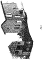
- the 3D point cloud may be rendered on a display in grayscale using the intensity values.
- FIG. 1 shows an exemplary rendering of a 3D point cloud in grayscale.
- the point cloud may be colorized using color information from color images acquired from cameras.
- FIG. 2 shows an exemplary color rendering of the same point cloud rendered in FIG. 1 .
- the color images are acquired by cameras that are either located inside or mounted on the scanning device.
- Conventional colorization approaches may make the following assumptions: (1) the cameras are fully calibrated, i.e., the intrinsic and extrinsic parameters are estimated beforehand, typically using a dedicated environment with specific targets; and/or (2) the camera locations are close to the scanner origin, so that the scan points can be colorized using a simple projection mechanism.
- FIG. 3 illustrates an example of such visual artifacts.
- the area 310 on a column and the area 320 on a wall are colorized with the color of a car located in front of the column and the wall.
- Embodiments of the present invention provide methods for colorizing a 3D point cloud acquired by a scanner using color photographs acquired by a camera that is not necessarily positioned close to the scanner origin and whose parameters are only known approximately.
- the camera is mounted inside the scanner with a significant parallax.
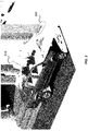
- FIGS. 4A-4C show an exemplary scanner 400 with a built-in camera 410 according to an embodiment of the present invention.
- the scanner 400 includes a 3D sensor 420 that is configured to emit a laser beam toward a scene and detect a return laser beam reflected by an object in the scene.
- the position of the camera 410 is relatively far away from the scanner origin (i.e., where the laser beam may be emitted from the 3D sensor 420).
- the camera 410 may be located at about 20 cm from the scan origin.
- only approximate camera parameters are needed for the colorization.
- the approximate camera parameters may be obtained from computer-aided design (CAD) data for the scanner 400 and the technical sheet of the camera 410 from the camera supplier.
- CAD computer-aided design
- One advantage of the colorization method disclosed herein is that the need for a camera calibration during production or servicing of the instrument may be eliminated.
- FIG. 5 shows a simplified flowchart illustrating a method 500 of colorizing a 3D point cloud according to an embodiment of the present invention.
- the method 500 includes, at 510, inputting a 3D point cloud acquired by a 3D sensor; at 520, inputting a set of color photographs acquired by a camera; and at 530, inputting approximate camera parameters.
- the 3D point cloud includes x, y, and z coordinates and intensity values for a set of points.
- the set of color photographs include images of the same environment as that of the 3D point cloud.
- the camera used for acquiring the photographs may be located relatively far from the 3D sensor used for acquiring the 3D point cloud.
- the approximate camera parameters may be obtained from CAD data for the scanner and the technical sheet of the camera.
- the method 500 further includes, at 540, performing camera auto-calibration using the 3D point cloud, the photographs, and the approximate camera parameters to obtain refined camera parameters.
- the camera auto-calibration is performed by matching the photographs with the 3D point cloud using only the approximate camera parameters.
- the method 500 further includes, at 550, colorizing the 3D point cloud using the refined camera parameters.
- colorizing the 3D point cloud is performed using occlusion detection to avoid colorizing the scan points that are not visible from the camera.
- the method may be applied for any camera position and orientation with respect to the 3D sensor.
- the method 500 further includes, at 560, outputting the colored 3D point cloud.
- the method 500 may be applied to the scanner 400 setup illustrated in FIGS. 4A-4C (e.g., the Trimble TX series scanners).
- the method 500 may also be applied to other instruments or setups.
- it may be applied to a handheld or mobile scanner, as well as a terrestrial scanner.
- the camera can be a built-in camera 410 that is permanently fixed in the scanner, as illustrated in FIGS. 4A-4C , or it can be a separate camera.
- FIGS. 6A and 6B show some other possible camera arrangements.
- the camera can be a conventional camera 610 mounted on the scanning device 600, as illustrated in FIG. 6A .
- the camera can also be a completely separate external camera.
- the camera 610 can be mounted on a drone, held by a person, or mounted on a separate tripod, as illustrated in FIG. 6B .
- the approximate extrinsic camera parameters may be obtained from sensors such as inertial measurement unit (IMU), global navigation satellite system (GNSS) (e.g., the Global Positioning System (GPS)), compass, pressure sensor (for elevation changes), and like.
- IMU inertial measurement unit
- GNSS global navigation satellite system
- GPS Global Positioning System
- the camera may be a thermal camera instead of a visible range camera.
- the camera can also be a panoramic camera in some embodiments.
- FIG. 7 illustrates schematically an exemplary (e.g., a Trimble TX series) setup according to an embodiment of the present invention.
- the scanner 400 may be similar to the scanner illustrated in FIG. 4 , which includes a built-in camera 410.
- the scanner 400 may acquire a point cloud.
- the built-in camera may take a set of color photographs 740a-740f of the same environment at several positions, for example at positions 1-6 in a 360-degree panorama.
- Camera auto-calibration may be performed in order to project 3D points into corresponding pixel locations in the photographs. Colorization of the 3D point clouds may then be performed by assigning colors in the photographs to the corresponding 3D points.
- the steps of camera auto-calibration and colorization will be described in more detail below.
- a set of camera parameters needs to be estimated.
- approximate intrinsic camera parameters such as focal length, optical center, principal point, and distortion parameters
- the approximate extrinsic camera parameters such as the camera position and orientation (e.g., the viewing direction in terms of up-down direction and left-right direction) may be used as a starting point.
- a set of refined camera parameters are then estimated based on a given 3D point cloud and a set of photographs of the same environment using the approximate camera parameters. This process may be referred herein as auto-calibration because it is similar to a camera calibration step but does not require a dedicated environment with specific targets to be scanned and photographed.
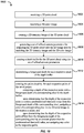
- FIG. 8 shows a simplified flowchart illustrating a method 800 of camera auto-calibration according to an embodiment of the present invention.
- the method 800 is based on image processing techniques.
- the input includes a 3D point cloud with intensity data (810), a set of photographs of the same environment taken by a camera (820), and a set of approximate camera parameters (830) (including intrinsic and extrinsic camera parameters).
- the processing steps include creating intensity images from the 3D point cloud using the approximate camera parameters (840), and performing image processing to match the intensity images with the photographs (850).
- the output is a set of refined camera parameters (860).
- the processing steps 840 and 850 are described in more detail below.
- the method 800 includes creating 2D intensity images from the 3D point cloud using the set of approximate camera parameters (840).
- the set of approximate camera parameters includes intrinsic and extrinsic parameters needed to define a camera projection.
- the intrinsic camera parameters may include the focal length of the camera lens in pixels or mm (in which case the pixel size in mm is needed), the optical center and the principal point of the camera lens, and the distortion model and associated parameters of the camera lens.
- the extrinsic camera parameters may include the position and orientation of the camera with respect to the scanner coordinate frame corresponding to the acquisition condition of each photograph.
- the output may include a set of refined camera parameters, which may be used to obtain accurate 2D projections of the 3D point cloud onto the pixels of each photograph.
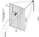
- the 3D point cloud may be projected onto a 2D intensity image having the same size as a corresponding photograph from the viewpoint of the camera position when the photograph is taken.
- FIG. 9 illustrates schematically the projection of a 3D point cloud onto a 2D intensity image 910 according to an embodiment of the present invention. Using the approximate camera parameters, each point of the 3D point cloud is projected onto a corresponding pixel in the 2D image 910. The intensity of the corresponding pixel in the 2D image 910 is the laser intensity of the respective 3D point. In cases where more than one 3D points are projected onto the same pixel, the intensity of the that pixel is the laser intensity of the point that is closest to the camera position.
- this is achieved by computing two images of equal size, one for the intensity and one for the depth.
- the depth image includes depth information of each point in the 3D point cloud with respect to the camera position.
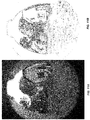
- FIG. 10A shows an exemplary intensity image in grey scale projected from a 3D point cloud according to an embodiment of the present invention.
- the method includes, at 850, performing image processing to obtain a set of refined camera parameters (860).
- the set of refined camera parameters may include 2D translation (T), 2D rotation (R), and 2D scaling (S) parameters for projecting the 3D point cloud accurately to a 2D image corresponding to a photograph.
- image matching may be performed by iterative matching of edges using a template matching algorithm.
- image processing may include, at 854, detecting a set of edges in a 2D intensity image, and at 856 detecting a set of edges in a corresponding photograph.
- Edges may be detected by computing the gradients and applying thresholding on the magnitudes of the gradients.
- the 2D intensity image may be cleaned up before edge detection (852).
- a smoothing operation may be performed on the 2D intensity image before computing the gradients.
- the edge detection algorithm may produce two images, which may be referred to as edge images.
- FIG. 10B shows an edge image created from the 2D intensity image shown in FIG. 10A according to an embodiment.
- FIG. 11A shows a photograph of the same scene.
- FIG. 11B shows an edge image created from the photograph shown in FIG. 11A according to an embodiment of the present invention.
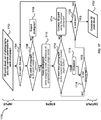
- FIG. 12 illustrates schematically an algorithm to estimate a best set of 2D translation, 2D rotation, and 2D scaling parameters that can match the edge image created from the 2D intensity image and the edge image created from the photograph according to an embodiment of the present invention.
- the algorithm may iteratively test every pair of 2D rotation and 2D scaling values, in a given range with a given step for each of the rotation and scaling. For each candidate pair of rotation and scaling values, the algorithm may find the best translation value using a template matching algorithm on the edge images, along with an associated score.
- the template matching algorithm uses Fourier transform, and the computed score is the cross-correlation score between the two images.
- the candidate pair of rotation and scaling values that gives the best score is kept. This may yield a set of final correction parameters for rotation, scaling, and translation that can be applied every time for converting the 3D coordinates of each point in the 3D point cloud to a corresponding pixel location on the image, or vice versa (provided that the relative position of the camera with respect to the 3D scanner is fixed). In this manner, a set of refined camera parameters, including the 2D translation, 2D rotation, and 2D scaling parameters, may be obtained without having to modify the approximate camera parameters themselves.
- N best solutions may be kept.
- Several photographs, e.g., M photographs, taken by the same camera may be used to obtain a total of N ⁇ M best solutions.
- M photographs taken by the same camera.
- multiple photographs may be taken by the same camera. Because there might be some issues in some images (e.g., due to moving objects, exposure issues, and the like), it may be more robust to estimate the refined camera parameters using all the images.
- FIG. 13 shows a simplified flowchart illustrating a method 1300 of estimating a set of refined camera parameters using multiple photographs according to an embodiment of the present invention.
- the input are a 3D point cloud, multiple photographs (e.g., M photographs), and approximate camera parameters for each photograph (1310).
- image matching may be performed to obtain N best solutions for the refined camera parameters (1350), using for example the method 800 as illustrated in FIG. 8 .
- the N best solution for each photograph are stored (1352).
- the method 1300 determines whether it is the last photograph (1360). If it is not the last photograph, the method 1300 proceeds to perform image matching for the next photograph to obtain another set of N best solutions, until image matching has been performed for all photographs.
- the process may produce a total of N ⁇ M best solutions for the set of refined camera parameters (1352).
- the method 1300 may then select a best solution among the N ⁇ M best solutions (1370).
- a clustering algorithm may be used to select a best solution among the N ⁇ M best solutions.
- the N ⁇ M best solutions may be plotted as data points in a parameter space.
- One or more clusters that include groups of data points with small distances among the cluster members may be identified.
- a solution among the most dense cluster may be selected as the final best solution.
- the selected best solution produces the final refined camera parameters (1380).
- a set of camera parameters may be directly estimated without estimating the 2D translation, 2D rotation, and 2D scaling parameters.
- an intensity image may be created from the 3D point cloud for each set of candidate camera parameters.
- An edge image may be computed for the 2D intensity image.
- a corresponding edge image may be computed for a corresponding photograph.
- the best set of camera parameters would be the ones that maximize a cross-correlation score between the two edge images.
- a set of features may be extracted from an intensity image and another set of features may be extracted from a corresponding color photograph.
- a set of refined camera parameters may be estimated by matching the two sets of features.
- a setup may include multiple cameras.
- a set of refined camera parameters may be estimated for each camera.
- the 3D point cloud may be accurately projected onto a 2D image area having the same size as a corresponding photograph.
- the 3D point cloud may then be colorized by assigning the colors in the paragraph to the corresponding points in the 3D point cloud. In other words, the color of each pixel in the photograph may be assigned to the 3D points projected to the same pixel.
- FIG. 14 illustrates schematically how this situation may arise in an exemplary setup.
- the setup includes a scanner 1400 with a built-in camera 1410 that is positioned at certain distance below the scanner origin 1420.
- the scene includes a house 1470 and a post 1460 located in front of the house 1470.
- the solid line 1422 indicates a line of sight from the scanner origin 1420 to the area 1472 on the house 1470.
- the dashed line 1412 indicates a line of sight from the camera 1410 to the same area 1472 on the house 1470.
- the area 1472 is visible to both the scanner 1400 and the camera 1410 simultaneously.
- the area 1472 in the 3D point cloud may be assigned the color at a corresponding pixel location in a photograph taken by the camera 1410.
- the area 1464 at the bottom of the post 1460 is visible to both the scanner 1400 and the camera 1410 simultaneously, and therefore the area 1464 in the 3D point cloud may be assigned the color at a corresponding pixel location in a photograph taken by the camera 1410.
- Areas such as the areas 1472 and 1464 may be referred herein as "normal" areas.
- the area 1474 on the house 1470 is visible to the scanner 1400 but not visible to the camera 1410, because the view of that area is obstructed from the camera 1410 by the post 1460 in the front. Therefore, the points in the point cloud corresponding to the area 1474 should not be assigned the colors at the corresponding pixel locations in the photograph, because doing so may resulting in assigning the colors of the post 1460 to those points representing the wall of the house 1470.
- Areas such as the area 1474 may be referred herein as "occluded" areas. Colorizing the occluded areas may result in visual artifact by assigning the color of the foreground object to the occluded area in the background.
- the area 1476 on the house 1470 is visible to neither the scanner 1400 nor the camera 1410, because it's view is obstructed from both the scanner 1400 and the camera 1410 by the post 1460. Areas like the area 1476 maybe referred herein as "empty" areas.
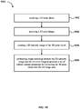
- FIG. 15 shows a simplified flowchart illustrating a method 1500 of occlusion detection according to an embodiment of the present invention.
- the input includes a 3D point cloud (1510), a set of photographs of the same environment (1520), and a set of refined camera parameters for each photograph (1530).
- the refined camera parameters may be obtained by the method 800 discussed above in relation to FIG. 8 .
- the processing steps may include: creating a depth buffer and detecting foreground depths for each photograph (1540); filtering points by visibility (1550) (e.g., filtering out background points); and coloring the foreground points (1560).
- the steps of depth buffer creation and foreground depths detection (1540), and points filtering by visibility (1550) are described in more detail below.
- a depth buffer may be created for the 3D point cloud.
- the depth buffer may have a pixel size that is the same as that of the photograph.
- the 3D point cloud may be projected onto the depth buffer from the viewpoint of the camera when the photograph is taken using the set of the refined camera parameters for the photograph.
- a foreground depth value i.e., the depth of the closest point among those points that are projected onto this specific pixel, may be detected and stored.
- FIG. 16 illustrates schematically how the foreground depths may be detected according to an embodiment of the present invention.
- the group of points 1634 are projected onto the pixels 1622 of the depth buffer 1620. Since these points are closest to the camera 1610 among the points that are projected onto the pixels 1622, their depths represent the foreground depths for the pixels 1622.
- the group of points 1636, as well as the group of points 1632, are projected onto the pixels 1624 of the depth buffer 1620. Because the group of points 1632 are closest to the camera 1610 among the points that are projected onto the pixels 1624, their depths represent the foreground depths for the pixels 1624.
- point filtering may be performed to remove background points from the depth buffer, i.e., to remove those points that are occluded from view by the foreground points and thus are not visible to the camera. The remaining points are then colored using the colors in the photograph.
- Occlusion detection may be performed by, for each point in the 3D point cloud, comparing its depth to the foreground depth value for the corresponding pixel.
- a threshold value may be used in the occlusion detection. For example, the method may determine a difference between the depth of the respective point and the foreground depth of the corresponding pixel. If the difference is greater than a predetermined threshold value, it may be determined that the respect point is occluded. Accordingly, the respective point may be removed from the depth buffer. Conversely, if the difference is less than the predetermined threshold value, it may be determined that the respect point is in the foreground. Accordingly, the respective point is kept.
- the threshold value may be dependent on the distance from the camera position.
- the group of points 1636 are occluded. Thus, those points are removed.
- the group of points 1634 and the group of points 1632 are in the foreground. Thus, those points are kept, and are colored using the colors of the photograph.
- image processing techniques such as mathematical morphology algorithms, may be applied to the depth buffer to filter out the background points. For example, closing operations of the mathematical morphology methodology may be performed on the depth buffer to remove background points. Isolated points may also be removed from the depth buffer.
- the method may handle a whole set of photographs in one process, referred herein as "full workflow,” according to some embodiments.
- FIG. 17 shows a simplified flowchart illustrating a method 1700 of colorizing a 3D point cloud using multiple photographs according to an embodiment of the present invention.
- the input includes a 3D point cloud, a set of photographs, and a set of refined camera parameters for each photograph (1702).
- the set of refined camera parameters may be obtained by the method 800 discussed above in relation to FIG. 8 .
- the method 1700 includes, for each 3D point (1704), for each respective photograph, determining whether the 3D point is visible to the camera as the respective photograph is taken (1706). If it is determined that the 3D point is not visible to the camera, the respective photograph is rejected (1708). If it is determined that the 3D point is visible to the camera, the respective photograph is kept (1710). If more than one photograph is kept, the photographs may be stored by the order of distances from the 3D point to the camera.
- the depth of the 3D point is greater than the depth of the corresponding pixel in the current depth buffer (1712).
- a threshold value may be used as described above. If it is determined that the depth of the 3D point is not greater than the depth of the corresponding pixel in the current depth buffer, the 3D point is colorized using the color of the corresponding pixel in the respective photograph (1714). It is then determined whether the 3D point is the last point (1720). If it is determined that it is not the last point, the method proceeds to a next 3D point. If it is determined that the 3D point is the last point, a colorized 3D point cloud is output (1722).
- the 3D point is not colorized (i.e., occluded) (1716). It is then determined whether it is the last kept photograph (1718). If it is determined that it is the last kept photograph, the method proceeds to determine if it is the last point (1720). If it is determined that is not the last photograph, the method proceeds to the next kept photograph until all kept photographs have been processed.
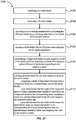
- FIG. 18 shows a simplified flowchart illustrating a method 1800 of colorizing a 3D point cloud according to an embodiment of the present invention.
- the method 1800 includes, at 1802, receiving the 3D point cloud.
- the 3D point cloud can be acquired by a 3D imaging device positioned at a first location.
- the 3D point cloud can include 3D coordinates and intensity data for a set of points representing surfaces of one or more objects.
- the method 1800 further includes, at 1804, receiving a 2D color image of the one or more objects acquired by a camera positioned at an approximately known second location and an approximately known orientation.
- the camera has an approximately known set of intrinsic optical parameter.
- the method 1800 further includes, at 1806, creating a 2D intensity image of the 3D point cloud using the intensity data by projecting the 3D point cloud onto a 2D image area from a view point of the second location based on the set of intrinsic optical parameters, the second location, and the orientation of the camera.
- the 2D image area can have a size that is the same as the size of the 2D color image.
- the method 1800 further includes, at 1808, generating a set of refined camera parameters for projecting the 3D point cloud onto the 2D image area by matching the 2D intensity image and the 2D color image.
- the method 1800 further includes, at 1810, creating a depth buffer for the 3D point cloud.
- the depth buffer can have an image area of a size that is the same as the size of the 2D color image and a pixel size that is the same as the pixel size of the 2D color image.
- the depth buffer includes depth data for the set of points in the 3D point cloud as the set of points are projected onto pixels of the depth buffer using the set of refined camera parameters.
- the method 1800 further includes, at 1812, determining a foreground depth for each respective pixel of the depth buffer by detecting a closest point among a subset of the set of points corresponding to the respective pixel.
- the method 1800 further includes, at 1814, coloring the point cloud by, for each respective point of the set of points: comparing a depth of the respective point with a foreground depth of a corresponding pixel in the depth buffer; upon determining that the depth of the respective point is within a predetermined threshold value from the foreground depth of the corresponding pixel, assigning a color of a corresponding pixel in the 2D color image to the respective point; and upon determining that the depth of the respective point differs from the foreground depth of the corresponding pixel by an amount greater than the predetermined threshold value, not assigning any color to the respective point.
- FIG. 19 shows a simplified flowchart illustrating a method 1900 of camera calibration with respect to a 3D imaging device according to an embodiment of the present invention.
- the method 1900 includes, at 1902, receiving a 3D point cloud acquired by the 3D imaging device positioned at a first location.
- the 3D point cloud can include 3D coordinates and intensity data for a set of points representing surfaces of one or more objects.
- the method 1900 further includes, at 1904, receiving a 2D color image of the one or more objects acquired by a camera positioned at an approximately known second location and an approximately known orientation.
- the camera can have an approximately known set of intrinsic optical parameters.
- the method 1900 further includes, at 1906, creating a 2D intensity image of the 3D point cloud using the intensity data by projecting the 3D point cloud onto a 2D image area from a view point of the second location based on the set of intrinsic optical parameters of the camera, the second location, and the orientation of the camera.
- the 2D image area can have a size that is the same as the size of the 2D color image.
- the method 1900 further includes, at 1908, performing image matching between the 2D intensity image and the 2D color image to generate a set of refined camera parameters for projecting the 3D point cloud onto the 2D image area.
- FIG. 20 shows a simplified flowchart illustrating a method 2000 of camera calibration with respect to a 3D imaging device according to another embodiment of the present invention.
- the method 2000 includes, at 2002, receiving a 3D point cloud acquired by the 3D imaging device.
- the 3D point cloud can include 3D coordinates and intensity data for a set of points representing surfaces of one or more objects.
- the method 2000 further includes, at 2004, receiving a plurality of two-dimensional (2D) color images of the one or more objects acquired by a camera positioned at a plurality of corresponding locations and a plurality of corresponding orientations.
- the camera can have an approximately known set of intrinsic optical parameters.
- the method 2000 further includes, at 2006, generating a plurality of sets of refined camera parameters by, for each respective 2D color image of the plurality of 2D color images: creating a respective 2D intensity image of the 3D point cloud using the intensity data by projecting the 3D point cloud onto a 2D image area from a view point of the camera based on a respective location and respective orientation, and the set of intrinsic optical parameters of the camera, the 2D image area having a size that is the same as the size of the 2D color image; and performing image matching between the respective 2D intensity image and the respective 2D color image to generate a respective set of refined camera parameters for projecting the 3D point cloud onto the 2D image area.
- the method 2000 further includes, at 2008, selecting one set of the refined camera parameters from the plurality of sets of refined camera parameters as a final set of refined camera parameters.
- selecting the one set of the refined camera parameters is performed using a clustering algorithm, as described above.
- FIG. 21 shows a simplified flowchart illustrating a method 2100 of colorizing a 3D point cloud according to an embodiment of the present invention.
- the method 2100 includes, at 2102, receiving the 3D point cloud.
- the 3D point cloud can be acquired by a 3D imaging device positioned at a first location.
- the 3D point cloud can include 3D coordinates for a set of points representing surfaces of one or more objects.
- the method 2100 further includes, at 2104, receiving a 2D color image of the one or more objects acquired by a camera positioned at a second location different from the first location and having an orientation.
- the method 2100 further includes, at 2106, receiving a set of camera parameters for projecting the 3D point cloud onto a 2D image area from a view point of the second location.
- the 2D image area can have a size that is the same as the size of the 2D color image.
- the method 1700 further includes, at 2108, creating a depth buffer for the 3D point cloud.
- the depth buffer can have an image area of a size that is the same as the size of the 2D color image and a pixel size that is the same as the pixel size of the 2D color image.
- the depth buffer can include depth data for the set of points in the 3D point cloud as the set of points are projected onto pixels of the depth buffer using the set of camera parameters.
- the method 2100 further includes, at 2110, determining a foreground depth for each respective pixel of the depth buffer by detecting a closest point among a subset of the set of points corresponding to the respective pixel.
- the method 2100 further includes, at 2112, coloring the point cloud by, for each respective point of the set of points: comparing a depth of the respective point with a foreground depth of a corresponding pixel in the depth buffer; upon determining that the depth of the respective point is within a predetermined threshold value from the foreground depth of the corresponding pixel, assigning a color of a corresponding pixel in the 2D color image to the respective point; and upon determining that the depth of the respective point differs from the foreground depth of the corresponding pixel by an amount greater than the predetermined threshold value, not assigning any color to the respective point.
- FIGS. 5 , 8 , 13 , 15 , and 17-21 provide particular methods according to various embodiments of the present invention. Other sequences of steps may also be performed according to alternative embodiments. For example, alternative embodiments of the present invention may perform the steps outlined above in a different order. Moreover, the individual steps illustrated in each of FIGS. 5 , 8 , 13 , 15 , and 17-20 may include multiple sub-steps that may be performed in various sequences as appropriate to the individual step. Furthermore, additional steps may be added or removed depending on the particular applications.
Applications Claiming Priority (1)
| Application Number | Priority Date | Filing Date | Title |
|---|---|---|---|
| US15/451,834 US10237532B2 (en) | 2017-03-07 | 2017-03-07 | Scan colorization with an uncalibrated camera |
Publications (1)
| Publication Number | Publication Date |
|---|---|
| EP3373251A1 true EP3373251A1 (de) | 2018-09-12 |
Family
ID=62143070
Family Applications (1)
| Application Number | Title | Priority Date | Filing Date |
|---|---|---|---|
| EP18305240.6A Pending EP3373251A1 (de) | 2017-03-07 | 2018-03-07 | Scan-kolorierung mit einer unkalibrierten kamera |
Country Status (2)
| Country | Link |
|---|---|
| US (1) | US10237532B2 (de) |
| EP (1) | EP3373251A1 (de) |
Cited By (3)
| Publication number | Priority date | Publication date | Assignee | Title |
|---|---|---|---|---|
| US10237532B2 (en) | 2017-03-07 | 2019-03-19 | Trimble Ab | Scan colorization with an uncalibrated camera |
| CN113362276A (zh) * | 2021-04-26 | 2021-09-07 | 广东大自然家居科技研究有限公司 | 板材视觉检测方法及系统 |
| EP4224430A1 (de) * | 2022-02-02 | 2023-08-09 | Faro Technologies, Inc. | Scan-farbwiederherstellung |
Families Citing this family (13)
| Publication number | Priority date | Publication date | Assignee | Title |
|---|---|---|---|---|
| EP3349182A1 (de) * | 2017-01-13 | 2018-07-18 | Thomson Licensing | Verfahren, vorrichtung und stream für immersives videoformat |
| EP3351899B1 (de) * | 2017-01-24 | 2020-06-17 | Leica Geosystems AG | Verfahren und vorrichtung zum "colorising" von dreidimensionalen punktwolken |
| US10410406B2 (en) | 2017-02-27 | 2019-09-10 | Trimble Ab | Enhanced three-dimensional point cloud rendering |
| CN110476037B (zh) * | 2017-04-03 | 2022-01-11 | 富士通株式会社 | 距离信息处理装置、距离信息处理方法以及距离信息处理程序 |
| JP7250493B2 (ja) * | 2018-12-03 | 2023-04-03 | キヤノン株式会社 | 画像処理装置、三次元形状データの生成方法およびプログラム |
| US10937202B2 (en) * | 2019-07-22 | 2021-03-02 | Scale AI, Inc. | Intensity data visualization |
| CN111047650B (zh) * | 2019-12-02 | 2023-09-01 | 北京深测科技有限公司 | 一种用于飞行时间相机的参数标定方法 |
| US11861857B2 (en) * | 2020-12-08 | 2024-01-02 | Zoox, Inc. | Determining pixels beyond nominal maximum sensor depth |
| US11954877B2 (en) | 2020-12-08 | 2024-04-09 | Zoox, Inc. | Depth dependent pixel filtering |
| US20220351394A1 (en) * | 2021-04-27 | 2022-11-03 | Faro Technologies, Inc. | Hybrid feature matching between intensity image and color image |
| US20220351417A1 (en) * | 2021-04-27 | 2022-11-03 | Faro Technologies, Inc. | Occlusion detection for laser scan-point coloring |
| US11790557B2 (en) * | 2021-04-27 | 2023-10-17 | Faro Technologies, Inc. | Calibrating system for colorizing point-clouds |
| US20230209035A1 (en) * | 2021-12-28 | 2023-06-29 | Faro Technologies, Inc. | Artificial panorama image production and in-painting for occluded areas in images |
Citations (3)
| Publication number | Priority date | Publication date | Assignee | Title |
|---|---|---|---|---|
| US20110115812A1 (en) * | 2009-11-13 | 2011-05-19 | Harris Corporation | Method for colorization of point cloud data based on radiometric imagery |
| US20150341552A1 (en) * | 2014-05-21 | 2015-11-26 | Here Global B.V. | Developing a Panoramic Image |
| WO2016019576A1 (en) * | 2014-08-08 | 2016-02-11 | Carestream Health, Inc. | Facial texture mapping to volume image |
Family Cites Families (27)
| Publication number | Priority date | Publication date | Assignee | Title |
|---|---|---|---|---|
| US8253729B1 (en) | 1983-05-09 | 2012-08-28 | Geshwind David M | Trimming depth buffer during 2D to 3D conversion |
| US4967392A (en) | 1988-07-27 | 1990-10-30 | Alliant Computer Systems Corporation | Drawing processor for computer graphic system using a plurality of parallel processors which each handle a group of display screen scanlines |
| US6377265B1 (en) | 1999-02-12 | 2002-04-23 | Creative Technology, Ltd. | Digital differential analyzer |
| US6674894B1 (en) | 1999-04-20 | 2004-01-06 | University Of Utah Research Foundation | Method and apparatus for enhancing an image using data optimization and segmentation |
| US7154515B2 (en) | 2001-06-15 | 2006-12-26 | Perkinelmer, Inc. | Method and apparatus for reducing printing artifacts of stitched images |
| DE112005003695B4 (de) | 2005-09-29 | 2012-07-26 | Intel Corp. | Fehlerverteilung zum Stromsparen bei Anzeige-Bildspeichern |
| US8542252B2 (en) | 2009-05-29 | 2013-09-24 | Microsoft Corporation | Target digitization, extraction, and tracking |
| US20110025689A1 (en) | 2009-07-29 | 2011-02-03 | Microsoft Corporation | Auto-Generating A Visual Representation |
| WO2011106379A1 (en) | 2010-02-23 | 2011-09-01 | Astronautics Corporation Of America | Single processor class-3 electronic flight bag |
| FI20106300A0 (fi) | 2010-12-08 | 2010-12-08 | Juuso Siren | Menetelmä, järjestelmä ja tietokoneohjelmatuote point cloudin visualisointiin |
| US9208571B2 (en) | 2011-06-06 | 2015-12-08 | Microsoft Technology Licensing, Llc | Object digitization |
| US9525862B2 (en) * | 2011-08-31 | 2016-12-20 | Metaio Gmbh | Method for estimating a camera motion and for determining a three-dimensional model of a real environment |
| WO2013128264A2 (en) | 2012-03-01 | 2013-09-06 | Trimble A.B. | Methods and apparatus for point cloud data management |
| US20130265305A1 (en) | 2012-04-04 | 2013-10-10 | Jon N. Hasselgren | Compressed Depth Cache |
| US9142022B2 (en) | 2013-10-11 | 2015-09-22 | Intel Corporation | 3D object tracking |
| EP3066553B1 (de) | 2013-11-08 | 2020-02-12 | Fujitsu Limited | Speichervorrichtung und verfahren dafür zur inline-deduplizierung mit segmentierung |
| US10311633B2 (en) | 2014-01-17 | 2019-06-04 | Nokia Technologies Oy | Method and apparatus for visualization of geo-located media contents in 3D rendering applications |
| US9996976B2 (en) | 2014-05-05 | 2018-06-12 | Avigilon Fortress Corporation | System and method for real-time overlay of map features onto a video feed |
| US9693040B2 (en) * | 2014-09-10 | 2017-06-27 | Faro Technologies, Inc. | Method for optically measuring three-dimensional coordinates and calibration of a three-dimensional measuring device |
| US10417817B2 (en) | 2014-11-13 | 2019-09-17 | Nvidia Corporation | Supersampling for spatially distributed and disjoined large-scale data |
| CN106663411A (zh) | 2014-11-16 | 2017-05-10 | 易欧耐特感知公司 | 用于增强现实准备、处理和应用的系统和方法 |
| US9286680B1 (en) * | 2014-12-23 | 2016-03-15 | Futurewei Technologies, Inc. | Computational multi-camera adjustment for smooth view switching and zooming |
| US9959643B2 (en) | 2015-10-29 | 2018-05-01 | Intel Corporation | Variable rasterization order for motion blur and depth of field |
| US10121222B2 (en) | 2016-01-22 | 2018-11-06 | Mediatek Inc. | Bandwidth efficient method for generating an alpha hint buffer |
| US10066925B2 (en) * | 2016-02-02 | 2018-09-04 | The Boeing Company | Point cloud processing apparatus and method |
| US10410406B2 (en) | 2017-02-27 | 2019-09-10 | Trimble Ab | Enhanced three-dimensional point cloud rendering |
| US10237532B2 (en) | 2017-03-07 | 2019-03-19 | Trimble Ab | Scan colorization with an uncalibrated camera |
-
2017
- 2017-03-07 US US15/451,834 patent/US10237532B2/en active Active
-
2018
- 2018-03-07 EP EP18305240.6A patent/EP3373251A1/de active Pending
Patent Citations (3)
| Publication number | Priority date | Publication date | Assignee | Title |
|---|---|---|---|---|
| US20110115812A1 (en) * | 2009-11-13 | 2011-05-19 | Harris Corporation | Method for colorization of point cloud data based on radiometric imagery |
| US20150341552A1 (en) * | 2014-05-21 | 2015-11-26 | Here Global B.V. | Developing a Panoramic Image |
| WO2016019576A1 (en) * | 2014-08-08 | 2016-02-11 | Carestream Health, Inc. | Facial texture mapping to volume image |
Non-Patent Citations (1)
| Title |
|---|
| D. DAHLKE ET AL: "COMPARISON BETWEEN TWO GENERIC 3D BUILDING RECONSTRUCTION APPROACHES - POINT CLOUD BASED VS. IMAGE PROCESSING BASED", ISPRS - INTERNATIONAL ARCHIVES OF THE PHOTOGRAMMETRY, REMOTE SENSING AND SPATIAL INFORMATION SCIENCES, vol. XLI-B3, 9 June 2016 (2016-06-09), pages 599 - 604, XP055486648, DOI: 10.5194/isprsarchives-XLI-B3-599-2016 * |
Cited By (3)
| Publication number | Priority date | Publication date | Assignee | Title |
|---|---|---|---|---|
| US10237532B2 (en) | 2017-03-07 | 2019-03-19 | Trimble Ab | Scan colorization with an uncalibrated camera |
| CN113362276A (zh) * | 2021-04-26 | 2021-09-07 | 广东大自然家居科技研究有限公司 | 板材视觉检测方法及系统 |
| EP4224430A1 (de) * | 2022-02-02 | 2023-08-09 | Faro Technologies, Inc. | Scan-farbwiederherstellung |
Also Published As
| Publication number | Publication date |
|---|---|
| US20180262737A1 (en) | 2018-09-13 |
| US10237532B2 (en) | 2019-03-19 |
Similar Documents
| Publication | Publication Date | Title |
|---|---|---|
| US10237532B2 (en) | Scan colorization with an uncalibrated camera | |
| US10636151B2 (en) | Method for estimating the speed of movement of a camera | |
| JP5580164B2 (ja) | 光学情報処理装置、光学情報処理方法、光学情報処理システム、光学情報処理プログラム | |
| CN103959012B (zh) | 6自由度位置和取向确定 | |
| US9772405B2 (en) | Backfilling clouds of 3D coordinates | |
| CN107025663B (zh) | 视觉系统中用于3d点云匹配的杂波评分系统及方法 | |
| EP2111530B1 (de) | Automatische stereomessung eines punkts von interesse in einer szene | |
| JP5132832B1 (ja) | 計測装置および情報処理装置 | |
| US20120242795A1 (en) | Digital 3d camera using periodic illumination | |
| JP7300948B2 (ja) | 測量データ処理装置、測量データ処理方法、測量データ処理用プログラム | |
| EP1580523A1 (de) | Verfahren zur dreidimensionalen formmessung und einrichtungdafür | |
| WO2018227576A1 (zh) | 地面形态检测方法及系统、无人机降落方法和无人机 | |
| US20090196491A1 (en) | Method for automated 3d imaging | |
| JP5633058B1 (ja) | 3次元計測装置及び3次元計測方法 | |
| US11082633B2 (en) | Method of estimating the speed of displacement of a camera | |
| KR20120058828A (ko) | 3차원 좌표 추출 시스템 및 그 방법 | |
| KR20110059631A (ko) | 3차원 계측 장치 및 그 방법 | |
| EP3382645A2 (de) | Verfahren zur erzeugung eines 3d-modells auf basis von structure from motion und photometrischem stereo von sparse 2d bildern | |
| US11803982B2 (en) | Image processing device and three-dimensional measuring system | |
| JP2013069235A (ja) | 対象物複数画像対応付け装置、そのデータ再生装置、画像処理システム | |
| CN112816967A (zh) | 图像距离测量方法、装置、测距设备和可读存储介质 | |
| JP2017517727A (ja) | 三次元情報の規模測定 | |
| JP4379626B2 (ja) | 3次元形状計測方法及びその装置 | |
| EP2826243B1 (de) | Verfahren und system zur identifizierung von tiefendaten in verbindung mit einem objekt | |
| JP2013160602A (ja) | 写真測量装置 |
Legal Events
| Date | Code | Title | Description |
|---|---|---|---|
| PUAI | Public reference made under article 153(3) epc to a published international application that has entered the european phase |
Free format text: ORIGINAL CODE: 0009012 |
|
| STAA | Information on the status of an ep patent application or granted ep patent |
Free format text: STATUS: THE APPLICATION HAS BEEN PUBLISHED |
|
| AK | Designated contracting states |
Kind code of ref document: A1 Designated state(s): AL AT BE BG CH CY CZ DE DK EE ES FI FR GB GR HR HU IE IS IT LI LT LU LV MC MK MT NL NO PL PT RO RS SE SI SK SM TR |
|
| AX | Request for extension of the european patent |
Extension state: BA ME |
|
| STAA | Information on the status of an ep patent application or granted ep patent |
Free format text: STATUS: REQUEST FOR EXAMINATION WAS MADE |
|
| 17P | Request for examination filed |
Effective date: 20180925 |
|
| RBV | Designated contracting states (corrected) |
Designated state(s): AL AT BE BG CH CY CZ DE DK EE ES FI FR GB GR HR HU IE IS IT LI LT LU LV MC MK MT NL NO PL PT RO RS SE SI SK SM TR |
|
| STAA | Information on the status of an ep patent application or granted ep patent |
Free format text: STATUS: EXAMINATION IS IN PROGRESS |
|
| 17Q | First examination report despatched |
Effective date: 20210301 |
|
| STAA | Information on the status of an ep patent application or granted ep patent |
Free format text: STATUS: EXAMINATION IS IN PROGRESS |