EP3373244A2 - Automatic eardrum registration from light field data - Google Patents
Automatic eardrum registration from light field data Download PDFInfo
- Publication number
- EP3373244A2 EP3373244A2 EP18159173.6A EP18159173A EP3373244A2 EP 3373244 A2 EP3373244 A2 EP 3373244A2 EP 18159173 A EP18159173 A EP 18159173A EP 3373244 A2 EP3373244 A2 EP 3373244A2
- Authority
- EP
- European Patent Office
- Prior art keywords
- eardrum
- dimensional image
- center
- location
- determining
- Prior art date
- Legal status (The legal status is an assumption and is not a legal conclusion. Google has not performed a legal analysis and makes no representation as to the accuracy of the status listed.)
- Withdrawn
Links
Images




Classifications
-
- A—HUMAN NECESSITIES
- A61—MEDICAL OR VETERINARY SCIENCE; HYGIENE
- A61B—DIAGNOSIS; SURGERY; IDENTIFICATION
- A61B1/00—Instruments for performing medical examinations of the interior of cavities or tubes of the body by visual or photographical inspection, e.g. endoscopes; Illuminating arrangements therefor
- A61B1/00002—Operational features of endoscopes
- A61B1/00004—Operational features of endoscopes characterised by electronic signal processing
- A61B1/00009—Operational features of endoscopes characterised by electronic signal processing of image signals during a use of endoscope
- A61B1/000094—Operational features of endoscopes characterised by electronic signal processing of image signals during a use of endoscope extracting biological structures
-
- A—HUMAN NECESSITIES
- A61—MEDICAL OR VETERINARY SCIENCE; HYGIENE
- A61B—DIAGNOSIS; SURGERY; IDENTIFICATION
- A61B1/00—Instruments for performing medical examinations of the interior of cavities or tubes of the body by visual or photographical inspection, e.g. endoscopes; Illuminating arrangements therefor
- A61B1/227—Instruments for performing medical examinations of the interior of cavities or tubes of the body by visual or photographical inspection, e.g. endoscopes; Illuminating arrangements therefor for ears, i.e. otoscopes
-
- G—PHYSICS
- G06—COMPUTING OR CALCULATING; COUNTING
- G06F—ELECTRIC DIGITAL DATA PROCESSING
- G06F18/00—Pattern recognition
- G06F18/20—Analysing
- G06F18/23—Clustering techniques
- G06F18/232—Non-hierarchical techniques
- G06F18/2323—Non-hierarchical techniques based on graph theory, e.g. minimum spanning trees [MST] or graph cuts
-
- G—PHYSICS
- G06—COMPUTING OR CALCULATING; COUNTING
- G06T—IMAGE DATA PROCESSING OR GENERATION, IN GENERAL
- G06T3/00—Geometric image transformations in the plane of the image
- G06T3/40—Scaling of whole images or parts thereof, e.g. expanding or contracting
-
- G—PHYSICS
- G06—COMPUTING OR CALCULATING; COUNTING
- G06T—IMAGE DATA PROCESSING OR GENERATION, IN GENERAL
- G06T7/00—Image analysis
- G06T7/0002—Inspection of images, e.g. flaw detection
- G06T7/0012—Biomedical image inspection
- G06T7/0014—Biomedical image inspection using an image reference approach
-
- G—PHYSICS
- G06—COMPUTING OR CALCULATING; COUNTING
- G06T—IMAGE DATA PROCESSING OR GENERATION, IN GENERAL
- G06T7/00—Image analysis
- G06T7/30—Determination of transform parameters for the alignment of images, i.e. image registration
- G06T7/33—Determination of transform parameters for the alignment of images, i.e. image registration using feature-based methods
-
- G—PHYSICS
- G06—COMPUTING OR CALCULATING; COUNTING
- G06T—IMAGE DATA PROCESSING OR GENERATION, IN GENERAL
- G06T7/00—Image analysis
- G06T7/30—Determination of transform parameters for the alignment of images, i.e. image registration
- G06T7/33—Determination of transform parameters for the alignment of images, i.e. image registration using feature-based methods
- G06T7/344—Determination of transform parameters for the alignment of images, i.e. image registration using feature-based methods involving models
-
- G—PHYSICS
- G06—COMPUTING OR CALCULATING; COUNTING
- G06V—IMAGE OR VIDEO RECOGNITION OR UNDERSTANDING
- G06V20/00—Scenes; Scene-specific elements
- G06V20/60—Type of objects
- G06V20/64—Three-dimensional [3D] objects
-
- G—PHYSICS
- G06—COMPUTING OR CALCULATING; COUNTING
- G06T—IMAGE DATA PROCESSING OR GENERATION, IN GENERAL
- G06T2207/00—Indexing scheme for image analysis or image enhancement
- G06T2207/10—Image acquisition modality
- G06T2207/10028—Range image; Depth image; 3D point clouds
-
- G—PHYSICS
- G06—COMPUTING OR CALCULATING; COUNTING
- G06T—IMAGE DATA PROCESSING OR GENERATION, IN GENERAL
- G06T2207/00—Indexing scheme for image analysis or image enhancement
- G06T2207/10—Image acquisition modality
- G06T2207/10052—Images from lightfield camera
-
- G—PHYSICS
- G06—COMPUTING OR CALCULATING; COUNTING
- G06T—IMAGE DATA PROCESSING OR GENERATION, IN GENERAL
- G06T2207/00—Indexing scheme for image analysis or image enhancement
- G06T2207/30—Subject of image; Context of image processing
- G06T2207/30004—Biomedical image processing
-
- G—PHYSICS
- G06—COMPUTING OR CALCULATING; COUNTING
- G06V—IMAGE OR VIDEO RECOGNITION OR UNDERSTANDING
- G06V2201/00—Indexing scheme relating to image or video recognition or understanding
- G06V2201/03—Recognition of patterns in medical or anatomical images
- G06V2201/031—Recognition of patterns in medical or anatomical images of internal organs
Definitions
- This disclosure relates generally to analysis of light field images and three-dimensional images of the eardrum.
- the plenoptic otoscope or light field otoscope is a type of medical otoscope that enables non-invasive three-dimensional (3D) imaging of the middle ear. Unlike traditional digital otoscopes that capture two-dimensional (2D) images, the LFO captures four-dimensional (4D) light field data from which 3D information can be recovered using digital processing techniques.
- the 3D shape of the eardrum is one of the most important factors for distinguishing Acute Otitis Media (AOM) which is a bacterial infection of the middle ear and requires antimicrobial treatment, from Otitis Media with Effusion (OME) which is a sterile effusion and tends to resolve on its own, and from No Effusion (NOE) which is a normal eardrum condition. Therefore, the 3D reconstruction of the eardrum (also called the tympanic membrane or TM) obtained using the LFO, has significant potential for automated diagnosis of otitis media.
- AOM Acute Otitis Media
- OME Otitis Media with Effusion
- NOE No Effusion
- a three-dimensional image (e.g., depth map) of an eardrum is produced from four-dimensional light field data captured by a light field otoscope.
- the three-dimensional image is registered as defined by a predefined standard form.
- the eardrum is then classified based on the registered three-dimensional image. Registration may include compensation for out-of-plane rotation (tilt), for in-plane rotation, for center location, for translation, and/or for scaling.
- Figure 1 contains example images of the TM taken in the field.
- the TM can be positioned, rotated and scaled differently, due to differences in how the LFO device was held during image acquisition and differences in TMs of different people.
- the tilt of the TM within the ear canal can also be different.
- the TM exhibits out-of-plane rotation within each image.
- these image-to-image variations are removed or at least reduced, so that a standardized image can be presented for automatic classification.
- a registration process that removes variations in translation/position, in- and out-of-plane rotation and scale will help to make the automatic classification invariant to these quantities.
- FIG. 2a is a flow diagram for automatic eardrum classification using an LFO, according to various embodiments.
- a LFO captures 210 a plenoptic image containing 4D light field data of the middle ear, including the eardrum.
- the 4D light field data is processed 220 to produce a 3D image of the eardrum.
- this 3D image may have variations in tilt, position and scale as described above.
- the 3D image of the eardrum is registered as defined by a predefined standard form, as will be described in greater detail below.
- the registered 3D image is used to classify 240 the eardrum, for example as AOM, OME or NOE.
- Figure 2b is a diagram of a LFO suitable for use in capturing 210 a 4D light field image of the eardrum.
- Figure 2c is a diagram of an example optical train for the LFO of Figure 2b .
- the otoscope 250 is handheld and includes a main body and a handle.
- the main body houses the optics 260 and the plenoptic sensor 270.
- the handle includes illumination 252 for the otoscope 250.
- the optics 260 includes an otoscope objective 262 and relay optics 264a-b.
- the plenoptic sensor 270 is a sensor array 274 with a microimaging array 272 (e.g., a microlens array or pinhole array) mounted in front of it.
- a microimaging array 272 e.g., a microlens array or pinhole array
- a disposable speculum 255 is attachable to the tip of the otoscope.
- the output of the plenoptic sensor 270 is transmitted to a separate computer system 280, which processes the captured light field data and displays the desired results.
- the computer system 280 may implement the automatic classification process described in Figure 2 .
- the imaging optics 260 form a conventional image within the otoscope instrument at an intermediate image plane 12.
- a plenoptic sensor 270 captures the image.
- the microlens array 272 is positioned at the intermediate image plane I2 and a sensor array 274 is positioned at a conjugate P3 of the pupil plane P1.
- a filter module (not shown in Figure 2 ) can be inserted at a pupil plane of the optical train (or at one of its conjugates) to allow spectral or other filtering of the light.
- the 4D light field data captured by the plenoptic sensor 270 is sent to a computing module 280 that performs the image processing of the plenoptic data. In this way, three-dimensional (3D) shapes, translucency and/or color information can be captured and extracted.
- the first relay lens group 264a is used to re-image and magnify the pupil P1.
- An aperture stop 266 (with removable aperture) is placed at the re-imaged pupil plane P2.
- the second relay lens group 264b forms an image of the object onto the microlens array 272 at I2, which is a conjugate of image plane I1.
- the relay lens group 264b is positioned one focal length from the aperture stop location P2 and one focal length from the image plane I2, such that rays are image-space telecentric.
- the 4D light field data can be processed 220 in various ways to produce the 3D image of the eardrum.
- Various approaches are described in U.S. Patent Nos. 9,460,515 "Processing of Light Fields by Transforming to Scale and Depth Space” and 9,569,853 "Processing of Light Fields by Transforming to Scale and Depth Space” (collectively, the “Lisad Patents”) which are incorporated by reference herein.
- the registered 3D image can be classified 240 using different approaches.
- a depth map of the TM can produce information regarding its shape - whether it is bulging or retracting, and the estimated curvature.
- Spectral information can include an amber or yellow image, which is especially useful to diagnose conditions of the tympanic membrane.
- Table 1 lists some features distinguishing the conditions of acute otitis media (AOM), otitis media with effusion (OME), and otitis media with no effusion (NOE). Additional examples are described in 14/318,578 "Use of Plenoptic Otoscope Data for Aiding Medical Diagnosis," which is incorporated by reference herein. Table 1.
- the example registration 230 in Figure 2a includes four steps relative to a predefined standard form.
- Tilt plane registration 232 automatically finds and compensates for tilt (i.e., out-of-plane rotation) of the eardrum image.
- the standard form will be defined as the removal of tilt.
- Rotation registration 234 automatically finds and compensates for rotation of the eardrum image, where "zero rotation" is defined by the standard form.
- Center localization 236 automatically detects the center of the eardrum image, where "center” is defined in the standard form.
- Scale normalization 238 rescales the eardrum image to a standard size, as defined by the standard form. Note that not all of these steps are required nor are they required to be performed in the order shown. In addition, other registration/normalization processes may also be performed.
- the input 3D image is obtained by 3D estimation based on the 4D light field data.
- This can be either a sparse or a dense depth point cloud representation.
- a sparse point cloud representation we can calculate the normalized first derivative Ray-Gaussian light field scale and depth space and/or the Hessian keypoints for the light field scale and depth space, for example as described in the Lisad Patents (as identified above), which are incorporated by reference herein. Lisad stands for light field scale and depth.
- Gaussian weights based on either the 3D or 2D distance between the points and we set small ones to zero, resulting in a sparse graph.
- the 3D depth representation of the eardrum is processed and registered 232 to account for the effect of the TM tilt plane.
- We determine a 2D plane that is best fit to the 3D depth data for example by minimizing the sum of the square distances of the depth points to the plane.
- the tilt of the best fit plane is calculated.
- the recovered plane passes through the mean of the 3D image data and its normal vector equals the least important principal component of the depth points, i.e., the one corresponding to the smallest eigenvalue of their covariance matrix.
- FIGS 3 and 4 illustrate examples of tilt removal 232 from the 3D TM data. These TM depth maps have been segmented to include only the TM and exclude the ear canal. After the tilt removal, the new representation is registered with respect to tilt (out-of-plane rotation).
- Figures 3a-3d are examples for an AOM eardrum and Figures 4a-4d show a NOE eardrum.
- Figures 3a and 4a show the 3D image of the TM before the tilt removal and also show the best fit tilt plane 310, 410.
- the green, red and purple bars show a 3D coordinate system aligned with the tilt plane, where red is the x-axis, green is the y-axis and purple is the z-axis.
- Figures 3b and 4b show the same 3D image using a color map, with the color of each point being indicative of its depth. Warmer colors indicate parts of the eardrum that are closer to the otoscope, while cooler colors indicate points farther from the otoscope. Because the eardrum is tilted, the depth maps in Figures 3b and 4b are dominated by the tilt plane.
- Figures 3c and 4c show the 3D image after tilt removal.
- Figures 3d and 4d show the same image but using a similar color code as in Figures 3b and 4b but relative to the tilt plane.
- Warmer colors indicate parts of the eardrum that are higher above the tilt plane and cooler colors indicate parts of the eardrum that are lower below the tilt plane.
- the depth deviations from the tilt plane which represent the actual shape of the eardrum, are more apparent.
- rotation registration 234 rotates the eardrum image to a standard orientation.
- the standard orientation is defined by a common landmark in the TM anatomy.
- the standard orientation i.e., zero rotation
- Figure 5 shows an example of a normal adult TM, along with its 3D reconstruction from 4D LFO data. The lower row in Figure 5 contains superior, inferior, and ventral views both with and without tilt removal.
- the plane elevation vector To find the zero orientation from the tilt plane, we use the plane elevation vector.
- the plane elevation defined as the projection of the z-axis (as defined by the 3D image before tilt removal) on the tilt plane, is indicative of the top of the eardrum.
- the green bar local y-axis
- Figure 6 shows examples of 3D depth maps of different TMs, before tilt removal and rotation registration. Warmer colors indicate parts of the eardrum that are closer to the otoscope, while cooler colors indicate points farther from the otoscope. Overlaid on each depth map is an arrow that indicates the direction of the plane elevation vector.
- the plane elevation vector points to the area of highest depth (the darkest red color).
- the plane elevation vector defines the direction of the y- axis on the plane. Then, given the directions of the y-axis and the normal vector of the plane, we can define the x-axis based on the right-hand rule for Cartesian systems. This is equivalent to rotating the images so that the plane elevation vector is pointing up in all cases.
- TMs of the right and left eardrums are mirror-symmetric, we select one of the two as the standard and flip the other so that it is registered correctly relative to the standard form. For example, if the left ear is selected as standard, then we flip the images of the right eardrum. Alternatively, we can flip the left eardrum images if the right ear is chosen as the standard.
- M R ⁇ V R , O R ⁇ .
- FIG 7 is a flow diagram for center localization 236 of an eardrum image, according to various embodiments.
- Figures 8 and 9 illustrate two examples using this approach.
- we first re-sample and interpolate 710 the mesh M R for the 3D eardrum image to get a new mesh M RR ⁇ V RR , O RR ⁇ that has vertices on a regular grid along the two spatial directions x and y.
- Areas of negative depth are located on M RR by filtering 720 with Gaussian kernels and picking the locations of the vertices with sufficiently negative responses (e.g., below a threshold). These are denoted as V RRN ⁇ V RR .
- V RRN negative depth locations
- Figure 8b shows 3D eardrum images with isocontours. These isocontours can be calculated 730 using various conventional methods. We examine closed isocontours of the surface, starting from the ones with most negative depth, which are represented by darkest blue in Figure 8b . From these, we create 740 a new cluster 830 for all the vertices in V RRN that lie inside each isocontour. In this way, all the vertices that belong to the same inner eardrum area will be clustered together based on the largest closed isocontour in this area, while the vertices that belong to outer areas of negative depth will remain unclustered.
- Figure 8c shows the cluster 830 resulting from this isocontour-based clustering.
- the cluster 810 of negative vertices in Figure 8a is successfully defined using the approach based on closed isocontours and is included in the cluster 830 of Figure 8c .
- the negative vertices 820 are not part of the central cluster 810 and are ignored in Figure 8c .
- the umbo 850 is identified 790 as the center or centroid of the central cluster 810.
- FIG. 9 There are cases where due to some irregularity in the shape of the eardrum, closed isocontours that overlap with the locations of the vertices in V RRN are not successfully located.
- Figure 9b There are no closed isocontours in Figure 9b .
- k-NN k-nearest neighbor
- FIG. 9c An example of the resulting cluster 930 is shown in Figure 9c .
- the center 950 is identified as the center or centroid of the cluster 930. If there is more than one cluster, then the center 950 is the center or centroid of the largest cluster.
- images of an eardrum can be captured at different distances, resulting in the TM having different sizes in the image.
- the physical size of the TM might be different in different patients.
- Each eardrum is scaled to match a standard size. Examples of the standard size include the largest eardrum considered, the smallest eardrum considered, and an eardrum of a given size (e.g., width, height and/or area).
- Figure 10 shows examples of TMs that have been automatically registered, using the process described above.
- Each TM has been reprojected on the tilt plane and rotated such that the zero orientation points upward.
- the malleus the bone visible behind the TM in NOE and OME cases
- the different rows show eardrums with NOE, OME and AOM, respectively.
- thre is provision for a non-transitory computer-readable storage medium storing executable computer program instructions for automatic classification of eardrums from light field data, the instructions executable by a processor and causing the processor to perform a method including:
- Alternate embodiments are implemented in computer hardware, firmware, software, and/or combinations thereof. Implementations can be implemented in a computer program product tangibly embodied in a machine-readable storage device for execution by a programmable processor; and method steps can be performed by a programmable processor executing a program of instructions to perform functions by operating on input data and generating output. Embodiments can be implemented advantageously in one or more computer programs that are executable on a programmable system including at least one programmable processor coupled to receive data and instructions from, and to transmit data and instructions to, a data storage system, at least one input device, and at least one output device.
- Each computer program can be implemented in a high-level procedural or object-oriented programming language, or in assembly or machine language if desired; and in any case, the language can be a compiled or interpreted language.
- Suitable processors include, by way of example, both general and special purpose microprocessors.
- a processor will receive instructions and data from a read-only memory and/or a random access memory.
- a computer will include one or more mass storage devices for storing data files; such devices include magnetic disks, such as internal hard disks and removable disks; magneto-optical disks; and optical disks.
- Storage devices suitable for tangibly embodying computer program instructions and data include all forms of non-volatile memory, including by way of example semiconductor memory devices, such as EPROM, EEPROM, and flash memory devices; magnetic disks such as internal hard disks and removable disks; magneto-optical disks; and CD-ROM disks. Any of the foregoing can be supplemented by, or incorporated in, ASICs (application-specific integrated circuits) and other forms of hardware.
- ASICs application-specific integrated circuits
- module is not meant to be limited to a specific physical form. Depending on the specific application, modules can be implemented as hardware, firmware, software, and/or combinations of these. Furthermore, different modules can share common components or even be implemented by the same components. There may or may not be a clear boundary between different modules.
Landscapes
- Engineering & Computer Science (AREA)
- Health & Medical Sciences (AREA)
- Physics & Mathematics (AREA)
- Life Sciences & Earth Sciences (AREA)
- Theoretical Computer Science (AREA)
- General Physics & Mathematics (AREA)
- Surgery (AREA)
- Computer Vision & Pattern Recognition (AREA)
- General Health & Medical Sciences (AREA)
- Medical Informatics (AREA)
- Radiology & Medical Imaging (AREA)
- Nuclear Medicine, Radiotherapy & Molecular Imaging (AREA)
- Biophysics (AREA)
- Heart & Thoracic Surgery (AREA)
- Veterinary Medicine (AREA)
- Public Health (AREA)
- Animal Behavior & Ethology (AREA)
- Molecular Biology (AREA)
- Optics & Photonics (AREA)
- Pathology (AREA)
- Biomedical Technology (AREA)
- Data Mining & Analysis (AREA)
- Quality & Reliability (AREA)
- Signal Processing (AREA)
- Discrete Mathematics (AREA)
- Bioinformatics & Computational Biology (AREA)
- Evolutionary Biology (AREA)
- Artificial Intelligence (AREA)
- Evolutionary Computation (AREA)
- General Engineering & Computer Science (AREA)
- Multimedia (AREA)
- Bioinformatics & Cheminformatics (AREA)
- Endoscopes (AREA)
- Image Processing (AREA)
- Apparatus For Radiation Diagnosis (AREA)
Abstract
Description
- This disclosure relates generally to analysis of light field images and three-dimensional images of the eardrum.
- The plenoptic otoscope or light field otoscope (LFO) is a type of medical otoscope that enables non-invasive three-dimensional (3D) imaging of the middle ear. Unlike traditional digital otoscopes that capture two-dimensional (2D) images, the LFO captures four-dimensional (4D) light field data from which 3D information can be recovered using digital processing techniques. Past studies have shown that the 3D shape of the eardrum is one of the most important factors for distinguishing Acute Otitis Media (AOM) which is a bacterial infection of the middle ear and requires antimicrobial treatment, from Otitis Media with Effusion (OME) which is a sterile effusion and tends to resolve on its own, and from No Effusion (NOE) which is a normal eardrum condition. Therefore, the 3D reconstruction of the eardrum (also called the tympanic membrane or TM) obtained using the LFO, has significant potential for automated diagnosis of otitis media.
- However, automated classification algorithms typically require a registration step or an object detection step before passing the information to the classifier. Since the LFO is a relatively new device, we are not aware of any existing methods for automatic eardrum registration from light field data. Thus, there is a need for automated registration of 3D eardrum images obtained from 4D light field data.
- The present disclosure overcomes the limitations of the prior art by providing automatic registration of a three-dimensional image of the eardrum. In one aspect, a three-dimensional image (e.g., depth map) of an eardrum is produced from four-dimensional light field data captured by a light field otoscope. The three-dimensional image is registered as defined by a predefined standard form. The eardrum is then classified based on the registered three-dimensional image. Registration may include compensation for out-of-plane rotation (tilt), for in-plane rotation, for center location, for translation, and/or for scaling.
- Other aspects include components, devices, systems, improvements, methods, processes, applications, computer readable mediums, and other technologies related to any of the above.
- The patent or application file contains at least one drawing executed in color. Copies of this patent or patent application publication with color drawing(s) will be provided by the Office upon request and payment of the necessary fee.
- Embodiments of the disclosure have other advantages and features which will be more readily apparent from the following detailed description and the appended claims, when taken in conjunction with the accompanying drawings, in which:
-
Figure 1 (prior art) contains example images of the eardrum (tympanic member or TM) before registration. -
Figure 2a is a flow diagram for automatic eardrum classification using a light field otoscope (LFO), according to various embodiments. -
Figure 2b is a diagram of a LFO suitable for use in capturing a plenoptic image of the eardrum, according to the method ofFigure 2a .Figure 2c is a diagram of an optical train for the LFO ofFigure 2b . -
Figures 3a and 3b are a perspective plot and color map of a 3D image of a TM with AOM.Figures 3c and 3d are a perspective plot and color map of the 3D image after tilt removal. -
Figures 4a and 4b are a perspective plot and color map of a 3D image of a TM with NOE.Figures 4c and 4d are a perspective plot and color map of the 3D image after tilt removal. -
Figure 5 are images of a normal adult eardrum, including superior, inferior and ventral views with and without tilt removal. -
Figure 6 are examples of 3D eardrum images, including the plane elevation vector. -
Figure 7 is a flow diagram for center localization of an eardrum image, according to various embodiments. -
Figures 8a-8c are depth maps of an eardrum used to illustrate center localization based on closed isocontours, according to various embodiments. -
Figures 9a-9c are depth maps of an eardrum used to illustrate center localization based on graph-based clustering, according to various embodiments. -
Figure 10 shows examples of eardrums that have been automatically registered, according to various embodiments. - The figures depict various embodiments for purposes of illustration only. One skilled in the art will readily recognize from the following discussion that alternative embodiments of the structures and methods illustrated herein may be employed without departing from the principles described herein.
- The figures and the following description relate to preferred embodiments by way of illustration only. It should be noted that from the following discussion, alternative embodiments of the structures and methods disclosed herein will be readily recognized as viable alternatives that may be employed without departing from the principles of what is claimed.
-
Figure 1 (prior art) contains example images of the TM taken in the field. In the case of these middle ear images, the TM can be positioned, rotated and scaled differently, due to differences in how the LFO device was held during image acquisition and differences in TMs of different people. Moreover, the tilt of the TM within the ear canal can also be different. This means that the TM exhibits out-of-plane rotation within each image. Preferably, these image-to-image variations are removed or at least reduced, so that a standardized image can be presented for automatic classification. A registration process that removes variations in translation/position, in- and out-of-plane rotation and scale will help to make the automatic classification invariant to these quantities. -
Figure 2a is a flow diagram for automatic eardrum classification using an LFO, according to various embodiments. In this example, a LFO captures 210 a plenoptic image containing 4D light field data of the middle ear, including the eardrum. The 4D light field data is processed 220 to produce a 3D image of the eardrum. However, this 3D image may have variations in tilt, position and scale as described above. In step 230, the 3D image of the eardrum is registered as defined by a predefined standard form, as will be described in greater detail below. The registered 3D image is used to classify 240 the eardrum, for example as AOM, OME or NOE. -
Figure 2b is a diagram of a LFO suitable for use in capturing 210 a 4D light field image of the eardrum.Figure 2c is a diagram of an example optical train for the LFO ofFigure 2b . In this example, theotoscope 250 is handheld and includes a main body and a handle. The main body houses theoptics 260 and theplenoptic sensor 270. The handle includesillumination 252 for theotoscope 250. Referring toFigure 2c , theoptics 260 includes anotoscope objective 262 andrelay optics 264a-b. Theplenoptic sensor 270 is asensor array 274 with a microimaging array 272 (e.g., a microlens array or pinhole array) mounted in front of it. Adisposable speculum 255 is attachable to the tip of the otoscope. In this example, the output of theplenoptic sensor 270 is transmitted to aseparate computer system 280, which processes the captured light field data and displays the desired results. For example, thecomputer system 280 may implement the automatic classification process described inFigure 2 . - The
imaging optics 260 form a conventional image within the otoscope instrument at anintermediate image plane 12. Rather than a conventional sensor array capturing this image, aplenoptic sensor 270 captures the image. Themicrolens array 272 is positioned at the intermediate image plane I2 and asensor array 274 is positioned at a conjugate P3 of the pupil plane P1. In addition, a filter module (not shown inFigure 2 ) can be inserted at a pupil plane of the optical train (or at one of its conjugates) to allow spectral or other filtering of the light. The 4D light field data captured by theplenoptic sensor 270 is sent to acomputing module 280 that performs the image processing of the plenoptic data. In this way, three-dimensional (3D) shapes, translucency and/or color information can be captured and extracted. - In the example design of
Figure 2c , the firstrelay lens group 264a is used to re-image and magnify the pupil P1. An aperture stop 266 (with removable aperture) is placed at the re-imaged pupil plane P2. The secondrelay lens group 264b forms an image of the object onto themicrolens array 272 at I2, which is a conjugate of image plane I1. Therelay lens group 264b is positioned one focal length from the aperture stop location P2 and one focal length from the image plane I2, such that rays are image-space telecentric. - Other examples are described in
U.S. Appl. Nos. 13/896,924 "Plenoptic Otoscope,"15/063,362 14/323,949 - The 4D light field data can be processed 220 in various ways to produce the 3D image of the eardrum. Various approaches are described in
U.S. Patent Nos. 9,460,515 9,569,853 - After registration 230 which will be described in more detail below, the registered 3D image can be classified 240 using different approaches. For example, a depth map of the TM can produce information regarding its shape - whether it is bulging or retracting, and the estimated curvature. Spectral information can include an amber or yellow image, which is especially useful to diagnose conditions of the tympanic membrane. Table 1 lists some features distinguishing the conditions of acute otitis media (AOM), otitis media with effusion (OME), and otitis media with no effusion (NOE). Additional examples are described in 14/318,578 "Use of Plenoptic Otoscope Data for Aiding Medical Diagnosis," which is incorporated by reference herein.
Table 1. Otoscopic findings associated with clinical diagnostic categories on TM images AOM OME NOE Color White, pale yellow, markedly red White, amber, gray, blue Gray, pink Position Distinctly full, bulging Neutral, retracted Neutral, retracted Translucency Opacified Opacified, semi-opacified Translucent - The example registration 230 in
Figure 2a includes four steps relative to a predefined standard form.Tilt plane registration 232 automatically finds and compensates for tilt (i.e., out-of-plane rotation) of the eardrum image. Typically, the standard form will be defined as the removal of tilt.Rotation registration 234 automatically finds and compensates for rotation of the eardrum image, where "zero rotation" is defined by the standard form.Center localization 236 automatically detects the center of the eardrum image, where "center" is defined in the standard form.Scale normalization 238 rescales the eardrum image to a standard size, as defined by the standard form. Note that not all of these steps are required nor are they required to be performed in the order shown. In addition, other registration/normalization processes may also be performed. - The following provides a more detailed example of eardrum registration 230. In this example, the
input 3D image is obtained by 3D estimation based on the 4D light field data. This can be either a sparse or a dense depth point cloud representation. For a sparse point cloud representation, we can calculate the normalized first derivative Ray-Gaussian light field scale and depth space and/or the Hessian keypoints for the light field scale and depth space, for example as described in the Lisad Patents (as identified above), which are incorporated by reference herein. Lisad stands for light field scale and depth. We thus get a set of points V ∈ R2 on the eardrum with specific depth. To get the depth graph J = {V, E, W} we then connect each point to its neighbors. We use Gaussian weights based on either the 3D or 2D distance between the points and we set small ones to zero, resulting in a sparse graph. - For dense depth point cloud representation of 3D eardrum data, we can use the procedure described in the Lisad Patents to get a dense depth mesh M = {V, O} of the eardrum, where V is the point cloud and O is the mesh connectivity (obtained using Delaunay triangulation, for example). This is the representation that we have used in the following example.
- In
Figure 2a , the 3D depth representation of the eardrum is processed and registered 232 to account for the effect of the TM tilt plane. We determine a 2D plane that is best fit to the 3D depth data, for example by minimizing the sum of the square distances of the depth points to the plane. The tilt of the best fit plane is calculated. The recovered plane passes through the mean of the 3D image data and its normal vector equals the least important principal component of the depth points, i.e., the one corresponding to the smallest eigenvalue of their covariance matrix. To make sure that the tilt plane has the correct orientation, we pick the normal vector that points towards positive depth values, i.e., towards the otoscope sensor. This amount of tilt is removed from the 3D eardrum image. -
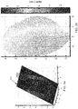
Figures 3 and4 illustrate examples oftilt removal 232 from the 3D TM data. These TM depth maps have been segmented to include only the TM and exclude the ear canal. After the tilt removal, the new representation is registered with respect to tilt (out-of-plane rotation). -
Figures 3a-3d are examples for an AOM eardrum andFigures 4a-4d show a NOE eardrum.Figures 3a and4a show the 3D image of the TM before the tilt removal and also show the bestfit tilt plane Figures 3b and4b show the same 3D image using a color map, with the color of each point being indicative of its depth. Warmer colors indicate parts of the eardrum that are closer to the otoscope, while cooler colors indicate points farther from the otoscope. Because the eardrum is tilted, the depth maps inFigures 3b and4b are dominated by the tilt plane. -
Figures 3c and4c show the 3D image after tilt removal.Figures 3d and4d show the same image but using a similar color code as inFigures 3b and4b but relative to the tilt plane. Warmer colors indicate parts of the eardrum that are higher above the tilt plane and cooler colors indicate parts of the eardrum that are lower below the tilt plane. InFigures 3d and4d , the depth deviations from the tilt plane, which represent the actual shape of the eardrum, are more apparent. - Returning to
Figure 2a ,rotation registration 234 rotates the eardrum image to a standard orientation. In one approach, the standard orientation is defined by a common landmark in the TM anatomy. In the following example, since the TM is tilted towards the inside of the ear canal with the top of the TM lying closest to the otoscope tip, the standard orientation (i.e., zero rotation) is defined by the top of the TM in the ear canal.Figure 5 shows an example of a normal adult TM, along with its 3D reconstruction from 4D LFO data. The lower row inFigure 5 contains superior, inferior, and ventral views both with and without tilt removal. From the ventral view with tilt, we can see that the TM is tilted within the ear canal and that the top of the TM lies closest to the ear canal entrance (where the otoscope tip comes in). One advantage of LFO data is that we have a 3D image and thus we can determine the top of the TM. - To find the zero orientation from the tilt plane, we use the plane elevation vector. We assume that the plane elevation, defined as the projection of the z-axis (as defined by the 3D image before tilt removal) on the tilt plane, is indicative of the top of the eardrum. In
Figures 3a and4a , the green bar (local y-axis) points in the direction of zero orientation.Figure 6 shows examples of 3D depth maps of different TMs, before tilt removal and rotation registration. Warmer colors indicate parts of the eardrum that are closer to the otoscope, while cooler colors indicate points farther from the otoscope. Overlaid on each depth map is an arrow that indicates the direction of the plane elevation vector. The plane elevation vector points to the area of highest depth (the darkest red color). That is, it points to the top of the TM. Since the top of the TM is defined as the zero orientation, the plane elevation vector defines the direction of the y-axis on the plane. Then, given the directions of the y-axis and the normal vector of the plane, we can define the x-axis based on the right-hand rule for Cartesian systems. This is equivalent to rotating the images so that the plane elevation vector is pointing up in all cases. - Since the TMs of the right and left eardrums are mirror-symmetric, we select one of the two as the standard and flip the other so that it is registered correctly relative to the standard form. For example, if the left ear is selected as standard, then we flip the images of the right eardrum. Alternatively, we can flip the left eardrum images if the right ear is chosen as the standard.
- The eardrum depth representation, after the tilt removal and rotation to the zero orientation, is an updated mesh represented by MR = {VR, OR }. At this point, we have registered the 3D TM data with respect to both out-of-plane rotation (tilt) and in-plane rotation (orientation). The next step in registration is to find the
center 236 of the TM. - We use the 3D data to find the center of the TM. In one approach, we designate the location of the umbo as the center of the TM. The umbo is the most depressed part of the TM after tilt removal (i.e., point with most negative depth), as can be seen from
Figure 5 . -
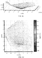
Figure 7 is a flow diagram forcenter localization 236 of an eardrum image, according to various embodiments.Figures 8 and 9 illustrate two examples using this approach. In order to make the computations more efficient, and without loss of generality, we first re-sample and interpolate 710 the mesh MR for the 3D eardrum image to get a new mesh MRR = {VRR, ORR } that has vertices on a regular grid along the two spatial directions x and y. Areas of negative depth are located on MRR by filtering 720 with Gaussian kernels and picking the locations of the vertices with sufficiently negative responses (e.g., below a threshold). These are denoted as VRRN ⊂ VRR. For the examples described below, we have used filters with standard deviation equal to 2 while the value for the threshold was set equal to -0.1. InFigures 8a and 9a , warmer colors indicate parts of the eardrum that are higher above the tilt plane and cooler colors indicate parts of the eardrum that are lower below the tilt plane. The x's inFigures 8a and 9a show the negative depth vertices included in VRRN. InFigure 8a , there are twodisjoint regions Figure 9a , there is oneregion 910. - Using only the negative depth locations VRRN , we usually end up with many neighboring vertices that belong to the same area. We use an additional clustering step for the vertices in VRRN. During the clustering, we would like to take into account the fact that the umbo is usually located in inner areas of the eardrum, i.e., areas that are physically separated from the border of the eardrum. From our observations, we have noticed that such areas often exhibit closed depth isocontours, which are the contours of equal depth.
-
Figure 8b shows 3D eardrum images with isocontours. These isocontours can be calculated 730 using various conventional methods. We examine closed isocontours of the surface, starting from the ones with most negative depth, which are represented by darkest blue inFigure 8b . From these, we create 740 anew cluster 830 for all the vertices in VRRN that lie inside each isocontour. In this way, all the vertices that belong to the same inner eardrum area will be clustered together based on the largest closed isocontour in this area, while the vertices that belong to outer areas of negative depth will remain unclustered.Figure 8c shows thecluster 830 resulting from this isocontour-based clustering. Thecluster 810 of negative vertices inFigure 8a is successfully defined using the approach based on closed isocontours and is included in thecluster 830 ofFigure 8c . However, thenegative vertices 820 are not part of thecentral cluster 810 and are ignored inFigure 8c . Theumbo 850 is identified 790 as the center or centroid of thecentral cluster 810. - There are cases where due to some irregularity in the shape of the eardrum, closed isocontours that overlap with the locations of the vertices in VRRN are not successfully located. Such an example is shown in
Figure 9 . There are no closed isocontours inFigure 9b . For these cases, we employ the k-nearest neighbor (k-NN) graph of the vertices in VRRN to guide the clustering, which we refer to as graph-basedclustering 760. More specifically, we mark the connected components of the k-NN graph as areas of negative depth. An example of the resultingcluster 930 is shown inFigure 9c . Thecenter 950 is identified as the center or centroid of thecluster 930. If there is more than one cluster, then thecenter 950 is the center or centroid of the largest cluster. - Returning to
Figure 2a , images of an eardrum can be captured at different distances, resulting in the TM having different sizes in the image. Also, the physical size of the TM might be different in different patients. To account for these variations, we perform ascale normalization 238 of the TM image. Each eardrum is scaled to match a standard size. Examples of the standard size include the largest eardrum considered, the smallest eardrum considered, and an eardrum of a given size (e.g., width, height and/or area). -
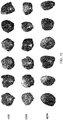
Figure 10 shows examples of TMs that have been automatically registered, using the process described above. Each TM has been reprojected on the tilt plane and rotated such that the zero orientation points upward. We can see that the malleus (the bone visible behind the TM in NOE and OME cases) is at the same position on all images, showing the success of our registration. The different rows show eardrums with NOE, OME and AOM, respectively. According to an aspect of an embodiment, thre is provision for a non-transitory computer-readable storage medium storing executable computer program instructions for automatic classification of eardrums from light field data, the instructions executable by a processor and causing the processor to perform a method including: - producing a three-dimensional image of an eardrum from light field data captured for the eardrum;
- registering the three-dimensional image of the eardrum as defined by a predefined standard form; and
- Although the detailed description contains many specifics, these should not be construed as limiting the scope of the invention but merely as illustrating different examples and aspects of the invention. It should be appreciated that the scope of the invention includes other embodiments not discussed in detail above. Various other modifications, changes and variations which will be apparent to those skilled in the art may be made in the arrangement, operation and details of the method and apparatus of the present invention disclosed herein without departing from the spirit and scope of the invention as defined in the appended claims. Therefore, the scope of the invention should be determined by the appended claims and their legal equivalents.
- Alternate embodiments are implemented in computer hardware, firmware, software, and/or combinations thereof. Implementations can be implemented in a computer program product tangibly embodied in a machine-readable storage device for execution by a programmable processor; and method steps can be performed by a programmable processor executing a program of instructions to perform functions by operating on input data and generating output. Embodiments can be implemented advantageously in one or more computer programs that are executable on a programmable system including at least one programmable processor coupled to receive data and instructions from, and to transmit data and instructions to, a data storage system, at least one input device, and at least one output device. Each computer program can be implemented in a high-level procedural or object-oriented programming language, or in assembly or machine language if desired; and in any case, the language can be a compiled or interpreted language. Suitable processors include, by way of example, both general and special purpose microprocessors. Generally, a processor will receive instructions and data from a read-only memory and/or a random access memory. Generally, a computer will include one or more mass storage devices for storing data files; such devices include magnetic disks, such as internal hard disks and removable disks; magneto-optical disks; and optical disks. Storage devices suitable for tangibly embodying computer program instructions and data include all forms of non-volatile memory, including by way of example semiconductor memory devices, such as EPROM, EEPROM, and flash memory devices; magnetic disks such as internal hard disks and removable disks; magneto-optical disks; and CD-ROM disks. Any of the foregoing can be supplemented by, or incorporated in, ASICs (application-specific integrated circuits) and other forms of hardware.
- The term "module" is not meant to be limited to a specific physical form. Depending on the specific application, modules can be implemented as hardware, firmware, software, and/or combinations of these. Furthermore, different modules can share common components or even be implemented by the same components. There may or may not be a clear boundary between different modules.
Claims (15)
- A method for automatic classification of eardrums from light field data, the method performed by a computer system having a processor and memory, the method comprising:producing a three-dimensional image of an eardrum from light field data captured for the eardrum;registering the three-dimensional image of the eardrum as defined by a predefined standard form; andclassifying the eardrum based on the registered three-dimensional image of the eardrum.
- The method of claim 1
wherein the predefined standard form includes a location of a center of the eardrum, and registering the three-dimensional image of the eardrum comprises determining the location of the center of the eardrum in the three-dimensional image. - The method of claim 2
wherein the center of the eardrum is defined as a location of the umbo, or
wherein the center of the eardrum is defined as a location with a most negative depth. - The method of claim 2
wherein determining the location of the center of the eardrum in the three-dimensional image comprises:selecting a subset of the three-dimensional image of the eardrum that have a depth below a predefined threshold; andanalyzing the selected subset to determine the location of the center of the eardrum. - The method of claim 2
wherein determining the location of the center of the eardrum in the three-dimensional image comprises:identifying depressed areas of the eardrum defined by closed isocontours of negative depth; anddetermining the location of the center of the eardrum based on the identified depressed areas. - The method of claim 5
wherein determining the location of the center of the eardrum further comprises:selecting the largest of the depressed areas; anddetermining the location of the center of the eardrum within the largest depressed area. - The method of claim 2
wherein determining the location of the center of the eardrum in the three-dimensional image comprises:applying graph-based clustering to identify depressed areas of the eardrum; anddetermining the location of the center of the eardrum based on the identified depressed areas. - The method of claim 7
wherein determining the location of the center of the eardrum further comprises:selecting the largest of the depressed areas; anddetermining the location of the center of the eardrum within the largest depressed area. - The method of claim 2
wherein determining the location of the center of the eardrum in the three-dimensional image comprises:identifying first depressed areas defined by closed isocontours of negative depth;if first depressed areas are identified, then determining the location of the center of the eardrum based on the identified first depressed areas;if no first depressed areas are identified, then applying graph-based clustering to identify second depressed areas and determining the location of the center of the eardrum based on the identified second depressed areas. - The method of claim 1
wherein the predefined standard form includes an untilted three-dimensional image of the eardrum, and registering the three-dimensional image of the eardrum comprises removing tilt from the three-dimensional image of the eardrum. - The method of claim 10
wherein removing tilt from the three-dimensional image of the eardrum comprises:determining a plane that is a best fit to the three-dimensional image of the eardrum;calculating a tilt of the best fit plane; andremoving the calculated tilt from the three-dimensional image of the eardrum. - The method of claim 1
wherein the predefined standard form includes a predefined rotational orientation of the three-dimensional image of the eardrum, and registering the three-dimensional image of the eardrum comprises rotating the three-dimensional image of the eardrum to the predefined rotational orientation. - The method of claim 12
wherein the predefined rotational orientation is defined relative to an anatomical landmark on the eardrum, or
wherein the predefined rotational orientation is defined by a tilt of the eardrum in an ear canal. - The method of claim 1
wherein the predefined standard form includes a predefined size of the three-dimensional image of the eardrum, and registering the three-dimensional image of the eardrum comprises scaling the three-dimensional image of the eardrum to match the predefined size,
wherein the predefined standard form identifies left ear or right ear as standard, and registering the three-dimensional image of the eardrum comprises producing a mirror image of the three-dimensional image of the eardrum if the three-dimensional image is not for the standard ear, or
wherein the three-dimensional image of the eardrum is segmented to include only the eardrum and excludes structures beyond the eardrum. - A method for registering a three-dimensional image of the eardrum according to a predefined standard form, the method performed on a computer system having a processor and memory, the method comprising:transforming the three-dimensional image of the eardrum to a predefined spatial orientation; anddetermining a location of the center of the eardrum in the transformed three-dimensional image.
Applications Claiming Priority (1)
| Application Number | Priority Date | Filing Date | Title |
|---|---|---|---|
| US15/452,613 US10296780B2 (en) | 2017-03-07 | 2017-03-07 | Automatic eardrum registration from light field data |
Publications (2)
| Publication Number | Publication Date |
|---|---|
| EP3373244A2 true EP3373244A2 (en) | 2018-09-12 |
| EP3373244A3 EP3373244A3 (en) | 2018-12-19 |
Family
ID=61563137
Family Applications (1)
| Application Number | Title | Priority Date | Filing Date |
|---|---|---|---|
| EP18159173.6A Withdrawn EP3373244A3 (en) | 2017-03-07 | 2018-02-28 | Automatic eardrum registration from light field data |
Country Status (2)
| Country | Link |
|---|---|
| US (1) | US10296780B2 (en) |
| EP (1) | EP3373244A3 (en) |
Families Citing this family (2)
| Publication number | Priority date | Publication date | Assignee | Title |
|---|---|---|---|---|
| US10568515B2 (en) | 2016-06-21 | 2020-02-25 | Otonexus Medical Technologies, Inc. | Optical coherence tomography device for otitis media |
| US10357161B1 (en) * | 2017-05-31 | 2019-07-23 | Otonexus Medical Technologies, Inc. | Infrared otoscope for characterization of effusion |
Citations (4)
| Publication number | Priority date | Publication date | Assignee | Title |
|---|---|---|---|---|
| WO2012058641A2 (en) * | 2010-10-29 | 2012-05-03 | The Regents Of The University Of California | Cellscope apparatus and methods for imaging |
| US20150065803A1 (en) * | 2013-09-05 | 2015-03-05 | Erik Scott DOUGLAS | Apparatuses and methods for mobile imaging and analysis |
| US9460515B2 (en) | 2013-10-25 | 2016-10-04 | Ricoh Co., Ltd. | Processing of light fields by transforming to scale and depth space |
| US9569853B2 (en) | 2013-10-25 | 2017-02-14 | Ricoh Company, Ltd. | Processing of light fields by transforming to scale and depth space |
Family Cites Families (56)
| Publication number | Priority date | Publication date | Assignee | Title |
|---|---|---|---|---|
| US6110106A (en) | 1998-06-24 | 2000-08-29 | Biomax Technologies, Inc. | Endoscopes and methods relating to direct viewing of a target tissue |
| JP2000126116A (en) | 1998-10-28 | 2000-05-09 | Olympus Optical Co Ltd | Photo-diagnosis system |
| JP2001157664A (en) | 1999-12-03 | 2001-06-12 | Asahi Optical Co Ltd | Image sensor for electronic endoscope and electronic endoscope |
| US6483535B1 (en) | 1999-12-23 | 2002-11-19 | Welch Allyn, Inc. | Wide angle lens system for electronic imagers having long exit pupil distances |
| JP2002034916A (en) | 2000-07-24 | 2002-02-05 | Tomio Fujita | Earscope |
| IL155837A0 (en) | 2000-11-16 | 2004-06-01 | Chameleon Medical Innovation L | A diagnostic system for the ear |
| JP2004222870A (en) | 2003-01-21 | 2004-08-12 | Pentax Corp | Endoscope probe |
| US7399275B2 (en) | 2003-07-28 | 2008-07-15 | Welch Allyn, Inc. | Otoscope |
| US8066634B2 (en) | 2003-07-28 | 2011-11-29 | Welch Allyn, Inc. | Digital otoscope |
| CA2581668A1 (en) | 2003-09-26 | 2005-04-07 | Tidal Photonics, Inc | Apparatus and methods relating to expanded dynamic range imaging endoscope systems |
| US7433042B1 (en) | 2003-12-05 | 2008-10-07 | Surface Optics Corporation | Spatially corrected full-cubed hyperspectral imager |
| US7901351B2 (en) | 2003-12-24 | 2011-03-08 | Medical Innovations, Llc | Fiberoptic otoscope system |
| US7698068B2 (en) | 2004-06-17 | 2010-04-13 | Cadent Ltd. | Method for providing data associated with the intraoral cavity |
| WO2006039486A2 (en) | 2004-10-01 | 2006-04-13 | The Board Of Trustees Of The Leland Stanford Junior University | Imaging arrangements and methods therefor |
| US7399375B2 (en) | 2004-12-15 | 2008-07-15 | Judson Leiser | Connecting conduits to components of fluid handling devices |
| JP4826152B2 (en) | 2005-06-23 | 2011-11-30 | 株式会社ニコン | Image composition method and imaging apparatus |
| US7448753B1 (en) | 2005-07-19 | 2008-11-11 | Chinnock Randal B | Portable Digital Medical Camera for Capturing Images of the Retina or the External Auditory Canal, and Methods of Use |
| EP1941314A4 (en) | 2005-10-07 | 2010-04-14 | Univ Leland Stanford Junior | MICROSCOPY ARRANGEMENTS AND TECHNIQUES |
| KR101292728B1 (en) | 2006-11-17 | 2013-08-01 | 삼성전자주식회사 | Optical recording medium, Optical recording medium manufacturing apparatus and method therefor, and recording/reproducing apparatus and method therefor |
| JP5207797B2 (en) | 2008-03-28 | 2013-06-12 | キヤノン株式会社 | Imaging apparatus and control method thereof |
| CN101305899A (en) | 2008-07-09 | 2008-11-19 | 中国科学院上海光学精密机械研究所 | Three-dimensional endoscopic measurement device and method based on amplitude-type transmission grating projection |
| PT104131B (en) | 2008-07-14 | 2010-10-20 | Univ Do Porto | DEVICE FOR MEASURING AND ANALYZING THE COLOR OF THE EXTERNAL EAR AND HEARING CHANNEL |
| US9291565B2 (en) | 2008-07-24 | 2016-03-22 | Massachusetts Institute Of Technology | Three dimensional scanning using membrane with optical features |
| US8845526B2 (en) | 2008-07-24 | 2014-09-30 | Massachusetts Institute Of Technology | Integrated otoscope and three dimensional scanning system |
| US9170199B2 (en) | 2008-07-24 | 2015-10-27 | Massachusetts Institute Of Technology | Enhanced sensors in three dimensional scanning system |
| US9170200B2 (en) | 2008-07-24 | 2015-10-27 | Massachusetts Institute Of Technology | Inflatable membrane with hazard mitigation |
| US9140649B2 (en) | 2008-07-24 | 2015-09-22 | Massachusetts Institute Of Technology | Inflatable membrane having non-uniform inflation characteristic |
| ES2649488T3 (en) | 2008-07-24 | 2018-01-12 | Massachusetts Institute Of Technology | Systems and methods for obtaining images using absorption |
| RU2011122642A (en) | 2008-11-04 | 2012-12-20 | Уилльям Марш Райз Юниверсити | SPECTROMETERS WITH IMAGE MAPPING FUNCTION |
| US7995214B2 (en) | 2009-07-28 | 2011-08-09 | Siemens Medical Instruments Pte. Ltd. | Apparatus and method for recording the shape of an ear section |
| US8143565B2 (en) | 2009-09-30 | 2012-03-27 | Ricoh Co., Ltd. | Adjustable multimode lightfield imaging system having an actuator for changing position of a non-homogeneous filter module relative to an image-forming optical module |
| EP2635174B1 (en) | 2010-11-04 | 2019-07-03 | The Cleveland Clinic Foundation | Device for determining the presence of middle ear fluid |
| US8908087B2 (en) | 2010-11-16 | 2014-12-09 | Nikon Corporation | Multiband camera, and multiband image capturing method |
| US9250131B2 (en) | 2011-01-17 | 2016-02-02 | Ricoh Co., Ltd. | Multi-imaging system with interleaved images |
| US8949078B2 (en) | 2011-03-04 | 2015-02-03 | Ricoh Co., Ltd. | Filter modules for aperture-coded, multiplexed imaging systems |
| KR101223283B1 (en) | 2011-03-08 | 2013-01-21 | 경북대학교 산학협력단 | Diagnostic display and operating intergrated optical tomography otoscope |
| US20120320340A1 (en) | 2011-06-18 | 2012-12-20 | Intuitive Medical Technologies, Llc | Smart-phone adapter for ophthalmoscope |
| JP6073883B2 (en) | 2011-07-28 | 2017-02-01 | マサチューセッツ インスティテュート オブ テクノロジー | Configuration of camera for 3D imaging of internal space |
| ES2442178B2 (en) | 2011-10-20 | 2014-07-30 | Asociacion Industrial De Optica, Color E Imagen - Aido | MULTI-PERSPECTIVE EYE BACKGROUND CAMERA. |
| US8944596B2 (en) | 2011-11-09 | 2015-02-03 | Welch Allyn, Inc. | Digital-based medical devices |
| US9001326B2 (en) | 2011-12-13 | 2015-04-07 | Welch Allyn, Inc. | Method and apparatus for observing subsurfaces of a target material |
| US8824779B1 (en) | 2011-12-20 | 2014-09-02 | Christopher Charles Smyth | Apparatus and method for determining eye gaze from stereo-optic views |
| US8900125B2 (en) | 2012-03-12 | 2014-12-02 | United Sciences, Llc | Otoscanning with 3D modeling |
| US9565993B2 (en) | 2012-05-17 | 2017-02-14 | Pioneer Corporation | Endoscope |
| US9636007B2 (en) | 2012-08-03 | 2017-05-02 | Carnegie Mellon University | Method and apparatus for aiding in the diagnosis of otitis media by classifying tympanic membrane images |
| KR20140049137A (en) * | 2012-10-12 | 2014-04-25 | 삼성전자주식회사 | Medical image analyzing apparatus and method |
| US9219866B2 (en) | 2013-01-07 | 2015-12-22 | Ricoh Co., Ltd. | Dynamic adjustment of multimode lightfield imaging system using exposure condition and filter position |
| US10327627B2 (en) | 2013-01-18 | 2019-06-25 | Ricoh Company, Ltd. | Use of plenoptic otoscope data for aiding medical diagnosis |
| US9565996B2 (en) | 2013-01-18 | 2017-02-14 | Ricoh Company, Ltd. | Plenoptic otoscope |
| US20140378810A1 (en) | 2013-04-18 | 2014-12-25 | Digimarc Corporation | Physiologic data acquisition and analysis |
| WO2014190091A1 (en) | 2013-05-21 | 2014-11-27 | Steven Verdooner | System and method for imaging a patient user's body part |
| US9706116B2 (en) | 2013-10-31 | 2017-07-11 | Ricoh Co., Ltd. | Plenoptic color imaging system with enhanced resolution |
| US9392933B2 (en) * | 2014-03-06 | 2016-07-19 | Ricoh Company, Ltd. | Otoscope illumination |
| US9888229B2 (en) | 2014-06-23 | 2018-02-06 | Ricoh Company, Ltd. | Disparity estimation for multiview imaging systems |
| US20170119237A1 (en) | 2015-10-28 | 2017-05-04 | Ricoh Company, Ltd. | Optical Design of a Light Field Otoscope |
| US10098529B2 (en) * | 2015-10-28 | 2018-10-16 | Ricoh Company, Ltd. | Optical design of a light field otoscope |
-
2017
- 2017-03-07 US US15/452,613 patent/US10296780B2/en not_active Expired - Fee Related
-
2018
- 2018-02-28 EP EP18159173.6A patent/EP3373244A3/en not_active Withdrawn
Patent Citations (4)
| Publication number | Priority date | Publication date | Assignee | Title |
|---|---|---|---|---|
| WO2012058641A2 (en) * | 2010-10-29 | 2012-05-03 | The Regents Of The University Of California | Cellscope apparatus and methods for imaging |
| US20150065803A1 (en) * | 2013-09-05 | 2015-03-05 | Erik Scott DOUGLAS | Apparatuses and methods for mobile imaging and analysis |
| US9460515B2 (en) | 2013-10-25 | 2016-10-04 | Ricoh Co., Ltd. | Processing of light fields by transforming to scale and depth space |
| US9569853B2 (en) | 2013-10-25 | 2017-02-14 | Ricoh Company, Ltd. | Processing of light fields by transforming to scale and depth space |
Also Published As
| Publication number | Publication date |
|---|---|
| US20180260611A1 (en) | 2018-09-13 |
| EP3373244A3 (en) | 2018-12-19 |
| US10296780B2 (en) | 2019-05-21 |
Similar Documents
| Publication | Publication Date | Title |
|---|---|---|
| US10327627B2 (en) | Use of plenoptic otoscope data for aiding medical diagnosis | |
| CN106066696B (en) | Gaze tracking method based on projection mapping correction and gaze compensation under natural light | |
| Joshi et al. | Depth discontinuity-based cup segmentation from multiview color retinal images | |
| JP4184842B2 (en) | Image discrimination device, method and program | |
| EP2526762A1 (en) | Arrangement and method for determining positions of the teats of a milking animal | |
| EP3086705A1 (en) | Wide field retinal image capture system and method | |
| Hussain et al. | Augmented reality for inner ear procedures: visualization of the cochlear central axis in microscopic videos | |
| US20170119237A1 (en) | Optical Design of a Light Field Otoscope | |
| Korotkov et al. | An improved skin lesion matching scheme in total body photography | |
| CN109166177A (en) | Air navigation aid in a kind of art of craniomaxillofacial surgery | |
| CN104933432A (en) | Processing method for finger pulp crease and finger vein images | |
| CN110782434B (en) | An intelligent marking and positioning device for brain tuberculosis MRI image lesions | |
| CN118977137A (en) | An automatic tool adjustment method for inspection machine based on visual recognition | |
| EP3373198A1 (en) | Automatic classification of eardrum shape | |
| US10296780B2 (en) | Automatic eardrum registration from light field data | |
| CN110264510A (en) | A method of image zooming-out depth of view information is acquired based on binocular | |
| CN116188554A (en) | A three-dimensional imaging method and device based on binocular stereo measuring endoscope | |
| JP5134287B2 (en) | Medical image display device, medical image display method, program, storage medium, and mammography device | |
| Joshi et al. | Vessel bend-based cup segmentation in retinal images | |
| WO2017046377A1 (en) | Method and computer program product for processing an examination record comprising a plurality of images of at least parts of at least one retina of a patient | |
| CN120431049B (en) | A Method and System for Estimating Polyp Image Size Based on Deep Learning Model | |
| EP3804608B1 (en) | System, method, and computer program for rejecting full and partial blinks for retinal tracking | |
| EP3224802B1 (en) | Image processing apparatus and method | |
| JP2018149234A (en) | Fixation point estimation system, fixation point estimation method, and fixation point estimation program | |
| CN115841668B (en) | A method for binocular vision apple recognition and precise positioning |
Legal Events
| Date | Code | Title | Description |
|---|---|---|---|
| PUAI | Public reference made under article 153(3) epc to a published international application that has entered the european phase |
Free format text: ORIGINAL CODE: 0009012 |
|
| 17P | Request for examination filed |
Effective date: 20180228 |
|
| AK | Designated contracting states |
Kind code of ref document: A2 Designated state(s): AL AT BE BG CH CY CZ DE DK EE ES FI FR GB GR HR HU IE IS IT LI LT LU LV MC MK MT NL NO PL PT RO RS SE SI SK SM TR |
|
| AX | Request for extension of the european patent |
Extension state: BA ME |
|
| PUAL | Search report despatched |
Free format text: ORIGINAL CODE: 0009013 |
|
| AK | Designated contracting states |
Kind code of ref document: A3 Designated state(s): AL AT BE BG CH CY CZ DE DK EE ES FI FR GB GR HR HU IE IS IT LI LT LU LV MC MK MT NL NO PL PT RO RS SE SI SK SM TR |
|
| AX | Request for extension of the european patent |
Extension state: BA ME |
|
| RIC1 | Information provided on ipc code assigned before grant |
Ipc: G06T 7/00 20170101AFI20181115BHEP Ipc: G06T 7/33 20170101ALI20181115BHEP Ipc: A61B 1/227 20060101ALI20181115BHEP |
|
| RAP1 | Party data changed (applicant data changed or rights of an application transferred) |
Owner name: RICOH COMPANY, LTD. |
|
| 17Q | First examination report despatched |
Effective date: 20200921 |
|
| STAA | Information on the status of an ep patent application or granted ep patent |
Free format text: STATUS: THE APPLICATION HAS BEEN WITHDRAWN |
|
| 18W | Application withdrawn |
Effective date: 20201222 |