EP3373056A1 - Optical fiber tape, method for manufacturing optical fiber tape, and ultraviolet curable resin composition used to form connection portions of intermittently fixed optical fiber tape - Google Patents
Optical fiber tape, method for manufacturing optical fiber tape, and ultraviolet curable resin composition used to form connection portions of intermittently fixed optical fiber tape Download PDFInfo
- Publication number
- EP3373056A1 EP3373056A1 EP16858479.5A EP16858479A EP3373056A1 EP 3373056 A1 EP3373056 A1 EP 3373056A1 EP 16858479 A EP16858479 A EP 16858479A EP 3373056 A1 EP3373056 A1 EP 3373056A1
- Authority
- EP
- European Patent Office
- Prior art keywords
- optical fiber
- curable resin
- meth
- acrylate
- optical fibers
- Prior art date
- Legal status (The legal status is an assumption and is not a legal conclusion. Google has not performed a legal analysis and makes no representation as to the accuracy of the status listed.)
- Granted
Links
Images
Classifications
-
- G—PHYSICS
- G02—OPTICS
- G02B—OPTICAL ELEMENTS, SYSTEMS OR APPARATUS
- G02B6/00—Light guides; Structural details of arrangements comprising light guides and other optical elements, e.g. couplings
- G02B6/44—Mechanical structures for providing tensile strength and external protection for fibres, e.g. optical transmission cables
- G02B6/4479—Manufacturing methods of optical cables
- G02B6/448—Ribbon cables
-
- B—PERFORMING OPERATIONS; TRANSPORTING
- B29—WORKING OF PLASTICS; WORKING OF SUBSTANCES IN A PLASTIC STATE IN GENERAL
- B29D—PRODUCING PARTICULAR ARTICLES FROM PLASTICS OR FROM SUBSTANCES IN A PLASTIC STATE
- B29D11/00—Producing optical elements, e.g. lenses or prisms
- B29D11/00663—Production of light guides
-
- B—PERFORMING OPERATIONS; TRANSPORTING
- B29—WORKING OF PLASTICS; WORKING OF SUBSTANCES IN A PLASTIC STATE IN GENERAL
- B29D—PRODUCING PARTICULAR ARTICLES FROM PLASTICS OR FROM SUBSTANCES IN A PLASTIC STATE
- B29D11/00—Producing optical elements, e.g. lenses or prisms
- B29D11/00663—Production of light guides
- B29D11/00721—Production of light guides involving preforms for the manufacture of light guides
-
- C—CHEMISTRY; METALLURGY
- C08—ORGANIC MACROMOLECULAR COMPOUNDS; THEIR PREPARATION OR CHEMICAL WORKING-UP; COMPOSITIONS BASED THEREON
- C08F—MACROMOLECULAR COMPOUNDS OBTAINED BY REACTIONS ONLY INVOLVING CARBON-TO-CARBON UNSATURATED BONDS
- C08F2/00—Processes of polymerisation
- C08F2/46—Polymerisation initiated by wave energy or particle radiation
- C08F2/48—Polymerisation initiated by wave energy or particle radiation by ultraviolet or visible light
-
- G—PHYSICS
- G02—OPTICS
- G02B—OPTICAL ELEMENTS, SYSTEMS OR APPARATUS
- G02B6/00—Light guides; Structural details of arrangements comprising light guides and other optical elements, e.g. couplings
- G02B6/44—Mechanical structures for providing tensile strength and external protection for fibres, e.g. optical transmission cables
-
- G—PHYSICS
- G02—OPTICS
- G02B—OPTICAL ELEMENTS, SYSTEMS OR APPARATUS
- G02B6/00—Light guides; Structural details of arrangements comprising light guides and other optical elements, e.g. couplings
- G02B6/44—Mechanical structures for providing tensile strength and external protection for fibres, e.g. optical transmission cables
- G02B6/4401—Optical cables
- G02B6/4403—Optical cables with ribbon structure
-
- B—PERFORMING OPERATIONS; TRANSPORTING
- B29—WORKING OF PLASTICS; WORKING OF SUBSTANCES IN A PLASTIC STATE IN GENERAL
- B29K—INDEXING SCHEME ASSOCIATED WITH SUBCLASSES B29B, B29C OR B29D, RELATING TO MOULDING MATERIALS OR TO MATERIALS FOR MOULDS, REINFORCEMENTS, FILLERS OR PREFORMED PARTS, e.g. INSERTS
- B29K2083/00—Use of polymers having silicon, with or without sulfur, nitrogen, oxygen, or carbon only, in the main chain, as moulding material
-
- G—PHYSICS
- G02—OPTICS
- G02B—OPTICAL ELEMENTS, SYSTEMS OR APPARATUS
- G02B6/00—Light guides; Structural details of arrangements comprising light guides and other optical elements, e.g. couplings
- G02B6/44—Mechanical structures for providing tensile strength and external protection for fibres, e.g. optical transmission cables
- G02B6/4479—Manufacturing methods of optical cables
- G02B6/4486—Protective covering
Definitions
- the present invention relates to an optical fiber ribbon, a method for manufacturing an optical fiber ribbon, and a UV-curable resin composition used for the formation of connections part in an intermittently connected optical fiber ribbon.
- Patent Literature 1 discloses an optical fiber ribbon (intermittently connected optical fiber ribbon) in which a plurality of optical fibers are arranged side by side and connected intermittently.
- Patent Literatures 2 and 3 disclose methods for manufacturing such intermittently connected optical fiber ribbons. More specifically, Patent Literatures 2 and 3 describe the manufacture of an intermittently connected optical fiber ribbon by: applying a curable resin between adjacent optical fibers; blocking the still-uncured curable resin to form non-connected parts (separated parts) between the optical fibers; and curing the curable resin during a period before the optical fibers are gathered together.
- An objective of the invention is to form connection parts and non-connected parts of an intermittently connected optical fiber ribbon as designed.
- a primary aspect of the invention for achieving the aforementioned objective is an intermittently connected optical fiber ribbon including: a plurality of optical fibers arranged side by side; and connection parts arranged intermittently and each connecting two adjacent ones of the optical fibers, the connection part being formed by curing a UV-curable resin including a siloxane structure in its molecule.
- This invention allows connection parts and non-connected parts of an intermittently connected optical fiber ribbon to be formed as designed.
- an intermittently connected optical fiber ribbon including: a plurality of optical fibers arranged side by side; and connection parts arranged intermittently and each connecting two adjacent ones of the optical fibers, the connection part being formed by curing a UV-curable resin including a siloxane structure in its molecule.
- the aforementioned UV-curable resin includes a urethane oligomer including the aforementioned siloxane structure.
- this intermittently connected optical fiber ribbon, connection parts and non-connected parts can be formed as designed.
- the aforementioned UV-curable resin includes a reactive monomer including the aforementioned siloxane structure.
- this intermittently connected optical fiber ribbon, connection parts and non-connected parts can be formed as designed.
- an intermittently connected optical fiber ribbon that includes a plurality of optical fibers arranged side by side, and connection parts arranged intermittently and each connecting two adjacent ones of the optical fibers, the method involving: a step of applying, between the optical fibers, a UV-curable resin including a siloxane structure in its molecule; a step of removing a portion of the UV-curable resin applied between the optical fibers; and a step of irradiating the UV-curable resin between the optical fibers with UV rays and forming the connection parts.
- connection parts and non-connected parts of an intermittently connected optical fiber ribbon can be formed as designed.
- connection parts that are intermittently arranged to connect two adjacent ones of optical fibers in an intermittently connected optical fiber ribbon
- the UV-curable resin composition including a siloxane structure in its molecule.
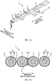
- Fig. 1A is a perspective view of an intermittently connected optical fiber ribbon 1.
- Fig. 1B is a cross-sectional view taken along line A-A of Fig. 1A .
- the various directions are defined as illustrated in Fig. 1A .
- the direction parallel to the optical fibers 3 constituting the optical fiber ribbon 1 (the direction of the optical axis of the optical fiber 3) is also referred to as the "length direction”.
- the direction in which the plurality of optical fibers 3 constituting the optical fiber ribbon 1 are arranged is also referred to as the "ribbon's width direction”.
- the intermittently connected optical fiber ribbon 1 is an optical fiber ribbon 1 including a plurality of optical fibers 3 (four in this example) arranged side by side and connected intermittently. Two adjacent ones of the optical fibers 3 are connected by a connection part 5. Between two adjacent optical fibers, a plurality of connection parts 5 are arranged intermittently in the length direction. The plurality of connection parts 5 of the intermittently connected optical fiber ribbon 1 are arranged intermittently and two-dimensionally in the length direction and the ribbon's width direction. Regions other than the connection parts 5 between the two adjacent optical fibers constitute non-connected parts 7 (separated parts). In the non-connected parts 7, the two adjacent optical fibers 3 are not restrained. Thus, the intermittently connected optical fiber ribbon 1 can be rolled up into a cylindrical form, or folded up, and the multitude of optical fibers 3 can be bundled with high density.
- the intermittently connected optical fiber ribbon 1 is not limited to the example illustrated in Fig. 1A .
- the number of optical fibers 3 constituting the optical fiber ribbon 1 may be changed.
- the connection part 5 is formed at length L1
- a region without any connection parts 5 is formed at length L2
- the connection parts 5 are arranged intermittently in the length direction at an interval of length L3, but the lengths and arrangement of the connection parts 5 can be changed.
- the optical fiber 3 (jacketed optical fiber) includes a glass fiber 3A and a cover layer 3B.
- the outer periphery of the optical fiber 3 is coated with a connecting agent 9 (UV-curable resin).
- a connecting agent 9 UV-curable resin
- Two adjacent optical fibers 3 are connected at the connection parts 5 by the connecting agent 9 that coats the outer periphery of each optical fiber 3.
- the connecting agent 9 constituting the connection parts 5 is described further below.
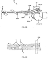
- Fig. 2A is a diagram illustrating a device for manufacturing the intermittently connected optical fiber ribbon 1 (ribbon manufacturing device) .
- Fig. 2B is a diagram illustrating how optical fibers 3 are gathered after application of the connecting agent 9.
- the ribbon manufacturing device includes an application section, a removal section, and a light source.
- the application section is a device that applies the connecting agent 9 (UV-curable resin).
- the application section applies the connecting agent 9, which is in liquid-form, onto the outer periphery of each optical fiber 3 and between the optical fibers.
- the removal section is a device that removes a portion of the liquid-form connecting agent 9 (UV-curable resin) applied between the optical fibers while leaving a portion of the connecting agent.
- the removal section includes rotary blades each having a recess. The rotary blades rotate in accordance with the supply speed of the optical fibers 3, and the rotary blades remove (cut) the connecting agent 9 applied between the optical fibers while leaving the connecting agent 9 at the recesses.
- the light source is an irradiation device that irradiates the connecting agent 9 (UV-curable resin), which has been applied onto the outer periphery of each optical fiber 3 and between the optical fibers, with UV rays.
- the light source includes a temporary curing light source and a permanent curing light source.
- the temporary curing light source temporarily cures the connecting agent 9 by irradiating it with UV rays.
- the temporarily cured connecting agent 9 is not yet completely cured, but is in a state where curing has proceeded on the surface thereof.
- the permanent curing light source permanently cures the connecting agent 9 by irradiating it with stronger UV rays than those of the temporary curing light source.
- the permanently cured UV-curable resin is cured to the inside. (The permanently cured UV-curable resin, however, has moderate elasticity to allow the intermittently connected optical fiber ribbon 1 to be rolled up into a cylindrical form or folded up).
- the optical fibers 3 immediately after exiting the application section and the removal section are spaced apart from one another.
- the temporary curing light source irradiates the connecting agent 9 (UV-curable resin) with UV rays, to temporarily cure the connecting agent 9.
- the connecting agent 9 UV-curable resin
- the distance between the optical fibers 3 is gradually reduced, and the plurality of optical fibers 3 are arranged side by side and gathered into a ribbon-form. Note that, because the connecting agent 9 has been temporarily cured, even if parts where the connecting agent 9 has been removed (i.e., the separated parts) come into contact with one another, these parts do not get connected.
- the connecting agent has not been permanently cured yet, the distance between the optical fibers 3 can be narrowed (i.e., the fibers can be gathered) even in regions connected by the connecting agent 9.
- the connecting agent By irradiating the connecting agent with UV rays by the permanent curing light source and permanently curing the connecting agent 9, the intermittently connected optical fiber ribbon 1 illustrated in Fig. 1A is manufactured.
- the UV-curable resin is removed (cut) by rotating the rotary blades.
- the shearing force caused by the rotary blades may reduce the viscosity of the liquid-form connecting agent 9.
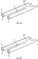
- Figs. 3A and 3B are diagrams illustrating the effect of reduction in viscosity of the connecting agent 9.
- the viscosity of the connecting agent 9 drops at the time of removal of the connecting agent 9, even when a separated part is formed by removing the connecting agent 9 as illustrated in Fig. 3A , the separated part may get connected as illustrated in Fig. 3B . Stated differently, a reduction in the viscosity of the connecting agent 9 may cause a region connected by the connecting agent 9 to flow and spread out. If the separated part (section where the connecting agent 9 has been removed) gets connected, the length of the connection part 5 of the intermittently connected optical fiber ribbon 1 (the length L1 illustrated in Fig. 1A ) becomes longer.
- a connecting agent 9 (UV-curable resin) including a siloxane structure in its molecule is used for forming the connection parts 5 of the intermittently connected optical fiber ribbon 1. Because the connecting agent 9 includes a siloxane structure in its molecule, viscosity reduction can be suppressed at the time of removing the connecting agent 9, and the separated parts (parts where the connecting agent 9 has been removed) can be prevented from getting connected. Stated differently, shape retainability of the connecting agent 9 immediately after removal by the removal section is improved, and regions connected by the connecting agent 9 can be prevented from flowing and spreading out.
- the connecting agent 9 of the present embodiment does not encompass connecting agents in which silicone is simply added to a resin without being cross-linked. Note that, when an intermittently connected optical fiber ribbon 1 is manufactured by using a connecting agent in which silicone is simply added to resin without being cross-linked, the surface stays sticky (in an adhesive state), even after the connecting agent has been cured.
- the connecting agent 9 of the present embodiment is a UV-curable resin that includes a urethane oligomer including a siloxane structure.
- the urethane oligomer including a siloxane structure is made by reacting: a silicone compound that includes, in its molecule, a siloxane structure including one or more hydroxyl groups; an acrylate including a hydroxyl group; and an isocyanate.
- Examples of the aforementioned silicone compound that includes a siloxane structure including hydroxyl group(s) include ⁇ -[3-(2'-hydroxyethoxy)propyl]- ⁇ -trimethylsilyloxy polydimethylsiloxane, ⁇ -[3-(2'-hydroxyethoxy)propyl]- ⁇ -trimethylsilyloxy polydiphenylsiloxane, ⁇ -[3-(2',3'-dihydroxypropyloxy)propyl]- ⁇ -trimethylsilylox y polydimethylsiloxane, ⁇ -[3-(2',3'-dihydroxypropyloxy)propyl]- ⁇ -trimethylsilylox y polydiphenylsiloxane, ⁇ -[3-(2'-ethyl-2'-hydroxymethyl-3-hydroxy)propyl]- ⁇ -trime thylsilyloxy polydimethylsiloxane, ⁇ -[3-(2'-
- the aforementioned silicone compound that includes a siloxane structure including hydroxyl group(s) is also available as commercially available products, such as Silaplane FM-0411, FM-0413, FM-0415, FM-0421, FM-0425, FM-D411, FM-D421, and FM-D425 (all manufactured by Chisso Corporation), and Shin-Etsu Silicone X-22-170A, X-22-170B, X-22-170D, X-22-176B, X-22-176D, X-22-176DX, X-22-178A, and X-22-178B (all manufactured by Shin-Etsu Chemical Co., Ltd.).
- R 1 represents a hydrogen atom or a methyl group
- n represents a number from 1 to 15.
- a compound obtained through an addition reaction between (meth)acrylic acid and a compound including a glycidyl group such as an alkyl glycidyl ether, an allyl glycidyl ether, or glycidyl (meth)acrylate.
- a compound including a glycidyl group such as an alkyl glycidyl ether, an allyl glycidyl ether, or glycidyl (meth)acrylate.
- acrylates including a hydroxyl group 2-hydroxyethyl (meth)acrylate and 2-hydroxypropyl (meth) acrylate are preferred.
- One type of the aforementioned compound may be used alone, or two or more types may be used in combination.
- isocyanate examples include 2,4-tolylene diisocyanate, 2,6-tolylene diisocyanate, 1,3-xylylene diisocyanate, 1,4-xylylene diisocyanate, 1,5-naphthalene diisocyanate, m-phenylene diisocyanate, p-phenylene diisocyanate, 3,3'-dimethyl-4,4'-diphenylmethane diisocyanate, 4,4'-diphenylmethane diisocyanate, 3,3'-dimethylphenylene diisocyanate, 4,4'-biphenylene diisocyanate, 1,6-hexane diisocyanate, isophorone diisocyanate, methylene bis(4-cyclohexyl isocyanate), 2,2,4-trimethylhexamethylene diisocyanate, bis(2-isocyanate ethyl)fumarate, 6-isopropyl-1,3
- 2,4-tolylene diisocyanate, isophorone diisocyanate, xylylene diisocyanate, and methylene bis(4-cyclohexyl isocyanate) are preferred.
- One type of the aforementioned compound may be used alone, or two or more types may be used in combination.
- Examples of reactions for obtaining the aforementioned urethane oligomer include: methods of reacting the aforementioned silicone compound, the acrylate including a hydroxyl group, and the isocyanate by placing them in a single batch; methods of reacting the silicone compound and the isocyanate, and then reacting the acrylate including a hydroxyl group; and methods of reacting the polyisocyanate and the acrylate including a hydroxyl group, and then reacting the silicone compound. It is preferable to perform the reaction such that the hydroxyl group equivalent of the silicone compound including hydroxyl group(s) and of the acrylate including a hydroxyl group substantially matches the isocyanate equivalent of the polyisocyanate.
- polyols usable herein include polyether diols, polyester diols, polycarbonate diols, and polycaprolactone diols. Two or more types of these polyols may be used in combination.
- the bonding manner of the structural units in the polyol is not particularly limited, and may either be random bonding, block bonding, or graft bonding.
- polyether diols examples include polyethylene glycol, polypropylene glycol, polytetramethylene glycol, polyhexamethylene glycol, polyheptamethylene glycol, polydecamethylene glycol, and polyether diols obtained by subjecting at least two types of ionically polymerizable cyclic compounds to ring-opening copolymerization.
- Examples of the ionically polymerizable cyclic compounds include cyclic ethers, such as ethylene oxide, propylene oxide, butene-1-oxide, isobutene oxide, 3,3-bischloromethyloxetane, tetrahydrofuran, 2-methyltetrahydrofuran, 3-methyltetrahydrofuran, dioxane, trioxane, tetraoxane, cyclohexene oxide, styrene oxide, epichlorohydrin, glycidyl methacrylate, allyl glycidyl ether, allyl glycidyl carbonate, butadiene monooxide, isoprene monooxide, vinyloxetane, vinyltetrahydrofuran, vinylcyclohexene oxide, phenyl glycidyl ether, butyl glycidyl ether, and benzoic acid glycidyl ester.
- Examples of concrete combinations of the aforementioned two or more types of ionically polymerizable cyclic compounds include: tetrahydrofuran and propylene oxide; tetrahydrofuran and 2-methyltetrahydrofuran; tetrahydrofuran and 3-methyltetrahydrofuran; tetrahydrofuran and ethylene oxide; propylene oxide and ethylene oxide; butene-1-oxide and ethylene oxide; and a terpolymer of tetrahydrofuran, butene-1-oxide, and ethylene oxide.
- a polyether diol obtained by subjecting, to ring-opening copolymerization, the aforementioned ionically polymerizable cyclic compound and a cyclic imine such as ethylene imine, a cyclic lactone such as ⁇ -propiolactone or glycolic acid lactide, or a dimethylcyclopolysiloxane.
- a cyclic imine such as ethylene imine, a cyclic lactone such as ⁇ -propiolactone or glycolic acid lactide, or a dimethylcyclopolysiloxane.
- the ring-opened copolymers of these ionically polymerizable cyclic compounds may be random-bonded or block-bonded.
- the connecting agent 9 of the present embodiment may also include a reactive monomer.
- the reactive monomer may be a monofunctional monomer or a polyfunctional monomer.
- monofunctional monomers include: vinyl group-containing monomers such as N-vinylpyrrolidone, N-vinylcaprolactam, vinylimidazole, and vinylpyridine; and (meth)acryloyl group-containing monomers such as isobornyl (meth)acrylate, bornyl(meth)acrylate, tricyclodecanyl (meth)acrylate, dicyclopentanyl(meth)acrylate, dicyclopentenyl(meth)acrylate, cyclohexyl(meth)acrylate, benzyl(meth)acrylate, 4-butylcyclohexyl(meth)acrylate, acryloylmorpholine, 2-hydroxyethyl(meth)acrylate, 2-hydroxypropyl(meth)acrylate, 2-hydroxybutyl (meth)acrylate, methyl(meth)acrylate, ethyl(meth)acrylate, propyl(meth)acrylate, isopropyl(meth)acrylate
- R 2 represents a hydrogen atom or a methyl group
- R 3 represents a C 2-6 , preferably C 2-4 alkylene group
- R 4 represents a hydrogen atom or a C 1-12 , preferably C 1-9 alkyl group
- m represents a number from 0 to 12, preferably from 1 to 8.
- R 2 has the same meaning as above, R 5 represents a C 2-8 , preferably C 2-5 alkylene group, and p represents a number from 1 to 8, preferably from 1 to 4.
- R 2 , R 5 , and p have the same meaning as above, and R 6 represents a hydrogen atom or a methyl group.
- R 6 represents a hydrogen atom or a methyl group.
- Examples of commercially available products include: Aronix M-111, M-113, M-114, and M-117 (all manufactured by Toagosei Co., Ltd.); KAYARAD TC110S, R629, and R644 (all manufactured by Nippon Kayaku Co., Ltd.); and Viscoat 3700 (manufactured by Osaka Organic Chemical Industry Ltd.).
- polyfunctional monomers include (meth)acryloyl group-containing monomers, such as trimethylol propane tri(meth)acrylate, pentaerythritol tri(meth)acrylate, ethylene glycol di(meth)acrylate, tetraethylene glycol di(meth)acrylate, polyethylene glycol di(meth)acrylate, 1,4-butanediol di(meth)acrylate, 1,6-hexanediol di(meth)acrylate, neopentyl glycol di(meth)acrylate, trimethylol propane trioxyethyl (meth)acrylate, tris(2-hydroxyethyl)isocyanurate tri(meth)acrylate, tris(2-hydroxyethyl)isocyanurate di(meth)acrylate, tricyclodecanediyldimethyl di(meth)acrylate, a di(meth)acrylate of a diol of Bisphenol A ethylene oxide a
- Examples of commercially available products include: Yupimer UV SA1002 and SA2007 (both manufactured by Mitsubishi Chemical Corporation); Viscoat 700 (manufactured by Osaka Organic Chemical Industry Ltd.); KAYARAD R-604, DPCA-20, -30, -60, -120, HX-620, D-310, and D-330 (all manufactured by Nippon Kayaku Co., Ltd.); and Aronix M-210, M-215, M-315, and M-325 (all manufactured by Toagosei Co., Ltd.).
- tricyclodecanediyldimethyl diacrylate and a diacrylate of polyoxyalkylenated Bisphenol A are preferred.
- the connecting agent 9 of the present embodiment may include a photopolymerization initiator.
- a photopolymerization initiator By adding a photopolymerization initiator to the connecting agent 9, the connecting agent can be cured when irradiated with UV rays.
- photopolymerization initiators examples include 1-hydroxycyclohexyl phenyl ketone, 2,2-dimethoxy-2-phenylacetophenone, xanthone, fluorenone, benzaldehyde, fluorene, anthraquinone, triphenylamine, carbazole, 3-methylacetophenone, 4-chlorobenzophenone, 4,4'-dimethoxybenzophenone, 4,4'-diaminobenzophenone, Michler's ketone, benzoin propyl ether, benzoin ethyl ether, benzyl dimethyl ketal, 1-(4-isopropylphenyl)-2-hydroxy-2-methylpropan-1-one, 2-hydroxy-2-methyl-1-phenylpropan-1-one, thioxanthone, diethylthioxanthone, 2-isopropylthioxanthone, 2-chlorothioxanthone, 2-methyl-1-[4-
- the connecting agent 9 may include a photosensitizer, as necessary.
- photosensitizers include triethylamine, diethylamine, N-methyldiethanol amine, ethanol amine, 4-dimethylaminobenzoic acid, methyl 4-dimethylaminobenzoate, ethyl 4-dimethylaminobenzoate, and isoamyl 4-dimethylaminobenzoate; and Ubecryl P102, 103, 104, and 105 (all manufactured by UCB).
- antioxidants include: Irganox 1010, 1035, 1076, and 1222 (all manufactured by Ciba-Geigy); and Antigen P, 3C, FR, and GA-80 (manufactured by Sumitomo Chemical Industry Company Limited).
- the connecting agent 9 may be a UV-curable resin that includes a reactive monomer including a siloxane structure.
- a reactive monomer including a siloxane structure examples include the compounds described above.
- reactive monomers examples include the monomers described above.
- the connecting agent 9 includes a reactive monomer including a siloxane structure, the aforementioned photopolymerization initiator, photosensitizer, and various types of additives (antioxidants, etc.) may be added thereto.
- the connecting agent 9 (UV-curable resin) including a siloxane structure in its molecule is made by adding, to a UV-curable resin serving as a base agent, the aforementioned compound (a liquid-form composition including a urethane oligomer or a reactive monomer) including a siloxane structure in its molecule.
- the UV-curable resin serving as a base agent includes, for example, a photopolymerizable prepolymer, a photopolymerizable monomer, and a photopolymerization initiator.
- Examples of photopolymerizable prepolymers include urethane acrylate resins, epoxy acrylate resins, polyol acrylate resins, butadiene acrylate resins, polyester acrylate resins, and silicone acrylate resins.
- Examples of photopolymerizable monomers include vinylpyrrolidone, hydroxyethyl acrylate, and ethylhexyl acrylate.
- Examples of photopolymerization initiators include benzophenone-based compounds, acylphosphine oxide-based compounds, and acetophenone-based compounds.
- the UV-curable resin serving as a base agent is also available as commercially available products, such as DS-2015 (manufactured by DSM) and KG400 (manufactured by PhiChem) .
- the content by percentage of the aforementioned compound (urethane oligomer or reactive monomer) including a siloxane structure in its molecule with respect to the UV-curable resin serving as a base agent is preferably within a range from 0.1 wt% to 10 wt%, more preferably within a range from 0.2 wt% to 10 wt%. If the content by percentage is lower than the aforementioned range, it is difficult to form the connection parts 5 as designed. If the content by percentage is higher than the aforementioned range, the storage stability of the liquid-form connecting agent 9 (UV-curable resin) deteriorates.
- the viscosity of the connecting agent 9 (UV-curable resin) before being cured is preferably within a range from 0.5 to 7.0 MPa ⁇ s in a temperature range from 25°C to 50°C, and more preferably within a range from 0.5 to 1.0 MPa ⁇ s at 50°C. In this range, it is easy to apply the connecting agent 9 to the outer periphery of the optical fibers 3 and between the optical fibers.
- the Young's modulus of the connecting agent 9 (UV-curable resin) after being permanently cured is preferably within a range from 300 to 1500 MPa, more preferably within a range from 500 to 1200 MPa. In this range, the intermittently connected optical fiber ribbon 1 can be rolled up into a cylindrical form, or folded up.
- the connecting agent 9 (UV-curable resin) including a siloxane structure in its molecule is preferably used in the manufacturing method illustrated in Fig. 2A (i.e., a method of removing (cutting) the connecting agent 9 applied between the optical fibers with rotary blades) .
- the connecting agent 9 (UV-curable resin) including a siloxane structure in its molecule can, however, be used in manufacturing intermittently connected optical fiber ribbons 1 according to other manufacturing methods. For example, instead of first applying the connecting agent 9 to the entire outer periphery of each optical fiber 3 and then removing a portion of the connecting agent 9 as described above, the connecting agent 9 may be applied intermittently between the optical fibers with a dispenser to form the connection parts 5 intermittently.
- a connecting agent 9 (UV-curable resin) was prepared by adding a siloxane-structure-including resin as described in the following Examples 1 to 3 to a UV-curable resin serving as a base agent such that the content by percentage of the siloxane-structure-including resin was 2 wt%.
- Comparative Example 1 A UV-curable resin wherein a modified silicone with a molecular weight of 1500 was added to a UV-curable resin serving as a base agent such that the content by percentage of the modified silicone was 2 wt%.
- Comparative Example 2 A UV-curable resin wherein a modified silicone with a molecular weight of 300, 000 was added to a UV-curable resin serving as a base agent such that the content by percentage of the modified silicone was 2 wt%.
- Comparative Example 3 A UV-curable resin serving as a base agent (i.e., a UV-curable resin with no silicone added).
- Each of the aforementioned connecting agents 9 (Examples 1 to 3 and Comparative Examples 1 to 3) were used to prepare respective intermittently connected optical fiber ribbons 1 with the structure illustrated in Figs. 1A and 1B according to the manufacturing method illustrated in Figs. 2A and 2B .
- the length L1 of the connection part 5 (cf. Fig. 1A ) was set to 20 mm.
- the length L2 illustrated in Fig. 1A was 10 mm, and the length L3 was 60 mm.)
- connection parts 5 in each prepared intermittently connected optical fiber ribbon 1 were measured, to evaluate whether or not the respective lengths of the connection parts 5 were manufactured as designed.
- the formation was considered a success in cases where the length of a connection part 5 was within a range of 20 mm ⁇ 1 mm (i.e., from 19 mm to 21 mm inclusive), and the success rate was calculated by measuring the lengths of sixty connection parts 5.
- the adhesiveness of the surface of the connecting agent 9 after being cured was also evaluated. No adhesiveness was evaluated as "good", whereas an adhesive state was evaluated as "poor”. The evaluation results are as shown below.
- Example 1 Example 2 Example 3 Comparative Example 1 Comparative Example 2 Comparative Example 3 Success rate 100% 100% 100% 98% 96% 52% Adhesiveness Good Good Good Poor Poor Good
- connection parts 5 As shown in Examples 1 to 3 of Table 1, by forming the connection parts 5 by curing a connecting agent 9 (UV-curable resin) including a siloxane structure in its molecule, it was possible to form the connection parts 5 (and non-connected parts 7) as designed, and the surface of the connecting agent 9 after being cured was in a satisfactory state. In contrast, as shown in Comparative Examples 1 and 2, when the connection parts 5 were formed by curing a connecting agent 9 (UV-curable resin) including silicone, the surface of the connecting agent 9 after being cured was sticky, although the connection parts 5 (and non-connected parts 7) were formed as designed. Further, as shown in Comparative Example 3, when the connection parts 5 were formed by curing a UV-curable resin including no silicone, the connection parts 5 were not formed as designed.
- a connecting agent 9 UV-curable resin
- Comparative Example 3 when the connection parts 5 were formed by curing a UV-curable resin including no silicone, the connection parts 5 were not formed as designed.
- Example 1 Content by percentage 0.1% 0.2% 0.5% 2% 10% Success rate 96% 100% 100% 100% 100% 100%
- Example 2 Content by percentage 0.1% 0.2% 0.5% 2% 10% Success rate 96% 100% 100% 100% 100%
- Example 3 Content by percentage 0.1% 0.2% 0.5% 2% 10% Success rate 95% 100% 100% 100% 100%
- connection parts 5 (and non-connected parts 7) As shown in Table 2, for all of the Examples 1 to 3, it was possible to form the connection parts 5 (and non-connected parts 7) substantially as designed when the amount of the compound including a siloxane structure was within a range from 0.1% to 10%. Particularly, it was possible to form the connection parts 5 (and non-connected parts 7) as designed when the amount of the compound including a siloxane structure was within a range from 0.2% to 10%.
Landscapes
- Physics & Mathematics (AREA)
- Engineering & Computer Science (AREA)
- Manufacturing & Machinery (AREA)
- Health & Medical Sciences (AREA)
- Optics & Photonics (AREA)
- General Physics & Mathematics (AREA)
- Chemical & Material Sciences (AREA)
- Mechanical Engineering (AREA)
- Ophthalmology & Optometry (AREA)
- Organic Chemistry (AREA)
- Polymers & Plastics (AREA)
- Medicinal Chemistry (AREA)
- Chemical Kinetics & Catalysis (AREA)
- Optical Fibers, Optical Fiber Cores, And Optical Fiber Bundles (AREA)
- Macromonomer-Based Addition Polymer (AREA)
- Polymerisation Methods In General (AREA)
Abstract
Description
- The present invention relates to an optical fiber ribbon, a method for manufacturing an optical fiber ribbon, and a UV-curable resin composition used for the formation of connections part in an intermittently connected optical fiber ribbon.
-
Patent Literature 1 discloses an optical fiber ribbon (intermittently connected optical fiber ribbon) in which a plurality of optical fibers are arranged side by side and connected intermittently.Patent Literatures 2 and 3 disclose methods for manufacturing such intermittently connected optical fiber ribbons. More specifically,Patent Literatures 2 and 3 describe the manufacture of an intermittently connected optical fiber ribbon by: applying a curable resin between adjacent optical fibers; blocking the still-uncured curable resin to form non-connected parts (separated parts) between the optical fibers; and curing the curable resin during a period before the optical fibers are gathered together. -
- Patent Literature 1:
JP 2007-279226A - Patent Literature 2:
JP 2010-33010A - Patent Literature 3:
JP 2012-42751A - When the still-uncured curable resin is blocked as described in
Patent Literatures 2 and 3, there are instances in which parts that should be made into non-connected parts between adjacent optical fibers are inadvertently connected by the curable resin. As a result, the connection parts of the intermittently connected optical fiber ribbon may become longer than desired, making it difficult to form the connection parts and non-connected parts as designed. - An objective of the invention is to form connection parts and non-connected parts of an intermittently connected optical fiber ribbon as designed.
- A primary aspect of the invention for achieving the aforementioned objective is an intermittently connected optical fiber ribbon including: a plurality of optical fibers arranged side by side; and connection parts arranged intermittently and each connecting two adjacent ones of the optical fibers, the connection part being formed by curing a UV-curable resin including a siloxane structure in its molecule.
- Other features of the invention are made clear by the following description and the drawings.
- This invention allows connection parts and non-connected parts of an intermittently connected optical fiber ribbon to be formed as designed.
-
- [
Fig. 1] Fig. 1A is a perspective view of an intermittently connectedoptical fiber ribbon 1.Fig. 1B is a cross-sectional view taken along line A-A ofFig. 1A . - [
Fig. 2] Fig. 2A is a diagram illustrating a device for manufacturing the intermittently connected optical fiber ribbon 1 (ribbon manufacturing device) .Fig. 2B is a diagram illustrating howoptical fibers 3 are gathered after application of a connectingagent 9. - [
Fig. 3] Figs. 3A and 3B are diagrams illustrating the effect of reduction in viscosity of the connectingagent 9. - At least the following matters are disclosed in the following description and the drawings.
- Disclosed is an intermittently connected optical fiber ribbon including: a plurality of optical fibers arranged side by side; and connection parts arranged intermittently and each connecting two adjacent ones of the optical fibers, the connection part being formed by curing a UV-curable resin including a siloxane structure in its molecule. With this intermittently connected optical fiber ribbon, connection parts and non-connected parts can be formed as designed.
- Preferably, the aforementioned UV-curable resin includes a urethane oligomer including the aforementioned siloxane structure. With this intermittently connected optical fiber ribbon, connection parts and non-connected parts can be formed as designed.
- Preferably, the aforementioned UV-curable resin includes a reactive monomer including the aforementioned siloxane structure. With this intermittently connected optical fiber ribbon, connection parts and non-connected parts can be formed as designed.
- Also disclosed is a method for manufacturing an intermittently connected optical fiber ribbon that includes a plurality of optical fibers arranged side by side, and connection parts arranged intermittently and each connecting two adjacent ones of the optical fibers, the method involving: a step of applying, between the optical fibers, a UV-curable resin including a siloxane structure in its molecule; a step of removing a portion of the UV-curable resin applied between the optical fibers; and a step of irradiating the UV-curable resin between the optical fibers with UV rays and forming the connection parts. With this manufacturing method, connection parts and non-connected parts of an intermittently connected optical fiber ribbon can be formed as designed.
- Also disclosed is a UV-curable resin composition used for formation of connection parts that are intermittently arranged to connect two adjacent ones of optical fibers in an intermittently connected optical fiber ribbon, the UV-curable resin composition including a siloxane structure in its molecule. With this UV-curable resin composition, connection parts and non-connected parts of an intermittently connected optical fiber ribbon can be formed as designed.
-
Fig. 1A is a perspective view of an intermittently connectedoptical fiber ribbon 1.Fig. 1B is a cross-sectional view taken along line A-A ofFig. 1A . - In the following description, the various directions are defined as illustrated in
Fig. 1A . The direction parallel to theoptical fibers 3 constituting the optical fiber ribbon 1 (the direction of the optical axis of the optical fiber 3) is also referred to as the "length direction". The direction in which the plurality ofoptical fibers 3 constituting theoptical fiber ribbon 1 are arranged is also referred to as the "ribbon's width direction". - The intermittently connected
optical fiber ribbon 1 is anoptical fiber ribbon 1 including a plurality of optical fibers 3 (four in this example) arranged side by side and connected intermittently. Two adjacent ones of theoptical fibers 3 are connected by aconnection part 5. Between two adjacent optical fibers, a plurality ofconnection parts 5 are arranged intermittently in the length direction. The plurality ofconnection parts 5 of the intermittently connectedoptical fiber ribbon 1 are arranged intermittently and two-dimensionally in the length direction and the ribbon's width direction. Regions other than theconnection parts 5 between the two adjacent optical fibers constitute non-connected parts 7 (separated parts). In thenon-connected parts 7, the two adjacentoptical fibers 3 are not restrained. Thus, the intermittently connectedoptical fiber ribbon 1 can be rolled up into a cylindrical form, or folded up, and the multitude ofoptical fibers 3 can be bundled with high density. - The intermittently connected
optical fiber ribbon 1 is not limited to the example illustrated inFig. 1A . For example, the number ofoptical fibers 3 constituting theoptical fiber ribbon 1 may be changed. Further, in the intermittently connectedoptical fiber ribbon 1 illustrated inFig. 1A , theconnection part 5 is formed at length L1, a region without anyconnection parts 5 is formed at length L2, and theconnection parts 5 are arranged intermittently in the length direction at an interval of length L3, but the lengths and arrangement of theconnection parts 5 can be changed. - As illustrated in
Fig. 1B , the optical fiber 3 (jacketed optical fiber) includes aglass fiber 3A and acover layer 3B. The outer periphery of theoptical fiber 3 is coated with a connecting agent 9 (UV-curable resin). Two adjacentoptical fibers 3 are connected at theconnection parts 5 by the connectingagent 9 that coats the outer periphery of eachoptical fiber 3. The connectingagent 9 constituting theconnection parts 5 is described further below. -
Fig. 2A is a diagram illustrating a device for manufacturing the intermittently connected optical fiber ribbon 1 (ribbon manufacturing device) .Fig. 2B is a diagram illustrating howoptical fibers 3 are gathered after application of the connectingagent 9. The ribbon manufacturing device includes an application section, a removal section, and a light source. - The application section is a device that applies the connecting agent 9 (UV-curable resin). Herein, the application section applies the connecting
agent 9, which is in liquid-form, onto the outer periphery of eachoptical fiber 3 and between the optical fibers. - The removal section is a device that removes a portion of the liquid-form connecting agent 9 (UV-curable resin) applied between the optical fibers while leaving a portion of the connecting agent. The removal section includes rotary blades each having a recess. The rotary blades rotate in accordance with the supply speed of the
optical fibers 3, and the rotary blades remove (cut) the connectingagent 9 applied between the optical fibers while leaving the connectingagent 9 at the recesses. - The light source is an irradiation device that irradiates the connecting agent 9 (UV-curable resin), which has been applied onto the outer periphery of each
optical fiber 3 and between the optical fibers, with UV rays. The light source includes a temporary curing light source and a permanent curing light source. The temporary curing light source temporarily cures the connectingagent 9 by irradiating it with UV rays. The temporarily cured connectingagent 9 is not yet completely cured, but is in a state where curing has proceeded on the surface thereof. The permanent curing light source permanently cures the connectingagent 9 by irradiating it with stronger UV rays than those of the temporary curing light source. The permanently cured UV-curable resin is cured to the inside. (The permanently cured UV-curable resin, however, has moderate elasticity to allow the intermittently connectedoptical fiber ribbon 1 to be rolled up into a cylindrical form or folded up). - As illustrated in
Fig. 2B , theoptical fibers 3 immediately after exiting the application section and the removal section are spaced apart from one another. In this state, the temporary curing light source irradiates the connecting agent 9 (UV-curable resin) with UV rays, to temporarily cure the connectingagent 9. After temporarily curing the connectingagent 9, the distance between theoptical fibers 3 is gradually reduced, and the plurality ofoptical fibers 3 are arranged side by side and gathered into a ribbon-form. Note that, because the connectingagent 9 has been temporarily cured, even if parts where the connectingagent 9 has been removed (i.e., the separated parts) come into contact with one another, these parts do not get connected. Also, because the connecting agent has not been permanently cured yet, the distance between theoptical fibers 3 can be narrowed (i.e., the fibers can be gathered) even in regions connected by the connectingagent 9. By irradiating the connecting agent with UV rays by the permanent curing light source and permanently curing the connectingagent 9, the intermittently connectedoptical fiber ribbon 1 illustrated inFig. 1A is manufactured. - In the aforementioned removal section, the UV-curable resin is removed (cut) by rotating the rotary blades. At this time, the shearing force caused by the rotary blades may reduce the viscosity of the liquid-
form connecting agent 9. -
Figs. 3A and 3B are diagrams illustrating the effect of reduction in viscosity of the connectingagent 9. - If the viscosity of the connecting
agent 9 drops at the time of removal of the connectingagent 9, even when a separated part is formed by removing the connectingagent 9 as illustrated inFig. 3A , the separated part may get connected as illustrated inFig. 3B . Stated differently, a reduction in the viscosity of the connectingagent 9 may cause a region connected by the connectingagent 9 to flow and spread out. If the separated part (section where the connectingagent 9 has been removed) gets connected, the length of theconnection part 5 of the intermittently connected optical fiber ribbon 1 (the length L1 illustrated inFig. 1A ) becomes longer. As a result, a greater force (force for breaking the connection part 5) becomes necessary at the time of separating individualoptical fibers 3 from theoptical fiber ribbon 1, which may cause damage to theoptical fibers 3 and lead to deterioration in workability, and may also cause distortion in fibers after they are made into a cable and/or an increase in optical loss. - In the present embodiment, a connecting agent 9 (UV-curable resin) including a siloxane structure in its molecule is used for forming the
connection parts 5 of the intermittently connectedoptical fiber ribbon 1. Because the connectingagent 9 includes a siloxane structure in its molecule, viscosity reduction can be suppressed at the time of removing the connectingagent 9, and the separated parts (parts where the connectingagent 9 has been removed) can be prevented from getting connected. Stated differently, shape retainability of the connectingagent 9 immediately after removal by the removal section is improved, and regions connected by the connectingagent 9 can be prevented from flowing and spreading out. - Herein, "including a siloxane structure in its molecule" refers to a state wherein silicone is incorporated in a resin by cross-linking. Therefore, the connecting
agent 9 of the present embodiment does not encompass connecting agents in which silicone is simply added to a resin without being cross-linked. Note that, when an intermittently connectedoptical fiber ribbon 1 is manufactured by using a connecting agent in which silicone is simply added to resin without being cross-linked, the surface stays sticky (in an adhesive state), even after the connecting agent has been cured. - The connecting
agent 9 of the present embodiment is a UV-curable resin that includes a urethane oligomer including a siloxane structure. The urethane oligomer including a siloxane structure is made by reacting: a silicone compound that includes, in its molecule, a siloxane structure including one or more hydroxyl groups; an acrylate including a hydroxyl group; and an isocyanate. - Examples of the aforementioned silicone compound that includes a siloxane structure including hydroxyl group(s) include α-[3-(2'-hydroxyethoxy)propyl]-ω-trimethylsilyloxy polydimethylsiloxane, α-[3-(2'-hydroxyethoxy)propyl]-ω-trimethylsilyloxy polydiphenylsiloxane, α-[3-(2',3'-dihydroxypropyloxy)propyl]-ω-trimethylsilylox y polydimethylsiloxane, α-[3-(2',3'-dihydroxypropyloxy)propyl]-ω-trimethylsilylox y polydiphenylsiloxane, α-[3-(2'-ethyl-2'-hydroxymethyl-3-hydroxy)propyl]-ω-trime thylsilyloxy polydimethylsiloxane, α-[3-(2'-ethyl-2'-hydroxymethyl-3-hydroxy)propyl]-ω-trime thylsilyloxy polydiphenylsiloxane, α-[3-(2'-hydroxy-3'-isopropylamino)propyl]-ω-trimethylsil yloxy polydimethylsiloxane, and α-[3-(2'-hydroxy-3'-isopropylamino)propyl]-ω-trimethylsil yloxy polydiphenylsiloxane.
- The aforementioned silicone compound that includes a siloxane structure including hydroxyl group(s) is also available as commercially available products, such as Silaplane FM-0411, FM-0413, FM-0415, FM-0421, FM-0425, FM-D411, FM-D421, and FM-D425 (all manufactured by Chisso Corporation), and Shin-Etsu Silicone X-22-170A, X-22-170B, X-22-170D, X-22-176B, X-22-176D, X-22-176DX, X-22-178A, and X-22-178B (all manufactured by Shin-Etsu Chemical Co., Ltd.).
- Examples of the aforementioned acrylate including a hydroxyl group include 2-hydroxyethyl (meth)acrylate, 2-hydroxypropyl (meth)acrylate, 2-hydroxybutyl (meth)acrylate, 2-hydroxy-3-phenyloxypropyl (meth)acrylate, 1,4-butanediol mono(meth)acrylate, 2-hydroxyalkyl (meth)acryloyl phosphate, 4-hydroxycyclohexyl (meth)acrylate, 1,6-hexanediol mono(meth)acrylate, neopentyl glycol mono(meth)acrylate, trimethylolpropane di(meth)acrylate, trimethylolethane di(meth)acrylate, pentaerythritol tri(meth)acrylate, dipentaerythritol penta(meth)acrylate, and (meth)acrylates represented by the following formula (1) or (2):
CH2=C(R1)-COOCH2CH2-(OCOCH2CH2CH2CH2CH2)n-OH ... (1);
CH2=C(R1)-COOCH2CH(OH)CH2-O-(C6H5) ... (2).
- (In each formula, R1 represents a hydrogen atom or a methyl group, and n represents a number from 1 to 15.) It is also possible to use a compound obtained through an addition reaction between (meth)acrylic acid and a compound including a glycidyl group, such as an alkyl glycidyl ether, an allyl glycidyl ether, or glycidyl (meth)acrylate. Among the aforementioned acrylates including a hydroxyl group, 2-hydroxyethyl (meth)acrylate and 2-hydroxypropyl (meth) acrylate are preferred. One type of the aforementioned compound may be used alone, or two or more types may be used in combination.
- Examples of the aforementioned isocyanate include 2,4-tolylene diisocyanate, 2,6-tolylene diisocyanate, 1,3-xylylene diisocyanate, 1,4-xylylene diisocyanate, 1,5-naphthalene diisocyanate, m-phenylene diisocyanate, p-phenylene diisocyanate, 3,3'-dimethyl-4,4'-diphenylmethane diisocyanate, 4,4'-diphenylmethane diisocyanate, 3,3'-dimethylphenylene diisocyanate, 4,4'-biphenylene diisocyanate, 1,6-hexane diisocyanate, isophorone diisocyanate, methylene bis(4-cyclohexyl isocyanate), 2,2,4-trimethylhexamethylene diisocyanate, bis(2-isocyanate ethyl)fumarate, 6-isopropyl-1,3-phenyldiisocyanate, 4-diphenylpropane diisocyanate, lysine diisocyanate, hydrogenated diphenylmethane diisocyanate, hydrogenated xylylene diisocyanate, tetramethylxylylene diisocyanate, and 2,5- (or 6-) bis(isocyanate methyl)-bicyclo[2.2.1]heptane. Among the above, 2,4-tolylene diisocyanate, isophorone diisocyanate, xylylene diisocyanate, and methylene bis(4-cyclohexyl isocyanate) are preferred. One type of the aforementioned compound may be used alone, or two or more types may be used in combination.
- Examples of reactions for obtaining the aforementioned urethane oligomer include: methods of reacting the aforementioned silicone compound, the acrylate including a hydroxyl group, and the isocyanate by placing them in a single batch; methods of reacting the silicone compound and the isocyanate, and then reacting the acrylate including a hydroxyl group; and methods of reacting the polyisocyanate and the acrylate including a hydroxyl group, and then reacting the silicone compound. It is preferable to perform the reaction such that the hydroxyl group equivalent of the silicone compound including hydroxyl group(s) and of the acrylate including a hydroxyl group substantially matches the isocyanate equivalent of the polyisocyanate. Further, by adding a polyol as a starting substance of the aforementioned reaction, it is possible to introduce a structure such as a polyurethane polyol between the polydimethylsiloxane structure and the (meth)acryloyl group.
- Examples of polyols usable herein include polyether diols, polyester diols, polycarbonate diols, and polycaprolactone diols. Two or more types of these polyols may be used in combination. The bonding manner of the structural units in the polyol is not particularly limited, and may either be random bonding, block bonding, or graft bonding.
- Concrete examples of the aforementioned polyether diols include polyethylene glycol, polypropylene glycol, polytetramethylene glycol, polyhexamethylene glycol, polyheptamethylene glycol, polydecamethylene glycol, and polyether diols obtained by subjecting at least two types of ionically polymerizable cyclic compounds to ring-opening copolymerization. Examples of the ionically polymerizable cyclic compounds include cyclic ethers, such as ethylene oxide, propylene oxide, butene-1-oxide, isobutene oxide, 3,3-bischloromethyloxetane, tetrahydrofuran, 2-methyltetrahydrofuran, 3-methyltetrahydrofuran, dioxane, trioxane, tetraoxane, cyclohexene oxide, styrene oxide, epichlorohydrin, glycidyl methacrylate, allyl glycidyl ether, allyl glycidyl carbonate, butadiene monooxide, isoprene monooxide, vinyloxetane, vinyltetrahydrofuran, vinylcyclohexene oxide, phenyl glycidyl ether, butyl glycidyl ether, and benzoic acid glycidyl ester. Examples of concrete combinations of the aforementioned two or more types of ionically polymerizable cyclic compounds include: tetrahydrofuran and propylene oxide; tetrahydrofuran and 2-methyltetrahydrofuran; tetrahydrofuran and 3-methyltetrahydrofuran; tetrahydrofuran and ethylene oxide; propylene oxide and ethylene oxide; butene-1-oxide and ethylene oxide; and a terpolymer of tetrahydrofuran, butene-1-oxide, and ethylene oxide. It is also possible to use a polyether diol obtained by subjecting, to ring-opening copolymerization, the aforementioned ionically polymerizable cyclic compound and a cyclic imine such as ethylene imine, a cyclic lactone such as β-propiolactone or glycolic acid lactide, or a dimethylcyclopolysiloxane. The ring-opened copolymers of these ionically polymerizable cyclic compounds may be random-bonded or block-bonded.
- In addition to the aforementioned urethane oligomer including a siloxane structure, the connecting
agent 9 of the present embodiment may also include a reactive monomer. - The reactive monomer may be a monofunctional monomer or a polyfunctional monomer.
- Examples of monofunctional monomers include: vinyl group-containing monomers such as N-vinylpyrrolidone, N-vinylcaprolactam, vinylimidazole, and vinylpyridine; and (meth)acryloyl group-containing monomers such as isobornyl (meth)acrylate, bornyl(meth)acrylate, tricyclodecanyl (meth)acrylate, dicyclopentanyl(meth)acrylate, dicyclopentenyl(meth)acrylate, cyclohexyl(meth)acrylate, benzyl(meth)acrylate, 4-butylcyclohexyl(meth)acrylate, acryloylmorpholine, 2-hydroxyethyl(meth)acrylate, 2-hydroxypropyl(meth)acrylate, 2-hydroxybutyl (meth)acrylate, methyl(meth)acrylate, ethyl(meth)acrylate, propyl(meth)acrylate, isopropyl(meth)acrylate, butyl (meth)acrylate, amyl(meth)acrylate, isobutyl (meth)acrylate, t-butyl(meth)acrylate, pentyl (meth)acrylate, isoamyl(meth)acrylate, hexyl (meth)acrylate, heptyl(meth)acrylate, octyl(meth)acrylate, isooctyl(meth)acrylate, 2-ethylhexyl(meth)acrylate, nonyl (meth)acrylate, decyl(meth)acrylate, isodecyl (meth)acrylate, undecyl(meth)acrylate, dodecyl (meth)acrylate, lauryl(meth)acrylate, stearyl (meth)acrylate, isostearyl(meth)acrylate, tetrahydrofurfuryl(meth)acrylate, butoxyethyl (meth)acrylate, ethoxydiethylene glycol(meth)acrylate, benzyl(meth)acrylate, phenoxyethyl(meth)acrylate, polyethylene glycol mono(meth)acrylate, polypropylene glycol mono(meth)acrylate, methoxyethylene glycol (meth)acrylate, ethoxyethyl(meth)acrylate, methoxypolyethylene glycol(meth)acrylate, methoxypolypropylene glycol(meth)acrylate, diacetone (meth)acrylic amide, isobutoxymethyl(meth)acrylic amide, N,N-dimethyl(meth)acrylic amide, t-octyl(meth) acrylic amide, dimethylaminoethyl(meth)acrylate, diethylaminoethyl (meth)acrylate, 7-amino-3,7-dimethyloctyl(meth)acrylate, N,N-diethyl(meth)acrylic amide, N,N-dimethylaminopropyl(meth)acrylic amide, hydroxybutyl vinyl ether, lauryl vinyl ether, cetyl vinyl ether, 2-ethylhexyl vinyl ether, and (meth)acryloyl group-containing monomers represented by the following formulas (3) to (5).
CH2=C(R2)-COO(R3O)m-R4 ... (3).
- (In the formula, R2 represents a hydrogen atom or a methyl group, R3 represents a C2-6, preferably C2-4 alkylene group, R4 represents a hydrogen atom or a C1-12, preferably C1-9 alkyl group, and m represents a number from 0 to 12, preferably from 1 to 8.)

- (In the formula, R2 has the same meaning as above, R5 represents a C2-8, preferably C2-5 alkylene group, and p represents a number from 1 to 8, preferably from 1 to 4.)

- (In the formula, R2, R5, and p have the same meaning as above, and R6 represents a hydrogen atom or a methyl group.) Examples of commercially available products include: Aronix M-111, M-113, M-114, and M-117 (all manufactured by Toagosei Co., Ltd.); KAYARAD TC110S, R629, and R644 (all manufactured by Nippon Kayaku Co., Ltd.); and Viscoat 3700 (manufactured by Osaka Organic Chemical Industry Ltd.).
- Examples of polyfunctional monomers include (meth)acryloyl group-containing monomers, such as trimethylol propane tri(meth)acrylate, pentaerythritol tri(meth)acrylate, ethylene glycol di(meth)acrylate, tetraethylene glycol di(meth)acrylate, polyethylene glycol di(meth)acrylate, 1,4-butanediol di(meth)acrylate, 1,6-hexanediol di(meth)acrylate, neopentyl glycol di(meth)acrylate, trimethylol propane trioxyethyl (meth)acrylate, tris(2-hydroxyethyl)isocyanurate tri(meth)acrylate, tris(2-hydroxyethyl)isocyanurate di(meth)acrylate, tricyclodecanediyldimethyl di(meth)acrylate, a di(meth)acrylate of a diol of Bisphenol A ethylene oxide adduct or propylene oxide adduct, a di(meth)acrylate of a diol of hydrogenated Bisphenol A ethylene oxide adduct or propylene oxide adduct, epoxy (meth) acrylate wherein (meth) acrylate is added to Bisphenol A diglycidyl ether, a diacrylate of polyoxyalkylenated Bisphenol A, and triethylene glycol divinyl ether. Examples of commercially available products include: Yupimer UV SA1002 and SA2007 (both manufactured by Mitsubishi Chemical Corporation); Viscoat 700 (manufactured by Osaka Organic Chemical Industry Ltd.); KAYARAD R-604, DPCA-20, -30, -60, -120, HX-620, D-310, and D-330 (all manufactured by Nippon Kayaku Co., Ltd.); and Aronix M-210, M-215, M-315, and M-325 (all manufactured by Toagosei Co., Ltd.). Among the above, tricyclodecanediyldimethyl diacrylate and a diacrylate of polyoxyalkylenated Bisphenol A are preferred.
- In addition to the aforementioned urethane oligomer including a siloxane structure, the connecting
agent 9 of the present embodiment may include a photopolymerization initiator. By adding a photopolymerization initiator to the connectingagent 9, the connecting agent can be cured when irradiated with UV rays. Examples of such photopolymerization initiators include 1-hydroxycyclohexyl phenyl ketone, 2,2-dimethoxy-2-phenylacetophenone, xanthone, fluorenone, benzaldehyde, fluorene, anthraquinone, triphenylamine, carbazole, 3-methylacetophenone, 4-chlorobenzophenone, 4,4'-dimethoxybenzophenone, 4,4'-diaminobenzophenone, Michler's ketone, benzoin propyl ether, benzoin ethyl ether, benzyl dimethyl ketal, 1-(4-isopropylphenyl)-2-hydroxy-2-methylpropan-1-one, 2-hydroxy-2-methyl-1-phenylpropan-1-one, thioxanthone, diethylthioxanthone, 2-isopropylthioxanthone, 2-chlorothioxanthone, 2-methyl-1-[4-(methylthio)phenyl]-2-morpholino-propan-1-o ne, 2,4,6-trimethylbenzoyldiphenylphosphine oxide, and bis-(2,6-dimethoxybenzoyl)-2,4,4-trimethylpentylphosphine oxide; IRGACURE 184, 369, 651, 500, 907, CGI 1700, CGI 1750, CGI 1850, and CG 24-61 (all manufactured by Ciba-Geigy); Lucirin LR8728 (manufactured by BASF); Darocur 1116 and 1173 (both manufactured by Merck); and Ubecryl P36 (manufactured by UCB). - In addition to the aforementioned photopolymerization initiator, the connecting
agent 9 may include a photosensitizer, as necessary. Examples of such photosensitizers include triethylamine, diethylamine, N-methyldiethanol amine, ethanol amine, 4-dimethylaminobenzoic acid, methyl 4-dimethylaminobenzoate, ethyl 4-dimethylaminobenzoate, and isoamyl 4-dimethylaminobenzoate; and Ubecryl P102, 103, 104, and 105 (all manufactured by UCB). - Other than the aforementioned components, it is possible to blend, as necessary, other types of additives, such as an antioxidant. Examples of antioxidants include: Irganox 1010, 1035, 1076, and 1222 (all manufactured by Ciba-Geigy); and Antigen P, 3C, FR, and GA-80 (manufactured by Sumitomo Chemical Industry Company Limited).
- The connecting
agent 9 may be a UV-curable resin that includes a reactive monomer including a siloxane structure. Examples of silicone compounds including a siloxane structure include the compounds described above. Examples of such reactive monomers include the monomers described above. Also in cases where the connectingagent 9 includes a reactive monomer including a siloxane structure, the aforementioned photopolymerization initiator, photosensitizer, and various types of additives (antioxidants, etc.) may be added thereto. - The connecting agent 9 (UV-curable resin) including a siloxane structure in its molecule is made by adding, to a UV-curable resin serving as a base agent, the aforementioned compound (a liquid-form composition including a urethane oligomer or a reactive monomer) including a siloxane structure in its molecule. The UV-curable resin serving as a base agent includes, for example, a photopolymerizable prepolymer, a photopolymerizable monomer, and a photopolymerization initiator. Examples of photopolymerizable prepolymers include urethane acrylate resins, epoxy acrylate resins, polyol acrylate resins, butadiene acrylate resins, polyester acrylate resins, and silicone acrylate resins. Examples of photopolymerizable monomers include vinylpyrrolidone, hydroxyethyl acrylate, and ethylhexyl acrylate. Examples of photopolymerization initiators include benzophenone-based compounds, acylphosphine oxide-based compounds, and acetophenone-based compounds. The UV-curable resin serving as a base agent is also available as commercially available products, such as DS-2015 (manufactured by DSM) and KG400 (manufactured by PhiChem) .
- The content by percentage of the aforementioned compound (urethane oligomer or reactive monomer) including a siloxane structure in its molecule with respect to the UV-curable resin serving as a base agent is preferably within a range from 0.1 wt% to 10 wt%, more preferably within a range from 0.2 wt% to 10 wt%. If the content by percentage is lower than the aforementioned range, it is difficult to form the
connection parts 5 as designed. If the content by percentage is higher than the aforementioned range, the storage stability of the liquid-form connecting agent 9 (UV-curable resin) deteriorates. - The viscosity of the connecting agent 9 (UV-curable resin) before being cured is preferably within a range from 0.5 to 7.0 MPa·s in a temperature range from 25°C to 50°C, and more preferably within a range from 0.5 to 1.0 MPa·s at 50°C. In this range, it is easy to apply the connecting
agent 9 to the outer periphery of theoptical fibers 3 and between the optical fibers. - The Young's modulus of the connecting agent 9 (UV-curable resin) after being permanently cured is preferably within a range from 300 to 1500 MPa, more preferably within a range from 500 to 1200 MPa. In this range, the intermittently connected
optical fiber ribbon 1 can be rolled up into a cylindrical form, or folded up. - The connecting agent 9 (UV-curable resin) including a siloxane structure in its molecule is preferably used in the manufacturing method illustrated in
Fig. 2A (i.e., a method of removing (cutting) the connectingagent 9 applied between the optical fibers with rotary blades) . The connecting agent 9 (UV-curable resin) including a siloxane structure in its molecule can, however, be used in manufacturing intermittently connectedoptical fiber ribbons 1 according to other manufacturing methods. For example, instead of first applying the connectingagent 9 to the entire outer periphery of eachoptical fiber 3 and then removing a portion of the connectingagent 9 as described above, the connectingagent 9 may be applied intermittently between the optical fibers with a dispenser to form theconnection parts 5 intermittently. - A connecting agent 9 (UV-curable resin) was prepared by adding a siloxane-structure-including resin as described in the following Examples 1 to 3 to a UV-curable resin serving as a base agent such that the content by percentage of the siloxane-structure-including resin was 2 wt%.
- Example 1: A compound including, in its molecule, a polydimethylsiloxane structure including two acryloyl groups and a urethane bond.
- Example 2: A compound including, in its molecule, a polydimethylsiloxane structure including at least one acryloyl group, at least one non-reactive organic group, and a urethane bond.
- Example 3: An acrylic monomer including a siloxane structure.
- Connecting agents as described in the following Comparative Examples 1 to 3 were also prepared.
- Comparative Example 1: A UV-curable resin wherein a modified silicone with a molecular weight of 1500 was added to a UV-curable resin serving as a base agent such that the content by percentage of the modified silicone was 2 wt%.
- Comparative Example 2: A UV-curable resin wherein a modified silicone with a molecular weight of 300, 000 was added to a UV-curable resin serving as a base agent such that the content by percentage of the modified silicone was 2 wt%.
- Comparative Example 3: A UV-curable resin serving as a base agent (i.e., a UV-curable resin with no silicone added).
- Each of the aforementioned connecting agents 9 (Examples 1 to 3 and Comparative Examples 1 to 3) were used to prepare respective intermittently connected
optical fiber ribbons 1 with the structure illustrated inFigs. 1A and 1B according to the manufacturing method illustrated inFigs. 2A and 2B . The length L1 of the connection part 5 (cf.Fig. 1A ) was set to 20 mm. (The length L2 illustrated inFig. 1A was 10 mm, and the length L3 was 60 mm.) - The lengths of
connection parts 5 in each prepared intermittently connectedoptical fiber ribbon 1 were measured, to evaluate whether or not the respective lengths of theconnection parts 5 were manufactured as designed. The formation was considered a success in cases where the length of aconnection part 5 was within a range of 20 mm ± 1 mm (i.e., from 19 mm to 21 mm inclusive), and the success rate was calculated by measuring the lengths of sixtyconnection parts 5. Also, the adhesiveness of the surface of the connectingagent 9 after being cured was also evaluated. No adhesiveness was evaluated as "good", whereas an adhesive state was evaluated as "poor". The evaluation results are as shown below.Example 1 Example 2 Example 3 Comparative Example 1 Comparative Example 2 Comparative Example 3 Success rate 100% 100% 100% 98% 96% 52% Adhesiveness Good Good Good Poor Poor Good - As shown in Examples 1 to 3 of Table 1, by forming the
connection parts 5 by curing a connecting agent 9 (UV-curable resin) including a siloxane structure in its molecule, it was possible to form the connection parts 5 (and non-connected parts 7) as designed, and the surface of the connectingagent 9 after being cured was in a satisfactory state. In contrast, as shown in Comparative Examples 1 and 2, when theconnection parts 5 were formed by curing a connecting agent 9 (UV-curable resin) including silicone, the surface of the connectingagent 9 after being cured was sticky, although the connection parts 5 (and non-connected parts 7) were formed as designed. Further, as shown in Comparative Example 3, when theconnection parts 5 were formed by curing a UV-curable resin including no silicone, theconnection parts 5 were not formed as designed. - Next, the percentage of addition of the respective compounds of Examples 1 to 3 with respect to the UV-curable resin serving as a base agent was varied within a range from 0.1 wt% to 10 wt%, and whether or not the length of each
connection part 5 was formed as designed was evaluated as described above. The evaluation results are shown below.Example 1 Content by percentage 0.1% 0.2% 0.5% 2% 10% Success rate 96% 100% 100% 100% 100% Example 2 Content by percentage 0.1% 0.2% 0.5% 2% 10% Success rate 96% 100% 100% 100% 100% Example 3 Content by percentage 0.1% 0.2% 0.5% 2% 10% Success rate 95% 100% 100% 100% 100% - As shown in Table 2, for all of the Examples 1 to 3, it was possible to form the connection parts 5 (and non-connected parts 7) substantially as designed when the amount of the compound including a siloxane structure was within a range from 0.1% to 10%. Particularly, it was possible to form the connection parts 5 (and non-connected parts 7) as designed when the amount of the compound including a siloxane structure was within a range from 0.2% to 10%.
- The foregoing embodiments are for facilitating the understanding of the invention, and are not to be construed as limiting the invention. The invention may be modified and/or improved without departing from the gist thereof, and it goes without saying that the invention encompasses equivalents thereof.
-
- 1: Intermittently connected optical fiber ribbon;
- 3: Optical fiber;
- 3A: Glass fiber;
- 3B: Cover layer;
- 5: Connection part;
- 7: Non-connected part;
- 9: Connecting agent;
- 20: Manufacturing device;
- 22: Application section;
- 24: Removal section;
- 241: Rotary blade;
- 241A: Recess;
- 26: Light source;
- 26A: Temporary curing light source;
- 26B: Permanent curing light source.
Claims (5)
- An intermittently connected optical fiber ribbon comprising:a plurality of optical fibers arranged side by side; andconnection parts arranged intermittently and each connecting two adjacent ones of said optical fibers, said connection part being formed by curing a UV-curable resin including a siloxane structure in its molecule.
- The intermittently connected optical fiber ribbon according to claim 1, wherein said UV-curable resin includes a urethane oligomer including said siloxane structure.
- The intermittently connected optical fiber ribbon according to claim 1, wherein said UV-curable resin includes a reactive monomer including said siloxane structure.
- A method for manufacturing an intermittently connected optical fiber ribbon that includes a plurality of optical fibers arranged side by side, and connection parts arranged intermittently and each connecting two adjacent ones of said optical fibers, said method comprising:a step of applying, between said optical fibers, a UV-curable resin including a siloxane structure in its molecule;a step of removing a portion of said UV-curable resin applied between said optical fibers; anda step of irradiating said UV-curable resin between said optical fibers with UV rays and forming said connection parts.
- A UV-curable resin composition used for formation of connection parts that are intermittently arranged to connect two adjacent ones of optical fibers in an intermittently connected optical fiber ribbon, said UV-curable resin composition comprising a siloxane structure in its molecule.
Applications Claiming Priority (2)
| Application Number | Priority Date | Filing Date | Title |
|---|---|---|---|
| JP2015237214A JP6106253B1 (en) | 2015-12-04 | 2015-12-04 | OPTICAL FIBER TAPE, OPTICAL FIBER TAPE MANUFACTURING METHOD, AND ULTRAVIOLET-CURABLE RESIN COMPOSITION USED FOR FORMING INTERCONNECTION OF INTERNAL FIXED OPTICAL FIBER TAPE |
| PCT/JP2016/075424 WO2017094302A1 (en) | 2015-12-04 | 2016-08-31 | Optical fiber tape, method for manufacturing optical fiber tape, and ultraviolet curable resin composition used to form connection portions of intermittently fixed optical fiber tape |
Publications (3)
| Publication Number | Publication Date |
|---|---|
| EP3373056A1 true EP3373056A1 (en) | 2018-09-12 |
| EP3373056A4 EP3373056A4 (en) | 2019-06-05 |
| EP3373056B1 EP3373056B1 (en) | 2021-07-07 |
Family
ID=58796722
Family Applications (1)
| Application Number | Title | Priority Date | Filing Date |
|---|---|---|---|
| EP16858479.5A Active EP3373056B1 (en) | 2015-12-04 | 2016-08-31 | Method for manufacturing optical fiber tape |
Country Status (7)
| Country | Link |
|---|---|
| US (1) | US10247900B2 (en) |
| EP (1) | EP3373056B1 (en) |
| JP (1) | JP6106253B1 (en) |
| CN (1) | CN107041155B (en) |
| AU (1) | AU2016321488B2 (en) |
| CA (1) | CA2958489C (en) |
| WO (1) | WO2017094302A1 (en) |
Families Citing this family (15)
| Publication number | Priority date | Publication date | Assignee | Title |
|---|---|---|---|---|
| JP6106253B1 (en) * | 2015-12-04 | 2017-03-29 | 株式会社フジクラ | OPTICAL FIBER TAPE, OPTICAL FIBER TAPE MANUFACTURING METHOD, AND ULTRAVIOLET-CURABLE RESIN COMPOSITION USED FOR FORMING INTERCONNECTION OF INTERNAL FIXED OPTICAL FIBER TAPE |
| EP3422062B1 (en) * | 2016-02-23 | 2025-09-03 | Sumitomo Electric Industries, Ltd. | Intermittent connection type optical fiber ribbon, manufacturing method for intermittent connection type optical fiber ribbon, optical fiber cable and optical fiber cord |
| JP6841837B2 (en) * | 2016-09-30 | 2021-03-10 | 株式会社フジクラ | Optical fiber ribbon manufacturing method and optical fiber cable manufacturing method |
| KR102325812B1 (en) | 2016-09-30 | 2021-11-11 | 가부시키가이샤후지쿠라 | Optical fiber colored core wire, fiber optic cable and manufacturing method of optical fiber colored core wire |
| EP3660566B1 (en) * | 2017-07-24 | 2025-01-22 | Sumitomo Electric Industries, Ltd. | Optical fiber ribbon and optical fiber cable |
| EP4279966A3 (en) | 2017-08-08 | 2024-03-06 | Corning Research & Development Corporation | Rollable optical fiber ribbon with low attenuation, large mode field diameter optical fiber and cable |
| US11131817B2 (en) | 2019-05-09 | 2021-09-28 | Go!Foton Holdings, Inc. | Multi-fiber cable |
| US20220252809A1 (en) * | 2019-05-28 | 2022-08-11 | Sumitomo Electric Industries, Ltd. | Optical fiber tape core wire, optical fiber cable, and method of manufacturing optical fiber tape core wire |
| JP2020204687A (en) * | 2019-06-17 | 2020-12-24 | 住友電気工業株式会社 | Optical fiber ribbon, optical fiber cable, and method for manufacturing optical fiber ribbon |
| AU2019472715B2 (en) * | 2019-10-30 | 2022-11-03 | Fujikura Ltd. | Intermittently connected optical fiber ribbon and method for manufacturing intermittently connected optical fiber ribbon |
| JP6851531B1 (en) | 2020-05-29 | 2021-03-31 | 昭和電線ケーブルシステム株式会社 | Optical fiber tape core wire manufacturing equipment and manufacturing method |
| EP4270070A4 (en) * | 2020-12-25 | 2024-05-22 | Sumitomo Electric Industries, Ltd. | GLASS FIBER TAPE, GLASS FIBER CONNECTING COMPONENT AND METHOD FOR PRODUCING A GLASS FIBER CONNECTING COMPONENT |
| WO2023027103A1 (en) * | 2021-08-24 | 2023-03-02 | 昭和電線ケーブルシステム株式会社 | Device and method for manufacturing optical fiber tape cores |
| WO2023043625A1 (en) * | 2021-09-17 | 2023-03-23 | Corning Research & Development Corporation | Intermittently bonded optical fiber ribbon with reduced diameter fibers |
| EP4524630A4 (en) * | 2022-05-11 | 2025-09-10 | Sumitomo Electric Industries | OPTICAL FIBER RIBBON |
Family Cites Families (26)
| Publication number | Priority date | Publication date | Assignee | Title |
|---|---|---|---|---|
| US5502145A (en) | 1994-03-02 | 1996-03-26 | Dsm Desotech. Inc. | Coating system for glass strength retention |
| US5908873A (en) * | 1995-12-20 | 1999-06-01 | Borden Chemicals, Inc. | Peelable bonded ribbon matrix material; optical fiber bonded ribbon arrays containing same; and process for preparing said optical fiber bonded ribbon arrays |
| JP3715021B2 (en) * | 1996-04-09 | 2005-11-09 | Jsr株式会社 | Liquid curable resin composition |
| EP0894277A4 (en) * | 1997-01-24 | 2002-07-31 | Borden Chem Inc | Coated optical fibers having strippable primary coatings and processes for making and using same |
| US6442764B1 (en) | 2000-07-28 | 2002-09-03 | Intelligent Designs 2000 Corp. | Multi-use cap with tab for holding accessories |
| JP2004346231A (en) * | 2003-05-23 | 2004-12-09 | Daikin Ind Ltd | Coating composition |
| US7509009B2 (en) * | 2005-03-23 | 2009-03-24 | Tomoegawa Paper Co., Ltd | Optical fiber structure and method of manufacturing same |
| JP4143651B2 (en) | 2006-04-04 | 2008-09-03 | 株式会社フジクラ | OPTICAL FIBER TAPE CORE AND OPTICAL FIBER CABLE CONTAINING THE OPTICAL FIBER TAPE |
| JP2008076427A (en) * | 2006-09-19 | 2008-04-03 | Tomoegawa Paper Co Ltd | Optical fiber assembly |
| JP2008247982A (en) * | 2007-03-29 | 2008-10-16 | Jsr Corp | Liquid curable resin composition |
| JP2009163045A (en) * | 2008-01-08 | 2009-07-23 | Fujikura Ltd | Optical fiber ribbon and its dividing method |
| JP5149230B2 (en) | 2008-06-23 | 2013-02-20 | 株式会社フジクラ | Manufacturing method and manufacturing apparatus for optical fiber ribbon |
| JP2011158581A (en) * | 2010-01-29 | 2011-08-18 | Jsr Corp | Liquid curable resin composition for forming optical fiber tape layer, and optical fiber ribbon |
| JP5309098B2 (en) * | 2010-08-19 | 2013-10-09 | 株式会社フジクラ | Optical fiber tape manufacturing method, optical fiber tape manufacturing apparatus for executing the manufacturing method, and optical fiber tape manufactured by the manufacturing method |
| JP5162631B2 (en) | 2010-08-19 | 2013-03-13 | 株式会社フジクラ | Manufacturing method of optical fiber tape core and optical fiber tape core manufactured by this manufacturing method |
| JP5200093B2 (en) * | 2010-11-18 | 2013-05-15 | 株式会社フジクラ | Optical fiber tape core manufacturing method, manufacturing apparatus, and optical fiber tape core and optical fiber cable manufactured by the manufacturing method |
| US20130303649A1 (en) * | 2010-12-02 | 2013-11-14 | Kaneka Corporation | Active energy ray-curable composition for optical material, cured product, and production method |
| JP5309189B2 (en) * | 2011-06-03 | 2013-10-09 | 株式会社フジクラ | Manufacturing method of optical fiber ribbon and optical fiber ribbon manufactured by the manufacturing method |
| JP5564026B2 (en) * | 2011-10-18 | 2014-07-30 | 株式会社フジクラ | Optical fiber tape core and optical fiber cable storing the optical fiber core |
| JP5391296B2 (en) * | 2012-03-02 | 2014-01-15 | 株式会社フジクラ | Optical fiber tape core and optical fiber cable storing the optical fiber core |
| JP2014211512A (en) * | 2013-04-18 | 2014-11-13 | 住友電気工業株式会社 | Optical fiber cord |
| CN103242796B (en) | 2013-05-24 | 2015-02-25 | 汕头市骏码凯撒有限公司 | Ultraviolet curing liquid state optical cement and preparation method thereof |
| EP3155058B1 (en) * | 2014-08-17 | 2020-09-30 | DSM IP Assets B.V. | Monochromatic actinic radiation curable coatings for optical fiber |
| JP6412779B2 (en) * | 2014-11-20 | 2018-10-24 | 株式会社フジクラ | Optical fiber ribbon, optical fiber cable, and optical fiber ribbon manufacturing method |
| JP6569429B2 (en) * | 2015-09-25 | 2019-09-04 | 住友電気工業株式会社 | Optical fiber ribbon |
| JP6106253B1 (en) * | 2015-12-04 | 2017-03-29 | 株式会社フジクラ | OPTICAL FIBER TAPE, OPTICAL FIBER TAPE MANUFACTURING METHOD, AND ULTRAVIOLET-CURABLE RESIN COMPOSITION USED FOR FORMING INTERCONNECTION OF INTERNAL FIXED OPTICAL FIBER TAPE |
-
2015
- 2015-12-04 JP JP2015237214A patent/JP6106253B1/en not_active Expired - Fee Related
-
2016
- 2016-08-31 US US15/511,330 patent/US10247900B2/en active Active
- 2016-08-31 CA CA2958489A patent/CA2958489C/en active Active
- 2016-08-31 WO PCT/JP2016/075424 patent/WO2017094302A1/en not_active Ceased
- 2016-08-31 EP EP16858479.5A patent/EP3373056B1/en active Active
- 2016-08-31 AU AU2016321488A patent/AU2016321488B2/en not_active Ceased
- 2016-08-31 CN CN201680003444.8A patent/CN107041155B/en active Active
Also Published As
| Publication number | Publication date |
|---|---|
| US10247900B2 (en) | 2019-04-02 |
| CN107041155A (en) | 2017-08-11 |
| JP2017102373A (en) | 2017-06-08 |
| JP6106253B1 (en) | 2017-03-29 |
| CA2958489A1 (en) | 2017-06-04 |
| EP3373056A4 (en) | 2019-06-05 |
| CN107041155B (en) | 2020-05-19 |
| AU2016321488A1 (en) | 2017-06-22 |
| US20170285287A1 (en) | 2017-10-05 |
| EP3373056B1 (en) | 2021-07-07 |
| WO2017094302A1 (en) | 2017-06-08 |
| AU2016321488B2 (en) | 2018-01-18 |
| CA2958489C (en) | 2019-06-25 |
Similar Documents
| Publication | Publication Date | Title |
|---|---|---|
| EP3373056B1 (en) | Method for manufacturing optical fiber tape | |
| JP5788672B2 (en) | Radiation curable resin composition | |
| JP3746871B2 (en) | Liquid curable resin composition | |
| KR101486123B1 (en) | D1499 radiation curable resin composition | |
| JP7139432B2 (en) | Radiation curable resin composition | |
| JP2008174720A (en) | Radiation curable matrix composition | |
| DE60120941T2 (en) | LIQUID HARDENABLE RESIN COMPOSITION AND TWO-PIECE FILM | |
| JP2010235814A (en) | Liquid curable resin composition | |
| JP2017141126A (en) | Radiation curable resin composition | |
| EP1362016A2 (en) | Curable resin composition for coating optical fibers and cured product thereof | |
| JP4763244B2 (en) | Liquid curable resin composition | |
| JP2010235813A (en) | Liquid curable resin composition | |
| JP2010235812A (en) | Liquid curable resin composition | |
| JP2017141125A (en) | Radiation curable resin composition | |
| JP4446466B2 (en) | Manufacturing method of optical fiber multilayer coating and liquid curable resin composition for optical fiber coating | |
| JP2008250076A (en) | Fiber optic tape | |
| JP4766215B2 (en) | Curable resin composition for optical fiber tape material | |
| JP2005290065A (en) | Liquid curable resin composition | |
| JP2009197164A (en) | Liquid curable resin composition | |
| JP2007269871A (en) | Radiation curable liquid resin composition | |
| JP2007262284A (en) | Liquid curable resin composition | |
| JP2002322228A (en) | Liquid electron beam curable resin composition | |
| JP2002277696A (en) | Curable resin composition for optical fiber | |
| JP2004205529A (en) | Curable resin composition for optical fiber and cured product thereof | |
| JP2009149794A (en) | Liquid curable resin composition |
Legal Events
| Date | Code | Title | Description |
|---|---|---|---|
| STAA | Information on the status of an ep patent application or granted ep patent |
Free format text: STATUS: UNKNOWN |
|
| STAA | Information on the status of an ep patent application or granted ep patent |
Free format text: STATUS: THE INTERNATIONAL PUBLICATION HAS BEEN MADE |
|
| PUAI | Public reference made under article 153(3) epc to a published international application that has entered the european phase |
Free format text: ORIGINAL CODE: 0009012 |
|
| STAA | Information on the status of an ep patent application or granted ep patent |
Free format text: STATUS: REQUEST FOR EXAMINATION WAS MADE |
|
| 17P | Request for examination filed |
Effective date: 20180524 |
|
| AK | Designated contracting states |
Kind code of ref document: A1 Designated state(s): AL AT BE BG CH CY CZ DE DK EE ES FI FR GB GR HR HU IE IS IT LI LT LU LV MC MK MT NL NO PL PT RO RS SE SI SK SM TR |
|
| AX | Request for extension of the european patent |
Extension state: BA ME |
|
| DAV | Request for validation of the european patent (deleted) | ||
| DAX | Request for extension of the european patent (deleted) | ||
| REG | Reference to a national code |
Ref country code: DE Ref legal event code: R079 Ref document number: 602016060434 Country of ref document: DE Free format text: PREVIOUS MAIN CLASS: G02B0006440000 Ipc: B29D0011000000 |
|
| A4 | Supplementary search report drawn up and despatched |
Effective date: 20190507 |
|
| RIC1 | Information provided on ipc code assigned before grant |
Ipc: C08F 2/48 20060101ALI20190430BHEP Ipc: B29D 11/00 20060101AFI20190430BHEP Ipc: G02B 6/44 20060101ALI20190430BHEP |
|
| STAA | Information on the status of an ep patent application or granted ep patent |
Free format text: STATUS: EXAMINATION IS IN PROGRESS |
|
| 17Q | First examination report despatched |
Effective date: 20191210 |
|
| GRAP | Despatch of communication of intention to grant a patent |
Free format text: ORIGINAL CODE: EPIDOSNIGR1 |
|
| STAA | Information on the status of an ep patent application or granted ep patent |
Free format text: STATUS: GRANT OF PATENT IS INTENDED |
|
| INTG | Intention to grant announced |
Effective date: 20210310 |
|
| GRAS | Grant fee paid |
Free format text: ORIGINAL CODE: EPIDOSNIGR3 |
|
| GRAA | (expected) grant |
Free format text: ORIGINAL CODE: 0009210 |
|
| STAA | Information on the status of an ep patent application or granted ep patent |
Free format text: STATUS: THE PATENT HAS BEEN GRANTED |
|
| AK | Designated contracting states |
Kind code of ref document: B1 Designated state(s): AL AT BE BG CH CY CZ DE DK EE ES FI FR GB GR HR HU IE IS IT LI LT LU LV MC MK MT NL NO PL PT RO RS SE SI SK SM TR |
|
| REG | Reference to a national code |
Ref country code: GB Ref legal event code: FG4D |
|
| REG | Reference to a national code |
Ref country code: AT Ref legal event code: REF Ref document number: 1408147 Country of ref document: AT Kind code of ref document: T Effective date: 20210715 |
|
| REG | Reference to a national code |
Ref country code: DE Ref legal event code: R096 Ref document number: 602016060434 Country of ref document: DE |
|
| REG | Reference to a national code |
Ref country code: IE Ref legal event code: FG4D |
|
| REG | Reference to a national code |
Ref country code: NL Ref legal event code: FP |
|
| REG | Reference to a national code |
Ref country code: LT Ref legal event code: MG9D |
|
| REG | Reference to a national code |
Ref country code: AT Ref legal event code: MK05 Ref document number: 1408147 Country of ref document: AT Kind code of ref document: T Effective date: 20210707 |
|
| PG25 | Lapsed in a contracting state [announced via postgrant information from national office to epo] |
Ref country code: RS Free format text: LAPSE BECAUSE OF FAILURE TO SUBMIT A TRANSLATION OF THE DESCRIPTION OR TO PAY THE FEE WITHIN THE PRESCRIBED TIME-LIMIT Effective date: 20210707 Ref country code: SE Free format text: LAPSE BECAUSE OF FAILURE TO SUBMIT A TRANSLATION OF THE DESCRIPTION OR TO PAY THE FEE WITHIN THE PRESCRIBED TIME-LIMIT Effective date: 20210707 Ref country code: LT Free format text: LAPSE BECAUSE OF FAILURE TO SUBMIT A TRANSLATION OF THE DESCRIPTION OR TO PAY THE FEE WITHIN THE PRESCRIBED TIME-LIMIT Effective date: 20210707 Ref country code: BG Free format text: LAPSE BECAUSE OF FAILURE TO SUBMIT A TRANSLATION OF THE DESCRIPTION OR TO PAY THE FEE WITHIN THE PRESCRIBED TIME-LIMIT Effective date: 20211007 Ref country code: AT Free format text: LAPSE BECAUSE OF FAILURE TO SUBMIT A TRANSLATION OF THE DESCRIPTION OR TO PAY THE FEE WITHIN THE PRESCRIBED TIME-LIMIT Effective date: 20210707 Ref country code: HR Free format text: LAPSE BECAUSE OF FAILURE TO SUBMIT A TRANSLATION OF THE DESCRIPTION OR TO PAY THE FEE WITHIN THE PRESCRIBED TIME-LIMIT Effective date: 20210707 Ref country code: ES Free format text: LAPSE BECAUSE OF FAILURE TO SUBMIT A TRANSLATION OF THE DESCRIPTION OR TO PAY THE FEE WITHIN THE PRESCRIBED TIME-LIMIT Effective date: 20210707 Ref country code: FI Free format text: LAPSE BECAUSE OF FAILURE TO SUBMIT A TRANSLATION OF THE DESCRIPTION OR TO PAY THE FEE WITHIN THE PRESCRIBED TIME-LIMIT Effective date: 20210707 Ref country code: NO Free format text: LAPSE BECAUSE OF FAILURE TO SUBMIT A TRANSLATION OF THE DESCRIPTION OR TO PAY THE FEE WITHIN THE PRESCRIBED TIME-LIMIT Effective date: 20211007 Ref country code: PT Free format text: LAPSE BECAUSE OF FAILURE TO SUBMIT A TRANSLATION OF THE DESCRIPTION OR TO PAY THE FEE WITHIN THE PRESCRIBED TIME-LIMIT Effective date: 20211108 |
|
| PG25 | Lapsed in a contracting state [announced via postgrant information from national office to epo] |
Ref country code: PL Free format text: LAPSE BECAUSE OF FAILURE TO SUBMIT A TRANSLATION OF THE DESCRIPTION OR TO PAY THE FEE WITHIN THE PRESCRIBED TIME-LIMIT Effective date: 20210707 Ref country code: LV Free format text: LAPSE BECAUSE OF FAILURE TO SUBMIT A TRANSLATION OF THE DESCRIPTION OR TO PAY THE FEE WITHIN THE PRESCRIBED TIME-LIMIT Effective date: 20210707 Ref country code: GR Free format text: LAPSE BECAUSE OF FAILURE TO SUBMIT A TRANSLATION OF THE DESCRIPTION OR TO PAY THE FEE WITHIN THE PRESCRIBED TIME-LIMIT Effective date: 20211008 |
|
| REG | Reference to a national code |
Ref country code: CH Ref legal event code: PL |
|
| REG | Reference to a national code |
Ref country code: DE Ref legal event code: R097 Ref document number: 602016060434 Country of ref document: DE |
|
| REG | Reference to a national code |
Ref country code: BE Ref legal event code: MM Effective date: 20210831 |
|
| PG25 | Lapsed in a contracting state [announced via postgrant information from national office to epo] |
Ref country code: LI Free format text: LAPSE BECAUSE OF NON-PAYMENT OF DUE FEES Effective date: 20210831 Ref country code: DK Free format text: LAPSE BECAUSE OF FAILURE TO SUBMIT A TRANSLATION OF THE DESCRIPTION OR TO PAY THE FEE WITHIN THE PRESCRIBED TIME-LIMIT Effective date: 20210707 Ref country code: CH Free format text: LAPSE BECAUSE OF NON-PAYMENT OF DUE FEES Effective date: 20210831 |
|
| PLBE | No opposition filed within time limit |
Free format text: ORIGINAL CODE: 0009261 |
|
| STAA | Information on the status of an ep patent application or granted ep patent |
Free format text: STATUS: NO OPPOSITION FILED WITHIN TIME LIMIT |
|
| PG25 | Lapsed in a contracting state [announced via postgrant information from national office to epo] |
Ref country code: SM Free format text: LAPSE BECAUSE OF FAILURE TO SUBMIT A TRANSLATION OF THE DESCRIPTION OR TO PAY THE FEE WITHIN THE PRESCRIBED TIME-LIMIT Effective date: 20210707 Ref country code: SK Free format text: LAPSE BECAUSE OF FAILURE TO SUBMIT A TRANSLATION OF THE DESCRIPTION OR TO PAY THE FEE WITHIN THE PRESCRIBED TIME-LIMIT Effective date: 20210707 Ref country code: RO Free format text: LAPSE BECAUSE OF FAILURE TO SUBMIT A TRANSLATION OF THE DESCRIPTION OR TO PAY THE FEE WITHIN THE PRESCRIBED TIME-LIMIT Effective date: 20210707 Ref country code: MC Free format text: LAPSE BECAUSE OF FAILURE TO SUBMIT A TRANSLATION OF THE DESCRIPTION OR TO PAY THE FEE WITHIN THE PRESCRIBED TIME-LIMIT Effective date: 20210707 Ref country code: LU Free format text: LAPSE BECAUSE OF NON-PAYMENT OF DUE FEES Effective date: 20210831 Ref country code: EE Free format text: LAPSE BECAUSE OF FAILURE TO SUBMIT A TRANSLATION OF THE DESCRIPTION OR TO PAY THE FEE WITHIN THE PRESCRIBED TIME-LIMIT Effective date: 20210707 Ref country code: CZ Free format text: LAPSE BECAUSE OF FAILURE TO SUBMIT A TRANSLATION OF THE DESCRIPTION OR TO PAY THE FEE WITHIN THE PRESCRIBED TIME-LIMIT Effective date: 20210707 Ref country code: AL Free format text: LAPSE BECAUSE OF FAILURE TO SUBMIT A TRANSLATION OF THE DESCRIPTION OR TO PAY THE FEE WITHIN THE PRESCRIBED TIME-LIMIT Effective date: 20210707 |
|
| 26N | No opposition filed |
Effective date: 20220408 |
|
| PG25 | Lapsed in a contracting state [announced via postgrant information from national office to epo] |
Ref country code: IE Free format text: LAPSE BECAUSE OF NON-PAYMENT OF DUE FEES Effective date: 20210831 Ref country code: FR Free format text: LAPSE BECAUSE OF NON-PAYMENT OF DUE FEES Effective date: 20210907 Ref country code: BE Free format text: LAPSE BECAUSE OF NON-PAYMENT OF DUE FEES Effective date: 20210831 |
|
| P01 | Opt-out of the competence of the unified patent court (upc) registered |
Effective date: 20230512 |
|
| PG25 | Lapsed in a contracting state [announced via postgrant information from national office to epo] |
Ref country code: CY Free format text: LAPSE BECAUSE OF FAILURE TO SUBMIT A TRANSLATION OF THE DESCRIPTION OR TO PAY THE FEE WITHIN THE PRESCRIBED TIME-LIMIT Effective date: 20210707 |
|
| PG25 | Lapsed in a contracting state [announced via postgrant information from national office to epo] |
Ref country code: HU Free format text: LAPSE BECAUSE OF FAILURE TO SUBMIT A TRANSLATION OF THE DESCRIPTION OR TO PAY THE FEE WITHIN THE PRESCRIBED TIME-LIMIT; INVALID AB INITIO Effective date: 20160831 |
|
| PG25 | Lapsed in a contracting state [announced via postgrant information from national office to epo] |
Ref country code: MK Free format text: LAPSE BECAUSE OF FAILURE TO SUBMIT A TRANSLATION OF THE DESCRIPTION OR TO PAY THE FEE WITHIN THE PRESCRIBED TIME-LIMIT Effective date: 20210707 |
|
| PG25 | Lapsed in a contracting state [announced via postgrant information from national office to epo] |
Ref country code: MT Free format text: LAPSE BECAUSE OF FAILURE TO SUBMIT A TRANSLATION OF THE DESCRIPTION OR TO PAY THE FEE WITHIN THE PRESCRIBED TIME-LIMIT Effective date: 20210707 |
|
| PGFP | Annual fee paid to national office [announced via postgrant information from national office to epo] |
Ref country code: NL Payment date: 20250704 Year of fee payment: 10 |
|
| PGFP | Annual fee paid to national office [announced via postgrant information from national office to epo] |
Ref country code: DE Payment date: 20250702 Year of fee payment: 10 |
|
| PGFP | Annual fee paid to national office [announced via postgrant information from national office to epo] |
Ref country code: IT Payment date: 20250722 Year of fee payment: 10 |
|
| PGFP | Annual fee paid to national office [announced via postgrant information from national office to epo] |
Ref country code: GB Payment date: 20250703 Year of fee payment: 10 |
|
| PG25 | Lapsed in a contracting state [announced via postgrant information from national office to epo] |
Ref country code: TR Free format text: LAPSE BECAUSE OF FAILURE TO SUBMIT A TRANSLATION OF THE DESCRIPTION OR TO PAY THE FEE WITHIN THE PRESCRIBED TIME-LIMIT Effective date: 20210707 |