EP3372882B1 - Control valve positioning system - Google Patents
Control valve positioning system Download PDFInfo
- Publication number
- EP3372882B1 EP3372882B1 EP18161008.0A EP18161008A EP3372882B1 EP 3372882 B1 EP3372882 B1 EP 3372882B1 EP 18161008 A EP18161008 A EP 18161008A EP 3372882 B1 EP3372882 B1 EP 3372882B1
- Authority
- EP
- European Patent Office
- Prior art keywords
- component
- sensors
- rotation
- control
- permanent magnets
- Prior art date
- Legal status (The legal status is an assumption and is not a legal conclusion. Google has not performed a legal analysis and makes no representation as to the accuracy of the status listed.)
- Active
Links
Images

Classifications
-
- F—MECHANICAL ENGINEERING; LIGHTING; HEATING; WEAPONS; BLASTING
- F16—ENGINEERING ELEMENTS AND UNITS; GENERAL MEASURES FOR PRODUCING AND MAINTAINING EFFECTIVE FUNCTIONING OF MACHINES OR INSTALLATIONS; THERMAL INSULATION IN GENERAL
- F16K—VALVES; TAPS; COCKS; ACTUATING-FLOATS; DEVICES FOR VENTING OR AERATING
- F16K37/00—Special means in or on valves or other cut-off apparatus for indicating or recording operation thereof, or for enabling an alarm to be given
- F16K37/0025—Electrical or magnetic means
- F16K37/0041—Electrical or magnetic means for measuring valve parameters
-
- F—MECHANICAL ENGINEERING; LIGHTING; HEATING; WEAPONS; BLASTING
- F16—ENGINEERING ELEMENTS AND UNITS; GENERAL MEASURES FOR PRODUCING AND MAINTAINING EFFECTIVE FUNCTIONING OF MACHINES OR INSTALLATIONS; THERMAL INSULATION IN GENERAL
- F16K—VALVES; TAPS; COCKS; ACTUATING-FLOATS; DEVICES FOR VENTING OR AERATING
- F16K37/00—Special means in or on valves or other cut-off apparatus for indicating or recording operation thereof, or for enabling an alarm to be given
- F16K37/0025—Electrical or magnetic means
- F16K37/0033—Electrical or magnetic means using a permanent magnet, e.g. in combination with a reed relays
-
- F—MECHANICAL ENGINEERING; LIGHTING; HEATING; WEAPONS; BLASTING
- F16—ENGINEERING ELEMENTS AND UNITS; GENERAL MEASURES FOR PRODUCING AND MAINTAINING EFFECTIVE FUNCTIONING OF MACHINES OR INSTALLATIONS; THERMAL INSULATION IN GENERAL
- F16K—VALVES; TAPS; COCKS; ACTUATING-FLOATS; DEVICES FOR VENTING OR AERATING
- F16K31/00—Actuating devices; Operating means; Releasing devices
- F16K31/02—Actuating devices; Operating means; Releasing devices electric; magnetic
- F16K31/04—Actuating devices; Operating means; Releasing devices electric; magnetic using a motor
- F16K31/041—Actuating devices; Operating means; Releasing devices electric; magnetic using a motor for rotating valves
- F16K31/043—Actuating devices; Operating means; Releasing devices electric; magnetic using a motor for rotating valves characterised by mechanical means between the motor and the valve, e.g. lost motion means reducing backlash, clutches, brakes or return means
-
- H—ELECTRICITY
- H02—GENERATION; CONVERSION OR DISTRIBUTION OF ELECTRIC POWER
- H02P—CONTROL OR REGULATION OF ELECTRIC MOTORS, ELECTRIC GENERATORS OR DYNAMO-ELECTRIC CONVERTERS; CONTROLLING TRANSFORMERS, REACTORS OR CHOKE COILS
- H02P6/00—Arrangements for controlling synchronous motors or other dynamo-electric motors using electronic commutation dependent on the rotor position; Electronic commutators therefor
- H02P6/14—Electronic commutators
- H02P6/16—Circuit arrangements for detecting position
Definitions
- This application relates to a system for identifying an actual position of a rotary device.
- Modern systems include any number of components which are driven by rotary motors. Many of these systems require precise positioning.
- a brushless DC motor it is known to provide sensors which sense rotation of the permanent magnets on a motor rotor.
- the motor rotor drives a shaft which, in turn, drives a component to a desired rotary position.
- US 2005/152489 A1 describes a method of error-compensated counting of Hall states for position feedback.
- US 2007/194259 A1 describes a control system for a flow adjusting valve.
- US 2016/054351 A1 describes a method and apparatus for monitoring the speed and position of a rotating member.
- An electromechanical system is defined in claim 1 and has a component to be positioned, a rotary permanent magnet motor for positioning the component, and sensors for determining an apparent position of the component based upon rotation of the permanent magnets.
- a control counts movement of the permanent magnets that pass the sensors in a desired direction and also in an undesired direction.
- the control reaches an actual position of the component based upon both directions of rotation.
- the control also compares the actual position to an expected position of the component and identifies a need to calibrate should a difference between the actual and expected positions differ by more than a determined amount.
- the control senses the rotation of said permanent magnets past said sensors in an undesired direction when said motor is stopped.
- a method is also disclosed and defined in claim 7.
- Figure 1A shows an electromechanical system 20, which may be utilized on a space craft 22.
- space craft 22 operates in an environment which may be exposed to unusually high amounts of radiation. This raises challenges with regard to control systems for utilization on the space ship 22.
- System 20 includes a brushless DC motor 24 having a stator 26 and a rotor 28.
- the rotor 28 includes a plurality of permanent magnets.
- Sensors which may be Hall effect sensors 30 sense the passage of each of the magnets to calculate rotation of the rotor 28.
- Signal pulses 46 from sensors 30 are sent to a control 40, which calculates an apparent position of an output of the brushless DC motor 24.
- the rotor 28 drives a first shaft 32, which in this embodiment, drives a gear 34.
- Gear 34 engages and drives a gear 36 to provide a speed change between the input shaft 32 and an output shaft 38.
- Output shaft 38 drives the rotational position of a component 42, which may be a valve.
- the valve controls supply of a coolant 43 to an outlet 45 for use of the coolant on a space craft 22.
- the control 40 is driving the motor stator 26 to position the valve 42 at a desired position. While a valve 42 is disclosed, other components may come within the scope of this disclosure.
- valve 42 it may be desirable that the position of the valve 42 be known precisely to a control 40.
- this feedback does not always provide an accurate indication of the actual position.
- the forces in the electromechanical system can result in undesired reverse rotation.
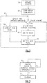
- a flowchart shown in Figure 2 improves upon this control.
- a counter is initialized, such as to zero.
- motor commutation is done in which the rotation of the permanent magnets on the rotor 28 is sensed by the several sensors 30.
- Sensors send pulses 46, as shown in Figure 1A . It is known to determine if a particular pulse is actually background noise or is an actual sensed pulse. As an example, this is disclosed in United States Reissue Patent 45,388 . Moreover, this patent discloses the basic position sensing as described. This sensing is incorporated into this application by reference.
- the count is comparted to an expected position count.
- the question is asked is the difference between the actual count and the expected position count greater than a predetermined value X. If not, then no action is taken. On the other hand, should the difference exceed the predetermined value X, then a calibration step 72 is taken.
- the value X may be selected to ensure there is not too much difference between actual and expected positions of the valve.
- Figure 1A also shows one embodiment of a calibration step.
- An item 80 on the component 42 is driven back against the stop 82. This then provides a zero position for the component 80 and the system can then move to drive the component 42 back towards a desired position, which becomes the expected position.
- Figure 1B shows another embodiment wherein a shaft 84, which may be either the shaft 32 or 38 from the Figure 1A system is provided with a permanent magnet 86.
- a sensor 88 which may be a Hall effect device, looks for the position of the magnet 86 and utilizes this position to again zero out or calibrate the location of the component 42 in the control 40. Then, the component 42 can be driven back toward a desired position.
Landscapes
- Engineering & Computer Science (AREA)
- General Engineering & Computer Science (AREA)
- Mechanical Engineering (AREA)
- Control Of Position Or Direction (AREA)
- Measurement Of Length, Angles, Or The Like Using Electric Or Magnetic Means (AREA)
Description
- This application relates to a system for identifying an actual position of a rotary device.
- Modern systems include any number of components which are driven by rotary motors. Many of these systems require precise positioning.
- Thus, it is known to develop position monitoring systems. As one example, in a brushless DC motor, it is known to provide sensors which sense rotation of the permanent magnets on a motor rotor. The motor rotor drives a shaft which, in turn, drives a component to a desired rotary position. In at least some systems, there is a gear speed change arrangement between a first shaft driven by the motor rotor and a second shaft which drives the component.
- In practice, there is the potential for a difference between a sensed position, based upon the rotation of the motor rotor, and an actual position of the component. This can occur due to backlash within the gears due to torsional spring features. In addition, the shafts have a spring like response to the torque from the motor to the component.
- There are also numerous other realities within an electromechanical system which can result in the sensed position being different from an actual position. All of these issues can result in the actual component position being different from a desired component position.
- Of course, this could be undesirable.
US 2005/152489 A1 describes a method of error-compensated counting of Hall states for position feedback.US 2007/194259 A1 describes a control system for a flow adjusting valve.US 2016/054351 A1 describes a method and apparatus for monitoring the speed and position of a rotating member. - An electromechanical system is defined in claim 1 and has a component to be positioned, a rotary permanent magnet motor for positioning the component, and sensors for determining an apparent position of the component based upon rotation of the permanent magnets. A control counts movement of the permanent magnets that pass the sensors in a desired direction and also in an undesired direction. The control reaches an actual position of the component based upon both directions of rotation. The control also compares the actual position to an expected position of the component and identifies a need to calibrate should a difference between the actual and expected positions differ by more than a determined amount. The control senses the rotation of said permanent magnets past said sensors in an undesired direction when said motor is stopped.
- A method is also disclosed and defined in claim 7.
- These and other features may be best understood from the following drawings and specification.
-
-
Figure 1A schematically shows an electromechanical system. -
Figure 1B shows an alternative system. -
Figure 2 is a flowchart. -
Figure 3 is a second flowchart. -
Figure 1A shows anelectromechanical system 20, which may be utilized on aspace craft 22. As can be appreciated,space craft 22 operates in an environment which may be exposed to unusually high amounts of radiation. This raises challenges with regard to control systems for utilization on thespace ship 22. -
System 20 includes abrushless DC motor 24 having astator 26 and arotor 28. As known, therotor 28 includes a plurality of permanent magnets. Sensors, which may beHall effect sensors 30 sense the passage of each of the magnets to calculate rotation of therotor 28. Signal pulses 46 fromsensors 30 are sent to acontrol 40, which calculates an apparent position of an output of thebrushless DC motor 24. - The
rotor 28 drives afirst shaft 32, which in this embodiment, drives agear 34. Gear 34 engages and drives agear 36 to provide a speed change between theinput shaft 32 and an output shaft 38. Output shaft 38 drives the rotational position of a component 42, which may be a valve. - In one embodiment, the valve controls supply of a
coolant 43 to anoutlet 45 for use of the coolant on aspace craft 22. - The
control 40 is driving themotor stator 26 to position the valve 42 at a desired position. While a valve 42 is disclosed, other components may come within the scope of this disclosure. - As can be appreciated, it may be desirable that the position of the valve 42 be known precisely to a
control 40. - Thus, it is known to take feedback of the rotation and utilize that feedback to identify an apparent position of the component 42.
- However, for the reasons set forth in the background of the invention, this feedback does not always provide an accurate indication of the actual position. As an example, when the
motor 28 stops, the forces in the electromechanical system can result in undesired reverse rotation. - A flowchart shown in
Figure 2 improves upon this control. Atstep 50, a counter is initialized, such as to zero. Then atstep 52, motor commutation is done in which the rotation of the permanent magnets on therotor 28 is sensed by theseveral sensors 30. - Sensors send pulses 46, as shown in
Figure 1A . It is known to determine if a particular pulse is actually background noise or is an actual sensed pulse. As an example, this is disclosed inUnited States Reissue Patent 45,388 . Moreover, this patent discloses the basic position sensing as described. This sensing is incorporated into this application by reference. - As shown in
Figure 2 , should a pulse be identified as background noise, it is deemed invalid and the method proceeds to wait for the next pulse at 58. However, should the pulse be deemed valid and in a correct or desired direction, then it is added to a count atstep 56. - As mentioned above, there are a number of spring forces within the
system 20 ofFigure 1 . When themotor 24 is stopped, it is possible for the system spring forces to result in rotation of the component 42 in an opposed direction from that desired. That is, the spring forces can relax and drive the component away from the desired positon. Atstep 60, should a pulse be sensed which is opposite to a desired direction, it is subtracted from the count. - Of course, the terms "add" and "subtract" would be dependent upon the desired direction. In some operations, rotation may be desired in say a counterclockwise direction such that the opposed movement would be clockwise. In other operations, it might be that the desired movement is clockwise, such that the "unwinding" would be counterclockwise. At any rate, the
steps - As shown in
Figure 3 atstep 70, the count is comparted to an expected position count. The question is asked is the difference between the actual count and the expected position count greater than a predetermined value X. If not, then no action is taken. On the other hand, should the difference exceed the predetermined value X, then a calibration step 72 is taken. - The value X may be selected to ensure there is not too much difference between actual and expected positions of the valve.
-
Figure 1A also shows one embodiment of a calibration step. An item 80 on the component 42 is driven back against the stop 82. This then provides a zero position for the component 80 and the system can then move to drive the component 42 back towards a desired position, which becomes the expected position. - It should be understood that the differences between the expected and actual position can build up over time and such a calibration step would remove that buildup, such that the actual position would become closer to the expected position.
-
Figure 1B shows another embodiment wherein a shaft 84, which may be either theshaft 32 or 38 from theFigure 1A system is provided with a permanent magnet 86. Asensor 88, which may be a Hall effect device, looks for the position of the magnet 86 and utilizes this position to again zero out or calibrate the location of the component 42 in thecontrol 40. Then, the component 42 can be driven back toward a desired position. - Although an embodiment of this invention has been disclosed, a worker of ordinary skill in this art would recognize that certain modifications would come within the scope of this invention. For that reason, the following claims should be studied to determine the true scope and content of this invention.
Claims (10)
- An electromechanical system (20) comprising:a component (42) to be positioned;a rotary permanent magnet motor (24) for positioning said component;sensors (30) for determining an apparent position of said component (42) based upon rotation of said permanent magnets; anda control (40) sensing movement of said permanent magnets past said sensors (30) in a desired direction, and also rotation of said permanent magnets past said sensors (30) in an undesired direction, and preparing a count of an actual position of said component (42) based upon both of said rotations, and wherein said control (40) senses said rotation of said permanent magnets past said sensors (30) in an undesired direction when said motor (24) stops, characterized by said control (40) also comparing said actual position to an expected position for said component (42) and identifying a need to calibrate should a difference between said actual and expected positions differ by more than a determined amount, wherein said permanent magnet motor (24) is configured to drive a first shaft (32) having a first gear (34), said first gear (34) driving at least a second gear (36) to, in turn, drive a second shaft (38) which moves said component (42) in a rotary direction, with said first and second gears (34, 36) changing a speed between said first and second shafts (32, 38) andwherein each of said first and second shafts (32, 38) and gear teeth between said first (34) and second (36) gears having a spring force which may result in rotation in said undesired direction when said motor (24) stops;
wherein if said calibration is deemed needed, a surface on said component (42) is driven against a stop (82) to provide a new expected position in said control for said component (42). - The electromechanical system (20) as set forth in claim 1, wherein said component (42) is a valve.
- The electromechanical system (20) as set forth in claim 1 or 2, wherein said sensors (30) are Hall effect sensors.
- The electromechanical system (20) as set forth in any preceding claim, wherein said component (42) is mounted on a space vehicle.
- The electromechanical system (20) as set forth in any preceding claim, wherein said control (40) is programmed to determine whether a pulse from each of said sensors (30) is either an invalid pulse, an actual pulse in said desired direction, or an actual pulse in said undesired direction.
- The electromechanical system as set forth in any preceding claim, wherein if said calibration is deemed needed, a sensor (30) senses a location of a feature, and the location of said feature being utilized to provide a new expected position in said control for said component (42), and
wherein said feature is a permanent magnet. - A method comprising the steps of:driving a rotary permanent magnet motor (24) for positioning a component;sensors (30) determining an apparent position of said component based upon rotation of said permanent magnets past said sensor (30); andsensing movement of said permanent magnets past said sensors (30) in a desired direction, and also rotation of said permanent magnets past said sensors in an undesired direction, and preparing a count of an actual position of said component (42) based upon both of said rotation directions, and comparing said actual position to an expected position of said component (42) and identifying a need to calibrate should a difference between said calculated and expected positions differ by more than a determined amount, and wherein said step of sensing said rotation of said permanent magnets past said sensors in said undesired direction occurs when said motor (24) stops; wherein said permanent magnet motor (24) drives a first shaft (32) having a first gear (34), said first gear (34) driving at least a second gear (36) to, in turn, drive a second shaft (38) which moves said component (42) in a rotary direction, with said first and second gears (34, 36) changing a speed between said first and second shafts (32, 38) andwherein each of said first and second shafts (32, 38) and gear teeth between said first (34) and second (36) gears having a spring force which may result in rotation in said undesired direction when said motor (24) stops;
wherein if said calibration is deemed needed, a surface on said component (42) is driven against a stop (82) to provide a new expected position in said control for said component (42). - The method as set forth in claim 7, wherein said component (42) is a valve.
- The method as set forth in claim 7 or 8, wherein said sensors (30) are Hall effect sensors, and/or wherein said component (42) is mounted on a space vehicle.
- The method as set forth in any of claims 7 to 9, wherein a control (40) determining if a pulse from each of said sensors (30) is either an invalid pulse, an actual pulse in said desired direction, or an actual pulse in said undesired direction.
Applications Claiming Priority (1)
| Application Number | Priority Date | Filing Date | Title |
|---|---|---|---|
| US15/455,174 US20180259091A1 (en) | 2017-03-10 | 2017-03-10 | Control valve positioning system |
Publications (2)
| Publication Number | Publication Date |
|---|---|
| EP3372882A1 EP3372882A1 (en) | 2018-09-12 |
| EP3372882B1 true EP3372882B1 (en) | 2021-07-07 |
Family
ID=61622375
Family Applications (1)
| Application Number | Title | Priority Date | Filing Date |
|---|---|---|---|
| EP18161008.0A Active EP3372882B1 (en) | 2017-03-10 | 2018-03-09 | Control valve positioning system |
Country Status (2)
| Country | Link |
|---|---|
| US (1) | US20180259091A1 (en) |
| EP (1) | EP3372882B1 (en) |
Families Citing this family (2)
| Publication number | Priority date | Publication date | Assignee | Title |
|---|---|---|---|---|
| CN111457142B (en) * | 2019-01-21 | 2022-04-22 | 杭州三花研究院有限公司 | Control method and control system |
| CN111076228A (en) * | 2019-12-12 | 2020-04-28 | 华帝股份有限公司 | Gear judgment method for kitchen range |
Family Cites Families (5)
| Publication number | Priority date | Publication date | Assignee | Title |
|---|---|---|---|---|
| US45388A (en) | 1864-12-13 | Improved coal-scuttle | ||
| US7049813B2 (en) * | 2004-01-09 | 2006-05-23 | Hr Textron Inc. | Motor state counting |
| US7374148B2 (en) * | 2006-02-22 | 2008-05-20 | I-Hua Huang | Control system for flow adjusting valve |
| US8294396B2 (en) * | 2009-07-13 | 2012-10-23 | Hamilton Sundstrand Space Systems International, Inc. | Compact FPGA-based digital motor controller |
| US9759737B2 (en) * | 2014-08-22 | 2017-09-12 | GM Global Technology Operations LLC | Method and apparatus for monitoring speed and position of a rotating member |
-
2017
- 2017-03-10 US US15/455,174 patent/US20180259091A1/en not_active Abandoned
-
2018
- 2018-03-09 EP EP18161008.0A patent/EP3372882B1/en active Active
Non-Patent Citations (1)
| Title |
|---|
| None * |
Also Published As
| Publication number | Publication date |
|---|---|
| US20180259091A1 (en) | 2018-09-13 |
| EP3372882A1 (en) | 2018-09-12 |
Similar Documents
| Publication | Publication Date | Title |
|---|---|---|
| JP6664995B2 (en) | Motor control method | |
| US7005814B2 (en) | Motor control apparatus having current supply phase correction | |
| US8412403B2 (en) | Method and device for increasing the precision of the position determination of a motor-driven closure element of a vehicle | |
| EP3372882A1 (en) | Control valve positioning system | |
| EP0786710B1 (en) | Positioning system with speed control mode and position control mode using speed profiling | |
| TWI660162B (en) | Motor controlling device and motor device using the same | |
| JP2023528432A5 (en) | ||
| JP6371010B1 (en) | Positioning control device for actuator with wave gear device by state observer combined type full closed control | |
| EP3072759B1 (en) | Brake force measurement techniques | |
| CN106404032B (en) | Method for controlling speed synchronization of main shaft of encoder | |
| US4757458A (en) | Zero point adjusting robot control method | |
| CN111457142B (en) | Control method and control system | |
| KR20210055930A (en) | DC Motor speed regulator and angular acceleration estimation system | |
| JP6874674B2 (en) | Shift range controller | |
| CN102778860A (en) | Control parameter adjustment method of position control device and control parameter adjustment method | |
| US20160072418A1 (en) | Method for precise position determination | |
| JP2006195566A (en) | Servo control device and control method thereof | |
| US20080129549A1 (en) | System and method for encoder failure detection | |
| US11945314B2 (en) | Method for operating a drive train, and drive train | |
| US10704661B2 (en) | Actuator device having cam and follower and controller configured to employ rate-based methodology to identify positioning of follower on cam at predetermined location | |
| EP1462916B1 (en) | Force-applying input device | |
| JP4140139B2 (en) | Load torque estimation method and torque control device | |
| JPH04336915A (en) | Tooth alignment method for nc device | |
| JP7552496B2 (en) | Control device for drive device and drive system | |
| EP3678290A1 (en) | Motor driving device |
Legal Events
| Date | Code | Title | Description |
|---|---|---|---|
| PUAI | Public reference made under article 153(3) epc to a published international application that has entered the european phase |
Free format text: ORIGINAL CODE: 0009012 |
|
| STAA | Information on the status of an ep patent application or granted ep patent |
Free format text: STATUS: THE APPLICATION HAS BEEN PUBLISHED |
|
| AK | Designated contracting states |
Kind code of ref document: A1 Designated state(s): AL AT BE BG CH CY CZ DE DK EE ES FI FR GB GR HR HU IE IS IT LI LT LU LV MC MK MT NL NO PL PT RO RS SE SI SK SM TR |
|
| AX | Request for extension of the european patent |
Extension state: BA ME |
|
| STAA | Information on the status of an ep patent application or granted ep patent |
Free format text: STATUS: REQUEST FOR EXAMINATION WAS MADE |
|
| 17P | Request for examination filed |
Effective date: 20190226 |
|
| RBV | Designated contracting states (corrected) |
Designated state(s): AL AT BE BG CH CY CZ DE DK EE ES FI FR GB GR HR HU IE IS IT LI LT LU LV MC MK MT NL NO PL PT RO RS SE SI SK SM TR |
|
| STAA | Information on the status of an ep patent application or granted ep patent |
Free format text: STATUS: EXAMINATION IS IN PROGRESS |
|
| 17Q | First examination report despatched |
Effective date: 20190703 |
|
| GRAP | Despatch of communication of intention to grant a patent |
Free format text: ORIGINAL CODE: EPIDOSNIGR1 |
|
| STAA | Information on the status of an ep patent application or granted ep patent |
Free format text: STATUS: GRANT OF PATENT IS INTENDED |
|
| INTG | Intention to grant announced |
Effective date: 20210211 |
|
| GRAS | Grant fee paid |
Free format text: ORIGINAL CODE: EPIDOSNIGR3 |
|
| GRAA | (expected) grant |
Free format text: ORIGINAL CODE: 0009210 |
|
| STAA | Information on the status of an ep patent application or granted ep patent |
Free format text: STATUS: THE PATENT HAS BEEN GRANTED |
|
| AK | Designated contracting states |
Kind code of ref document: B1 Designated state(s): AL AT BE BG CH CY CZ DE DK EE ES FI FR GB GR HR HU IE IS IT LI LT LU LV MC MK MT NL NO PL PT RO RS SE SI SK SM TR |
|
| REG | Reference to a national code |
Ref country code: GB Ref legal event code: FG4D |
|
| REG | Reference to a national code |
Ref country code: AT Ref legal event code: REF Ref document number: 1408914 Country of ref document: AT Kind code of ref document: T Effective date: 20210715 |
|
| REG | Reference to a national code |
Ref country code: DE Ref legal event code: R096 Ref document number: 602018019547 Country of ref document: DE |
|
| REG | Reference to a national code |
Ref country code: IE Ref legal event code: FG4D |
|
| REG | Reference to a national code |
Ref country code: LT Ref legal event code: MG9D |
|
| REG | Reference to a national code |
Ref country code: NL Ref legal event code: MP Effective date: 20210707 |
|
| REG | Reference to a national code |
Ref country code: AT Ref legal event code: MK05 Ref document number: 1408914 Country of ref document: AT Kind code of ref document: T Effective date: 20210707 |
|
| PG25 | Lapsed in a contracting state [announced via postgrant information from national office to epo] |
Ref country code: RS Free format text: LAPSE BECAUSE OF FAILURE TO SUBMIT A TRANSLATION OF THE DESCRIPTION OR TO PAY THE FEE WITHIN THE PRESCRIBED TIME-LIMIT Effective date: 20210707 Ref country code: SE Free format text: LAPSE BECAUSE OF FAILURE TO SUBMIT A TRANSLATION OF THE DESCRIPTION OR TO PAY THE FEE WITHIN THE PRESCRIBED TIME-LIMIT Effective date: 20210707 Ref country code: ES Free format text: LAPSE BECAUSE OF FAILURE TO SUBMIT A TRANSLATION OF THE DESCRIPTION OR TO PAY THE FEE WITHIN THE PRESCRIBED TIME-LIMIT Effective date: 20210707 Ref country code: FI Free format text: LAPSE BECAUSE OF FAILURE TO SUBMIT A TRANSLATION OF THE DESCRIPTION OR TO PAY THE FEE WITHIN THE PRESCRIBED TIME-LIMIT Effective date: 20210707 Ref country code: HR Free format text: LAPSE BECAUSE OF FAILURE TO SUBMIT A TRANSLATION OF THE DESCRIPTION OR TO PAY THE FEE WITHIN THE PRESCRIBED TIME-LIMIT Effective date: 20210707 Ref country code: PT Free format text: LAPSE BECAUSE OF FAILURE TO SUBMIT A TRANSLATION OF THE DESCRIPTION OR TO PAY THE FEE WITHIN THE PRESCRIBED TIME-LIMIT Effective date: 20211108 Ref country code: NL Free format text: LAPSE BECAUSE OF FAILURE TO SUBMIT A TRANSLATION OF THE DESCRIPTION OR TO PAY THE FEE WITHIN THE PRESCRIBED TIME-LIMIT Effective date: 20210707 Ref country code: NO Free format text: LAPSE BECAUSE OF FAILURE TO SUBMIT A TRANSLATION OF THE DESCRIPTION OR TO PAY THE FEE WITHIN THE PRESCRIBED TIME-LIMIT Effective date: 20211007 Ref country code: LT Free format text: LAPSE BECAUSE OF FAILURE TO SUBMIT A TRANSLATION OF THE DESCRIPTION OR TO PAY THE FEE WITHIN THE PRESCRIBED TIME-LIMIT Effective date: 20210707 Ref country code: BG Free format text: LAPSE BECAUSE OF FAILURE TO SUBMIT A TRANSLATION OF THE DESCRIPTION OR TO PAY THE FEE WITHIN THE PRESCRIBED TIME-LIMIT Effective date: 20211007 Ref country code: AT Free format text: LAPSE BECAUSE OF FAILURE TO SUBMIT A TRANSLATION OF THE DESCRIPTION OR TO PAY THE FEE WITHIN THE PRESCRIBED TIME-LIMIT Effective date: 20210707 |
|
| PG25 | Lapsed in a contracting state [announced via postgrant information from national office to epo] |
Ref country code: PL Free format text: LAPSE BECAUSE OF FAILURE TO SUBMIT A TRANSLATION OF THE DESCRIPTION OR TO PAY THE FEE WITHIN THE PRESCRIBED TIME-LIMIT Effective date: 20210707 Ref country code: LV Free format text: LAPSE BECAUSE OF FAILURE TO SUBMIT A TRANSLATION OF THE DESCRIPTION OR TO PAY THE FEE WITHIN THE PRESCRIBED TIME-LIMIT Effective date: 20210707 Ref country code: GR Free format text: LAPSE BECAUSE OF FAILURE TO SUBMIT A TRANSLATION OF THE DESCRIPTION OR TO PAY THE FEE WITHIN THE PRESCRIBED TIME-LIMIT Effective date: 20211008 |
|
| REG | Reference to a national code |
Ref country code: DE Ref legal event code: R097 Ref document number: 602018019547 Country of ref document: DE |
|
| PG25 | Lapsed in a contracting state [announced via postgrant information from national office to epo] |
Ref country code: DK Free format text: LAPSE BECAUSE OF FAILURE TO SUBMIT A TRANSLATION OF THE DESCRIPTION OR TO PAY THE FEE WITHIN THE PRESCRIBED TIME-LIMIT Effective date: 20210707 |
|
| PLBE | No opposition filed within time limit |
Free format text: ORIGINAL CODE: 0009261 |
|
| STAA | Information on the status of an ep patent application or granted ep patent |
Free format text: STATUS: NO OPPOSITION FILED WITHIN TIME LIMIT |
|
| PG25 | Lapsed in a contracting state [announced via postgrant information from national office to epo] |
Ref country code: SM Free format text: LAPSE BECAUSE OF FAILURE TO SUBMIT A TRANSLATION OF THE DESCRIPTION OR TO PAY THE FEE WITHIN THE PRESCRIBED TIME-LIMIT Effective date: 20210707 Ref country code: SK Free format text: LAPSE BECAUSE OF FAILURE TO SUBMIT A TRANSLATION OF THE DESCRIPTION OR TO PAY THE FEE WITHIN THE PRESCRIBED TIME-LIMIT Effective date: 20210707 Ref country code: RO Free format text: LAPSE BECAUSE OF FAILURE TO SUBMIT A TRANSLATION OF THE DESCRIPTION OR TO PAY THE FEE WITHIN THE PRESCRIBED TIME-LIMIT Effective date: 20210707 Ref country code: EE Free format text: LAPSE BECAUSE OF FAILURE TO SUBMIT A TRANSLATION OF THE DESCRIPTION OR TO PAY THE FEE WITHIN THE PRESCRIBED TIME-LIMIT Effective date: 20210707 Ref country code: CZ Free format text: LAPSE BECAUSE OF FAILURE TO SUBMIT A TRANSLATION OF THE DESCRIPTION OR TO PAY THE FEE WITHIN THE PRESCRIBED TIME-LIMIT Effective date: 20210707 Ref country code: AL Free format text: LAPSE BECAUSE OF FAILURE TO SUBMIT A TRANSLATION OF THE DESCRIPTION OR TO PAY THE FEE WITHIN THE PRESCRIBED TIME-LIMIT Effective date: 20210707 |
|
| 26N | No opposition filed |
Effective date: 20220408 |
|
| PG25 | Lapsed in a contracting state [announced via postgrant information from national office to epo] |
Ref country code: IT Free format text: LAPSE BECAUSE OF FAILURE TO SUBMIT A TRANSLATION OF THE DESCRIPTION OR TO PAY THE FEE WITHIN THE PRESCRIBED TIME-LIMIT Effective date: 20210707 |
|
| PG25 | Lapsed in a contracting state [announced via postgrant information from national office to epo] |
Ref country code: MC Free format text: LAPSE BECAUSE OF FAILURE TO SUBMIT A TRANSLATION OF THE DESCRIPTION OR TO PAY THE FEE WITHIN THE PRESCRIBED TIME-LIMIT Effective date: 20210707 |
|
| REG | Reference to a national code |
Ref country code: CH Ref legal event code: PL |
|
| REG | Reference to a national code |
Ref country code: BE Ref legal event code: MM Effective date: 20220331 |
|
| PG25 | Lapsed in a contracting state [announced via postgrant information from national office to epo] |
Ref country code: LU Free format text: LAPSE BECAUSE OF NON-PAYMENT OF DUE FEES Effective date: 20220309 Ref country code: LI Free format text: LAPSE BECAUSE OF NON-PAYMENT OF DUE FEES Effective date: 20220331 Ref country code: IE Free format text: LAPSE BECAUSE OF NON-PAYMENT OF DUE FEES Effective date: 20220309 Ref country code: CH Free format text: LAPSE BECAUSE OF NON-PAYMENT OF DUE FEES Effective date: 20220331 |
|
| PG25 | Lapsed in a contracting state [announced via postgrant information from national office to epo] |
Ref country code: BE Free format text: LAPSE BECAUSE OF NON-PAYMENT OF DUE FEES Effective date: 20220331 |
|
| P01 | Opt-out of the competence of the unified patent court (upc) registered |
Effective date: 20230522 |
|
| PG25 | Lapsed in a contracting state [announced via postgrant information from national office to epo] |
Ref country code: HU Free format text: LAPSE BECAUSE OF FAILURE TO SUBMIT A TRANSLATION OF THE DESCRIPTION OR TO PAY THE FEE WITHIN THE PRESCRIBED TIME-LIMIT; INVALID AB INITIO Effective date: 20180309 |
|
| PG25 | Lapsed in a contracting state [announced via postgrant information from national office to epo] |
Ref country code: MK Free format text: LAPSE BECAUSE OF FAILURE TO SUBMIT A TRANSLATION OF THE DESCRIPTION OR TO PAY THE FEE WITHIN THE PRESCRIBED TIME-LIMIT Effective date: 20210707 Ref country code: CY Free format text: LAPSE BECAUSE OF FAILURE TO SUBMIT A TRANSLATION OF THE DESCRIPTION OR TO PAY THE FEE WITHIN THE PRESCRIBED TIME-LIMIT Effective date: 20210707 |
|
| PG25 | Lapsed in a contracting state [announced via postgrant information from national office to epo] |
Ref country code: MT Free format text: LAPSE BECAUSE OF FAILURE TO SUBMIT A TRANSLATION OF THE DESCRIPTION OR TO PAY THE FEE WITHIN THE PRESCRIBED TIME-LIMIT Effective date: 20210707 |
|
| PG25 | Lapsed in a contracting state [announced via postgrant information from national office to epo] |
Ref country code: TR Free format text: LAPSE BECAUSE OF FAILURE TO SUBMIT A TRANSLATION OF THE DESCRIPTION OR TO PAY THE FEE WITHIN THE PRESCRIBED TIME-LIMIT Effective date: 20210707 |
|
| PGFP | Annual fee paid to national office [announced via postgrant information from national office to epo] |
Ref country code: GB Payment date: 20260219 Year of fee payment: 9 |
|
| PGFP | Annual fee paid to national office [announced via postgrant information from national office to epo] |
Ref country code: DE Payment date: 20260219 Year of fee payment: 9 |
|
| PGFP | Annual fee paid to national office [announced via postgrant information from national office to epo] |
Ref country code: FR Payment date: 20260219 Year of fee payment: 9 |