EP3372739A1 - Structure construction system - Google Patents
Structure construction system Download PDFInfo
- Publication number
- EP3372739A1 EP3372739A1 EP16861649.8A EP16861649A EP3372739A1 EP 3372739 A1 EP3372739 A1 EP 3372739A1 EP 16861649 A EP16861649 A EP 16861649A EP 3372739 A1 EP3372739 A1 EP 3372739A1
- Authority
- EP
- European Patent Office
- Prior art keywords
- profile
- rail
- cleat
- wing
- panels
- Prior art date
- Legal status (The legal status is an assumption and is not a legal conclusion. Google has not performed a legal analysis and makes no representation as to the accuracy of the status listed.)
- Withdrawn
Links
Images



Classifications
-
- E—FIXED CONSTRUCTIONS
- E04—BUILDING
- E04B—GENERAL BUILDING CONSTRUCTIONS; WALLS, e.g. PARTITIONS; ROOFS; FLOORS; CEILINGS; INSULATION OR OTHER PROTECTION OF BUILDINGS
- E04B1/00—Constructions in general; Structures which are not restricted either to walls, e.g. partitions, or floors or ceilings or roofs
- E04B1/18—Structures comprising elongated load-supporting parts, e.g. columns, girders, skeletons
- E04B1/24—Structures comprising elongated load-supporting parts, e.g. columns, girders, skeletons the supporting parts consisting of metal
-
- E—FIXED CONSTRUCTIONS
- E04—BUILDING
- E04B—GENERAL BUILDING CONSTRUCTIONS; WALLS, e.g. PARTITIONS; ROOFS; FLOORS; CEILINGS; INSULATION OR OTHER PROTECTION OF BUILDINGS
- E04B1/00—Constructions in general; Structures which are not restricted either to walls, e.g. partitions, or floors or ceilings or roofs
- E04B1/18—Structures comprising elongated load-supporting parts, e.g. columns, girders, skeletons
- E04B1/24—Structures comprising elongated load-supporting parts, e.g. columns, girders, skeletons the supporting parts consisting of metal
- E04B1/2403—Connection details of the elongated load-supporting parts
-
- E—FIXED CONSTRUCTIONS
- E04—BUILDING
- E04B—GENERAL BUILDING CONSTRUCTIONS; WALLS, e.g. PARTITIONS; ROOFS; FLOORS; CEILINGS; INSULATION OR OTHER PROTECTION OF BUILDINGS
- E04B7/00—Roofs; Roof construction with regard to insulation
- E04B7/02—Roofs; Roof construction with regard to insulation with plane sloping surfaces, e.g. saddle roofs
-
- E—FIXED CONSTRUCTIONS
- E04—BUILDING
- E04B—GENERAL BUILDING CONSTRUCTIONS; WALLS, e.g. PARTITIONS; ROOFS; FLOORS; CEILINGS; INSULATION OR OTHER PROTECTION OF BUILDINGS
- E04B7/00—Roofs; Roof construction with regard to insulation
- E04B7/02—Roofs; Roof construction with regard to insulation with plane sloping surfaces, e.g. saddle roofs
- E04B7/04—Roofs; Roof construction with regard to insulation with plane sloping surfaces, e.g. saddle roofs supported by horizontal beams or the equivalent resting on the walls
- E04B7/045—Roofs; Roof construction with regard to insulation with plane sloping surfaces, e.g. saddle roofs supported by horizontal beams or the equivalent resting on the walls with connectors made of sheet metal for connecting the roof structure to the supporting wall
-
- E—FIXED CONSTRUCTIONS
- E04—BUILDING
- E04H—BUILDINGS OR LIKE STRUCTURES FOR PARTICULAR PURPOSES; SWIMMING OR SPLASH BATHS OR POOLS; MASTS; FENCING; TENTS OR CANOPIES, IN GENERAL
- E04H5/00—Buildings or groups of buildings for industrial or agricultural purposes
- E04H5/08—Buildings or groups of buildings for agricultural purposes
-
- E—FIXED CONSTRUCTIONS
- E04—BUILDING
- E04B—GENERAL BUILDING CONSTRUCTIONS; WALLS, e.g. PARTITIONS; ROOFS; FLOORS; CEILINGS; INSULATION OR OTHER PROTECTION OF BUILDINGS
- E04B1/00—Constructions in general; Structures which are not restricted either to walls, e.g. partitions, or floors or ceilings or roofs
- E04B1/18—Structures comprising elongated load-supporting parts, e.g. columns, girders, skeletons
- E04B1/24—Structures comprising elongated load-supporting parts, e.g. columns, girders, skeletons the supporting parts consisting of metal
- E04B1/2403—Connection details of the elongated load-supporting parts
- E04B2001/2415—Brackets, gussets, joining plates
-
- E—FIXED CONSTRUCTIONS
- E04—BUILDING
- E04B—GENERAL BUILDING CONSTRUCTIONS; WALLS, e.g. PARTITIONS; ROOFS; FLOORS; CEILINGS; INSULATION OR OTHER PROTECTION OF BUILDINGS
- E04B1/00—Constructions in general; Structures which are not restricted either to walls, e.g. partitions, or floors or ceilings or roofs
- E04B1/18—Structures comprising elongated load-supporting parts, e.g. columns, girders, skeletons
- E04B1/24—Structures comprising elongated load-supporting parts, e.g. columns, girders, skeletons the supporting parts consisting of metal
- E04B1/2403—Connection details of the elongated load-supporting parts
- E04B2001/2448—Connections between open section profiles
-
- E—FIXED CONSTRUCTIONS
- E04—BUILDING
- E04B—GENERAL BUILDING CONSTRUCTIONS; WALLS, e.g. PARTITIONS; ROOFS; FLOORS; CEILINGS; INSULATION OR OTHER PROTECTION OF BUILDINGS
- E04B1/00—Constructions in general; Structures which are not restricted either to walls, e.g. partitions, or floors or ceilings or roofs
- E04B1/18—Structures comprising elongated load-supporting parts, e.g. columns, girders, skeletons
- E04B1/24—Structures comprising elongated load-supporting parts, e.g. columns, girders, skeletons the supporting parts consisting of metal
- E04B1/2403—Connection details of the elongated load-supporting parts
- E04B2001/2463—Connections to foundations
-
- E—FIXED CONSTRUCTIONS
- E04—BUILDING
- E04B—GENERAL BUILDING CONSTRUCTIONS; WALLS, e.g. PARTITIONS; ROOFS; FLOORS; CEILINGS; INSULATION OR OTHER PROTECTION OF BUILDINGS
- E04B1/00—Constructions in general; Structures which are not restricted either to walls, e.g. partitions, or floors or ceilings or roofs
- E04B1/18—Structures comprising elongated load-supporting parts, e.g. columns, girders, skeletons
- E04B1/24—Structures comprising elongated load-supporting parts, e.g. columns, girders, skeletons the supporting parts consisting of metal
- E04B2001/2481—Details of wall panels
Definitions
- fan covers have been provided in the construction system assembly to avoid the entry of air and cold, light from the outside and the continuity of the luz of the exterior and the thermal bridge, covers which are folding to perform an opening when the fans are operating, and establish a closure when they are inoperative as if it was a window, being obtained based on stainless steel sheet profiles with sandwich panel and rubber draught excluder of those used in cold storage rooms.
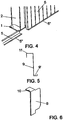
- a metal profile (5) as represented figure 2 , of Z-configuration, so that the upper and inner side wing (5') of that metal profile (5) is inserted in the groove (3) corresponding to the support plate (1), whilst the lower channel or external lower side wing (5") defined by said profile (5) forms the means of support and positioning for the corresponding facade panel (6), all so that the inner wing (5') is inserted in the groove (3) of the support plate (1) and the channel of the profile (5) is outward oriented, for the assembly of said facade panel (6), securing this by means of corresponding screws on the outer side of the profile (5) of the channel where the facade panel (6) precisely rests, these details being clearly shown in figure 4 .
- cleat (8) Another element which participates in the construction system of the invention is a part called cleat (8), represented in figure 6 , which is secured on the cladding rail (9), so that the cleat (8) has an upper wing (10) that rests on the upper plane (11) of the cladding rail (9), welding said cleat (8) to the corresponding rafter (12).
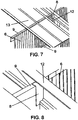
- Figures 7 and 8 precisely show the facade panel (6), the rail or rails (9), the cleat (8) and the roof panel (13), so that the cleat (8) forms the anchoring of one of the roof rails (9), also called cladding rail whereon is screwed (10) of the cleat (8) to remain at the height of the face of the rafter (12), so that the roof panel (13) closes against the cladding rail (9).
Landscapes
- Engineering & Computer Science (AREA)
- Architecture (AREA)
- Civil Engineering (AREA)
- Structural Engineering (AREA)
- Physics & Mathematics (AREA)
- Electromagnetism (AREA)
- Building Environments (AREA)
- Finishing Walls (AREA)
Abstract
Description
- The present invention relates to a structure construction system, preferably and fundamentally intended for its application in the construction of structures for industrial units, such as those intended for farms and such like.
- The object of the invention is to provide a construction system which allows greater speed in the assembly of the different parts that participate in the structure, and a better finish and more effective thermal sealing, among other advantages that will be stated throughout the present description.
- Although numerous construction systems are known for executing structures for industrial units and such like, including rafters, rails, claddings both of the facade and roof, and include false ceilings, however, in this type of systems there is a common denominator, which is the complexity of assembly and consequent increase in the final cost of the structure, in addition to finishes which are not usually the most appropriate.
- In any case, the inventor is unaware of structure construction systems with the characteristics described in the present specification.
- The construction system claimed is based on using a support plate for each one of the columns of the structure, of preferably quadrangular configuration and in proximity to one of the edges and in correspondence with two opposite edges, it has a pair of grooves that define among the edge mentioned first and the grooves a portion of plate with an orifice, the function of which will be stated later.
- In the construction system there also participates a guide and support profile for the corresponding facade panel, with Z-profile with an upper rectangular groove, the external wing of which is positioned on one of the grooves of the base plate, whilst the other groove, of greater amplitude and which is positioned inwards, defines the support, guiding and seating of the lower part of the corresponding facade panel or facade panels which are coupled together by dovetailing.
- Through the upper wing of the Z-profile is secured the base plate by screwing, whilst through the external wing of the lower support groove of the panels it is secured by screwing to said panels, so that said Z-panel is secured on the one hand to the base plate by screwing and on the other it serves as a means of securing for the facade panels.
- This achieves a perfect support of the lower part of the facade panels and then in a straight line thereof in their coupling by dovetailing and located in the lower channel of said Z-profile.
- Another part that participates in the construction system of the invention is the profile that constitutes the cladding rail of the upper part of the facade panels, also Z-profile, of greater height, defining an inverted upper groove for positioning the upper part of the facade panels, and a lower groove and of smaller amplitude which constitutes the means of securing for the false ceiling.
- The system is complemented with another part that consists of a cleat which, on the one hand, fulfils the function of anchoring for one of the rails of the roof structure, called cladding rail and which is secured to the cleat by screwing, and the other forming a means of sealing of the cavity existing between the facade panel and the corresponding rafter, thus obtaining a perfect finish.
- The cleat is an angular part, with an upper wing of screwing to the upper cladding rail, and a side wing which is secured by welding to the corresponding rafter, all so that the corresponding roof panel will close against said cladding rail.
- The cleats that participate in the system are welded to the rafters and the rails are screwed so that they form spans of facade panels between rafters, placing the rail to seal the panels, by screwing to the cleat.
- As regards the cladding rail, due to its special Z-configuration, it offers a series of advantages and features that are listed below.
- It seals the facade panels by the upper part, which means that said panels are sealed by their four sides improving the thermal insulation and they avoid the formation of infestations inside the panel.
- It maintains a perfect line in the upper part and gives rigidity to the system by joining all the panels.
- The upper part is aligned with the roof panel, perfectly adjusting thereto, subsequent sealing not being necessary nor the user of additional foams or profiles.
- The side and inner tab that establishes the grooved form of the rail, constitutes a means for the screwing of the corresponding false ceiling of the construction.
- Another part to bear in mind is a logotype sheet which is welded to the end of the rafters that form the porticoes, fulfilling a dual function since, on the one hand it incorporates a personalized logo of the name of the proprietor company and, on the other, it serves as anchoring of the perimeter cladding rail of the roof.
- It is also necessary to highlight the fact that fan covers have been provided in the construction system assembly to avoid the entry of air and cold, light from the outside and the continuity of the luz of the exterior and the thermal bridge, covers which are folding to perform an opening when the fans are operating, and establish a closure when they are inoperative as if it was a window, being obtained based on stainless steel sheet profiles with sandwich panel and rubber draught excluder of those used in cold storage rooms.
- Finally, we should state that the construction system is complemented with a protection for doors and hatches, based on stainless steel and rubber draught excluder to avoid the entry of air through the lower part, in addition to preventing contact with the chamber and sawdust and other components that lie on the floor of farms, thus avoiding corrosion.
- To complement the description being made and in order to aid towards a better understanding of the characteristics of the invention, in accordance with a preferred example of practical embodiment thereof, a set of drawings is attached as an integral part of said description wherein, with illustrative and non-limiting character, the following has been represented:
-
Figure 1 .- Shows a representation corresponding to a plan view of the support plate of the column that participates in the construction system object of the present invention. -
Figure 2 .- Shows a cross-section of the metal profile for support of the facade panels. -
Figure 3 .- Shows a perspective view of the form of assembly of the profile represented in the previous figure with respect to the base support plate of the column. -
Figure 4 .- Shows a perspective view of the form of assembly of the facade panel on the profiles secured to the base plate. -
Figure 5 .- Shows a cross-section of the profile corresponding to the cladding rail of the upper part. -
Figure 6 .- Shows a perspective view of the form of the cleat that participates in the system of the invention. -
Figure 7 .- Shows the layout of the facade, rail, cleat and roof panel cladding. -
Figure 8 . - Shows a detail of the form in which the cleat that participates in the system is mounted. -
Figure 9 .- Shows a sectional view by a vertical plane of the form of assembly of the cleat with respect to the cladding rail, including the facade panel mounted. -
Figure 10 .- Shows a perspective view of the meeting point between roof, rafter and facade panel, all according to an external view. -
Figure 11 .- Shows a perspective view of the logotype sheet used in the construction system of the invention. -
Figure 12 .- Shows a perspective detail of the form in which the logotype sheet of the previous figure is fixed. -
Figure 13 .- Shows a perspective view of the cover of the fans in open position. -
Figure 14 .- Shows a perspective view of the cover of the previous figure in closed position. - As can be seen in the indicated figures, the structure construction system object of the invention is based on a plate (1) which is quadrangular or rectangular, to support the corresponding column (2), as represented in
figure 3 , a plate (1) which has a pair of grooves (3) on two opposite sides and in proximity to a third side common to the previous, so that the portions or sectors that are determined between the grooves and the edge of the common side has an orifice (4), the function of which shall be later stated. - In the system there also participates a metal profile (5) as represented
figure 2 , of Z-configuration, so that the upper and inner side wing (5') of that metal profile (5) is inserted in the groove (3) corresponding to the support plate (1), whilst the lower channel or external lower side wing (5") defined by said profile (5) forms the means of support and positioning for the corresponding facade panel (6), all so that the inner wing (5') is inserted in the groove (3) of the support plate (1) and the channel of the profile (5) is outward oriented, for the assembly of said facade panel (6), securing this by means of corresponding screws on the outer side of the profile (5) of the channel where the facade panel (6) precisely rests, these details being clearly shown infigure 4 . - Logically, the external wing (5") wherefrom is secured by means of screws the lower part of the facade panel (6) is disposed outward, being the only visible wing of the profile as represented in
figure 4 , since the rest is hidden, either behind and to the side of the facade panel (6) or concealed by the lower edge or part of said panel. -
Figure 3 shows an end of the profile (5) secured by a screw (7) threaded in the orifice (4) provided on one side of the respective groove (3). - Furthermore,
figure 4 shows a facade panel (6) on the corresponding metal profile (5) and another metal profile (5) in assembled positioned on the base plate (1) but in the position to receive the facade panel (6), not represented in said figure. - The facade panel (6) is formed by means of dovetailing of a series of correlative panels, which are perfectly aligned in the channel defined by the metal profiles (5).
- In this way, the panels are installed continuously without cuts, nooks or slots with strange shapes which in the current systems prevent easy cleaning and the viewing of the animals inside in the case of farms.
- In other words, based on the construction system of the invention, the adjustment of the facade panels (6) with those of the roof, as shall be detailed below, is millimetric, offering continuity in the thermal insulation and favouring energy saving, avoiding the use of low quality foams and sealants.
- The upper edge of the facade panels (6) fits in the corresponding cladding rail (9), represented in section in
figure 5 , a rail which has a Z-configuration, resting said upper edge of the facade panels (6) on the lower surface of the plane (11) which is defined in the cladding rail (9). - Another element which participates in the construction system of the invention is a part called cleat (8), represented in
figure 6 , which is secured on the cladding rail (9), so that the cleat (8) has an upper wing (10) that rests on the upper plane (11) of the cladding rail (9), welding said cleat (8) to the corresponding rafter (12). - The superposition of the wing (10) of the cleat (8) on the upper plane (11) of the cladding rail (9) makes it possible to secure it by means of screws through an orifice of said wing (10) which thread in the upper plane (11) of the cladding rail (9).
- This cladding rail (9) has the purpose of sealing the facade panels (6) in their upper part, these seals being on the four sides and thus improving thermal insulation, avoiding the proliferation of infestations inside the panel.
- Furthermore, it mains a perfectly straight line in the upper part and gives rigidity to the system on joining together all of the panels, with the upper part being aligned with the roof panel (13).
-
Figures 7 and 8 precisely show the facade panel (6), the rail or rails (9), the cleat (8) and the roof panel (13), so that the cleat (8) forms the anchoring of one of the roof rails (9), also called cladding rail whereon is screwed (10) of the cleat (8) to remain at the height of the face of the rafter (12), so that the roof panel (13) closes against the cladding rail (9). - In
figure 9 it can be seen, according to a profile view, how the facade panel (6) is internally disposed between the cleat (8), which emerges perpendicularly from the rafter (12) whereto it is welded and the roof rail (9), with the upper part resting and duly fixed by screwing the corresponding roof (13). -
Figure 10 shows the meeting point between the cladding roof panel (13), the facade panel (6) and the corresponding rafter (12), observing how the cleat (8) establishes a sealing of the cavity between the panel and the rafter. - In short, it is a construction system wherein the facade panels (6) are perfectly aligned without discontinuities of any type, whilst the cladding rail or rails grip said panels (6) in their upper part, sealing them, at the same time as they are screwed to the panel.
- For its part, the lower part (9') of the profile of the cladding rail forms the means of securing by screwing of the corresponding false ceiling, so that the cladding rail (9) is in line with the lower face of the rafters, with the false ceiling being screwed, as stated, to said lower part (9').
- The rafters (12) are finished at their end in a sheet (15) which is welded thereto, as shown in
figure 11 , rafters which form the porticoes and where said sheet fulfils a dual function, incorporating on the one side a logo which includes the name of the proprietor company and, on the other, forms an anchoring element of the perimeter rail (9) of the cladding. - Optionally, the construction system is complemented with covers (16) to avoid the entry of air and light from the outside and the continuity of the thermal bridge, covers which are provided in accordance with the fans (17) of the installation, being manufactured in sandwich-type stainless steel sheet with rubber draught excluders for cold storage rooms (18) to occupy a separate position or a closed position as represented in
figures 13 and 14 .
Claims (3)
- Structures construction system, provided to form industrial units, preferably for farms, characterized in that it comprises a lower support plate (1) for the corresponding column (2), a plate which has on two opposite sides and in proximity to a third side, side grooves (3) wherebetween an orifice (4) is established, for the securing of the upper wing corresponding to a metal Z-profile (5) with its inner upper wing (5') housed in the grooves (3) of the support plate (1), whilst the lower part and of greater amplitude of said metal profile (5) defines a support and alignment channel of the facade panels (6), these being screwed through said external lower side wing (5") of the profile; having provided a profile acting as cladding rail (9) formed by a Z-profile on which lower surface of the upper plane (11) fits the upper edge of the facade panels (6), cladding rail which, in combination with a part or cleat (8) which is welded to the rafters (12) of the roof, establishes a means of sealing of the upper part of the facade panels (6), with the cleat (8) having an upper wing (10) of support for the upper plane (11) of the profile corresponding to the cladding rail (9), a rail the upper and horizontal section of which is secured by means of screwing to the upper wing (10) of the cleat (8), whilst the lower part (9') defines a mounting and securing channel of the corresponding false ceiling of the installation, at the same time as the roof panel is screwed to the upper plane (11) of the cladding rail.
- Structures construction system, according to claim 1, characterized in that it includes a sheet (15) securable by means of welding at the ends of the rafters (12) which form the upper porticoes of the construction, so this sheet provides a means of anchoring for the corresponding perimeter rail of the roof where the roof panel (13) is screwed.
- Structure construction system, according to claim 1, wherein in correspondence with the fans that may be present in the installation, closure covers (16) are defined, materialized from stainless steel profiles, which form a frame to house sandwich-type panels which form the cover and with rubber draught excluders of cold storage room. Said covers are mounted through tilt arms (18) to allow a position of separate opening with respect to the fan, or a closure position by way of a window.
Applications Claiming Priority (2)
| Application Number | Priority Date | Filing Date | Title |
|---|---|---|---|
| ES201531564A ES2569429B1 (en) | 2015-11-02 | 2015-11-02 | Structural Construction System |
| PCT/ES2016/070759 WO2017077150A1 (en) | 2015-11-02 | 2016-10-26 | Structure construction system |
Publications (2)
| Publication Number | Publication Date |
|---|---|
| EP3372739A1 true EP3372739A1 (en) | 2018-09-12 |
| EP3372739A4 EP3372739A4 (en) | 2019-05-29 |
Family
ID=55867730
Family Applications (1)
| Application Number | Title | Priority Date | Filing Date |
|---|---|---|---|
| EP16861649.8A Withdrawn EP3372739A4 (en) | 2015-11-02 | 2016-10-26 | Structure construction system |
Country Status (4)
| Country | Link |
|---|---|
| EP (1) | EP3372739A4 (en) |
| ES (1) | ES2569429B1 (en) |
| MA (1) | MA43182A (en) |
| WO (1) | WO2017077150A1 (en) |
Family Cites Families (5)
| Publication number | Priority date | Publication date | Assignee | Title |
|---|---|---|---|---|
| US2300113A (en) * | 1939-04-01 | 1942-10-27 | Herbert A Faber | Building construction |
| SE436372B (en) * | 1982-12-27 | 1984-12-03 | David Alfred Hellgren | WALL PARTS INCLUDED IN AN EXTERNAL WALL IN A HOUSE |
| US6240682B1 (en) * | 1998-10-19 | 2001-06-05 | V.P. Buildings, Inc. | Roof bracket |
| CA2365717C (en) * | 2000-12-22 | 2009-09-22 | Biomedy Limited | Constructional elements |
| EP2625345A4 (en) * | 2010-10-08 | 2014-08-06 | Pearls Miihome Ip Pty Ltd | A building |
-
2015
- 2015-11-02 ES ES201531564A patent/ES2569429B1/en not_active Expired - Fee Related
-
2016
- 2016-10-26 EP EP16861649.8A patent/EP3372739A4/en not_active Withdrawn
- 2016-10-26 MA MA043182A patent/MA43182A/en unknown
- 2016-10-26 WO PCT/ES2016/070759 patent/WO2017077150A1/en not_active Ceased
Also Published As
| Publication number | Publication date |
|---|---|
| EP3372739A4 (en) | 2019-05-29 |
| ES2569429A1 (en) | 2016-05-10 |
| WO2017077150A1 (en) | 2017-05-11 |
| ES2569429B1 (en) | 2016-11-10 |
| MA43182A (en) | 2018-09-12 |
Similar Documents
| Publication | Publication Date | Title |
|---|---|---|
| US4057941A (en) | Modular green house construction | |
| CA2804654C (en) | Demountable wall system | |
| US9140008B2 (en) | Multi-layered cladding frame system | |
| US4151691A (en) | Wall partition assembly | |
| US8661734B2 (en) | Window assembly with a sliding member and a security member having a ventilation portion | |
| US9027295B2 (en) | Sliding door and pivoting door for demountable wall system | |
| US9255439B2 (en) | Vision lite and screw boss channel | |
| GB2492380A (en) | Thermal shield for window | |
| KR101486064B1 (en) | Insulation and vent assembly for windows and doors | |
| EP3372739A1 (en) | Structure construction system | |
| JPH0913796A (en) | Renovated window | |
| JP6606373B2 (en) | Child door unit and construction method of child door unit | |
| KR102018426B1 (en) | Dividing window being easy to adjust and assemble | |
| JP7535916B2 (en) | Closing structure for architectural louvers | |
| JP6363374B2 (en) | sash | |
| JP5841927B2 (en) | Joinery | |
| KR102018425B1 (en) | Window fram dividing bar set being easy to install and adjust position and dividing window prepared therefrom | |
| GB2412139A (en) | Fire resistant glazing | |
| JP5213942B2 (en) | Panel fixing structure | |
| EP3467246A1 (en) | A mounting assembly for mounting sliding doors to a substrate | |
| JPS5853424Y2 (en) | Double sash with transom | |
| JP6996691B2 (en) | Seal structure between joinery frame and outer wall material | |
| JPH0442469Y2 (en) | ||
| JPH11190170A (en) | Band window sash | |
| JP2025112189A (en) | Fixture |
Legal Events
| Date | Code | Title | Description |
|---|---|---|---|
| STAA | Information on the status of an ep patent application or granted ep patent |
Free format text: STATUS: THE INTERNATIONAL PUBLICATION HAS BEEN MADE |
|
| PUAI | Public reference made under article 153(3) epc to a published international application that has entered the european phase |
Free format text: ORIGINAL CODE: 0009012 |
|
| STAA | Information on the status of an ep patent application or granted ep patent |
Free format text: STATUS: REQUEST FOR EXAMINATION WAS MADE |
|
| 17P | Request for examination filed |
Effective date: 20171113 |
|
| AK | Designated contracting states |
Kind code of ref document: A1 Designated state(s): AL AT BE BG CH CY CZ DE DK EE ES FI FR GB GR HR HU IE IS IT LI LT LU LV MC MK MT NL NO PL PT RO RS SE SI SK SM TR |
|
| AX | Request for extension of the european patent |
Extension state: BA ME |
|
| DAX | Request for extension of the european patent (deleted) | ||
| RAV | Requested validation state of the european patent: fee paid |
Extension state: MA Effective date: 20171031 |
|
| A4 | Supplementary search report drawn up and despatched |
Effective date: 20190430 |
|
| RIC1 | Information provided on ipc code assigned before grant |
Ipc: E04B 7/04 20060101ALI20190424BHEP Ipc: E04B 1/24 20060101AFI20190424BHEP Ipc: E04H 5/08 20060101ALI20190424BHEP |
|
| STAA | Information on the status of an ep patent application or granted ep patent |
Free format text: STATUS: EXAMINATION IS IN PROGRESS |
|
| 17Q | First examination report despatched |
Effective date: 20220311 |
|
| STAA | Information on the status of an ep patent application or granted ep patent |
Free format text: STATUS: THE APPLICATION IS DEEMED TO BE WITHDRAWN |
|
| 18D | Application deemed to be withdrawn |
Effective date: 20240501 |