EP3372718B1 - Herstellungsverfahren einer vernadelten faserstruktur - Google Patents
Herstellungsverfahren einer vernadelten faserstruktur Download PDFInfo
- Publication number
- EP3372718B1 EP3372718B1 EP18159859.0A EP18159859A EP3372718B1 EP 3372718 B1 EP3372718 B1 EP 3372718B1 EP 18159859 A EP18159859 A EP 18159859A EP 3372718 B1 EP3372718 B1 EP 3372718B1
- Authority
- EP
- European Patent Office
- Prior art keywords
- needling
- support
- head
- layer
- relative
- Prior art date
- Legal status (The legal status is an assumption and is not a legal conclusion. Google has not performed a legal analysis and makes no representation as to the accuracy of the status listed.)
- Active
Links
Images



Classifications
-
- D—TEXTILES; PAPER
- D04—BRAIDING; LACE-MAKING; KNITTING; TRIMMINGS; NON-WOVEN FABRICS
- D04H—MAKING TEXTILE FABRICS, e.g. FROM FIBRES OR FILAMENTARY MATERIAL; FABRICS MADE BY SUCH PROCESSES OR APPARATUS, e.g. FELTS, NON-WOVEN FABRICS; COTTON-WOOL; WADDING ; NON-WOVEN FABRICS FROM STAPLE FIBRES, FILAMENTS OR YARNS, BONDED WITH AT LEAST ONE WEB-LIKE MATERIAL DURING THEIR CONSOLIDATION
- D04H1/00—Non-woven fabrics formed wholly or mainly of staple fibres or like relatively short fibres
- D04H1/40—Non-woven fabrics formed wholly or mainly of staple fibres or like relatively short fibres from fleeces or layers composed of fibres without existing or potential cohesive properties
- D04H1/44—Non-woven fabrics formed wholly or mainly of staple fibres or like relatively short fibres from fleeces or layers composed of fibres without existing or potential cohesive properties the fleeces or layers being consolidated by mechanical means, e.g. by rolling
- D04H1/46—Non-woven fabrics formed wholly or mainly of staple fibres or like relatively short fibres from fleeces or layers composed of fibres without existing or potential cohesive properties the fleeces or layers being consolidated by mechanical means, e.g. by rolling by needling or like operations to cause entanglement of fibres
-
- D—TEXTILES; PAPER
- D04—BRAIDING; LACE-MAKING; KNITTING; TRIMMINGS; NON-WOVEN FABRICS
- D04H—MAKING TEXTILE FABRICS, e.g. FROM FIBRES OR FILAMENTARY MATERIAL; FABRICS MADE BY SUCH PROCESSES OR APPARATUS, e.g. FELTS, NON-WOVEN FABRICS; COTTON-WOOL; WADDING ; NON-WOVEN FABRICS FROM STAPLE FIBRES, FILAMENTS OR YARNS, BONDED WITH AT LEAST ONE WEB-LIKE MATERIAL DURING THEIR CONSOLIDATION
- D04H18/00—Needling machines
- D04H18/02—Needling machines with needles
-
- D—TEXTILES; PAPER
- D04—BRAIDING; LACE-MAKING; KNITTING; TRIMMINGS; NON-WOVEN FABRICS
- D04H—MAKING TEXTILE FABRICS, e.g. FROM FIBRES OR FILAMENTARY MATERIAL; FABRICS MADE BY SUCH PROCESSES OR APPARATUS, e.g. FELTS, NON-WOVEN FABRICS; COTTON-WOOL; WADDING ; NON-WOVEN FABRICS FROM STAPLE FIBRES, FILAMENTS OR YARNS, BONDED WITH AT LEAST ONE WEB-LIKE MATERIAL DURING THEIR CONSOLIDATION
- D04H3/00—Non-woven fabrics formed wholly or mainly of yarns or like filamentary material of substantial length
- D04H3/08—Non-woven fabrics formed wholly or mainly of yarns or like filamentary material of substantial length characterised by the method of strengthening or consolidating
- D04H3/10—Non-woven fabrics formed wholly or mainly of yarns or like filamentary material of substantial length characterised by the method of strengthening or consolidating with bonds between yarns or filaments made mechanically
- D04H3/105—Non-woven fabrics formed wholly or mainly of yarns or like filamentary material of substantial length characterised by the method of strengthening or consolidating with bonds between yarns or filaments made mechanically by needling
Definitions
- the present invention relates to the general field of methods of manufacturing needled fibrous structures, which can be used for the manufacture of parts made of composite material.
- needling machines which can be used to make needled textile structures.
- a first machine of the planar type the needling of fibrous layers stacked on a table is carried out, the table moving in horizontal translation in front of a vertically movable needling head.
- a second machine of the circular type the needling of a continuous fibrous layer wound around a rotary mandrel is carried out.
- the mandrel has a surface of revolution around which the layer is wound, the layer being located opposite a movable needling head in a direction perpendicular to this surface.
- the needlepunched fibrous structures obtained have zones of weakness. These fragile zones are mainly due to recurrent needling on the same zone between two consecutive fibrous layers.
- the needling head moves along the fibrous layer to be needled (for example by translation of the table or rotation of the mandrel)
- the successive passages of the head between two layers can produce holes aligned in the direction the layer scrolling (phenomenon called "lineage").
- the method according to the invention makes it possible to reduce the risk that the needles of the needling head come to needling the same place twice between two successive fibrous layers.
- the step of relative displacement of the support relative to the needling head, corresponding to a relative offset of these elements relative to each other, makes it possible to prevent the needles from striking generally at the same place between two successive layers.
- the method according to the invention makes it possible to prevent the formation of needled hole lines (“lineage” phenomenon) between two successive layers and to reduce the brittleness problems caused by the latter.
- the composite material parts resulting from the subsequent densification of a needled fibrous structure obtained by a method according to the invention thus exhibit improved mechanical strength.
- the support can be a table or a rotary mandrel around an axis of rotation.
- the needling head can, during a needling step, move in translation perpendicular to the surface of the table with a vertical movement alternative.
- the table can move in translation in front of the needling head in order to needle a fibrous layer of larger size than that of the needling head.
- the needling head can, during a needling step, move perpendicular to the surface of the mandrel with an alternating vertical movement, that is to say in a radial direction by relative to the axis of rotation of the mandrel.
- the support can advantageously be a table, movable or not in translation in front of the needling head.
- the relative displacement of the support relative to the needling head may include a relative rotation of the support relative to the needling head.
- the relative rotation of the support relative to the needling head can be a rotation of the support along an axis perpendicular to a surface of the support.
- the support can rotate through a non-zero angle less than or equal to 5 °, for example less than or equal to 2 °.
- a range of angles reduced in this way makes it possible to avoid the presence of so-called “dead” zones where the fibrous layers are not needled.
- the support can advantageously be a rotary mandrel around an axis of rotation and on which a fibrous structure can be wound, a layer of fibrous structure making, for example, a turn around the mandrel.
- the relative displacement of the support relative to the needling head may include a relative translation of the support relative to the needling head.
- the support of the needling machine can be rotatable about an axis of rotation, the relative displacement of the support relative to the needling head then being a relative translation of the needling head relative to the support in a direction parallel to the axis of rotation of the support.
- the needling head or the support can be translated by a non-zero distance less than or equal to 30 mm, for example less than or equal to 15 mm, in particular in order to reduce the presence of dead zones in the needled layers.
- a planar type needling machine 100 which comprises a needling head 110 and a support here constituted by a table 120.
- the needling head 110 carries a determined number of needles 111 which are equipped with barbs, hooks or forks to take fibers from the fibrous layers and transfer them through them when they penetrate them. In a manner known per se, these needles 111 can be arranged in several rows of needles 111.
- the needling head 110 can move vertically, that is to say in the direction Z indicated in the figures, above from table 120.
- the needling head 110 can in particular move from top to bottom and from bottom to top in the vertical direction Z with an alternating vertical movement relative to the table 120, as illustrated by the double arrow 112.
- the table 120 extends in turn in horizontal directions X and Y perpendicular to the direction Z.
- the table 120 is here mounted on a post 130 movable in translation in a rail 140 extending along the direction X, so that the table 120 can be moved in rectilinear translation according to the direction X in front of the needling head 110 (double arrow 131).
- the needling head 110 cannot move in the X and Y directions.
- the table 120 is rotatable about an axis A, parallel to the axis Z, and perpendicular to the surface 121 of the table on which the needling of fibrous layers will be carried out. It will be noted that, in an equivalent variant not illustrated, the table 120 can be fixed in the direction X, while the needling head 110 can be movable in translation in the direction X.
- a first fibrous layer 10 is disposed and held on the table 120.
- the fibrous layer 10 has been needled by the needling head 110, for example by making a round trip in front of the needling head 110 by moving the table 120 in the rail 140.
- the needling head 110 is animated by a movement according to the double arrow 112.
- the needles 111 then penetrate into the fibrous layer or layers present on the table so that fibers interpenetrate the different fibrous layers in the direction Z.
- the movement of the table 120 in front of the head 110 can, during needling, be carried out step by step, that is to say with alternating phases of displacement and stop phases, the needling being carried out by the head 120 during the stop phases. This advantageously makes it possible to reduce the shearing of the fibrous layer during needling and to further improve the mechanical properties of the part.
- the figure 1B shows a top view of the first fibrous layer 10 on the table 120, as well as holes 11 corresponding to the location where the needles entered the first fibrous layer 10 during its needling.
- the needles 111 are distributed uniformly over a surface of the needling head 110.
- the needling head 110 is in a first position relative to the table 120, illustrated on the Figures 1A, 1B and 2 . This first position is defined here in particular by the orientation of the table 120 relative to the needling head 110.
- a second fibrous layer 20 is positioned on the first fibrous layer 10 already needled.
- the edges of the two fibrous layers 10 and 20 are aligned here on the table 120.
- the second layer 20 can be arranged differently on the first layer 10.
- a step of relative displacement of the table 120 is carried out (on which the two fibrous layers 10 and 20 are present) relative to the needling head 110.
- this step corresponds to a rotation of the table 120 around from its axis of rotation A by an angle a, the needling head 110 here being fixed horizontally.
- the angle ⁇ can be less than or equal to 5 ° (that is to say between -5 ° and 5 ° relative to the first position), or even less than or equal to 2 ° (that is to say say between -2 ° and 2 ° relative to the first position), in order to limit the size of the dead zones, that is to say non-needled, in the fibrous layers.
- ⁇ is not equal to 0.
- the needling head 110 is thus in a second position, different from the first position.
- the needling of the second fibrous layer 20 is carried out, the needling head 110 being in the second position at least at the start of the needling of the second layer 20.
- the needling of the second fibrous layer 20 can be carried out in the same way as the needling of the first fibrous layer 10.
- the table 120 can also move in front of the needling head 110 in the direction X and can go back and forth to needle the entire second layer 20.
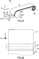
- a needling machine 200 of the circular type which comprises a needling head 210 provided with needles 211 and a support constituted here by a mandrel 220 around which a fibrous structure 30 is intended to be wound .
- the mandrel 220 is rotatable about an axis B.
- the needling head 210 can move, during needling, in a direction Z perpendicular to the surface of the mandrel, this direction also corresponding to a radial direction with respect to to the axis B of the mandrel 220.
- the mandrel 220 is only movable in rotation around the axis B, and the needling head 210 is movable in translation only in the directions X and Z.
- the fibrous structure 30 may be in the form of a fibrous strip stored on a take-up mandrel 230.
- the wound portion forms a first fibrous layer 31 on the mandrel 220.
- the portion which covers the first layer 31 forms a second fibrous layer 32 on the mandrel 220.
- the mandrel 220 is rotated gradually (arrow 221) to make the first layer 31 pass in front of the needling head 210.
- the needling head 210 is animated with a movement along the double arrow 212 in order to needle the whole of the first layer 31.
- the needling head 210 is in a first position relative to the mandrel 220 This first position is defined here in particular by the position along the axis X of the needling head 210 relative to the mandrel 220.
- the movement of the fibrous structure 30 in front of the needling head 210 can be carried out step by step, in particular in order to reduce the shearing of the fibrous layer during needling.
- the figure 4B shows a view of the first layer 31 at the start of its needling and the position of the holes 31a resulting therefrom.
- the step of relative displacement of the mandrel 220 (on which the two fibrous layers 31 and 32 are carried out) is carried out relative to the needling head 210.
- this step corresponds to a translation of the head of needling 210 by a distance ⁇ X in the direction X parallel to the axis of rotation B of the mandrel.
- the distance ⁇ X can be less than or equal to 30 mm (that is to say that the displacement can be between -30mm and + 30mm relative to the first position), or even less than or equal to 15mm (that is that is to say between -15mm and + 15mm relative to the first position), in order to limit the size of the dead zones, that is to say non-needled, in the fibrous layers.
- ⁇ X is not equal to 0.
- the needling head 210 is thus in a second position, different from the first position.
- the needling of the second fibrous layer 32 is carried out, the needling head 210 being in the second position at least at the start of the needling of the second fibrous layer 32.
- the needling of the second fibrous layer 32 can be carried out in the same way as the needling of the first fibrous layer 31.
- the mandrel 220 can rotate around the axis B so as to scroll the second layer 32 in front of the needling head 210 which is moved back and forth in the direction Z.
- the steps of relative displacement of the support relative to the needling head correspond to particular movements of the support or of the head , for example a translation or a rotation, adapted in particular to the machine considered.
- the step of relative displacement of the support relative to the needling head successively comprises several types of movement, for example a translation followed by a rotation or vice versa.
- a fibrous layer may for example comprise a sheet of unidirectional fibers, or a textile sheet having a two-dimensional weaving.
- the fibers of the fibrous layer can be fibers of a refractory material such as carbon, or ceramic fibers, for example made of silicon carbide or glass.
Landscapes
- Engineering & Computer Science (AREA)
- Textile Engineering (AREA)
- Mechanical Engineering (AREA)
- Nonwoven Fabrics (AREA)
- Laminated Bodies (AREA)
- Chemical & Material Sciences (AREA)
- Composite Materials (AREA)
Claims (5)
- Verfahren zur Herstellung einer vernadelten Faserstruktur mittels einer Vernadelungsmaschine (100; 200), die mit einem Vernadelungskopf (110; 210) versehen ist, der mehrere Nadeln umfasst, wobei das Verfahren mindestens die folgenden Schritte umfasst:- Platzieren einer ersten Faserschicht (10; 31) auf einem Träger (120; 220),- Vernadeln der ersten Faserschicht, wobei der Vernadelungskopf sich zumindest am Ende des Vernadelns der ersten Schicht in einer ersten Position in Bezug zu dem Träger befindet,- relatives Verlagern des Trägers in Bezug zu dem Vernadelungskopf, das nach dem Vernadeln der ersten Schicht ausgeführt wird, derart dass der Vernadelungskopf in Bezug zu dem Träger von der ersten Position in eine zweite Position übergeht, die sich von der ersten unterscheidet,- Platzieren einer zweiten Faserschicht (20; 32) auf der vernadelten ersten Faserschicht, und- Vernadeln der zweiten Faserschicht, die auf der ersten Faserschicht platziert ist, wobei der Vernadelungskopf sich zumindest zu Beginn des Vernadelns der zweiten Faserschicht in der zweiten Position in Bezug zu dem Träger befindet,wobei das relative Verlagern so ausgestaltet ist, dass die Nadeln des Vernadelungskopfs nicht an derselben Stelle auf die erste (10; 31) und die zweite Schicht (20; 32) treffen, und
wobei (i) das relative Verlagern eine relative Drehung des Träges (120) in Bezug zu dem Vernadelungskopf (110) umfasst, oder (ii) der Träger (220) ein drehbarer Dorn ist und das relative Verlagern eine relative Translation des Vernadelungskopfs (210) in Bezug zu dem Träger gemäß einer Richtung (X) parallel zu einer Drehachse (B) des Trägers ist. - Verfahren nach Anspruch 1, wobei die relative Drehung des Trägers (120) in Bezug zu dem Vernadelungskopf (110) eine Drehung des Trägers gemäß einer Achse (A) ist, die senkrecht zu einer Fläche (121) des Trägers ist.
- Verfahren nach Anspruch 1 oder 2, wobei der Träger (120) eine Drehung um einen Winkel (α) von nicht null und kleiner oder gleich 5° durchführt.
- Verfahren nach Anspruch 1, wobei der Vernadelungskopf (210) oder der Träger (220) über eine Entfernung (ΔX) von nicht null und kleiner oder gleich 30 mm translatorisch bewegt wird.
- Verfahren zur Herstellung eines Teils aus Verbundmaterial, das eine durch eine Matrix verdichtete Faserverstärkung umfasst, wobei das Verfahren mindestens die folgenden Schritte umfasst:- Herstellen einer vernadelten Faserstruktur, die dazu bestimmt ist, die Faserverstärkung des Teils zu bilden, durch ein Verfahren nach einem der Ansprüche 1 bis 4, und- Bilden einer Matrix in der Porosität der vernadelten Faserstruktur, um das Teil aus Verbundmaterial zu erhalten.
Applications Claiming Priority (1)
| Application Number | Priority Date | Filing Date | Title |
|---|---|---|---|
| FR1751830A FR3063745B1 (fr) | 2017-03-07 | 2017-03-07 | Procede de fabrication d'une structure fibreuse aiguilletee |
Publications (2)
| Publication Number | Publication Date |
|---|---|
| EP3372718A1 EP3372718A1 (de) | 2018-09-12 |
| EP3372718B1 true EP3372718B1 (de) | 2020-01-01 |
Family
ID=59409405
Family Applications (1)
| Application Number | Title | Priority Date | Filing Date |
|---|---|---|---|
| EP18159859.0A Active EP3372718B1 (de) | 2017-03-07 | 2018-03-05 | Herstellungsverfahren einer vernadelten faserstruktur |
Country Status (3)
| Country | Link |
|---|---|
| US (1) | US10704171B2 (de) |
| EP (1) | EP3372718B1 (de) |
| FR (1) | FR3063745B1 (de) |
Families Citing this family (1)
| Publication number | Priority date | Publication date | Assignee | Title |
|---|---|---|---|---|
| FR3095214B1 (fr) | 2019-04-17 | 2021-05-07 | Andritz Asselin Thibeau | Aiguilleteuse ou ligne d’aiguilletage à planches à aiguilles multiples |
Family Cites Families (17)
| Publication number | Priority date | Publication date | Assignee | Title |
|---|---|---|---|---|
| US460805A (en) * | 1891-10-06 | Augusta whiffle | ||
| GB1145761A (en) | 1965-09-13 | 1969-03-19 | Ici Ltd | Nonwoven fabrics and a process for making them |
| US3431611A (en) | 1966-09-16 | 1969-03-11 | Gen Electric | Method for forming nonwoven electric blanket shells |
| US3909891A (en) * | 1972-01-18 | 1975-10-07 | Dilo Kg Oskar | Needling Apparatus |
| US3845529A (en) | 1972-08-31 | 1974-11-05 | Riegel Textile Corp | Apparatus and process for tacking fabrics |
| FR2557550B1 (fr) * | 1983-12-28 | 1986-05-30 | Europ Propulsion | Procede et appareillage pour la fabrication de structures tridimensionnelles de revolution |
| US4790052A (en) * | 1983-12-28 | 1988-12-13 | Societe Europeenne De Propulsion | Process for manufacturing homogeneously needled three-dimensional structures of fibrous material |
| US4878278A (en) * | 1987-08-05 | 1989-11-07 | Wangner Systems Corporation | Method for manufacture of paper making fabrics |
| AT400852B (de) * | 1994-05-02 | 1996-04-25 | Fehrer Textilmasch | Vorrichtung zum nadeln eines kreisförmigen, insbesondere kreisringförmigen faservlieses |
| US5662855A (en) * | 1994-05-17 | 1997-09-02 | The B.F. Goodrich Company | Method of making near net shaped fibrous structures |
| FR2741634B1 (fr) * | 1995-11-27 | 1998-04-17 | Europ Propulsion | Procede pour la realisation de preformes fibreuses destinees a la fabrication de pieces annulaires en materiau composite |
| US6568050B2 (en) | 2001-02-26 | 2003-05-27 | Messier-Bugatti | Method and installation for advancing a needled fiber plate |
| FR2824084B1 (fr) * | 2001-04-30 | 2003-08-01 | Messier Bugatti | Alimentation aiguilleteuse par bande spirale continue |
| US7430790B1 (en) | 2005-04-26 | 2008-10-07 | Don Bowles | Felting machine |
| ATE485414T1 (de) | 2007-08-09 | 2010-11-15 | Dilo Kg Maschf Oskar | Anlage und verfahren zur vernadelung einer vliesbahn |
| EP3003667A4 (de) * | 2013-05-31 | 2017-03-22 | Advanced Carbon Technologies, Llc | Verfahren zur herstellung einer tuchvorform von niedriger dichte |
| FR3007428B1 (fr) * | 2013-06-20 | 2015-10-16 | Messier Bugatti Dowty | Table et procede d'aiguilletage d'une structure textile formee a partir d'une preforme fibreuse annulaire avec decalage radial de la tete d'aiguilletage |
-
2017
- 2017-03-07 FR FR1751830A patent/FR3063745B1/fr active Active
-
2018
- 2018-03-05 EP EP18159859.0A patent/EP3372718B1/de active Active
- 2018-03-06 US US15/913,370 patent/US10704171B2/en active Active
Non-Patent Citations (1)
| Title |
|---|
| None * |
Also Published As
| Publication number | Publication date |
|---|---|
| US20180257331A1 (en) | 2018-09-13 |
| FR3063745B1 (fr) | 2021-06-11 |
| FR3063745A1 (fr) | 2018-09-14 |
| EP3372718A1 (de) | 2018-09-12 |
| US10704171B2 (en) | 2020-07-07 |
Similar Documents
| Publication | Publication Date | Title |
|---|---|---|
| EP2341175B1 (de) | Vernadelungsmaschine für Textilstruktur aus ringförmigem vorgeformtem Fasermaterial | |
| EP2067757B1 (de) | Herstellungsverfahren von Verbundwerkstoffteilen mit Karbonfaserverstärkung | |
| CA2147040C (fr) | Procede et machine pour la realisation d'une armature pour une piece de matiere composite | |
| EP2816147B1 (de) | Tisch und Verfahren zur Vernadelung einer Textilstruktur, die aus einer ringförmigen Faservorform gebildet wird, mit radialer Versetzung des Vernadelungskopfs | |
| EP0296970B1 (de) | Verfahren und Vorrichtung zur Vernadelung einer Glasfasermatte und auf Basis dieser Matte hergestellter Verbundwerkstoff | |
| EP3372718B1 (de) | Herstellungsverfahren einer vernadelten faserstruktur | |
| EP3843965B1 (de) | Verfahren zur herstellung eines zusammengesetzten vorformlings zur herstellung einer verbundplatte mit doppelter krümmungsgeometrie | |
| EP2813610B1 (de) | Zugvorrichtung mit nadeln für zu vernadelnde spiralförmige faserbahn | |
| WO2002088450A1 (fr) | Machine d'aiguilletage circulaire munie d'un dispositif d'evacuation automatique de preformes | |
| EP0161010B1 (de) | Verfahren und Vorrichtung zum Vereinzeln flexibler Flächengebilde, insbesondere Textilwaren und Maschine zum Vereinzeln und zur Führung dieser Flächengebilde | |
| EP3372717B1 (de) | Vernadelungsverfahren einer faserschicht | |
| FR2669854A1 (fr) | Procede d'elaboration d'une preforme fibreuse d'epaisseur evolutive pour fabriquer une piece en materiau composite du type a matrice carbone ou ceramique. | |
| EP0687315B1 (de) | Mehrachsiges dreidimensionales gewebe und herstellungsverfahren dazu | |
| FR2779749A1 (fr) | Armature fibreuse pour piece de matiere composite, ainsi que procede et dispositif pour sa realisation | |
| CA2617676C (fr) | Dispositif de tricotage pour la confection d'un textile double face epais | |
| CA2411710A1 (fr) | Procede de realisation d'une preforme textile multidirectionnelle, dispositif pour sa mise en oeuvre et preforme ainsi obtenue | |
| FR2919223A1 (fr) | Stratifie tridimensionnel flexible de haute resistance aux piqures et perforations, gant et enveloppe de pneumatique constitues de ce stratifie | |
| FR3013627A1 (fr) | Outillage et procede de mise en forme d'une texture fibreuse | |
| FR3072659A1 (fr) | Récipient réfractaire en un matériau céramique, compact vert pour un tel récipient, procédé de fabrication d'un récipient réfractaire en un matériau céramique ainsi que d'un compact vert prévu à cette fin | |
| WO2018073512A1 (fr) | Procede de fabrication d'un renfort textile, et renfort associe | |
| FR3055625A1 (fr) | Preforme fibreuse pour fabriquer une piece en materiau composite et procede associe |
Legal Events
| Date | Code | Title | Description |
|---|---|---|---|
| PUAI | Public reference made under article 153(3) epc to a published international application that has entered the european phase |
Free format text: ORIGINAL CODE: 0009012 |
|
| STAA | Information on the status of an ep patent application or granted ep patent |
Free format text: STATUS: REQUEST FOR EXAMINATION WAS MADE |
|
| 17P | Request for examination filed |
Effective date: 20180305 |
|
| AK | Designated contracting states |
Kind code of ref document: A1 Designated state(s): AL AT BE BG CH CY CZ DE DK EE ES FI FR GB GR HR HU IE IS IT LI LT LU LV MC MK MT NL NO PL PT RO RS SE SI SK SM TR |
|
| AX | Request for extension of the european patent |
Extension state: BA ME |
|
| GRAP | Despatch of communication of intention to grant a patent |
Free format text: ORIGINAL CODE: EPIDOSNIGR1 |
|
| STAA | Information on the status of an ep patent application or granted ep patent |
Free format text: STATUS: GRANT OF PATENT IS INTENDED |
|
| INTG | Intention to grant announced |
Effective date: 20190723 |
|
| GRAS | Grant fee paid |
Free format text: ORIGINAL CODE: EPIDOSNIGR3 |
|
| GRAA | (expected) grant |
Free format text: ORIGINAL CODE: 0009210 |
|
| STAA | Information on the status of an ep patent application or granted ep patent |
Free format text: STATUS: THE PATENT HAS BEEN GRANTED |
|
| AK | Designated contracting states |
Kind code of ref document: B1 Designated state(s): AL AT BE BG CH CY CZ DE DK EE ES FI FR GB GR HR HU IE IS IT LI LT LU LV MC MK MT NL NO PL PT RO RS SE SI SK SM TR |
|
| REG | Reference to a national code |
Ref country code: GB Ref legal event code: FG4D Free format text: NOT ENGLISH |
|
| REG | Reference to a national code |
Ref country code: CH Ref legal event code: EP Ref country code: AT Ref legal event code: REF Ref document number: 1219889 Country of ref document: AT Kind code of ref document: T Effective date: 20200115 |
|
| REG | Reference to a national code |
Ref country code: IE Ref legal event code: FG4D Free format text: LANGUAGE OF EP DOCUMENT: FRENCH |
|
| REG | Reference to a national code |
Ref country code: DE Ref legal event code: R096 Ref document number: 602018001823 Country of ref document: DE |
|
| REG | Reference to a national code |
Ref country code: NL Ref legal event code: MP Effective date: 20200101 |
|
| REG | Reference to a national code |
Ref country code: LT Ref legal event code: MG4D |
|
| PG25 | Lapsed in a contracting state [announced via postgrant information from national office to epo] |
Ref country code: CZ Free format text: LAPSE BECAUSE OF FAILURE TO SUBMIT A TRANSLATION OF THE DESCRIPTION OR TO PAY THE FEE WITHIN THE PRESCRIBED TIME-LIMIT Effective date: 20200101 Ref country code: PT Free format text: LAPSE BECAUSE OF FAILURE TO SUBMIT A TRANSLATION OF THE DESCRIPTION OR TO PAY THE FEE WITHIN THE PRESCRIBED TIME-LIMIT Effective date: 20200527 Ref country code: FI Free format text: LAPSE BECAUSE OF FAILURE TO SUBMIT A TRANSLATION OF THE DESCRIPTION OR TO PAY THE FEE WITHIN THE PRESCRIBED TIME-LIMIT Effective date: 20200101 Ref country code: LT Free format text: LAPSE BECAUSE OF FAILURE TO SUBMIT A TRANSLATION OF THE DESCRIPTION OR TO PAY THE FEE WITHIN THE PRESCRIBED TIME-LIMIT Effective date: 20200101 Ref country code: RS Free format text: LAPSE BECAUSE OF FAILURE TO SUBMIT A TRANSLATION OF THE DESCRIPTION OR TO PAY THE FEE WITHIN THE PRESCRIBED TIME-LIMIT Effective date: 20200101 Ref country code: NL Free format text: LAPSE BECAUSE OF FAILURE TO SUBMIT A TRANSLATION OF THE DESCRIPTION OR TO PAY THE FEE WITHIN THE PRESCRIBED TIME-LIMIT Effective date: 20200101 Ref country code: NO Free format text: LAPSE BECAUSE OF FAILURE TO SUBMIT A TRANSLATION OF THE DESCRIPTION OR TO PAY THE FEE WITHIN THE PRESCRIBED TIME-LIMIT Effective date: 20200401 |
|
| PG25 | Lapsed in a contracting state [announced via postgrant information from national office to epo] |
Ref country code: IS Free format text: LAPSE BECAUSE OF FAILURE TO SUBMIT A TRANSLATION OF THE DESCRIPTION OR TO PAY THE FEE WITHIN THE PRESCRIBED TIME-LIMIT Effective date: 20200501 Ref country code: BG Free format text: LAPSE BECAUSE OF FAILURE TO SUBMIT A TRANSLATION OF THE DESCRIPTION OR TO PAY THE FEE WITHIN THE PRESCRIBED TIME-LIMIT Effective date: 20200401 Ref country code: SE Free format text: LAPSE BECAUSE OF FAILURE TO SUBMIT A TRANSLATION OF THE DESCRIPTION OR TO PAY THE FEE WITHIN THE PRESCRIBED TIME-LIMIT Effective date: 20200101 Ref country code: LV Free format text: LAPSE BECAUSE OF FAILURE TO SUBMIT A TRANSLATION OF THE DESCRIPTION OR TO PAY THE FEE WITHIN THE PRESCRIBED TIME-LIMIT Effective date: 20200101 Ref country code: HR Free format text: LAPSE BECAUSE OF FAILURE TO SUBMIT A TRANSLATION OF THE DESCRIPTION OR TO PAY THE FEE WITHIN THE PRESCRIBED TIME-LIMIT Effective date: 20200101 |
|
| REG | Reference to a national code |
Ref country code: DE Ref legal event code: R097 Ref document number: 602018001823 Country of ref document: DE |
|
| PG25 | Lapsed in a contracting state [announced via postgrant information from national office to epo] |
Ref country code: DK Free format text: LAPSE BECAUSE OF FAILURE TO SUBMIT A TRANSLATION OF THE DESCRIPTION OR TO PAY THE FEE WITHIN THE PRESCRIBED TIME-LIMIT Effective date: 20200101 Ref country code: MC Free format text: LAPSE BECAUSE OF FAILURE TO SUBMIT A TRANSLATION OF THE DESCRIPTION OR TO PAY THE FEE WITHIN THE PRESCRIBED TIME-LIMIT Effective date: 20200101 Ref country code: EE Free format text: LAPSE BECAUSE OF FAILURE TO SUBMIT A TRANSLATION OF THE DESCRIPTION OR TO PAY THE FEE WITHIN THE PRESCRIBED TIME-LIMIT Effective date: 20200101 Ref country code: SM Free format text: LAPSE BECAUSE OF FAILURE TO SUBMIT A TRANSLATION OF THE DESCRIPTION OR TO PAY THE FEE WITHIN THE PRESCRIBED TIME-LIMIT Effective date: 20200101 Ref country code: RO Free format text: LAPSE BECAUSE OF FAILURE TO SUBMIT A TRANSLATION OF THE DESCRIPTION OR TO PAY THE FEE WITHIN THE PRESCRIBED TIME-LIMIT Effective date: 20200101 Ref country code: SK Free format text: LAPSE BECAUSE OF FAILURE TO SUBMIT A TRANSLATION OF THE DESCRIPTION OR TO PAY THE FEE WITHIN THE PRESCRIBED TIME-LIMIT Effective date: 20200101 Ref country code: ES Free format text: LAPSE BECAUSE OF FAILURE TO SUBMIT A TRANSLATION OF THE DESCRIPTION OR TO PAY THE FEE WITHIN THE PRESCRIBED TIME-LIMIT Effective date: 20200101 |
|
| PLBE | No opposition filed within time limit |
Free format text: ORIGINAL CODE: 0009261 |
|
| STAA | Information on the status of an ep patent application or granted ep patent |
Free format text: STATUS: NO OPPOSITION FILED WITHIN TIME LIMIT |
|
| REG | Reference to a national code |
Ref country code: AT Ref legal event code: MK05 Ref document number: 1219889 Country of ref document: AT Kind code of ref document: T Effective date: 20200101 |
|
| 26N | No opposition filed |
Effective date: 20201002 |
|
| REG | Reference to a national code |
Ref country code: BE Ref legal event code: MM Effective date: 20200331 |
|
| PG25 | Lapsed in a contracting state [announced via postgrant information from national office to epo] |
Ref country code: LU Free format text: LAPSE BECAUSE OF NON-PAYMENT OF DUE FEES Effective date: 20200305 |
|
| PG25 | Lapsed in a contracting state [announced via postgrant information from national office to epo] |
Ref country code: IE Free format text: LAPSE BECAUSE OF NON-PAYMENT OF DUE FEES Effective date: 20200305 Ref country code: AT Free format text: LAPSE BECAUSE OF FAILURE TO SUBMIT A TRANSLATION OF THE DESCRIPTION OR TO PAY THE FEE WITHIN THE PRESCRIBED TIME-LIMIT Effective date: 20200101 |
|
| PG25 | Lapsed in a contracting state [announced via postgrant information from national office to epo] |
Ref country code: PL Free format text: LAPSE BECAUSE OF FAILURE TO SUBMIT A TRANSLATION OF THE DESCRIPTION OR TO PAY THE FEE WITHIN THE PRESCRIBED TIME-LIMIT Effective date: 20200101 Ref country code: SI Free format text: LAPSE BECAUSE OF FAILURE TO SUBMIT A TRANSLATION OF THE DESCRIPTION OR TO PAY THE FEE WITHIN THE PRESCRIBED TIME-LIMIT Effective date: 20200101 Ref country code: BE Free format text: LAPSE BECAUSE OF NON-PAYMENT OF DUE FEES Effective date: 20200331 |
|
| REG | Reference to a national code |
Ref country code: CH Ref legal event code: PL |
|
| PG25 | Lapsed in a contracting state [announced via postgrant information from national office to epo] |
Ref country code: CH Free format text: LAPSE BECAUSE OF NON-PAYMENT OF DUE FEES Effective date: 20210331 Ref country code: LI Free format text: LAPSE BECAUSE OF NON-PAYMENT OF DUE FEES Effective date: 20210331 |
|
| PG25 | Lapsed in a contracting state [announced via postgrant information from national office to epo] |
Ref country code: TR Free format text: LAPSE BECAUSE OF FAILURE TO SUBMIT A TRANSLATION OF THE DESCRIPTION OR TO PAY THE FEE WITHIN THE PRESCRIBED TIME-LIMIT Effective date: 20200101 Ref country code: MT Free format text: LAPSE BECAUSE OF FAILURE TO SUBMIT A TRANSLATION OF THE DESCRIPTION OR TO PAY THE FEE WITHIN THE PRESCRIBED TIME-LIMIT Effective date: 20200101 Ref country code: CY Free format text: LAPSE BECAUSE OF FAILURE TO SUBMIT A TRANSLATION OF THE DESCRIPTION OR TO PAY THE FEE WITHIN THE PRESCRIBED TIME-LIMIT Effective date: 20200101 |
|
| PG25 | Lapsed in a contracting state [announced via postgrant information from national office to epo] |
Ref country code: MK Free format text: LAPSE BECAUSE OF FAILURE TO SUBMIT A TRANSLATION OF THE DESCRIPTION OR TO PAY THE FEE WITHIN THE PRESCRIBED TIME-LIMIT Effective date: 20200101 Ref country code: AL Free format text: LAPSE BECAUSE OF FAILURE TO SUBMIT A TRANSLATION OF THE DESCRIPTION OR TO PAY THE FEE WITHIN THE PRESCRIBED TIME-LIMIT Effective date: 20200101 |
|
| PG25 | Lapsed in a contracting state [announced via postgrant information from national office to epo] |
Ref country code: GR Free format text: LAPSE BECAUSE OF FAILURE TO SUBMIT A TRANSLATION OF THE DESCRIPTION OR TO PAY THE FEE WITHIN THE PRESCRIBED TIME-LIMIT Effective date: 20200101 |
|
| REG | Reference to a national code |
Ref country code: DE Ref legal event code: R082 Ref document number: 602018001823 Country of ref document: DE Representative=s name: CBDL PATENTANWAELTE GBR, DE Ref country code: DE Ref legal event code: R082 Ref document number: 602018001823 Country of ref document: DE Representative=s name: CBDL PATENTANWAELTE EGBR, DE |
|
| P01 | Opt-out of the competence of the unified patent court (upc) registered |
Effective date: 20230612 |
|
| PGFP | Annual fee paid to national office [announced via postgrant information from national office to epo] |
Ref country code: GB Payment date: 20260324 Year of fee payment: 9 |
|
| PGFP | Annual fee paid to national office [announced via postgrant information from national office to epo] |
Ref country code: DE Payment date: 20260319 Year of fee payment: 9 |
|
| PGFP | Annual fee paid to national office [announced via postgrant information from national office to epo] |
Ref country code: IT Payment date: 20260324 Year of fee payment: 9 |
|
| PGFP | Annual fee paid to national office [announced via postgrant information from national office to epo] |
Ref country code: FR Payment date: 20260320 Year of fee payment: 9 |