EP3372183B1 - Instrument for ablation - Google Patents
Instrument for ablation Download PDFInfo
- Publication number
- EP3372183B1 EP3372183B1 EP17160265.9A EP17160265A EP3372183B1 EP 3372183 B1 EP3372183 B1 EP 3372183B1 EP 17160265 A EP17160265 A EP 17160265A EP 3372183 B1 EP3372183 B1 EP 3372183B1
- Authority
- EP
- European Patent Office
- Prior art keywords
- gas supply
- instrument
- supply line
- connecting element
- distal end
- Prior art date
- Legal status (The legal status is an assumption and is not a legal conclusion. Google has not performed a legal analysis and makes no representation as to the accuracy of the status listed.)
- Active
Links
Images


Classifications
-
- A—HUMAN NECESSITIES
- A61—MEDICAL OR VETERINARY SCIENCE; HYGIENE
- A61B—DIAGNOSIS; SURGERY; IDENTIFICATION
- A61B18/00—Surgical instruments, devices or methods for transferring non-mechanical forms of energy to or from the body
- A61B18/04—Surgical instruments, devices or methods for transferring non-mechanical forms of energy to or from the body by heating
- A61B18/12—Surgical instruments, devices or methods for transferring non-mechanical forms of energy to or from the body by heating by passing a current through the tissue to be heated, e.g. high-frequency current
- A61B18/14—Probes or electrodes therefor
-
- A—HUMAN NECESSITIES
- A61—MEDICAL OR VETERINARY SCIENCE; HYGIENE
- A61B—DIAGNOSIS; SURGERY; IDENTIFICATION
- A61B18/00—Surgical instruments, devices or methods for transferring non-mechanical forms of energy to or from the body
- A61B18/04—Surgical instruments, devices or methods for transferring non-mechanical forms of energy to or from the body by heating
- A61B18/042—Surgical instruments, devices or methods for transferring non-mechanical forms of energy to or from the body by heating using additional gas becoming plasma
-
- A—HUMAN NECESSITIES
- A61—MEDICAL OR VETERINARY SCIENCE; HYGIENE
- A61B—DIAGNOSIS; SURGERY; IDENTIFICATION
- A61B1/00—Instruments for performing medical examinations of the interior of cavities or tubes of the body by visual or photographical inspection, e.g. endoscopes; Illuminating arrangements therefor
- A61B1/00064—Constructional details of the endoscope body
- A61B1/00071—Insertion part of the endoscope body
- A61B1/0008—Insertion part of the endoscope body characterised by distal tip features
- A61B1/00087—Tools
-
- A—HUMAN NECESSITIES
- A61—MEDICAL OR VETERINARY SCIENCE; HYGIENE
- A61B—DIAGNOSIS; SURGERY; IDENTIFICATION
- A61B1/00—Instruments for performing medical examinations of the interior of cavities or tubes of the body by visual or photographical inspection, e.g. endoscopes; Illuminating arrangements therefor
- A61B1/04—Instruments for performing medical examinations of the interior of cavities or tubes of the body by visual or photographical inspection, e.g. endoscopes; Illuminating arrangements therefor combined with photographic or television appliances
- A61B1/042—Instruments for performing medical examinations of the interior of cavities or tubes of the body by visual or photographical inspection, e.g. endoscopes; Illuminating arrangements therefor combined with photographic or television appliances characterised by a proximal camera, e.g. a CCD camera
-
- A—HUMAN NECESSITIES
- A61—MEDICAL OR VETERINARY SCIENCE; HYGIENE
- A61B—DIAGNOSIS; SURGERY; IDENTIFICATION
- A61B18/00—Surgical instruments, devices or methods for transferring non-mechanical forms of energy to or from the body
- A61B18/04—Surgical instruments, devices or methods for transferring non-mechanical forms of energy to or from the body by heating
- A61B18/12—Surgical instruments, devices or methods for transferring non-mechanical forms of energy to or from the body by heating by passing a current through the tissue to be heated, e.g. high-frequency current
- A61B18/1206—Generators therefor
- A61B18/1233—Generators therefor with circuits for assuring patient safety
-
- A—HUMAN NECESSITIES
- A61—MEDICAL OR VETERINARY SCIENCE; HYGIENE
- A61B—DIAGNOSIS; SURGERY; IDENTIFICATION
- A61B18/00—Surgical instruments, devices or methods for transferring non-mechanical forms of energy to or from the body
- A61B18/04—Surgical instruments, devices or methods for transferring non-mechanical forms of energy to or from the body by heating
- A61B18/12—Surgical instruments, devices or methods for transferring non-mechanical forms of energy to or from the body by heating by passing a current through the tissue to be heated, e.g. high-frequency current
- A61B18/14—Probes or electrodes therefor
- A61B18/1492—Probes or electrodes therefor having a flexible, catheter-like structure, e.g. for heart ablation
-
- A—HUMAN NECESSITIES
- A61—MEDICAL OR VETERINARY SCIENCE; HYGIENE
- A61B—DIAGNOSIS; SURGERY; IDENTIFICATION
- A61B5/00—Measuring for diagnostic purposes; Identification of persons
- A61B5/24—Detecting, measuring or recording bioelectric or biomagnetic signals of the body or parts thereof
- A61B5/25—Bioelectric electrodes therefor
- A61B5/279—Bioelectric electrodes therefor specially adapted for particular uses
- A61B5/28—Bioelectric electrodes therefor specially adapted for particular uses for electrocardiography [ECG]
- A61B5/283—Invasive
- A61B5/287—Holders for multiple electrodes, e.g. electrode catheters for electrophysiological study [EPS]
-
- A—HUMAN NECESSITIES
- A61—MEDICAL OR VETERINARY SCIENCE; HYGIENE
- A61B—DIAGNOSIS; SURGERY; IDENTIFICATION
- A61B1/00—Instruments for performing medical examinations of the interior of cavities or tubes of the body by visual or photographical inspection, e.g. endoscopes; Illuminating arrangements therefor
- A61B1/273—Instruments for performing medical examinations of the interior of cavities or tubes of the body by visual or photographical inspection, e.g. endoscopes; Illuminating arrangements therefor for the upper alimentary canal, e.g. oesophagoscopes, gastroscopes
- A61B1/2736—Gastroscopes
-
- A—HUMAN NECESSITIES
- A61—MEDICAL OR VETERINARY SCIENCE; HYGIENE
- A61B—DIAGNOSIS; SURGERY; IDENTIFICATION
- A61B17/00—Surgical instruments, devices or methods, e.g. tourniquets
- A61B17/00234—Surgical instruments, devices or methods, e.g. tourniquets for minimally invasive surgery
- A61B2017/00238—Type of minimally invasive operation
- A61B2017/00269—Type of minimally invasive operation endoscopic mucosal resection EMR
-
- A—HUMAN NECESSITIES
- A61—MEDICAL OR VETERINARY SCIENCE; HYGIENE
- A61B—DIAGNOSIS; SURGERY; IDENTIFICATION
- A61B17/00—Surgical instruments, devices or methods, e.g. tourniquets
- A61B2017/00477—Coupling
-
- A—HUMAN NECESSITIES
- A61—MEDICAL OR VETERINARY SCIENCE; HYGIENE
- A61B—DIAGNOSIS; SURGERY; IDENTIFICATION
- A61B18/00—Surgical instruments, devices or methods for transferring non-mechanical forms of energy to or from the body
- A61B2018/00005—Cooling or heating of the probe or tissue immediately surrounding the probe
- A61B2018/00011—Cooling or heating of the probe or tissue immediately surrounding the probe with fluids
- A61B2018/00029—Cooling or heating of the probe or tissue immediately surrounding the probe with fluids open
-
- A—HUMAN NECESSITIES
- A61—MEDICAL OR VETERINARY SCIENCE; HYGIENE
- A61B—DIAGNOSIS; SURGERY; IDENTIFICATION
- A61B18/00—Surgical instruments, devices or methods for transferring non-mechanical forms of energy to or from the body
- A61B2018/00053—Mechanical features of the instrument of device
- A61B2018/00166—Multiple lumina
-
- A—HUMAN NECESSITIES
- A61—MEDICAL OR VETERINARY SCIENCE; HYGIENE
- A61B—DIAGNOSIS; SURGERY; IDENTIFICATION
- A61B18/00—Surgical instruments, devices or methods for transferring non-mechanical forms of energy to or from the body
- A61B2018/00315—Surgical instruments, devices or methods for transferring non-mechanical forms of energy to or from the body for treatment of particular body parts
- A61B2018/00482—Digestive system
- A61B2018/00494—Stomach, intestines or bowel
-
- A—HUMAN NECESSITIES
- A61—MEDICAL OR VETERINARY SCIENCE; HYGIENE
- A61B—DIAGNOSIS; SURGERY; IDENTIFICATION
- A61B18/00—Surgical instruments, devices or methods for transferring non-mechanical forms of energy to or from the body
- A61B2018/00571—Surgical instruments, devices or methods for transferring non-mechanical forms of energy to or from the body for achieving a particular surgical effect
- A61B2018/00577—Ablation
- A61B2018/00583—Coblation, i.e. ablation using a cold plasma
-
- A—HUMAN NECESSITIES
- A61—MEDICAL OR VETERINARY SCIENCE; HYGIENE
- A61B—DIAGNOSIS; SURGERY; IDENTIFICATION
- A61B18/00—Surgical instruments, devices or methods for transferring non-mechanical forms of energy to or from the body
- A61B2018/00982—Surgical instruments, devices or methods for transferring non-mechanical forms of energy to or from the body combined with or comprising means for visual or photographic inspections inside the body, e.g. endoscopes
-
- A—HUMAN NECESSITIES
- A61—MEDICAL OR VETERINARY SCIENCE; HYGIENE
- A61B—DIAGNOSIS; SURGERY; IDENTIFICATION
- A61B2218/00—Details of surgical instruments, devices or methods for transferring non-mechanical forms of energy to or from the body
- A61B2218/001—Details of surgical instruments, devices or methods for transferring non-mechanical forms of energy to or from the body having means for irrigation and/or aspiration of substances to and/or from the surgical site
- A61B2218/002—Irrigation
- A61B2218/005—Irrigation using gas or vapor, e.g. for protection or purging
Definitions
- the invention relates to a device for ablation, in particular for mucosa ablation.
- WO 2008/090004 A1 describes a bipolar instrument for treating tissue with two channels, in each of which an electrode is arranged.
- the channels serve to supply inert gas to the electrodes to form an arc between the two electrodes.
- Therapeutic mucosa ablation for example, for tumor ablation or destruction of gastric wall-influencing cells, advantageously for weight loss, is typically performed by endoscopic intervention, with special probes for ablation.
- this is from the WO 2011/022069 A2 an endoscope with an end cap which is to be placed on the mucosa, and in whose interior an argon plasma coagulation is performed.
- the cap is intended to limit the range of action of argon plasma coagulation and thus define mucosal coagulation.
- the large-area mucosa ablation places particular demands on the dentist with regard to patience and dexterity. This is especially true when flexible instruments such as polypectomy snares or the like intended for general use are used. With such loops only a resection of the mucosa of about 2 cm 2 is performed in one step. In the fundic and cardiac area of the stomach, resection using a flexible endoscope is very difficult. There is also the risk of perforation.
- the instrument according to the invention is suitable for large-area tissue treatment, preferably for tissue ablation, for example for mucosa ablation.
- the instrument according to the invention has at least a first gas supply line and a second gas supply line, wherein the gas supply lines of the supply of a gas, preferably an inert gas, in particular argon serve.
- a first electrode is at least partially disposed in the first gas supply line.
- a second electrode is at least partially disposed in the second gas supply line.
- the first gas supply line and the second gas supply line are arranged relative to each other such that the distal end of the first gas supply line forms an acute angle with the distal end of the second gas supply line so that the distal ends of the gas supply lines diverge distally.
- gas flow may be produced in the end of the first gas supply line when the gas supply lines with gas are pressurized, and gas flow in the end of the second gas supply line, the flow directions of the two gas streams enclosing the acute angle.
- the angle is preferably between at least 1 ° and a maximum of 60 °, more preferably between at least 1 ° and a maximum of 30 °, for example 10 °.
- the first electrode and the second electrode may also subtend an acute angle, for example, of the same amount, such that the first electrode and the second electrode diverge distally.
- the first gas supply line and the second gas supply line are arranged to each other such that a free space is arranged between the distal end of the first gas supply line and the distal end of the second gas supply line. This allows a view between the ends of the gas supply lines to the area of action of the instrument in front of the distal ends of the gas supply lines.
- a plasma for example an argon plasma
- the plasma can be used to treat the tissue lying in front of the electrodes.
- the treatment includes, in particular, cutting and / or coagulating.
- the plasma streams emerging from the two ends of the gas supply lines can together form an approximately fan-shaped stream, ie a jet with a non-circular (oval or strip-like) cross-section.
- the outlet openings of the two gas supply lines are preferably on a line which is oriented transversely to the direction of movement of the instrument.
- the inventive concept paves the way to the design of a particularly narrow, slender end of the instrument that can hardly be wider or, in some cases, narrower than the trace of coagulated mucosal tissue produced by it.
- the user of the instrument Due to the clearance between the ends of the gas supply lines, the user of the instrument has an improved view of the area of action of the instrument in front of the distal ends of the gas supply lines or in front of the ends of the electrodes. With the clearance, the user of the instrument is preferably given the opportunity to look at the plasma treatment of tissue with the instrument obliquely to the longitudinal axis of the distal end of the instrument between the distal ends of the gas supply lines through the space on the sphere of action of the instrument.
- the heat capacity of the instrument at the distal end of the instrument is relatively low due to the free space.
- the end of the instrument becomes hot due to the plasma treatment, a faster cooling of the end of the instrument can be achieved, so that the instrument can be removed from the body of the patient relatively short time after the plasma treatment without the risk of injury to healthy tissue There is a hot end of the instrument. Due to the "missing" material in the free space, tissue adhesion does not occur there hot material.
- the connecting element for the instrument according to the invention has a seat for the first gas supply line and a seat for the second gas supply line.
- the seats are configured such that the gas supply lines in the seats can be arranged such that the distal ends of the gas supply lines form an acute angle with each other as described so that the gas supply lines diverge distally at their distal ends.
- the seats are preferably designed such that they predetermine a certain amount of the angle between the ends of the gas supply lines.
- the seats are arranged so that the gas supply lines in the seats can be arranged such that between the distal end of the first gas supply line and the distal end of the second gas supply line, the free space is arranged, which provides a view between the ends of the gas supply lines to the tissue allowed in front of the distal ends of the gas supply lines.
- the seats of the connecting element may have means for axially fixing the gas supply lines in the connecting element.
- the seats may have interlocking connection means, such as one or more stops or means for forming a snap-latch connection and / or means for forming a frictional connection between the gas supply line and the connection element.
- the seats are adapted to set a certain amount of the distance of the ends of the gas supply lines to each other and / or with respect to the distal end of the connecting element.
- the connection means are adapted to be able to establish and / or release the connection between a gas supply line and the connection element while no connection and / or connection is established between the other gas supply line and the connection element.
- the space between the distal ends of the gas supply lines is preferably open distally on both sides transversely to the direction in order to be able to look at the area of the tissue in front of the instrument from outside the instrument between the ends of the gas supply lines.
- the free space preferably extends from the distal end of the first gas supply line to the distal end of the second gas supply line.
- the free space preferably widens distally between the gas supply lines. The clearance may widen distally, for example, at the acute angle that the distal end of the first gas supply conduit encloses with the distal end of the second gas supply conduit.
- the instrument according to the invention is attached to the outside of an endoscope.
- the endoscope may, for example, have a working channel, the instrument preferably being arranged outside the working channel.
- the instrument can be guided on the outside of the endoscope. This allows the instrument to be displaced, for example, along the axis of the distal end of the endoscope.
- a light source for illuminating the tissue in front of the instrument and / or an input for an image to the proximal Have end of the endoscope transmitting device (image guide).
- the instrument may be disposed on the endoscope such that the user may look at the tissue in front of the instrument through the image conductor between the ends of the gas supply lines.
- a displaceability of the distal end of the instrument for ablation in the axial direction, i. in the longitudinal direction of the endoscope, facilitates handling especially in the ablation of tissue layers in large hollow organs, such as ablation of the mucosa in the stomach.
- the distal end of the instrument can be extended, for example, between 0 mm and 100 mm, with an extendability of up to 50 mm being considered advantageous, further 30 mm extension length being considered optimal.
- connection which is assigned to the connecting element and is fastened to the endoscope, has a recess which is complementary to a non-circular cross-section of the connecting element and into which the connecting element can retract in the proximal direction when retracted.
- the non-circular cross section may be formed in particular at the distal end of the connecting element.
- the connecting element or the instrument end is thereby limited in the version in its rotational mobility. This considerably facilitates the handling of the ablation instrument according to the invention. In particular, it can be ensured that the connecting element or the instrument end is arranged by retraction in a specific rotational position, which it can maintain even after pushing out.
- the connecting element or the instrument end can preferably also in the extended state, for example be brought by a survey on the tube at the proximal end of the socket and a designated groove in a desired position.
- the instrument, fastener, system, and method of the invention may be further formed with one or more of the features described herein.
- the first gas supply line and the first electrode may belong to a first probe and the second gas supply line and the second electrode may belong to another second probe, wherein the probes may be arranged to be used separately, independently of the other probe for the plasma treatment can.
- the first probe and the second probe may be held with the connector such that the distal end of the gas supply line of the first probe encloses the acute angle with the distal end of the gas supply line of the second probe, and between the distal end of the first gas supply line and the distal end End of the second gas supply line of the free space is arranged.
- At least one of the probes is preferably interchangeably attached or attachable to the connector in the instrument. In this way, the user can exchange one or more of the probes arranged by means of the connecting element for an instrument with a probe desired by the user.
- the ends of the gas supply lines may extend distally over the connecting element survive.
- the connection element can thereby be arranged outside the range of elevated temperature, for example, outside a region having a temperature which exceeds the temperature up to which the material of which the connection element is made, when treated with the aid of the instrument.
- the seats of the connecting element for the gas supply lines may be formed such that they determine the position of a gas supply line in the instrument with respect to the other gas supply line.
- the seats may correspondingly define a distal projection of the ends of the gas supply lines via the distal end of the connecting element.
- the electrodes are preferably arranged outside the connecting element. This can reduce the thermal load of the connecting element.
- the connecting element may be made of material having a relatively low thermal capacity.
- the arrangement of the electrodes outside the connecting element can also be made to avoid leakage currents between the electrodes via the connecting element. The risk of flashovers is thus reduced.
- connecting element for example, ceramic or plastic, such as PEEK, PA, or elastomer, such as silicone in question.
- the first gas supply line preferably has a plastic line which extends from proximal in front of the connecting element through the connecting element to distally without interruption behind the connecting element.
- the second gas supply line preferably has a plastic line, which extends from proximal in front of the connecting element through the connecting element to distally without interruption behind the connecting element.
- the gas supply lines are preferably formed of a heat-resistant plastic or ceramic at least at their distal ends. This allows for continuous operation of the ablation device, especially for ablation of larger areas of the mucosa.
- the first gas supply line has a ceramic tube at its distal end
- the second gas supply line preferably has a ceramic tube at its distal end.
- the distal ends of the gas supply lines can thus be made particularly heat resistant.
- formed with the ceramic tubes ends of the gas supply lines are particularly stiff.
- the first gas supply line and / or the second gas supply line may have at its distal end, for example, a ceramic tube in a plastic line, such as a plastic tube or a plastic tube, the gas supply line is inserted.
- the ceramic tubes can with their distal ends of the plastic lines distally look out, so that the gas supply lines are formed at their distal ends respectively through the ceramic tube. Due to the fact that the distal ends of the plastic lines are set back in the proximal direction relative to the distal end of the ceramic tubes, the ends of the gas supply lines are particularly heat-resistant.
- the distal ends of the ceramic tubes preferably extend distally beyond the distal ends of the plastic conduits at the ends of the gas supply conduits by an amount such that the thermal stress on the distal ends of the plastic conduits does not reach a predetermined level, such as a certain temperature, during electrosurgical operation of the instrument exceeds.
- the distal end of the plastic tube or the plastic tube is preferably arranged outside a temperature zone at the distal end of the gas supply line at the edge of the temperature zone, wherein in the temperature zone during electrosurgical operation of the instrument a temperature prevails, which is the temperature up to which the plastic line is resistant, exceeds.
- the plastic conduits are preferably made of a material having a non-stick, preferably smooth, surface, e.g. PTFE to avoid tissue buildup. Protruding regions of the ceramic tubes projecting beyond the distal ends of the plastic conduits may have a reworked surface or be provided with a non-stick coating in order to avoid tissue adhesions.
- the first and second electrodes are preferably disposed in the ceramic tubes and fixed therein.
- the ends The electrodes may be distally out of the ceramic tubes or located within the ceramic tubes.
- the ceramic tubes are arranged with their proximal ends in the connecting element. This contributes to the stability of the arrangement of the ends of the gas supply lines.
- the ceramic tubes may be stuck in the connecting member to clamp the walls of the plastic leads at least at the distal end of the connecting member between the ceramic tube and the connecting member, respectively, to fix the gas supply leads axially in the connecting member.
- the instrument may comprise a further probe, for example a fluid jet probe, in particular a liquid jet probe.
- the further probe may be arranged fixed relative to the arrangement of the first gas supply line and the second gas supply line to at most one degree of freedom relative to the arrangement.
- the further probe can be arranged in a seat of the connecting element for the further probe.
- the further probe is displaceable relative to the arrangement of the first gas supply line and the second gas supply line in and / or out of the free space in the distal direction.
- the further instrument may, for example, be displaceably guided in a seat of the connecting element.
- the further probe is distally displaceable beyond the distal end of the plasma treatment unit of the instrument.
- the distal end of the further probe can thus be placed on the tissue without the distal end of the gas supply channels and / or the electrodes having to be placed on the tissue.
- the distal end of the further instrument may preferably be in the proximal direction Direction behind the distal ends of the gas supply channels are withdrawn to allow a view of still further areas of the tissue between the ends of the gas supply lines.
- the distal end of the further probe is thermally less stressed in such a rest position.
- the instrument may include a slider for guiding the instrument over the tissue.
- the sliding element may for example be fastened to the connecting element.
- the sliding element is so arranged on the instrument according to the invention, so that the sliding element is arranged in the application of the instrument according to the invention between the tissue and the instrument.
- the sliding element is arranged in such a way that the instrument according to the invention can rest on the tissue during the application of the instrument via the sliding element, for example proximally in front of the impact area of the instrument.
- the distal ends of the plasma probes can thus be guided over the tissue at a defined distance from the tissue, for example with a distance between 0-10 mm, preferably 0-5 mm, particularly preferably 0-3 mm.
- the angle between the longitudinal axis of the distal end of the instrument and the tissue is preferably between 0 ° and 80 °, particularly preferably between 20 ° and 30 °.
- the instrument according to the invention is preferably a monopolar instrument. This means that in this case the neutral electrode is not provided on the instrument, but is attached over a large area to the patient. The current does not flow through the instrument but into the neutral electrode via the patient's body.
- the two electrodes at the distal end of the instrument are preferably electrically isolated from each other and connected to separate leads for supplying the electrodes with RF power.
- the supply lines are preferably guided through the gas supply lines.
- the two electrodes are preferably pulsed with RF power applied.
- the electrodes are alternately applied with the use of the instrument according to the invention with electrical power, whereby a particularly uniform ablation effect and a measured over the width of the ablation strip generated uniform coagulation can be achieved.
- alternating high-frequency voltage in the range of several hundred kilohertz is applied to the two electrodes, wherein the switching frequency (alternating frequency) between the two electrodes is a few hertz.
- the power delivered to the electrodes may, for example, be between 10 W and 400 W, in particular between 80 W and 120 W.
- liquid for example NaCl solution
- the stomach wall in such a way that a fluid cushion forms below the desired ablation point.
- the mouth of the fluid jet probe can then be retracted, preferably in the proximal direction, behind the distal end of the array of plasma probes.
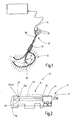
- FIG. 12 illustrates the inventive instrument 11 attached to an endoscope 10 for ablation during the process of mucosal ablation on a stomach 12.
- the endoscope 10 and the instrument 11 are inserted through the esophagus 13 into the interior of the stomach 12.
- Operating elements 14 permit the movement of the endoscope 10 such that, for example, a distal end 15 of the endoscope can be curved in a targeted manner and / or moved along the stomach inner wall, as a result of which different locations of the inner stomach wall can be easily reached.
- the endoscope 10 may include one or more channels 16 (see, for example, FIG Fig. 3a ), in which work equipment such as surgical instruments can be introduced and / or can be supplied or removed via the gaseous and liquid fluids.
- the endoscope 10 may include image transfer means 17 for optically controlling the treatment.
- the Figures 2-4 illustrate the distal end 15 of the endoscope 10 with the attached instrument 11.
- the instrument 11 may be arranged together with the endoscope 10 in a tubular casing 18 having a first lumen 19a for the instrument 11 and a second lumen 19b for the endoscope 10 contains.
- the first and / or the second lumen 19a, b can, as in FIG. 2 and 3 illustrated slotted to facilitate curving of the endoscope 10.
- the tubular sheath 18 may consist of a thin plastic film enclosing the endoscope 10 and the instrument 11 extending through a sheath tube 20 with appropriate play.
- the instrument 11 is preferably formed in the present embodiment as attached to the endoscope 10 outside, along the same extending instrument 11.
- the instrument 11 may, for example, also be designed as an instrument 11 arranged within a channel 16 of the endoscope 10.
- the instrument 11 has a distal instrument end 21 (instrument head) which is preferably movably mounted, preferably movable in the axial direction 22, which coincides with the longitudinal direction of the distal end 15 of the endoscope 10.
- the instrument end 21 can preferably additionally be rotated about the longitudinal axis 23 of the instrument end, for example by +/- 90 °.
- the instrument end 21 may be associated with a socket 24 which is held by the endoscope 10.
- the socket 24 has a passage opening into which the instrument end 21 can be retracted.
- a sheath tube 20 arranged in the second lumen 19b is fixed axially relative to the endoscope 10, for example on the frame 24.
- the sheathing tube 20 is preferably cut helically at its distal end, for example over a length of about 200 mm.
- the casing hose 20 serving as a guide hose preferably at least two gas supply pipe hoses are provided 27a, b arranged to supply gas to the instrument 11.
- the instrument end 21 can be reciprocated in the axial direction 22 by reciprocating the motion transmitting member 25 connected to the instrument head 21.
- a liquid supply line 28 may be guided to the instrument head 21 in the casing hose 20.
- the instrument end 21 is in FIG. 4 illustrated in plan view.
- the instrument end 21 has a connecting element 29 whose task is explained below and which may have a deviating from the circular cross-section.
- the deviations of the cross section of the passage opening of the socket 24 and the shape of the connecting element 29 are such that the connecting element 29 when retracted into the through hole of the socket 24 and thereby rotates in the desired angular position.
- the connecting element 29 may have a circular cross-section at its proximal end 30. It may be formed there, for example, a circular cone. The cross-section of the cone then proceeds gradually from the proximal end 30 towards the distal end 31 FIG. 4 apparent, deviating from the circular shape over, wherein the outer surface of the connecting element 29 is preferably free of steps, which put on the mouth of the through hole of the socket 24 and thus hinder the retraction of the connecting element 29 could.
- the shape of the connecting element 29 and the socket 24 are coordinated so that the connecting element 29 not only in its end position, when it is fully retracted into the socket 24, is fixed in the radial direction, but this orientation substantially maintains until the connecting element 29 completely exits the socket 24.
- the length of the axial displacement wherein the connecting element 29 and thus the end 21 of the instrument 11 substantially retains its position in the radial direction is, for example, 15 mm, preferably 10 mm, particularly preferably 8 mm.
- the connecting element 29 may, for example, be made of ceramic, but preferably of plastic. As related to FIG. 5 is described, the connecting element 29 may in particular be made of a material which is not stable and / or not dimensionally stable at the temperatures prevailing in the plasma region.
- FIGS. 3b and 3c show the arrangement of motion transmission element 25 and gas supply hoses 27a, b with an anti-rotation 32 according to FIGS. 3b and 3c be educated.
- the anti-rotation 32 has for this purpose a protruding shape nose in the form of a spring 33.
- 3d figure shows the socket 24 with a provided in the socket 24 groove 34 on the channel through which the gas supply lines 27a, b and the motion transfer element 25 and the liquid supply line 28 may extend.
- the spring 33 dips into the groove 34 and thus secures the desired position in the extended state of the instrument end 21.
- Figure 3c shows the instrument head 21 in a position in which the instrument head 21 due to the spring 33 in the groove 34 can not be rotated.
- the anti-rotation 32 may, for example, be designed as a plastic extrusion.
- the anti-rotation device 32 may be formed so that it forms an end stop together with the socket 24, which limits the maximum length, which the connecting element 29 and the instrument end 21 can be moved in the axial direction. It is possible to arrange the anti-rotation device 32 at a distance from the holder 24 on the casing hose 20, thereby ensuring the rotational orientation of the connecting element 29 and thus of the instrument end 21 in each axial position. For this purpose, it is then necessary that shortly before leaving the connecting element 29 from the socket 24, the spring 33 already engages in the groove 34 or at least partially engages.
- the anti-rotation device 32 such that the connecting element 29 or the instrument end 21 is held freely movable between its end regions in the direction of rotation.
- rotational fixation of the instrument end 21 is allowed until the connector 29 leaves the socket 24 and again when the spring 33 enters the groove 34.
- the area with a fixed direction of rotation of the instrument end 21 can occupy approximately 15 mm in the areas of its respective end positions. In between, the instrument end 21 can be kept freely movable about 20 mm also in the radial direction.
- FIG. 5 A longitudinal section of an embodiment of the instrument 11 according to the invention FIG. 5 , This may be, for example, in the FIGS. 1 to 4 act instrument 11 act.
- the instrument 11 according to the invention has a first gas supply line 35a and a second gas supply line 35b, which are arranged relative to each other, that the distal Ends 36a, b of the gas supply lines 35a, b with each other an acute angle ⁇ of preferably between a minimum of 1 ° and a maximum of 60 °, more preferably between a minimum of 1 ° and a maximum of 30 °, more preferably 10 ° include so that the ends 36a, b the gas supply lines 35a, b diverge distally.
- the ends 36a, b of the gas supply lines 35a, b have to differently oriented center axes 37a, b, which in FIG. 5 are marked by dash-dotted lines.
- the central axes 37a, b enclose the abovementioned angle ⁇ with one another.
- the ends 36a, b of the gas supply lines 35a, b may be arranged such that their central axes 37a, b lie in a common plane.
- the ends 36a, b of the gas supply lines 35a, b can have a circular cross section or also deviating cross sections, such as an oval cross section, polygonal cross sections, or the like.
- the gas supply lines 35a, b are preferably each formed by a plastic line 38a, b, for example a flexible tube or a tube made of plastic.
- the plastic pipes 38a, b may be end portions of or connected to the gas supply pipe hoses 27a, b.
- the gas supply conduits 35a, b may include ceramic tubes 39a, b, with one ceramic tube 39a, b each in the distal ends 40a, b of the plastic conduits 38a, b.
- the gas supply lines 35a, b serve to supply a gas, in particular an inert gas, for example argon, to the distal end 21 of the instrument 11.
- a gas in particular an inert gas, for example argon
- active gases, aerosols or the like it is also possible to supply active gases, aerosols or the like to which the gas supply lines 35a, b can equally serve.
- At least one first electrode 41a is disposed in the end 36a of the first gas supply pipe 35a, and at least one second electrode 41b is disposed in the end 36b of the second gas supply pipe 35b.
- the electrodes 41a, b are disposed in the distal ends of the ceramic tubes, which in the embodiment form the distal ends 36a, b of the gas supply lines 35a, b.
- the electrodes 41a, b which may be formed of, for example, a refractory metal such as tungsten, are preferably fixed in the ceramic tube 39a, b, respectively.
- the electrodes 41a, b for example, each having resilient portions (not shown), which due to the spring force against the inner surface of the ceramic tube 39a, b, so that the electrodes 41a, b respectively by frictional engagement in the ceramic tube 39a, b are held.
- the electrodes 41a, b are preferably arranged centrally in the openings of the gas supply lines 35a, b and / or oriented along the central axes 37a, b.
- the electrodes 41a, b may be, for example, rod-shaped, spatula-shaped, knife-shaped or needle-shaped.
- the tips of the electrodes 41a, b may be within the gas supply lines 35a, b as it is FIG. 5 suggests, or look out of these.
- the first electrode 41a and the second electrode 41b may form an acute angle with each other, preferably between at least 1 ° and at most 60 °, more preferably between at least 1 ° and at most 30 °, for example 10 °, such that the first electrode and the second electrode 41b Diverge electrode distally.
- the amount of the angle between the electrodes 41a, b may correspond to the amount of the angle a between the ends 36a, b of the gas supply lines 35a, b.
- the distance between the distal tips of the electrodes 41 a, b is preferably several millimeters (eg 3 mm to 12 mm), wherein a Distance of 5 mm to 10 mm, in particular 6.5 mm is particularly advantageous to achieve a uniform, broad-stripe tissue ablation with a homogeneous Ablationstiefe.
- the diameter of the tips of the electrodes 41a, b is preferably in the range of 0.2 mm to 1 mm, wherein in the present embodiment, a diameter of 0.4 mm has been selected. This has proved to be advantageous on the other hand because of the high field strengths which occur due to the small diameter and therefore the good ignitability of the electrodes 41a, b on the one hand and the tissue effects to be achieved therewith.
- the electrodes 41a, b are preferably insulated from each other. Through the gas supply lines 35a, b extend electrical lines 43a, b for supplying the electrodes 41a, b with RF power.
- the plastic lines 38a, b isolate the electrical lines 43a, b respectively against the other electrical line 43a, b.
- the gas supply lines 35a, b with the electrodes 41a, b form plasma probes 44a, b for the electrosurgical treatment of the tissue in front of the instrument 11.
- the ceramic tubes 39a, b preferably protrude distally beyond the ends 40a, b of the plastic leads 38a, b.
- the ends 36a, b of the gas supply lines 35a, b formed of ceramic and thus particularly temperature stable, even during continuous operation of the instrument 11 for large-scale ablation.
- a creepage distance between the electrodes 41a, b may be extended, which improves the dielectric strength of the arrangement. With the ceramic tubes, moreover, the dielectric strength between the electrodes 41a, b can be increased.
- the plastic line 38a, b and, if present, also the ceramic tube 39a, b at the distal end 36a, b of the gas supply line terminate or complete together.
- the plastic lines 38a, b or at least the distal ends 40a, b are preferably made of heat-resistant plastic.
- a free space 45 is arranged between the distal ends 36a, b of the gas supply lines 35a, b which are spread apart at the angle ⁇ , in order to form a splayed instrument head 21.
- the distally widening clearance 45 extends transversely to the direction distally of the distal end 36a of the first gas supply line 35a to the distal end 36b of the second gas supply line 35b.
- the clearance 45 extends between the gas supply conduits 35a, b from the distal ends 36a, b of the gas supply conduits 35a, b proximally to between the proximal ends 46a, b of the ceramic tubes 39a, b.
- the clearance 45 further extends between the gas supply pipes 35a, b from the free distal end portion of the ceramic pipe 39a of the first gas supply pipe 35a to the free distal end portion of the ceramic pipe 39b of the second gas supply pipe 35b.
- the clearance 45 between the gas supply pipes 35a, b extends from the distal portion of the plastic pipe 38a of the first gas supply pipe 35a up to the portion of the plastic pipe 38b of the second gas supply pipe 35b distally protruding from the joint member 29b.
- the instrument 11 provides the user of the instrument 11 with a view between the ends 36a, b of the gas supply lines 35a, b through the ablation region of the plasma probes 44a, b, in particular during the plasma treatment of the tissue with the instrument 11
- the instrument head 21 has a relatively low heat capacity at the distal end, which can become hot when using the plasma probes 44a, b. This allows the instrument 11 to be quickly removed from the patient's body after use. Unwanted tissue adhesions at the end of the instrument may be reduced by the clearance 45.
- the instrument 11 shown has, for arranging the distal ends 36a, b of the gas supply pipes 35a, b with respect to each other so as to include the angle ⁇ , a connecting member 29 with seats 51a, b for the gas supply pipes 35a, b arranged to terminate the ends 36a, b of the gas supply lines 35a, b at the angle ⁇ to fix each other.
- the seats 51a, b preferably indicate the angle ⁇ between the ends 36a, b of the gas supply conduits 35a, b to the arrangement of the ends 36a, b of the gas supply lines 35a, b relative to one another during assembly of the instrument 11 to facilitate.
- the seats 51a, b of the connecting element 50 fastening means for axially fixing the ends 36a, b of the gas supply lines 35a, b.
- the fastening means may comprise means for forming a positive connection and / or means for forming a frictional connection between the gas supply lines 35a, b and the connecting element 29.
- the gas supply lines 35 a, b may be clamped in the connecting element 29.
- the connecting element 29 may alternatively or additionally comprise, for example, snap-locking connection means which cooperate with corresponding means on the gas supply lines 35a, b.
- the gas supply lines 35a, b are axially fixed in the connecting element 29 by means of frictional engagement due to an oversize of the gas supply lines 35a, b.
- the seats 51a, b may define the distances of the ends 36a, b of the gas supply lines 35a, b from each other and / or from the connecting element 29 in order to facilitate the arrangement of the ends 36a, b of the gas supply lines 35a, b during assembly of the instrument 11.
- stops or other positive locking elements may be formed on the connecting element 29 and the gas supply lines 35a, b.
- a modular structure of the instrument 11 can be realized. It can, for example different probes 44a, b, in particular those for plasma coagulation, for example, different types of construction are arranged to each other.
- individual probes 44a, b which can be used separately from the instrument 11, in particular outside the seat 51a, b in the connecting element 29 (individual probes), can be arranged relative to the instrument 11.
- the distal ends of the individual probes 44a, b are thereby arranged fixed to one another at the acute angle a, which is preferably predetermined by the seats 51a, b of the connecting element 50, and preferably at a distance from one another.
- one or both plasma probes 44a, b are interchangeable without destroying the connecting element 29 and / or without having to dismantle the plasma probe 44a, b to be replaced.
- the plasma probes 44a, b connected to the connecting element can preferably be removed from the connecting element 29, respectively, in order to load another plasma probe 44a, b into the instrument 11.
- the functionality of the removed plasma probe 44a, b is preferably maintained during the removal.
- connecting element 29 preferably tapers in the proximal direction. This results in a particularly slim construction of the connecting element 50 and thus of the instrument head 21.
- the clearance 45 between the distal ends 36a, b of the gas supply lines 35a, b preferably extends proximally at least to the distal end 31 of the connecting element 50.
- the in FIG. 5 shown connecting member 29 has at its distal end 31 two spread at an angle ⁇ arranged extensions 53 a, b, which may be, for example tubular or tubular, wherein the gas supply lines 35a, b extend through the extensions 53a, b.
- the extensions 53a, b form separate channels in the connecting element 29, through which the gas supply lines 35a, b for arranging the ends 36a, b of the gas supply lines 35a, b at the angle ⁇ and preferably for axial fixation by means of frictional engagement.
- the central axes of the straight extensions 53a, b enclose the angle ⁇ with each other and thereby define the angle ⁇ between the ends 36a, b of the gas supply lines 35a, b.
- the clearance 45 extends from between the distal ends 36a, b of the gas supply conduits 35a, b, proximally between the extensions 53a, b, such that the user passes between the projections through the one extension 53a to the other extension 53b Free space 45 can look at the tissue.
- the connecting element 29 whose plastic conduit wall between each ceramic tube 39a, b and connecting element 29 is clamped.
- the inner and outer diameter of the plastic conduits 38a, b may be widened at the distal end 40a, b of the plastic conduit 38a, b opposite a portion in front of the distal end 40a, b of the plastic conduit 38a, b to receive the ceramic tube 39a, b.
- the extension can be formed by pressing the ceramic tube 39a, b into the end 40a, b of the plastic line 38a, b.
- the straight ceramic tubes 39a, b extending from the distal end 36a, b of the gas supply lines 35a, b into the connecting element 29, b contribute to a steady flow of gas through the ends 36a, b of the gas supply lines 35a, b.
- the gas flow area in the ceramic tube 39a, b and the gas flow area of the plastic tubing 38a, b proximal before extension are preferably the same.
- the gas supply lines 35a, b in the connecting element 29 transversely to the longitudinal extent of the gas supply lines 35a, b preferably arranged spaced from each other.
- the gas supply lines 35a, b are preferably arranged in the connecting element 29 such that sections 56a, b of the gas supply lines 35a, b, in the exemplary embodiment of the plastic lines 38a, b, within the connecting element 29 in front of the distal ends 36a, b of the gas supply lines 35a, b include an angle greater than the angle a between the ends 36a, b of the gas supply lines 35a, b, a distance of the ends 36a, b of the gas supply lines 35a, b from each other and thus a width of the space 45 regardless of the angle a between the ends 36a, b of the gas supply lines 35a, b to provide.
- the gas supply lines 35a, b diverge in a section in the connecting element 29 in front of the distal ends 36a, b of the gas supply lines 35a, b distally correspondingly more first and then less. This results in a slim arrangement of the gas supply lines 35a, b before the sections.
- this space for a head 60 another probe, such as a liquid jet probe 61 may be created.
- the head 60 of the further probe and the liquid supply line 28 are in FIG. 5 not shown cut.
- the plastic lines 38a, b preferably extend uninterrupted through the connecting element 29.
- the plastic lines 38a, b isolate the electrical lines 43a, b respectively against the connecting element 29th
- the ends 36a, b of the gas supply lines 35a, b are distal over the distal end 31 of the connecting element 29, in the illustrated embodiment via the extensions 53a, b, over.
- the connecting element 29, which is disposed proximally with respect to the distal ends of the plasma probes 44a, b, is spaced from the zone at the distal ends 36a, b of the gas supply lines 35a, b with increased temperature.
- the connecting element 29 can therefore be made of a material which does not withstand the temperatures prevailing in the zone during the plasma treatment.
- the material for the connecting element 29 is, for example, plastic, such as PEEK, PA or elastomer, such as silicone, into consideration.
- the electrodes 41 a, b are preferably arranged outside the connecting element 29, spaced from the distal end 31 of the connecting element 29. Creepage distances between the electrodes 41a, b via the connecting element 29 are therefore particularly long.
- the mentioned further probe 61 which may have the instrument 11 in addition to the plasma probes 44a, b, is in FIG FIG. 5 in a rest position and in FIG. 6 shown in a working position advanced beyond the distal ends of the plasma probes 44a, b.
- the displaceability of the further probe 61 is indicated by the double arrow 62.
- the further probe 61 may be, for example, a liquid jet probe for applying aqueous NaCl solution under the mucosa to lift the mucosa. With this, a liquid jet can be formed with a pressure or flow required, for example, for injecting the mucosa.
- the liquid jet probe 61 has at its head 60 at the distal end of the liquid jet probe to a nozzle with an outlet opening through which a liquid, for example sodium chloride solution, for example, can be ejected as a jet.
- a liquid for example sodium chloride solution
- the further probe is preferably held in a seat 65 of the connecting element 29 that is separate from the seats of the gas supply lines.
- the further probe 61 is preferably slidably guided in the seat 65 in the direction of distal or proximal relative to the connecting element 29.
- the further probe 61 may be fixed in the seat 65 with respect to the connecting member 29, so that movement of the head 60 of the further probe 61 with respect to the connecting member 29 is not possible.
- the further probe 61 is preferably slidably guided in the distal direction such that the central axis 66 of the further probe 61 lies above an imaginary line connecting the centers of the openings of the gas supply lines 35a, b.
- the extending in the direction of leadership Central axis of the sliding seat 65 in the connecting member 29 for the further probe 61 is preferably arranged above an imaginary, oriented transversely to the guide direction line from the center axis of the seat 51a for the first gas supply line 35a to the central axis of the seat 51b for the second gas supply line 35b. This is also in the FIG. 5 and FIG. 6 illustrated embodiment of the case showing the instrument 11 from below.
- the head 60 of the further probe 61 can be distally relative to the arrangement of the ends 36a , b gas supply lines 35a, b are moved to the mentioned working position and the head 60 of the further probe 61 are moved back relative to the arrangement in the direction proximally in the aforementioned rest position.
- the further probe 61 is preferably arranged such that the head 60 of the further probe 61 can be displaced distally beyond the distal ends of the plasma probes 44a, b into the working position by the clearance 45 arranged between the ends 36a, b of the gas supply lines 35a, b and that the head 60 of the further probe 61 can be moved back through the free space 45 to a rest position proximally in front of the free space 45.
- a stop element for example, as shown in Figures 5 and 6 formed by the relative to the liquid supply line widened head 60, respectively be that prevents too far retraction of the head 60 of the further probe 61 proximally beyond the rest position.
- the head 60 of the liquid jet probe 61 When the head 60 of the liquid jet probe 61 is displaced distally beyond the ends of the plasma probes 44a, b, the head 60 of the liquid jet probe 61 can be placed on the tissue to inject NaCl solution into the tissue through the nozzle in the head 60. without at the same time the distal ends of the plasma probes 44a, b touch the tissue. If the head 60 of the further probe 61 is retracted to the rest position proximally in front of the clearance 45, the user has a further improved view of the ablation area.
- a cleaning element (not shown) may be arranged, with the tissue adhesions or other contaminants from the plasma probes 44a, b can be deported.
- FIG. 6 also shows an example of an elongate motion transmitting member 67, which is tensile, compression and torsional stiff, but easily bendable, and a displacement (arrow 68) of the instrument head 21 back and forth with respect to the distal end 15 of the endoscope 10 and a Turning (arrow 69) about an axis along the instrument 11 allowed.
- the motion transmission element 67 is for transmitting the movement with the connecting element 29 and a control element 14 (s. FIG. 1 ) connected.
- the motion transmission element 67 can be, for example, a metal coil, preferably electrically insulated.
- the electrical leads 43a, b for supplying the electrodes 41a, b with RF power via a switch arrangement 75 to an electrical source 76, for example in the form of a high-frequency generator 77.
- This provides an RF voltage of several hundred kilohertz (for example 350 kHz) and a suitable voltage above 1000 Vp (eg between a minimum of 4 kVp and a maximum of 6 kVp, preferably 4.3 kVp or 4.9 kVp).
- the RF generator 77 can apply a power of more than 100 W (for example, 120 W).
- the voltage is provided relative to a zero potential to which the patient is connected via at least one neutral electrode 78.
- This neutral electrode 78 is attached over a large area at a suitable location of the patient's body.
- the switch assembly 75 connects the leads 43a, b and thus the electrodes 41a, b alternately, i. alternately with the output of the high-frequency generator 77.
- the switching frequency with which the electrodes 41a, b are alternately activated is in the range of a few Hz, preferably between 1 Hz and 20 Hz, preferably 5 Hz.
- the gas supply lines 35a, b can be acted upon together with a gas flow of, for example, at least 1 liter / minute to a maximum of 4 liters / minute, preferably 2 liters / minute.
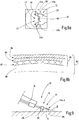
- FIG. 8a shows an image 80, which is received by means of the means 17 for image transmission in the endoscope 10.
- the instrument head 21 With the connecting element 29 and the ends of the plasma probes 44a, b and also a tissue area 47 illuminated by the illumination means on the endoscope 10.
- tissue region 47 there is a tissue site 81 which is to be treated with the instrument 11.
- the head 60 of the liquid jet probe 61 is retracted proximally from the free space 45 to a rest position.
- the spread-shaped instrument head 21 offers a clear view of the tissue site 81 due to the clearance 45 between the ends of the plasma probes 44a, b and the extensions 53a, b through the clearance 45. This facilitates the safe and rapid guidance of the instrument 11 considerably.
- the instrument 11 for ablation described so far works as follows: For planar ablation of the mucosa, for example for the therapeutic treatment of diseased tissue changes, for influencing the weight and eating behavior of patients or for other therapeutic reasons, the endoscope 10 provided with the instrument 11 for ablation becomes according to FIG. 1 introduced through the esophagus 13 of the patient in the stomach 12. By means of the control elements 14 of the endoscope 10 whose distal end 15 is positioned at the desired ablation site so that the tissue site to be treated is in the field of view of the endoscope 10.
- the distal end 21 of the ablation instrument 11 is then slightly advanced by appropriately pushing the arrangement of sheath tube and gas supply line tubes 13 and / or the motion transfer element 67 so that it is at the desired distance, for example 3 mm to the mucosa 84.
- the plasma jets 83a, b can combine to form a fan-shaped jet.
- the plasma jets 83a, b strike the mucosa 84 side by side and coagulate their uppermost layer, in particular their epithelium 85 and the lamina Propria 86 and parts of the submucosa 87.
- the Muscularis Propria 88 is preferably spared by the previously formed fluid cushion.
- the width of the fabric strip may be greater than 10 mm, and in some cases approximately 14 mm, due to the angular arrangement of the ends 36a, b of the gas supply lines 35a, b and the electrodes 41a, b.
- the treatment proceeds by the user by means of the controls 14 of the endoscope 10 and by appropriate guidance of the motion transmitting member 25, the instrument end 21 along a path, in particular transversely to an imaginary line connecting the electrodes 41 a, b, at a distance to the tissue across the mucosa 84, leaving a coagulated strip of tissue about 12 mm to 20 mm wide.
- the mucosa 84 can be coagulated with great reliability with reduced risk of muscular ice damage.
- the instrument 11 may have a sliding member 90 which is positioned fixed to the instrument so that the instrument 11 rests on the tissue 80 via the sliding member 90.
- FIG. 9 shows, highly schematically, an embodiment of the system 91, which has a trained example of the above description and held on an endoscope 10 instrument 11, which, as indicated by a dashed line, ⁇ is guided over the fabric 80 at an acute angle.
- the sliding element 90 of the instrument 11 can, as shown, be fastened to the connecting element 29 or, for example, to the distal ends of the plasma probes 44a, b.
- the sliding element 90 is preferably arranged on the instrument 11 such that the instrument 11 preferably rests on the tissue 80 via the sliding element 90 proximally in front of the treatment site.
- the sliding element 90 slides on the tissue, and if a maximum angle ⁇ between the longitudinal axis of the distal instrument end 21 and the tissue 80 is not exceeded, the ends of the plasma probes 44a, b are at a certain minimum distance a , or if a certain angle between instrument end and tissue is maintained, at a certain distance a guided over the tissue become.
- the sliding element 90 thus promotes the homogeneity of the ablation.
- the angle ⁇ between the longitudinal axis of the distal instrument end 21 and the tissue when passing over the tissue is preferably between more than 0 ° and 80 °, more preferably at least 20 ° to a maximum of 30 °.
- the distance a or the minimum distance a (in FIG.
- tissue 80 sliding member 90 is preferably more than 0 mm to preferably not more than 10 mm, especially preferably more than 0 mm to a maximum of 5 mm, for example more than 0 mm to a maximum of 3 mm.
- FIG. 10a shows an exemplary embodiment of the instrument 11 with a connecting element 29, the two ceramic tube sections 92a, b stuck in the distal ends 36a, b of the gas supply lines 35a, b.
- the ceramic pipe sections 92a, b are interconnected by a connecting bracket 93 and aligned with each other by the connecting bracket 93 at the acute angle ⁇ , so that the ends 36a, b of the gas supply lines 35a, b are aligned at the acute angle ⁇ .
- the electrodes 41a, b and the electric wires 43a, b are illustrated by a solid line inside the gas supply pipes 35a, b.
- the bracket 93 extends arcuately transversely to the longitudinal axis of the instrument 11 under the ceramic pipe sections 92a, b.
- the connecting bracket 93 also serves as a sliding element 90 for the instrument 11.
- FIG. 10c shows a modification of the embodiment of the instrument 11 according to FIG. 10b with another Connecting bracket 93 which connects the ceramic pipe sections and extends arcuately transversely to the longitudinal axis over the ceramic pipe sections 92a, b.
- a shoe 90 is arranged, which serves as a sliding element.
- the connecting element 29 of one of the embodiments described herein may be in one or more parts.
- the connecting element 29 may be formed such that separately usable plasma probes 44a, b (individual probes) are each fastened to a connecting element part, wherein the connecting element parts, if needed for an instrument 11 according to the invention, are fastened to each other and the individual probes 44a, b with it the instrument 11 with the angle ⁇ and the space 45 between the distal ends of the plasma probes 44a, b are arranged.
- an instrument 11 which can be used in particular for large-area tissue treatment, in an example for ablation of the mucosa 84, wherein the instrument 11 has at least one first gas supply line 35a and at least one second gas supply line 35b, the distal ends 36a, b thereof are arranged to enclose an acute angle ⁇ such that the ends 36a, b of the gas supply lines 35a, b diverge distally to distally divergent when gas is applied to the gas supply lines 35a, b Gas flows in the distal ends 36a, b of the gas supply lines 35a, b to produce.
- a clearance 45 Arranged between the distal ends 36a, b of the gas supply lines 35a, b is a clearance 45 which allows the user of the instrument 11 through the clearance 45 between the distal ends 36a, b of the gas supply lines 35a, b to the tissue area 47 behind the distal To look at the end 21 of the instrument 11.
- the clearance 45 is preferably open in the distal direction. Due to the acute angle ⁇ , a wide plasma jet can be generated by means of electrodes 41a, b arranged at least partially in the ends 36a, b of the gas supply lines 35a, b, with which the mucosa ablation can be carried out. In this case, the instrument 11 can be guided particularly accurately due to the view through the space 45.
- a connecting element 29 is provided.
- the connecting element 29 may have free-standing extensions 53a, b at its distal end 31, through which the gas supply lines 35a, b extend.
- the distal ends 36a, b of the gas supply lines 36a, b are preferably free-standing, extending away from the connecting element 29.
Description
Die Erfindung betrifft eine Vorrichtung zur Ablation, insbesondere für die Mucosaablation.The invention relates to a device for ablation, in particular for mucosa ablation.
Das in
Die therapeutische Mucosaablation, zum Beispiel zur Tumorablation oder zur Zerstörung von das Essverhalten beeinflussenden Zellen der Magenwand vorteilhafterweise zur Gewichtsreduktion, wird typischerweise durch endoskopische Intervention durchgeführt, wobei zur Ablation spezielle Sonden zur Anwendung kommen können.Therapeutic mucosa ablation, for example, for tumor ablation or destruction of gastric wall-influencing cells, advantageously for weight loss, is typically performed by endoscopic intervention, with special probes for ablation.
Beispielsweise ist dazu aus der
Aus der
Die großflächige Mucosaablation stellt an den Behandler insbesondere Herausforderungen hinsichtlich Geduld und Fingerfertigkeit. Dies insbesondere, wenn dazu für den allgemeinen Gebrauch vorgesehene flexible Instrumente, wie Polypektomieschlingen oder dergleichen eingesetzt werden. Mit solchen Schlingen wird in einem Arbeitsschritt lediglich eine Resektion der Mucosa von ca. 2 cm2 ausgeführt. Im Fundus- und Cardiabereich des Magens ist eine Resektion mithilfe eines flexiblen Endoskops sehr schwierig. Außerdem besteht das Risiko der Perforation.The large-area mucosa ablation places particular demands on the dentist with regard to patience and dexterity. This is especially true when flexible instruments such as polypectomy snares or the like intended for general use are used. With such loops only a resection of the mucosa of about 2 cm 2 is performed in one step. In the fundic and cardiac area of the stomach, resection using a flexible endoscope is very difficult. There is also the risk of perforation.
Bei einer Ablation der Mucosa ist eine nicht ausreichende Ablation ebenso abzulehnen wie eine zu tiefe Einwirkung, weil dadurch darunter liegende Gewebeschichten beschädigt werden könnten bis hin zur Perforation des Magens. Insgesamt ist eine zügige und sichere Durchführung der Behandlung wünschenswert. Zudem ist eine unerwünschte thermische Belastung des Gewebes im gesamten Behandlungsverlauf zu vermeiden.In case of mucosal ablation, inadequate ablation should be rejected, as well as excessive impact, as this could damage underlying tissue layers and even perforate the stomach. Overall, a speedy and safe implementation of the treatment is desirable. In addition, an undesirable thermal stress on the tissue throughout the course of treatment should be avoided.
Die der Erfindung zugrunde liegende Aufgabe wird mit dem Instrument nach Anspruch 1 gelöst.The object underlying the invention is achieved with the instrument according to claim 1.
Das erfindungsgemäße Instrument ist zur großflächigen Gewebebehandlung, vorzugsweise zur Gewebeablation, beispielsweise zur Mucosaablation, geeignet. Das erfindungsgemäße Instrument weist wenigstens eine erste Gaszuführungsleitung und eine zweite Gaszuführungsleitung auf, wobei die Gaszuführungsleitungen der Zuführung eines Gases, bevorzugt einem Inertgas, insbesondere Argon, dienen. Eine erste Elektrode ist wenigstens teilweise in der ersten Gaszuführungsleitung angeordnet. Eine zweite Elektrode ist wenigstens teilweise in der zweiten Gaszuführungsleitung angeordnet. Die erste Gaszuführungsleitung und die zweite Gaszuführungsleitung sind relativ zueinander derart angeordnet, dass das distale Ende der ersten Gaszuführungsleitung mit dem distalen Ende der zweiten Gaszuführungsleitung einen spitzen Winkel einschließt, so dass die distalen Enden der Gaszuführungsleitungen in distaler Richtung divergieren. Auf Grund des spitzen Winkels können bei Beaufschlagung der Gaszuführungsleitungen mit Gas in dem Ende der ersten Gaszuführungsleitung eine Gasströmung und in dem Ende der zweiten Gaszuführungsleitung eine Gasströmung erzeugt werden, wobei die Strömungsrichtungen der beiden Gasströmungen den spitzen Winkel einschließen. Der Winkel beträgt vorzugsweise zwischen mindestens 1° und maximal 60°, besonders bevorzugt zwischen mindestens 1° und maximal 30°, beispielsweise 10°. Die erste Elektrode und die zweite Elektrode können miteinander ebenfalls einen spitzen Winkel, beispielsweise von demselben Betrag, einschließen, so dass die erste Elektrode und die zweite Elektrode in distaler Richtung divergieren. Die erste Gaszuführungsleitung und die zweite Gaszuführungsleitung sind zueinander derart angeordnet, dass zwischen dem distalen Ende der ersten Gaszuführungsleitung und dem distalen Ende der zweiten Gaszuführungsleitung ein Freiraum angeordnet ist. Dieser erlaubt einen Blick zwischen den Enden der Gaszuführungsleitungen hindurch auf den Einwirkungsbereich des Instruments vor den distalen Enden der Gaszuführungsleitungen.The instrument according to the invention is suitable for large-area tissue treatment, preferably for tissue ablation, for example for mucosa ablation. The instrument according to the invention has at least a first gas supply line and a second gas supply line, wherein the gas supply lines of the supply of a gas, preferably an inert gas, in particular argon serve. A first electrode is at least partially disposed in the first gas supply line. A second electrode is at least partially disposed in the second gas supply line. The first gas supply line and the second gas supply line are arranged relative to each other such that the distal end of the first gas supply line forms an acute angle with the distal end of the second gas supply line so that the distal ends of the gas supply lines diverge distally. Due to the acute angle, gas flow may be produced in the end of the first gas supply line when the gas supply lines with gas are pressurized, and gas flow in the end of the second gas supply line, the flow directions of the two gas streams enclosing the acute angle. The angle is preferably between at least 1 ° and a maximum of 60 °, more preferably between at least 1 ° and a maximum of 30 °, for example 10 °. The first electrode and the second electrode may also subtend an acute angle, for example, of the same amount, such that the first electrode and the second electrode diverge distally. The first gas supply line and the second gas supply line are arranged to each other such that a free space is arranged between the distal end of the first gas supply line and the distal end of the second gas supply line. This allows a view between the ends of the gas supply lines to the area of action of the instrument in front of the distal ends of the gas supply lines.
Wenn die Elektroden mit einer HF-Spannung versorgt werden, kann mittels an den Elektroden erzeugten Funken ein Plasma, beispielsweise ein Argon-Plasma erzeugt werden. Das Plasma kann zu einer Behandlung des vor den Elektroden liegenden Gewebes herangezogen werden. Die Behandlung umfasst insbesondere schneiden und/oder koagulieren. Durch die Anordnung der Enden der Gaszuführungsleitungen zueinander im spitzen Winkel und/oder durch die Anordnung der Elektroden zueinander im spitzen Winkel kann erreicht werden, dass die von den beiden Enden der Gaszuführungsleitungen ausgehenden Plasmaströme divergieren und einen breiten streifenförmigen Bereich in der Mucosa schneiden und/oder koagulieren, wenn das Instrument entlang der Mucosa bewegt wird. Die aus den beiden Enden der Gaszuführungsleitungen austretenden Plasmaströme können gemeinsam einen etwa fächerförmigen Strom bilden, d.h. einen Strahl mit nichtkreisförmigem (ovalem oder streifenartigem) Querschnitt. Die Austrittsöffnungen der beiden Gaszuführungsleitungen liegen vorzugsweise auf einer Linie, die quer zur Bewegungsrichtung des Instruments orientiert ist. Bei geeigneter Festlegung des Winkels zwischen den beiden Enden der Gaszuführungsleitungen und/oder zwischen den beiden Elektroden sowie der Ausströmgeschwindigkeit des Gases aus den Gaszuführungsleitungen, der Gasmenge sowie der elektrischen Beaufschlagung der beiden Elektroden, kann erreicht werden, dass sich über die Breite des koagulierten Streifens der Mucosa eine einheitlichere, im therapeutischen Sinne einheitliche Wirkungstiefe ergibt. Damit lässt sich eine gleichmäßige und großflächige Gewebebehandlung, insbesondere -ablation, erreichen.When the electrodes are supplied with an RF voltage, a plasma, for example an argon plasma, can be generated by means of sparks generated at the electrodes. The plasma can be used to treat the tissue lying in front of the electrodes. The treatment includes, in particular, cutting and / or coagulating. By arranging the ends of the gas supply lines to each other at an acute angle and / or by the arrangement of the electrodes at an acute angle to each other can be achieved that diverge from the two ends of the gas supply lines plasma streams and cut a broad strip-shaped area in the mucosa and / or coagulate as the instrument is moved along the mucosa. The plasma streams emerging from the two ends of the gas supply lines can together form an approximately fan-shaped stream, ie a jet with a non-circular (oval or strip-like) cross-section. The outlet openings of the two gas supply lines are preferably on a line which is oriented transversely to the direction of movement of the instrument. With a suitable definition of the angle between the two ends of the gas supply lines and / or between the two electrodes and the outflow velocity of the gas from the gas supply lines, the amount of gas and the electrical loading of the two electrodes, can be achieved that across the width the coagulated strip of the mucosa results in a more uniform, in therapeutic sense uniform depth of action. This makes it possible to achieve uniform and extensive tissue treatment, in particular ablation.
Das erfindungsgemäße Konzept ebnet den Weg zu der Gestaltung eines besonders schmalen, schlanken Instrumentenendes das kaum breiter oder im Einzelfall auch schmaler sein kann als die von ihm erzeuge Spur koagulierten Mucosagewebes.The inventive concept paves the way to the design of a particularly narrow, slender end of the instrument that can hardly be wider or, in some cases, narrower than the trace of coagulated mucosal tissue produced by it.
Durch den Freiraum zwischen den Enden der Gaszuführungsleitungen hat der Benutzer des Instruments eine verbesserte Sicht auf den Einwirkungsbereich des Instruments vor den distalen Enden der Gaszuführungsleitungen bzw. vor den Enden der Elektroden. Mit dem Freiraum ist dem Verwender des Instruments vorzugsweise die Möglichkeit gegeben, bei der plasmachirurgischen Behandlung von Gewebe mit dem Instrument schräg zur Längsachse des distalen Endes des Instruments zwischen den distalen Enden der Gaszuführungsleitungen hindurch durch den Freiraum auf den Einwirkungsbereich des Instruments blicken zu können.Due to the clearance between the ends of the gas supply lines, the user of the instrument has an improved view of the area of action of the instrument in front of the distal ends of the gas supply lines or in front of the ends of the electrodes. With the clearance, the user of the instrument is preferably given the opportunity to look at the plasma treatment of tissue with the instrument obliquely to the longitudinal axis of the distal end of the instrument between the distal ends of the gas supply lines through the space on the sphere of action of the instrument.
Zudem ist durch den Freiraum die Wärmekapazität des Instruments an dem distalen Ende des Instruments relativ gering. Wenn das Ende des Instruments durch die Plasmabehandlung heiß wird, kann ein schnelleres Abkühlen des Endes des Instruments erreicht werden, so dass das Instrument relativ kurze Zeit nach der Plasmabehandlung aus dem Körper des Patienten entfernt werden kann, ohne dass die Gefahr einer Verletzung gesunden Gewebes durch ein heißes Ende des Instruments besteht. Durch das in dem Freiraum "fehlende" Material kommt es dort zu keiner Gewebeanhaftung auf Grund heißen Materials.In addition, the heat capacity of the instrument at the distal end of the instrument is relatively low due to the free space. When the end of the instrument becomes hot due to the plasma treatment, a faster cooling of the end of the instrument can be achieved, so that the instrument can be removed from the body of the patient relatively short time after the plasma treatment without the risk of injury to healthy tissue There is a hot end of the instrument. Due to the "missing" material in the free space, tissue adhesion does not occur there hot material.
Das Verbindungselement für das erfindungsgemäße Instrument weist einen Sitz für die erste Gaszuführungsleitung und einen Sitz für die zweite Gaszuführungsleitung auf. Die Sitze sind derart ausgebildet, dass die Gaszuführungsleitungen in den Sitzen so angeordnet werden können, dass die distalen Enden der Gaszuführungsleitungen, wie beschrieben, miteinander einen spitzen Winkel einschließen, so dass die Gaszuführungsleitungen an ihren distalen Enden in distaler Richtung divergieren. Die Sitze sind vorzugsweise derart ausgebildet, dass diese einen bestimmten Betrag des Winkels zwischen den Enden der Gaszuführungsleitungen vorgeben. Zudem sind die Sitze dazu eingerichtet, dass die Gaszuführungsleitungen in den Sitzen derart angeordnet werden können, dass zwischen dem distalen Ende der ersten Gaszuführungsleitung und dem distalen Ende der zweiten Gaszuführungsleitung der Freiraum angeordnet ist, der eine Sicht zwischen den Enden der Gaszuführungsleitungen hindurch auf das Gewebe vor den distalen Enden der Gaszuführungsleitungen gestattet.The connecting element for the instrument according to the invention has a seat for the first gas supply line and a seat for the second gas supply line. The seats are configured such that the gas supply lines in the seats can be arranged such that the distal ends of the gas supply lines form an acute angle with each other as described so that the gas supply lines diverge distally at their distal ends. The seats are preferably designed such that they predetermine a certain amount of the angle between the ends of the gas supply lines. In addition, the seats are arranged so that the gas supply lines in the seats can be arranged such that between the distal end of the first gas supply line and the distal end of the second gas supply line, the free space is arranged, which provides a view between the ends of the gas supply lines to the tissue allowed in front of the distal ends of the gas supply lines.
Die Sitze des Verbindungselements können Mittel zum axialen Fixieren der Gaszuführungsleitungen in dem Verbindungselement aufweisen. Die Sitze können dazu bspw. Formschlussverbindungsmittel, wie etwa einen oder mehrere Anschläge oder Mittel zur Ausbildung einer Schnapp-RastVerbindung und/oder Mittel zur Ausbildung einer Reibschlussverbindung zwischen der Gaszuführungsleitung und dem Verbindungselement aufweisen. Vorzugsweise sind die Sitze dazu eingerichtet, einen bestimmten Betrag des Abstands der Enden der Gaszuführungsleitungen zueinander und/oder in Bezug auf das distale Ende des Verbindungselements vorzugeben. Vorzugsweise sind die Verbindungsmittel dazu eingerichtet, dass die Verbindung zwischen einer Gaszuführungsleitung und dem Verbindungselement hergestellt und/oder gelöst werden kann, während keine Verbindung und/oder eine Verbindung zwischen der anderen Gaszuführungsleitung und dem Verbindungselement hergestellt ist.The seats of the connecting element may have means for axially fixing the gas supply lines in the connecting element. For example, the seats may have interlocking connection means, such as one or more stops or means for forming a snap-latch connection and / or means for forming a frictional connection between the gas supply line and the connection element. Preferably, the seats are adapted to set a certain amount of the distance of the ends of the gas supply lines to each other and / or with respect to the distal end of the connecting element. Preferably, the connection means are adapted to be able to establish and / or release the connection between a gas supply line and the connection element while no connection and / or connection is established between the other gas supply line and the connection element.
Der Freiraum zwischen den distalen Enden der Gaszuführungsleitungen ist vorzugsweise quer zur Richtung distal beidseitig offen, um von außerhalb des Instruments zwischen den Enden der Gaszuführungsleitungen hindurch auf den Bereich des Gewebes vor dem Instrument blicken zu können. Alternativ oder zusätzlich erstreckt sich der Freiraum vorzugsweise von dem distalen Ende der ersten Gaszuführungsleitung bis zum dem distalen Ende der zweiten Gaszuführungsleitung. Alternativ oder zusätzlich verbreitert sich der Freiraum vorzugsweise zwischen den Gaszuführungsleitungen in Richtung distal. Der Freiraum kann sich in Richtung distal beispielsweise in dem spitzen Winkel verbreitern, den das distale Ende der ersten Gaszuführungsleitung mit dem distalen Ende der zweiten Gaszuführungsleitung einschließt.The space between the distal ends of the gas supply lines is preferably open distally on both sides transversely to the direction in order to be able to look at the area of the tissue in front of the instrument from outside the instrument between the ends of the gas supply lines. Alternatively or additionally, the free space preferably extends from the distal end of the first gas supply line to the distal end of the second gas supply line. Alternatively or additionally, the free space preferably widens distally between the gas supply lines. The clearance may widen distally, for example, at the acute angle that the distal end of the first gas supply conduit encloses with the distal end of the second gas supply conduit.
In einem System ist das erfindungsgemäße Instrument außen an einem Endoskop befestigt. Das Endoskop kann bspw. einen Arbeitskanal aufweisen, wobei das Instrument vorzugsweise außerhalb des Arbeitskanals angeordnet ist. Das Instrument kann außen an dem Endoskop geführt sein. Dadurch kann das Instrument beispielsweise entlang der Achse des distalen Endes des Endoskops verschoben werden. An dem distalen Ende des Endoskops kann eine Lichtquelle zum Beleuchten des Gewebes vor dem Instrument und/oder ein Eingang für eine ein Bild zu dem proximalen Ende des Endoskops übertragende Einrichtung (Bildleiter) aufweisen. Das Instrument kann an dem Endoskop derart angeordnet sein, dass der Benutzer mit Hilfe des Bildleiters zwischen den Enden der Gaszuführungsleitungen hindurch auf das Gewebe vor dem Instrument blicken kann.In a system, the instrument according to the invention is attached to the outside of an endoscope. The endoscope may, for example, have a working channel, the instrument preferably being arranged outside the working channel. The instrument can be guided on the outside of the endoscope. This allows the instrument to be displaced, for example, along the axis of the distal end of the endoscope. At the distal end of the endoscope, a light source for illuminating the tissue in front of the instrument and / or an input for an image to the proximal Have end of the endoscope transmitting device (image guide). The instrument may be disposed on the endoscope such that the user may look at the tissue in front of the instrument through the image conductor between the ends of the gas supply lines.
Eine Verschiebbarkeit des distalen Endes des Instruments zur Ablation in Axialrichtung, d.h. in Längsrichtung des Endoskops, erleichtert die Handhabung insbesondere bei der Ablation von Gewebeschichten in großen Hohlorganen, wie beispielsweise Ablation der Mucosa im Magen. Das distale Ende des Instruments kann zum Beispiel zwischen 0 mm und 100 mm ausgefahren werden, wobei eine Ausfahrbarkeit bis 50 mm als vorteilhaft, weiter werden 30mm Ausfahrlänge als optimal angesehen.A displaceability of the distal end of the instrument for ablation in the axial direction, i. in the longitudinal direction of the endoscope, facilitates handling especially in the ablation of tissue layers in large hollow organs, such as ablation of the mucosa in the stomach. The distal end of the instrument can be extended, for example, between 0 mm and 100 mm, with an extendability of up to 50 mm being considered advantageous, further 30 mm extension length being considered optimal.
Es wird als besonders vorteilhaft angesehen, wenn eine dem Verbindungselement zugeordnete, an dem Endoskop befestigte Fassung eine zu einem unrunden Querschnitt des Verbindungselements komplementäre Ausnehmung aufweist, in die das Verbindungselement bei Rückzug in proximaler Richtung einfahren kann. Der unrunde Querschnitt kann insbesondere an dem distalen Ende des Verbindungselements ausgebildet sein. Das Verbindungselement bzw. das Instrumentenende wird dadurch in der Fassung in seiner Drehbeweglichkeit eingeschränkt. Dies erleichtert die Handhabung des erfindungsgemäßen Ablationsinstruments erheblich. Insbesondere kann sichergestellt werden, dass das Verbindungselement bzw. das Instrumentenende durch Rückzug in einer bestimmten Drehlage angeordnet ist, die es auch nach dem Ausschieben beibehalten kann. Das Verbindungselement bzw. das Instrumentenende kann vorzugsweise auch in dem ausgefahrenen Zustand z.B. durch eine Erhebung am Schlauch am proximalen Ende der Fassung und eine dafür vorgesehene Nut in eine gewünschte Lage gebracht werden.It is considered to be particularly advantageous if a connection, which is assigned to the connecting element and is fastened to the endoscope, has a recess which is complementary to a non-circular cross-section of the connecting element and into which the connecting element can retract in the proximal direction when retracted. The non-circular cross section may be formed in particular at the distal end of the connecting element. The connecting element or the instrument end is thereby limited in the version in its rotational mobility. This considerably facilitates the handling of the ablation instrument according to the invention. In particular, it can be ensured that the connecting element or the instrument end is arranged by retraction in a specific rotational position, which it can maintain even after pushing out. The connecting element or the instrument end can preferably also in the extended state, for example be brought by a survey on the tube at the proximal end of the socket and a designated groove in a desired position.
Das erfindungsgemäße Instrument, das Verbindungselement, das System sowie das Verfahren können mit einem oder mehreren der hierin beschriebenen Merkmale weiter gebildet werden.The instrument, fastener, system, and method of the invention may be further formed with one or more of the features described herein.
Die erste Gaszuführungsleitung und die erste Elektrode können zu einer ersten Sonde und die zweite Gaszuführungsleitung und die zweite Elektrode können zu einer anderen zweiten Sonde gehören, wobei die Sonden dazu eingerichtet sein können, dass diese getrennt, unabhängig von der jeweils anderen Sonde zur Plasmabehandlung verwendet werden können. Die erste Sonde und die zweite Sonde können mit dem Verbindungselement derart gehalten werden, dass das distale Ende der Gaszuführungsleitung der ersten Sonde mit dem distalen Ende der Gaszuführungsleitung der zweiten Sonde den spitzen Winkel einschließt, und sodass zwischen dem distalen Ende der ersten Gaszuführungsleitung und dem distalen Ende der zweiten Gaszuführungsleitung der Freiraum angeordnet ist.The first gas supply line and the first electrode may belong to a first probe and the second gas supply line and the second electrode may belong to another second probe, wherein the probes may be arranged to be used separately, independently of the other probe for the plasma treatment can. The first probe and the second probe may be held with the connector such that the distal end of the gas supply line of the first probe encloses the acute angle with the distal end of the gas supply line of the second probe, and between the distal end of the first gas supply line and the distal end End of the second gas supply line of the free space is arranged.
Wenigstens eine der Sonden ist mit dem Verbindungselement in dem Instrument vorzugsweise auswechselbar befestigt oder in der Anordnung befestigbar. Auf diese Weise kann der Benutzer eine oder mehrere der mittels des Verbindungselements zu einem Instrument angeordneten Sonden gegen eine von dem Benutzer gewünschte Sonde austauschen.At least one of the probes is preferably interchangeably attached or attachable to the connector in the instrument. In this way, the user can exchange one or more of the probes arranged by means of the connecting element for an instrument with a probe desired by the user.
In dem erfindungsgemäßen Instrument können die Enden der Gaszuführungsleitungen distal über das Verbindungselement überstehen. Das Verbindungselement kann dadurch bei einer Behandlung mit Hilfe des Instruments außerhalb eines Bereichs erhöhter Temperatur, bspw. außerhalb eines Bereichs mit einer Temperatur angeordnet sein, die die Temperatur übersteigt bis zu der das Material, aus dem das Verbindungselement besteht, beständig ist. Die Sitze des Verbindungselements für die Gaszuführungsleitungen können derart ausgebildet sein, dass diese die Position einer Gaszuführungsleitung in dem Instrument bezüglich der anderen Gaszuführungsleitung festlegen. Die Sitze können entsprechend einen distalen Überstand der Enden der Gaszuführungsleitungen über das distale Ende des Verbindungselements festlegen. Die Elektroden sind vorzugsweise außerhalb des Verbindungselements angeordnet. Dies kann die thermische Belastung des Verbindungselements vermindern. Durch diese Maßnahme und/oder eine proximal vor dem Ende der Gaszuführungsleitungen zurückgesetzte Anordnung des Verbindungselements kann das Verbindungselement aus Material hergestellt sein, das eine relativ geringe thermische Belastbarkeit aufweist. Mit der Anordnung der Elektroden außerhalb des Verbindungselements kann auch eine Vermeidung von Kriechströmen zwischen den Elektroden über das Verbindungselement getroffen sein. Die Gefahr von Spannungsüberschlägen ist damit vermindert.In the instrument according to the invention, the ends of the gas supply lines may extend distally over the connecting element survive. The connection element can thereby be arranged outside the range of elevated temperature, for example, outside a region having a temperature which exceeds the temperature up to which the material of which the connection element is made, when treated with the aid of the instrument. The seats of the connecting element for the gas supply lines may be formed such that they determine the position of a gas supply line in the instrument with respect to the other gas supply line. The seats may correspondingly define a distal projection of the ends of the gas supply lines via the distal end of the connecting element. The electrodes are preferably arranged outside the connecting element. This can reduce the thermal load of the connecting element. By this measure and / or a proximally set back before the end of the gas supply lines arrangement of the connecting element, the connecting element may be made of material having a relatively low thermal capacity. With the arrangement of the electrodes outside the connecting element can also be made to avoid leakage currents between the electrodes via the connecting element. The risk of flashovers is thus reduced.
Als Material für das Verbindungselement kommt beispielsweise Keramik oder Kunststoff, wie beispielsweise PEEK, PA, oder Elastomer, wie etwa Silikon, in Frage.As a material for the connecting element, for example, ceramic or plastic, such as PEEK, PA, or elastomer, such as silicone in question.
Die erste Gaszuführungsleitung weist vorzugsweise eine Kunststoffleitung auf, die sich von proximal vor dem Verbindungselement durch das Verbindungselement bis distal hinter das Verbindungselement unterbrechungsfrei erstreckt. Genauso weist die zweite Gaszuführungsleitung vorzugsweise eine Kunststoffleitung auf, die sich von proximal vor dem Verbindungselement durch das Verbindungselement bis distal hinter das Verbindungselement unterbrechungsfrei erstreckt. Wenn in den Gaszuführungsleitungen elektrischen Leitungen für die HF-Versorgung der Elektroden geführt sind, so sind diese in den Kunststoffleitungen von dem Verbindungselement und/oder gegeneinander vorzugsweise elektrisch isoliert. Zudem ist die Gefahr von Leckagen in den Gaszuführungsleitungen innerhalb des Verbindungselements mit unerwünschtem Austritt von Gas vermindert, wenn die Gaszuführungsleitungen gesondert von dem Verbindungselement sind, also die Gaszuführungsleitungen nicht abschnittsweise von dem Verbindungselement gebildet sind.The first gas supply line preferably has a plastic line which extends from proximal in front of the connecting element through the connecting element to distally without interruption behind the connecting element. Likewise, the second gas supply line preferably has a plastic line, which extends from proximal in front of the connecting element through the connecting element to distally without interruption behind the connecting element. If electrical lines for the RF supply of the electrodes are guided in the gas supply lines, they are preferably electrically insulated in the plastic lines from the connecting element and / or against each other. In addition, the risk of leakage in the gas supply lines within the connecting element with undesired escape of gas is reduced if the gas supply lines are separate from the connecting element, ie the gas supply lines are not formed in sections of the connecting element.
Die Gaszuführungsleitungen sind zumindest an ihren distalen Enden vorzugsweise aus einem hitzebeständigen Kunststoff oder Keramik ausgebildet. Dies ermöglicht Dauerbetrieb der Ablationsvorrichtung, insbesondere zum Abtragen größerer Bereiche der Mucosa.The gas supply lines are preferably formed of a heat-resistant plastic or ceramic at least at their distal ends. This allows for continuous operation of the ablation device, especially for ablation of larger areas of the mucosa.
Vorzugsweise weist die erste Gaszuführungsleitung an ihrem distalen Ende ein Keramikrohr auf und die zweite Gaszuführungsleitung weist an ihrem distalen Ende vorzugsweise ein Keramikrohr auf. Die distalen Enden der Gaszuführungsleitungen können damit besonders hitzebeständig ausgebildet sein. Zudem sind mit den Keramikrohren gebildeten Enden der Gaszuführungsleitungen besonders steif.Preferably, the first gas supply line has a ceramic tube at its distal end, and the second gas supply line preferably has a ceramic tube at its distal end. The distal ends of the gas supply lines can thus be made particularly heat resistant. In addition, formed with the ceramic tubes ends of the gas supply lines are particularly stiff.
Die erste Gaszuführungsleitung und/oder die zweite Gaszuführungsleitung kann an ihrem distalen Ende beispielsweise ein Keramirohr aufweisen, das in einer Kunststoffleitung, beispielsweise einem Kunststoffrohr oder einem Kunststoffschlauch, der Gaszuführungsleitung steckt. Die Keramikrohre können mit ihren distalen Enden aus den Kunststoffleitungen distal herausschauen, so dass die Gaszuführungsleitungen an ihren distalen Enden jeweils durch das Keramikrohr gebildet sind. Auf Grund der entsprechend gegenüber dem distalen Ende der Keramikrohre in proximaler Richtung zurückgesetzt angeordneten distale Enden der Kunststoffleitungen sind die Enden der Gaszuführungsleitungen besonders hitzebeständig. Die distalen Enden der Keramikrohre stehen an den Enden der Gaszuführungsleitungen vorzugsweise distal über die distalen Enden der Kunststoffleitungen um einen Betrag gerade so über, dass die thermische Belastung der distalen Enden der Kunststoffleitungen beim elektrochirurgischen Betrieb des Instruments ein vorgegebenes Maß, beispielsweise eine bestimmte Temperatur, nicht überschreitet. Das distale Ende des Kunststoffschlauchs bzw. des Kunststoffrohrs ist vorzugsweise außerhalb einer Temperaturzone an dem distalen Ende der Gaszuführungsleitung am Rand der Temperaturzone angeordnet, wobei in der Temperaturzone beim elektrochirurgischen Betrieb des Instruments eine Temperatur herrscht, die die Temperatur bis zu der die Kunststoffleitung beständig ist, übersteigt.The first gas supply line and / or the second gas supply line may have at its distal end, for example, a ceramic tube in a plastic line, such as a plastic tube or a plastic tube, the gas supply line is inserted. The ceramic tubes can with their distal ends of the plastic lines distally look out, so that the gas supply lines are formed at their distal ends respectively through the ceramic tube. Due to the fact that the distal ends of the plastic lines are set back in the proximal direction relative to the distal end of the ceramic tubes, the ends of the gas supply lines are particularly heat-resistant. The distal ends of the ceramic tubes preferably extend distally beyond the distal ends of the plastic conduits at the ends of the gas supply conduits by an amount such that the thermal stress on the distal ends of the plastic conduits does not reach a predetermined level, such as a certain temperature, during electrosurgical operation of the instrument exceeds. The distal end of the plastic tube or the plastic tube is preferably arranged outside a temperature zone at the distal end of the gas supply line at the edge of the temperature zone, wherein in the temperature zone during electrosurgical operation of the instrument a temperature prevails, which is the temperature up to which the plastic line is resistant, exceeds.
Die Kunststoffleitungen bestehen vorzugsweise aus einem Material mit antihaftender, vorzugsweise glatter, Oberfläche, z.B. PTFE, um Gewebeanhaftungen zu vermeiden. Über die distalen Enden der Kunststoffleitungen überstehende Bereiche der Keramikrohre können eine nachbearbeitete Oberfläche aufweisen oder mit einer Antihaftbeschichtung versehen sein, um Gewebeanhaftungen zu vermeiden.The plastic conduits are preferably made of a material having a non-stick, preferably smooth, surface, e.g. PTFE to avoid tissue buildup. Protruding regions of the ceramic tubes projecting beyond the distal ends of the plastic conduits may have a reworked surface or be provided with a non-stick coating in order to avoid tissue adhesions.
Die erste und zweite Elektrode sind vorzugsweise in den Keramikrohren angeordnet und darin befestigt. Die Enden der Elektroden können distal aus den Keramikrohren herausschauen oder innerhalb der Keramikrohre angeordnet sein.The first and second electrodes are preferably disposed in the ceramic tubes and fixed therein. The ends The electrodes may be distally out of the ceramic tubes or located within the ceramic tubes.
Vorzugsweise sind die Keramikrohre mit ihren proxima-len Enden in dem Verbindungselement angeordnet. Dies trägt zur Stabilität der Anordnung der Enden der Gaszuführungsleitungen bei. Die Keramikrohre können beispielsweise in dem Verbindungselement stecken, um die Wände der Kunststoffleitungen zumindest an dem distalen Ende des Verbindungselements jeweils zwischen Keramikrohr und Verbindungselement einzuklemmen, um die Gaszuführungsleitungen axial in dem Verbindungselement zu fixieren.Preferably, the ceramic tubes are arranged with their proximal ends in the connecting element. This contributes to the stability of the arrangement of the ends of the gas supply lines. For example, the ceramic tubes may be stuck in the connecting member to clamp the walls of the plastic leads at least at the distal end of the connecting member between the ceramic tube and the connecting member, respectively, to fix the gas supply leads axially in the connecting member.
Das Instrument kann eine weitere Sonde, beispielsweise eine Fluidstrahlsonde, insbesondere eine Flüssigkeitsstrahlsonde, aufweisen. Die weitere Sonde kann relativ zu der Anordnung der ersten Gaszuführungsleitung und der zweiten Gaszuführungsleitung bis auf höchstens einen Freiheitsgrad relativ zu der Anordnung fixiert angeordnet sein. Die weitere Sonde kann in einem Sitz des Verbindungselements für die weitere Sonde angeordnet sein. Bevorzugt ist, die weitere Sonde relativ zu der Anordnung der ersten Gaszuführungsleitung und der zweiten Gaszuführungsleitung in und/oder aus dem Freiraum in distaler Richtung verschiebbar. Das weitere Instrument kann beispielsweise in einem Sitz des Verbindungselements verschiebbar geführt sein. Besonders bevorzugt ist die weitere Sonde über das distale Ende der Plasmabehandlungseinheit des Instruments hinaus distal verschiebbar. Das distale Ende der weiteren Sonde kann somit auf das Gewebe aufgesetzt werden, ohne dass die distalen Ende der Gaszuführungskanäle und/oder die Elektroden auf das Gewebe aufgesetzt werden müssen. Das distale Ende des weiteren Instruments kann vorzugsweise in proximaler Richtung hinter die distalen Enden der Gaszuführungskanäle zurückgezogen werden, um eine Sicht auf noch weitere Bereiche des Gewebes zwischen den Enden der Gaszuführungsleitungen hindurch zu gestatten. Zudem ist das distale Ende der weiteren Sonde in einer solchen Ruhestellung thermisch weniger belastet.The instrument may comprise a further probe, for example a fluid jet probe, in particular a liquid jet probe. The further probe may be arranged fixed relative to the arrangement of the first gas supply line and the second gas supply line to at most one degree of freedom relative to the arrangement. The further probe can be arranged in a seat of the connecting element for the further probe. Preferably, the further probe is displaceable relative to the arrangement of the first gas supply line and the second gas supply line in and / or out of the free space in the distal direction. The further instrument may, for example, be displaceably guided in a seat of the connecting element. Particularly preferably, the further probe is distally displaceable beyond the distal end of the plasma treatment unit of the instrument. The distal end of the further probe can thus be placed on the tissue without the distal end of the gas supply channels and / or the electrodes having to be placed on the tissue. The distal end of the further instrument may preferably be in the proximal direction Direction behind the distal ends of the gas supply channels are withdrawn to allow a view of still further areas of the tissue between the ends of the gas supply lines. In addition, the distal end of the further probe is thermally less stressed in such a rest position.
Zur Erleichterung der Handhabung des Instruments kann das Instrument ein Gleitelement zum Führen des Instruments über das Gewebe aufweisen. Das Gleitelement kann beispielsweise an dem Verbindungselement befestigt sein. Das Gleitelement ist derart an dem erfindungsgemäßen Instrument angeordnet, so dass das Gleitelement bei der Anwendung des erfindungsgemäßen Instruments zwischen dem Gewebe und dem Instrument angeordnet ist. Das Gleitelement ist derart angeordnet, dass das erfindungsgemäße Instrument bei der Anwendung des Instruments über das Gleitelement auf dem Gewebe, beispielsweise proximal vor dem Einwirkungsbereich des Instruments, aufliegen kann. Die distalen Enden der Plasmasonden können damit in einem festgelegten Abstand von dem Gewebe, beispielsweise mit einem Abstand zwischen 0-10mm, bevorzugt von 0-5mm, besonders bevorzugt 0-3mm, über das Gewebe geführt werden. Der Winkel zwischen der Längsachse des distalen Instrumentenendes und dem Gewebe beträgt dabei bevorzugt zwischen 0° und 80°, besonders bevorzugt zwischen 20° und 30°.To facilitate handling of the instrument, the instrument may include a slider for guiding the instrument over the tissue. The sliding element may for example be fastened to the connecting element. The sliding element is so arranged on the instrument according to the invention, so that the sliding element is arranged in the application of the instrument according to the invention between the tissue and the instrument. The sliding element is arranged in such a way that the instrument according to the invention can rest on the tissue during the application of the instrument via the sliding element, for example proximally in front of the impact area of the instrument. The distal ends of the plasma probes can thus be guided over the tissue at a defined distance from the tissue, for example with a distance between 0-10 mm, preferably 0-5 mm, particularly preferably 0-3 mm. The angle between the longitudinal axis of the distal end of the instrument and the tissue is preferably between 0 ° and 80 °, particularly preferably between 20 ° and 30 °.
Das erfindungsgemäße Instrument ist vorzugsweise ein monopolares Instrument. Dies bedeutet, dass in diesem Fall die Neutralelektrode nicht an dem Instrument vorgesehen ist, sondern großflächig an dem Patienten befestigt wird. Der Strom fließt dabei nicht über das Instrument sondern über den Körper des Patienten in die Neutralelektrode ab.The instrument according to the invention is preferably a monopolar instrument. This means that in this case the neutral electrode is not provided on the instrument, but is attached over a large area to the patient. The current does not flow through the instrument but into the neutral electrode via the patient's body.
Die beiden Elektroden an dem distalen Ende des Instruments sind vorzugsweise elektrisch gegeneinander isoliert und an gesonderte Zuleitungen zur Versorgung der Elektroden mit HF-Leistung angeschlossen. Die Zuleitungen sind bevorzugt durch die Gaszuführungsleitungen geführt.The two electrodes at the distal end of the instrument are preferably electrically isolated from each other and connected to separate leads for supplying the electrodes with RF power. The supply lines are preferably guided through the gas supply lines.
Bei der Verwendung des erfindungsgemäßen Instruments werden die beiden Elektroden bevorzugt gepulst mit HF-Leistung beaufschlagt. Besonders bevorzugt werden die Elektroden bei Verwendung des erfindungsgemäßen Instruments abwechselnd mit elektrischer Leistung beaufschlagt, wodurch sich ein besonders gleichmäßiger Ablationseffekt und eine über die Breite des erzeugten Ablationsstreifens gemessen einheitliche Koagulationstiefe erreichen lässt. Dies insbesondere, wenn an den beiden Elektroden alternierend hochfrequente Spannung im Bereich mehrerer Hundert Kilohertz anliegt, wobei die Umschaltfrequenz (Alternierungsfrequenz) zwischen beiden Elektroden wenige Hertz beträgt. Die an die Elektroden abgegebene Leistung kann beispielsweise zwischen 10 W und 400W, insbesondere zwischen 80 W und 120 W betragen.When using the instrument according to the invention, the two electrodes are preferably pulsed with RF power applied. Particularly preferably, the electrodes are alternately applied with the use of the instrument according to the invention with electrical power, whereby a particularly uniform ablation effect and a measured over the width of the ablation strip generated uniform coagulation can be achieved. This is particularly the case if alternating high-frequency voltage in the range of several hundred kilohertz is applied to the two electrodes, wherein the switching frequency (alternating frequency) between the two electrodes is a few hertz. The power delivered to the electrodes may, for example, be between 10 W and 400 W, in particular between 80 W and 120 W.
Bei der Verwendung des erfindungsgemäßen Instruments kann bspw. mit der Fluidstrahlsonde vor der thermischen Ablation der Mucosa Flüssigkeit, beispielsweise NaCl-Lösung, in die Magenwand so eingebracht werden, dass sich unter der gewünschten Ablationsstelle ein Flüssigkeitskissen bildet. Die Mündung der Fluidstrahlsonde kann daraufhin vorzugsweise in proximaler Richtung hinter das distale Ende der Anordnung von Plasmasonden zurückgezogen werden.When using the instrument according to the invention, for example with the fluid jet probe before the thermal ablation of the mucosa, liquid, for example NaCl solution, can be introduced into the stomach wall in such a way that a fluid cushion forms below the desired ablation point. The mouth of the fluid jet probe can then be retracted, preferably in the proximal direction, behind the distal end of the array of plasma probes.
Weitere Einzelheiten vorteilhafter Ausführungsformen der Erfindung sind Gegenstand der nachfolgenden Beschreibung sowie der Zeichnungen.Further details of advantageous embodiments The invention are the subject of the following description and the drawings.
Es zeigen schematisch:
-
Figur 1 - ein erfindungsgemäßes Instrument an einem Endoskop im Einsatz in schematischer Darstellung, -
Figur 2 - ein Ende eines Systems mit einem Endoskop und einem daran angeordneten erfindungsgemäßen Instrument zur Ablation in ausschnittsweiser Seitenansicht, -
Figur 3a, 3b, 3c - das Endoskop mit dem Ablationsinstrument nachFigur 2 in perspektivischer Ansicht, -
Figur 3d - die Fassung für das Instrument gemäßFigur 3a-c in einer Ansicht auf das proximale Ende der Fassung, -
Figur 4 - das Endoskop und das Ablationsinstrument nachFigur 2 und3 in Stirnansicht, -
Figur 5 - ein Beispiel eines erfindungsgemäßen Ablationsinstruments in ausschnittsweiser Schnittdarstellung, -
Figur 6 - das erfindungsgemäße Ablationsinstrument nachFigur 5 in ausschnittsweiser Draufsicht, -
Figur 7 - die elektrische Beschaltung des Ablationsinstruments als Schaltschema, -
Figur 8a - eine Darstellung eines Blicks durch einen Bildleiter eines Endoskops auf ein erfindungsgemäßes Instrument und den Behandlungsbereich, -
Figur 8b - eine schematische Darstellung des Aufbaus einer Magenwand, -
Figur 9 - eine stark schematische Darstellung eines erfindungsgemäßen Instruments an einem Endoskop, -
Figur 10a, b, c - ein Ausführungsbeispiel des erfindungsgemäßen Instruments.
-
FIG. 1 - An inventive instrument on an endoscope in use in a schematic representation, -
FIG. 2 one end of a system with an endoscope and an ablation device according to the invention arranged thereon in a sectional side view, -
Figure 3a, 3b, 3c - the endoscope with the ablation instrument behindFIG. 2 in perspective view, -
3d figure - the version for the instrument according toFigure 3a-c in a view of the proximal end of the socket, -
FIG. 4 - the endoscope and the ablation instrument behindFIG. 2 and3 in front view, -
FIG. 5 an example of an ablation instrument according to the invention in a sectional illustration in section, -
FIG. 6 - The ablation instrument according to the inventionFIG. 5 in a sectional plan view, -
FIG. 7 - the electrical wiring of the ablation instrument as a circuit diagram, -
FIG. 8a - An illustration of a view through an image guide of an endoscope on an inventive instrument and the treatment area, -
FIG. 8b a schematic representation of the structure of a stomach wall, -
FIG. 9 a highly schematic representation of an instrument according to the invention on an endoscope, -
FIG. 10a, b, c - An embodiment of the instrument according to the invention.
In
Die
Das Instrument 11 ist im vorliegenden Ausführungsbeispiel bevorzugt als an dem Endoskop 10 außen angebrachtes, sich längs desselben erstreckendes Instrument 11 ausgebildet. Alternativ kann das Instrument 11 beispielsweise auch als innerhalb eines Kanals 16 des Endoskops 10 angeordnetes Instrument 11 ausgebildet sein. Das Instrument 11 weist ein distales Instrumentenende 21 (Instrumentenkopf) auf, das vorzugsweise beweglich gelagert, vorzugsweise in Axialrichtung 22 beweglich ist, die mit der Längsrichtung des distalen Endes 15 des Endoskops 10 übereinstimmt. Das Instrumentenende 21 kann vorzugsweise zusätzlich um die Längsachse 23 des Instrumentenendes, um beispielsweise +/-90°, gedreht werden. Dem Instrumentenende 21 kann eine Fassung 24 zugeordnet sein, die von dem Endoskop 10 gehalten ist. Die Fassung 24 weist eine Durchgangsöffnung auf, in die das Instrumentenende 21 eingefahren werden kann.The
Ein in dem zweiten Lumen 19b angeordneter Ummantelungsschlauch 20 ist axial relativ zu dem Endoskop 10, beispielsweise an der Fassung 24, fixiert. Der Ummantelungsschlauch 20 ist an seinem distalen Ende vorzugsweise spiralförmig eingeschnitten, z.B. über eine Länge von etwa 200 mm. In dem als Führungsschlauch dienenden Ummantelungsschlauch 20 sind vorzugsweise wenigstens zwei Gaszuführungsleitungsschläuche 27a,b zur Gasversorgung des Instruments 11 angeordnet. Zudem ist in dem Ummantelungsschlauch 20 vorzugsweise ein längliches Bewegungsübertragungselement 25, z.B. eine Metallwendel, angeordnet, das zum Verschieben und Drehen des Instrumentenkopfes 21 dient. Das Instrumentenende 21 kann beispielsweise in Axialrichtung 22 hin und her bewegt werden, indem das mit dem Instrumentenkopf 21 verbundene Bewegungsübertragungselement 25 hin- und her bewegt wird. In dem Ummantelungsschlauch 20 kann zusätzlich eine Flüssigkeitszuführungsleitung 28 zu dem Instrumentenkopf 21 geführt sein.A
Das Instrumentenende 21 ist in
Um dies zu bewirken, kann das Verbindungselement 29 an seinem proximalen Ende 30 einen Kreisquerschnitt aufweisen. Es kann dort beispielsweise ein Kreiskegel ausgebildet sein. Der Querschnitt des Kegels geht dann ausgehend von dem proximalen Ende 30 in Richtung des distalen Endes 31 allmählich in die aus
Diese Bauform trägt erheblich zur Handhabungserleichterung des Instruments 11 bei. Wird das Instrumentenende 21 bzw. das Verbindungselement 29 so weit aus der dem Verbindungselement 29 zugeordneten Fassung 24 herausgeschoben, so dass lediglich noch das proximale Ende 30 des Verbindungselements 29 in der Fassung 24 steht oder dass das Verbindungselement 29 ganz aus der Fassung 24 herausgeschoben ist, kann das Ende 21 des Instruments 11 über ein Drehen des Bewegungsübertragungselements 25 in verschiedene Winkelpositionen gedreht werden. Wird das Ende 21 des Instruments 11 jedoch zurückgezogen, findet das Verbindungselement 29 in die Fassung 24 ein, die das Verbindungselement 29 und damit das Instrumentenende 21 in die vorgegebene Winkelposition dreht. Die Überführung des Instrumentenendes 21 bzw. des Verbindungselements 29 in die in
Das Verbindungselement 29 kann bspw. aus Keramik, vorzugsweise aber aus Kunststoff bereitgestellt sein. Wie im Zusammenhang mit
Um die Orientierung des Instrumentenendes 21 in radialer Richtung sicherzustellen, wenn das Verbindungselement 29 in axialer Richtung soweit bewegt worden ist, dass es aus der Fassung 24 austritt, kann die Anordnung aus Bewegungsübertragungselement 25 und Gas zuführungsleitungsschläuchen 27a,b mit einer Verdrehsicherung 32 gemäß
Die Verdrehsicherung 32 kann bspw. als Kunststoffumspritzung ausgeführt sein. Die Verdrehsicherung 32 kann so ausgebildet sein, dass sie zusammen mit der Fassung 24 einen Endanschlag bildet, der die maximale Länge begrenzt, die das Verbindungselement 29 bzw. das Instrumentenende 21 in axialer Richtung bewegt werden kann. Es ist möglich, die Verdrehsicherung 32 in einem Abstand zur Fassung 24 an dem Ummantelungsschlauch 20 anzuordnen, so dass dadurch die Rotationsorientierung des Verbindungselements 29 und damit des Instrumentenendes 21 in jeder Axialposition sichergestellt ist. Dazu ist es dann erforderlich, dass kurz vor dem Verlassen des Verbindungselements 29 aus der Fassung 24 die Feder 33 bereits in die Nut 34 eingreift oder wenigstens teilweise eingreift.The anti-rotation 32 may, for example, be designed as a plastic extrusion. The
Es ist auch möglich, die Verdrehsicherung 32 so anzuordnen, dass das Verbindungselement 29 bzw. das Instrumentenende 21 zwischen seinen Endbereichen in Rotationsrichtung frei beweglich gehalten ist. Bei solch einer beispielhaften Anordnung ist eine Rotationsfixierung des Instrumentenendes 21 so lange gewährt, bis das Verbindungselement 29 die Fassung 24 verlässt, und dann wieder, wenn die Feder 33 in die Nut 34 eintritt. Bei einer gesamten Axialbewegung des Verbindungselements 29 bzw. des Instrumentenendes 21 von bspw. 50 mm kann der Bereich mit fixierter Rotationsrichtung des Instrumentenendes 21 in den Bereichen seiner jeweiligen Endlagen jeweils ca. 15 mm einnehmen. Dazwischen kann das Instrumentenende 21 ca. 20 mm auch in radialer Richtung frei beweglich gehalten sein.It is also possible to arrange the
Eine längsgeschnittene Darstellung eines Ausführungsbeispiels des erfindungsgemäßen Instruments 11 zeigt
Die Enden 36a,b der Gaszuführungsleitungen 35a,b können einen Kreisquerschnitt oder auch abweichende Querschnitte, wie einen Ovalquerschnitt, Mehreckquerschnitte, oder dergleichen, aufweisen. Die Gaszuführungsleitungen 35a,b werden vorzugsweise jeweils durch eine Kunststoffleitung 38a,b, z.B. ein flexibles Rohr oder einen Schlauch aus Kunststoff, gebildet. Die Kunststoffleitungen 38a,b können Endabschnitte der Gaszuführungsleitungsschläuche 27a,b sein oder an diese angeschlossen sein. Zusätzlich zu den Kunststoffleitungen 38a,b können zu den Gaszuführungsleitungen 35a,b Keramikrohre 39a,b gehören, wobei jeweils ein Keramikrohr 39a,b in den distalen Enden 40a,b der Kunststoffleitungen 38a,b steckt. Die Gaszuführungsleitungen 35a,b dienen der Zuführung eines Gases, insbesondere eines Inertgases, beispielsweise Argon, an das distale Ende 21 des Instruments 11. Es können jedoch auch Aktivgase, Aerosole oder dergleichen zuzuführen sein, wozu die Gaszuführungsleitungen 35a,b gleichermaßen dienen können.The ends 36a, b of the
In dem Ende 36a der ersten Gaszuführungsleitung 35a ist wenigstens eine erste Elektrode 41a angeordnet und in dem Ende 36b der zweiten Gaszuführungsleitung 35b ist wenigstens eine zweite Elektrode 41b angeordnet. In dem dargestellten Ausführungsbeispiel sind die Elektroden 41a,b in den distalen Enden der Keramikrohre angeordnet, die im Ausführungsbeispiel die distalen Enden 36a,b der Gaszuführungsleitungen 35a,b bilden. Die Elektroden 41a,b, die beispielsweise aus einem hitzebeständigen Metall, wie Wolfram, ausgebildet sein können, sind vorzugsweise jeweils in dem Keramikrohr 39a,b befestigt. Dazu können die Elektroden 41a,b beispielsweise jeweils federnd bildende Abschnitte (nicht dargestellt) aufweisen, die sich auf Grund der Federkraft gegen die Innenfläche des Keramikrohrs 39a,b stemmen, so dass die Elektroden 41a,b jeweils durch Reibschluss in dem Keramikrohr 39a,b gehalten sind. Die Elektroden 41a,b sind vorzugsweise mittig in den Öffnungen der Gaszuführungsleitungen 35a,b angeordnet und/oder längs zu den Mittelachsen 37a,b orientiert. Die Elektroden 41a,b können beispielsweise stab-, spatel-, messer- oder nadelförmig sein. Die Spitzen der Elektroden 41a,b können innerhalb der Gaszuführungsleitungen 35a,b liegen, wie es
Die Elektroden 41a,b sind vorzugsweise gegeneinander isoliert. Durch die Gaszuführungsleitungen 35a,b erstrecken sich elektrische Leitungen 43a,b zur Versorgung der Elektroden 41a,b mit HF-Leistung. Die Kunststoffleitungen 38a,b isolieren die elektrischen Leitungen 43a,b jeweils gegen die andere elektrische Leitung 43a,b. Die Gaszuführungsleitungen 35a,b mit den Elektroden 41a,b bilden Plasmasonden 44a,b zur elektrochirurgischen Behandlung des Gewebes vor dem Instrument 11.The
Die Keramikrohre 39a,b stehen vorzugsweise distal über die Enden 40a,b der Kunststoffleitungen 38a,b hervor. Auf diese Weise sind die Enden 36a,b der Gaszuführungsleitungen 35a,b aus Keramik gebildet und damit besonders temperaturstabil, auch bei Dauerbetrieb des Instruments 11 zur großflächigen Ablation. Außerdem kann damit eine Kriechstrecke zwischen den Elektroden 41a,b verlängert sein, was die Spannungsfestigkeit der Anordnung verbessert. Mit den Keramikrohren kann außerdem die Durchschlagfestigkeit zwischen den Elektroden 41a,b erhöht sein.The
Alternativ zu der in
Zwischen den in dem Winkel α gespreizt angeordneten distalen Enden 36a,b der Gaszuführungsleitungen 35a,b ist ein Freiraum 45 angeordnet, um einen gespreizt gabelförmigen Instrumentenkopf 21 zu bilden. Der sich in Richtung distal verbreiternde Freiraum 45 erstreckt sich quer zur Richtung distal bzw. proximal von dem distalen Ende 36a der ersten Gaszuführungsleitung 35a bis zum dem distalen Ende 36b der zweiten Gaszuführungsleitung 35b. Der Freiraum 45 erstreckt sich zwischen den Gaszuführungsleitungen 35a,b von den distalen Enden 36a,b der Gaszuführungsleitungen 35a,b proximal bis zwischen die proximalen Enden 46a,b der Keramikrohre 39a,b. In dem in
Durch den Freiraum 45 bietet das Instrument 11 dem Benutzer des Instruments 11 eine Sicht zwischen den Enden 36a,b der Gaszuführungsleitungen 35a,b hindurch auf den Ablationsbereich der Plasmasonden 44a,b, insbesondere während der Plasmabehandlung des Gewebes mit dem Instrument 11. Insbesondere kann der Benutzer von außerhalb des Instruments 11, beispielsweise mit Hilfe eines Mittels 17 zur Bildübertragung an oder in dem Endoskop 10, an dem das Instrument 11 angeordnet sein kann, zwischen den Spitzen der Plasmasonden 44a,b durch den Freiraum 45 hindurch auf den Gewebebereich 47 (s. auch
Das in
Um die Enden 36a,b der Gaszuführungsleitungen 35a,b so zu fixieren, dass diese einen festen Abstand voneinander aufweisen, weisen die Sitze 51a,b des Verbindungselements 50 Befestigungsmittel zur axialen Fixierung der Enden 36a,b der Gaszuführungsleitungen 35a,b auf. Die Befestigungsmittel können Mittel zur Ausbildung einer Formschlussverbindung und/oder Mittel zur Ausbildung einer Reibschlussverbindung zwischen den Gaszuführungsleitungen 35a,b und dem Verbindungselement 29 aufweisen. Die Gaszuführungsleitungen 35a,b können in dem Verbindungselement 29 festgeklemmt sein. Das Verbindungselement 29 kann alternativ oder zusätzlich beispielsweise Schnapp-Rast-Verbindungsmittel aufweisen, die mit entsprechenden Mitteln an den Gaszuführungsleitungen 35a,b zusammenwirken. In dem in
Die Sitze 51a,b können die Abstände der Enden 36a,b der Gaszuführungsleitungen 35a,b voneinander und/oder von dem Verbindungselement 29 vorgeben, um die Anordnung der Enden 36a,b der Gaszuführungsleitungen 35a,b beim Zusammenbau des Instruments 11 zu erleichtern. Zur Festlegung des Abstands können beispielsweise Anschläge oder sonstige Formschlusselemente an dem Verbindungselement 29 und den Gaszuführungsleitungen 35a,b ausgebildet sein.The
Durch das Verbindungselement 29 kann ein modularer Aufbau des Instruments 11 verwirklicht sein. Es können beispielsweise verschiedene Sonden 44a,b, insbesondere solche zur Plasmakoagulation, beispielsweise unterschiedlicher Bauformen zueinander angeordnet werden. Mit dem Verbindungselement 29 können einzelne Sonden 44a,b, die jeweils, gesondert von dem Instrument 11, insbesondere außerhalb des Sitzes 51a,b in dem Verbindungselement 29, verwendbar sind (Einzelsonden), zu dem Instrument 11 angeordnet werden. Die distalen Enden der Einzelsonden 44a,b werden dadurch zueinander in dem spitzen Winkel a, der von den Sitzen 51a,b des Verbindungselements 50 vorzugsweise vorgegeben ist, und vorzugsweise in einem Abstand voneinander fixiert angeordnet. Vorzugsweise sind eine oder beide Plasmasonden 44a,b auswechselbar ohne das Verbindungselement 29 zerstören und/oder ohne die auszuwechselnde Plasmasonde 44a,b zerlegen zu müssen. Die mit dem Verbindungselement verbundenen Plasmasonden 44a,b können vorzugsweise jeweils aus dem Verbindungselement 29 entnommen werden, um eine andere Plasmasonde 44a,b in das Instrument 11 einzuwechseln. Die Funktionsfähigkeit der entnommenen Plasmasonde 44a,b bleibt bei der Entnahme vorzugsweise erhalten.By the connecting
Das in
Der Freiraum 45 zwischen den distalen Enden 36a,b der Gaszuführungsleitungen 35a,b erstreckt sich vorzugsweise proximal wenigstens bis zu dem distalen Ende 31 des Verbindungselements 50. Das in
In dem in
Wie in
Wie dargestellt erstrecken sich die Kunststoffleitungen 38a,b vorzugsweise unterbrechungsfrei durch das Verbindungselement 29. Die Kunststoffleitungen 38a,b isolieren die elektrischen Leitungen 43a,b jeweils gegen das Verbindungselement 29.As illustrated, the
Die Enden 36a,b der Gaszuführungsleitungen 35a,b stehen distal über das distale Ende 31 des Verbindungselements 29, im dargestellten Ausführungsbeispiel über die Fortsätze 53a,b, über. Dadurch ist das proximal gegenüber den distalen Enden der Plasmasonden 44a,b zurückgesetzt angeordnete Verbindungselement 29 von der Zone an den distalen Enden 36a,b der Gaszuführungsleitungen 35a,b mit erhöhter Temperatur beabstandet. Das Verbindungselement 29 kann daher aus einem Material gefertigt sein, das den in der Zone während der Plasmabehandlung herrschenden Temperaturen nicht standhält.The ends 36a, b of the
Als Material für das Verbindungselement 29 kommt beispielsweise Kunststoff, wie beispielsweise PEEK, PA oder Elastomer, wie beispielsweise Silikon, in Betracht.As the material for the connecting
Die Elektroden 41a,b sind wie dargestellt vorzugsweise außerhalb des Verbindungselements 29, von dem distalen Ende 31 des Verbindungselements 29 beabstandet angeordnet. Kriechstrecken zwischen den Elektroden 41a,b über das Verbindungselement 29 sind damit besonders lang.As shown, the
Die erwähnte weitere Sonde 61, die das Instrument 11 zusätzlich zu den Plasmasonden 44a,b aufweisen kann, ist in
Die weitere Sonde 61 ist vorzugsweise derart in distale Richtung verschiebbar geführt, dass die Mittelachse 66 der weiteren Sonde 61 oberhalb einer gedachten Linie, die die Mittelpunkte der Öffnungen der Gaszuführungsleitungen 35a,b verbindet, liegt. Die sich in Führungsrichtung erstreckende Mittelachse des Schiebesitzes 65 in dem Verbindungselement 29 für die weitere Sonde 61 ist vorzugsweise oberhalb einer gedachten, quer zur Führungsrichtung orientierten Linie von der Mittelachse des Sitzes 51a für die erste Gaszuführungsleitung 35a zu der Mittelachse des Sitzes 51b für die zweite Gaszuführungsleitung 35b angeordnet. Dies ist auch in dem in
Durch die Verschiebbarkeit der weiteren Sonde 61 entlang der Längsachse 23 des Endes des Instruments relativ zu dem Verbindungselement 29 bzw. relativ zu den distalen Enden der Plasmasonden 44a,b kann der Kopf 60 der weiteren Sonde 61 in Richtung distal relativ zu der Anordnung der Enden 36a,b Gaszuführungsleitungen 35a,b in die erwähnte Arbeitsstellung verschoben werden und der Kopf 60 der weiteren Sonde 61 relativ zu der Anordnung in Richtung proximal in die erwähnte Ruhestellung zurückbewegt werden.Due to the displaceability of the
Die weitere Sonde 61 ist vorzugsweise derart angeordnet, dass der Kopf 60 der weiteren Sonde 61 distal durch den zwischen den Enden 36a,b der Gaszuführungsleitungen 35a,b angeordneten Freiraum 45 über die distalen Enden der Plasmasonden 44a,b hinaus in die Arbeitsstellung verschoben werden kann und dass der Kopf 60 der weiteren Sonde 61 durch den Freiraum 45 in eine Ruhestellung proximal vor dem Freiraum 45 zurückbewegt werden kann.The
Wie in den
Wenn der Kopf 60 der Flüssigkeitsstrahlsonde 61 distal über die Enden der Plasmasonden 44a,b hinaus verschoben ist, kann der Kopf 60 der Flüssigkeitsstrahlsonde 61 auf das Gewebe aufgesetzt werden, um durch die Düse in dem Kopf 60 NaCl-Lösung in das Gewebe zu injizieren, ohne dass dabei gleichzeitig die distalen Enden der Plasmasonden 44a,b das Gewebe berühren. Wird der Kopf 60 der weiteren Sonde 61 in die Ruhestellung proximal vor dem Freiraum 45 zurückgezogen, hat der Benutzer eine noch weiter verbesserte Sicht auf den Ablationsbereich.When the
An der weiteren Sonde 61 kann ein Reinigungselement (nicht dargestellt) angeordnet sein, mit dem Gewebeanhaftungen oder sonstige Verschmutzungen von den Plasmasonden 44a,b abgeschoben werden können.At the
Wie in
Die Spannung wird bezogen auf ein Null-Potential bereitgestellt, an das der Patient über mindestens eine Neutralelektrode 78 angeschlossen ist. Diese Neutralelektrode 78 wird großflächig an einer geeigneten Stelle des Körpers des Patienten angebracht. Die Schalteranordnung 75 verbindet die Leitungen 43a,b und somit die Elektroden 41a,b alternierend, d.h. abwechselnd mit dem Ausgang des Hochfrequenzgenerators 77. Die Schaltfrequenz, mit der die Elektroden 41a,b abwechselnd aktiviert werden, liegt im Bereich einiger Hz, vorzugsweise zwischen 1 Hz und 20 Hz, vorzugsweise 5 Hz.The voltage is provided relative to a zero potential to which the patient is connected via at least one
Die Gaszuführungsleitungen 35a,b können für die Plasmabehandlung mit einem Gasfluss von zusammengenommen zwischen beispielsweise mindestens 1 Liter/Minute bis maximal 4 Liter/Minute, bevorzugt 2 Liter/Minute beaufschlagt werden.For the plasma treatment, the
Das insoweit beschriebene Instrument 11 zur Ablation arbeitet wie folgt: Zur flächenhaften Ablation der Mucosa, beispielsweise zur therapeutischen Behandlung krankhafter Gewebeveränderungen, zur Beeinflussung des Gewichts- und Essverhaltens von Patienten oder aus anderen therapeutischen Gründen, wird das mit dem Instrument 11 zur Ablation versehene Endoskop 10 gemäß
Vor der thermischen Ablation, beispielhaft der Mucosa 84 (s. auch
Durch das abwechselnde Ansteuern der beiden Plasmasonden mit beispielsweise 5 Hz kommt es makroskopisch zur Vereinigung der Plasmastrahlen 83a,b. So wird ein breiter Gewebestreifen mit einheitlicher Wirktiefe koaguliert. Die Breite des Gewebestreifens kann durch die Winkelanordnung der Enden 36a,b der Gaszuführungsleitungen 35a,b und der Elektroden 41a,b über 10 mm und im Einzelfall etwa 14 mm betragen. Die Behandlung nimmt ihren Fortgang, indem der Anwender mittels der Bedienelemente 14 des Endoskops 10 und durch entsprechende Führung des Bewegungsübertragungselements 25 das Instrumentenende 21 entlang eines Weges, insbesondere quer zu einer die Elektroden 41a,b verbindenden, gedachten Linie, in einem Abstand zu dem Gewebe über die Mucosa 84 führt, wobei er einen koagulierten Streifen Gewebes von etwa 12 mm bis 20 mm Breite hinterlässt. Auf diese Weise kann die Mucosa 84 in großer Zuverlässigkeit mit reduzierter Gefahr der Muscularisschädigung koaguliert werden.By alternately driving the two plasma probes with, for example, 5 Hz, macroscopic merging of the
Um das Einhalten eines bestimmten Mindestabstands zwischen den distalen Enden der Plasmasonden 44a,b und dem Gewebe beim Führen des Instrumentenendes 21 über das Gewebe in einem Winkel zwischen der Längsachse des Instrumentenendes 21 und dem Gewebe größer 0° und kleiner 90° (spitzer Winkel) zu erleichtern, kann das Instrument 11 ein Gleitelement 90 aufweisen, das derart an dem Instrument befestigt positioniert ist, dass das Instrument 11 über das Gleitelement 90 auf dem Gewebe 80 aufliegt.
Das Verbindungselement 29 einer der hierin beschriebenen Ausführungsformen kann einteilig oder mehrteilig sein. Zu Zusammenbau des Instruments 11 können die Plasmasonden 44a,b und/oder die Gaszuführungsleitungen 35a,b in die Sitze 51a,b beispielsweise eingeschoben, insbesondere bei einem einteiligen Verbindungselement 29, oder eingelegt oder eingedrückt, z.B. in eine Halbschale des Verbindungselements 29, werden. Das Verbindungselement 29 kann derart ausgebildet sein, dass gesondert voneinander verwendbare Plasmasonden 44a,b (Einzelsonden) jeweils an einem Verbindungselementteil befestigt sind, wobei die Verbindungselementteile, wenn Bedarf an einem erfindungsgemäßen Instrument 11 besteht, aneinander befestigt werden und die Einzelsonden 44a,b damit zu dem Instrument 11 mit dem Winkel α und dem Freiraum 45 zwischen den distalen Enden der Plasmasonden 44a,b angeordnet werden.The connecting
Erfindungsgemäß wird ein Instrument 11 bereitgestellt, das insbesondere zur großflächigen Gewebebehandlung, in einem Beispiel zur Ablation der Mucosa 84, verwendet werden kann, wobei das Instrument 11 wenigstens eine erste Gaszuführungsleitung 35a und wenigstens eine zweite Gaszuführungsleitung 35b aufweist, deren distale Enden 36a,b derart angeordnet sind, dass diese einen spitzen Winkel α einschließen, so dass die Enden 36a,b der Gaszuführungsleitungen 35a,b distal divergieren, um bei Beaufschlagung der Gaszuführungsleitungen 35a,b mit Gas distal divergierende Gasströmungen in den distalen Enden 36a,b der Gaszuführungsleitungen 35a,b zu erzeugen. Zwischen den distalen Enden 36a,b der Gaszuführungsleitungen 35a,b ist ein Freiraum 45 angeordnet, der es dem Benutzer des Instruments 11 erlaubt durch den Freiraum 45 zwischen den distalen Enden 36a,b der Gaszuführungsleitungen 35a,b hindurch auf den Gewebebereich 47 hinter dem distalen Ende 21 des Instruments 11 zu blicken. Der Freiraum 45 ist in Richtung distal vorzugsweise offen. Auf Grund des spitzen Winkels α kann mittels wenigstens teilweise in den Enden 36a,b der Gaszuführungsleitungen 35a,b angeordneten Elektroden 41a,b ein breiter Plasmastrahl erzeugt werden, mit dem die Mucosaablation durchgeführt werden kann. Dabei kann das Instrument 11 auf Grund der Sicht durch den Freiraum 45 besonders genau geführt werden. Zur Anordnung der Enden 36a,b der Gaszuführungsleitungen 35a,b wird ein Verbindungselement 29 bereitgestellt. Das Verbindungselement 29 kann an seinem distalen Ende 31 freistehende Fortsätze 53a,b aufweisen, durch die sich die Gaszuführungsleitungen 35a,b erstrecken. Alternativ oder zusätzlich sind die distalen Enden 36a,b der Gaszuführungsleitungen 36a,b vorzugsweise freistehend, sich von dem Verbindungselement 29 wegerstreckend angeordnet.
Claims (13)
- Instrument (11) for tissue treatment, in particular for mucosa ablation, with
a first gas supply line (35a) with a first electrode (41a) arranged at least partially therein, and
a second gas supply line (35b) with a second electrode (41b) arranged at least partially therein,
characterised in that
the first gas supply line (35a) and the second gas supply line (35b) are arranged relative to each other such that the distal end (36a) of the first gas supply line 35a) encloses an acute angle (a) with the distal end (36b) of the second gas supply line (35b), so that the gas supply lines (35a,b) diverge in the distal direction at their distal ends (36a,b),
wherein a space (45) is arranged between the distal end (36a) of the first gas supply line (35a) and the distal end (36b) of the second gas supply line (35b), which space allows a view between the ends (36a,b) of the gas supply lines (35a,b) onto the action region of the instrument (11) in front of the distal ends (36a,b) of the gas supply lines (35a,b). - Instrument (11) according to claim 1, wherein the first gas supply line (35a) and the first electrode (41a) belong to a first probe (44a), and the second gas supply line (35b) and the second electrode (41b) belong to a second probe (44b), wherein the first probe (44a) and the second probe (44b) are held with a connecting element (29) such that the distal end (36a) of the first gas supply line (35a) encloses the acute angle (a) with the distal end (36b) of the second gas supply line (35b).
- Instrument (11) according to claim 2, wherein at least one of the probes (44a,b) is attached to the connecting element (29) in exchangeable fashion.
- Instrument (11) according to one of claims 2 to 3, wherein the ends (36a,b) of the gas supply lines (35a,b) protrude distally over the connecting element (29).
- Instrument (11) according to any of claims 2 to 4, wherein at least one portion of the first gas supply line (35a) is formed by a plastic line (38a) which extends uninterruptedly through the connecting element (29), and wherein at least one portion of the second gas supply line (35b) is formed by a plastic line (38b) which extends uninterruptedly through the connecting element (29).
- Instrument (11) according to any of claims 1 to 4, wherein the first gas supply line (35a) comprises a ceramic tube (39a) which is inserted in the distal end (40a) of a plastic line (38a) of the first gas supply line (35a), and wherein the second gas supply line (35b) comprises a ceramic tube (39b) which is inserted in the distal end (40b) of a plastic line (38b) of the second gas supply line (35b).
- Instrument (11) according to claim 6 insofar as dependent on one of claims 2 to 4, wherein the proximal ends (46a,b) of the ceramic tubes (39a,b) are arranged in the connecting element (29).
- Instrument (11) according to claim 6 or 7, wherein at the ends (36a,b) of the gas supply lines (35a,b), the ceramic tubes (39a,b) protrude distally over the plastic lines (38a,b).
- Instrument (11) according to any of the preceding claims, wherein the instrument (11) comprises a further probe (61), for example a liquid jet probe, the distal end (60) of which is arranged at the distal instrument end (21).
- Instrument (11) according to claim 9 insofar as dependent at least on claim 2, wherein the further probe (61) is arranged in a seat (65) for the further probe (61) on the connecting element (29).
- Instrument (11) according to claim 9 or claim 10, wherein the further probe (61) can be moved in the proximal direction out of the space (45) relative to the arrangement of the end (36a) of the first gas supply device1 (35a) and the end (36b) of the second gas supply device (35b), and/or wherein the further probe (61) can be moved in the distal direction beyond the distal ends (36a,b) of the gas supply devices (35a,b).
1 Translator's note: In this claim, the phrase "gas supply device" is used instead of "gas supply line". - Instrument (11) according to any of the preceding claims, wherein the instrument (11) comprises a slide element (90) for guiding the instrument (11) over the tissue.
- Instrument (11) according to any of the preceding claims insofar as dependent at least on claim 2, wherein the connecting element (29) comprises distal extensions (53a,b), wherein the first gas supply line (35a) extends through the first extension (53a), and the second gas supply line (35b) extends through the second extension (53b), wherein the space (45) extends between the extensions (53a,b).
Priority Applications (8)
| Application Number | Priority Date | Filing Date | Title |
|---|---|---|---|
| EP17160265.9A EP3372183B1 (en) | 2017-03-10 | 2017-03-10 | Instrument for ablation |
| PL17160265T PL3372183T3 (en) | 2017-03-10 | 2017-03-10 | Instrument for ablation |
| BR102017025765-7A BR102017025765A2 (en) | 2017-03-10 | 2017-11-30 | ablation instrument and system |
| RU2018105365A RU2748860C2 (en) | 2017-03-10 | 2018-02-13 | Ablation tool and system |
| US15/917,295 US10849674B2 (en) | 2017-03-10 | 2018-03-09 | Instrument and system for ablation |
| KR1020180027816A KR102489188B1 (en) | 2017-03-10 | 2018-03-09 | Instrument and system for ablation |
| JP2018042894A JP7033962B2 (en) | 2017-03-10 | 2018-03-09 | Instruments and systems for excision |
| CN201810194292.5A CN108714045B (en) | 2017-03-10 | 2018-03-09 | Apparatus and system for ablation |
Applications Claiming Priority (1)
| Application Number | Priority Date | Filing Date | Title |
|---|---|---|---|
| EP17160265.9A EP3372183B1 (en) | 2017-03-10 | 2017-03-10 | Instrument for ablation |
Publications (2)
| Publication Number | Publication Date |
|---|---|
| EP3372183A1 EP3372183A1 (en) | 2018-09-12 |
| EP3372183B1 true EP3372183B1 (en) | 2019-09-04 |
Family
ID=58266478
Family Applications (1)
| Application Number | Title | Priority Date | Filing Date |
|---|---|---|---|
| EP17160265.9A Active EP3372183B1 (en) | 2017-03-10 | 2017-03-10 | Instrument for ablation |
Country Status (8)
| Country | Link |
|---|---|
| US (1) | US10849674B2 (en) |
| EP (1) | EP3372183B1 (en) |
| JP (1) | JP7033962B2 (en) |
| KR (1) | KR102489188B1 (en) |
| CN (1) | CN108714045B (en) |
| BR (1) | BR102017025765A2 (en) |
| PL (1) | PL3372183T3 (en) |
| RU (1) | RU2748860C2 (en) |
Families Citing this family (1)
| Publication number | Priority date | Publication date | Assignee | Title |
|---|---|---|---|---|
| EP4119080A1 (en) * | 2021-07-12 | 2023-01-18 | Erbe Elektromedizin GmbH | Plasma probe and method of mounting the electrode |
Family Cites Families (16)
| Publication number | Priority date | Publication date | Assignee | Title |
|---|---|---|---|---|
| US4730936A (en) * | 1986-10-10 | 1988-03-15 | The United States Of America As Represented By The Secretary Of The Air Force | Gas driven system for preparing large volumes of non-oxidized, pyridoxylated, polymerized stroma-free hemoglobin solution for use as a blood substitute |
| US4895561A (en) * | 1988-05-16 | 1990-01-23 | Mahurkar Sakharam D | Dual-lumen catheter-connecting system |
| US6527753B2 (en) | 2000-02-29 | 2003-03-04 | Olympus Optical Co., Ltd. | Endoscopic treatment system |
| US20030181900A1 (en) | 2002-03-25 | 2003-09-25 | Long Gary L. | Endoscopic ablation system with a plurality of electrodes |
| AU2003221300A1 (en) * | 2002-03-28 | 2003-10-13 | Apit Corp. S.A. | Atmospheric plasma surface treatment method and device for same |
| US7419479B2 (en) * | 2002-11-15 | 2008-09-02 | Radius International Limited Partnership | Catheter |
| SE529053C2 (en) | 2005-07-08 | 2007-04-17 | Plasma Surgical Invest Ltd | Plasma generating device, plasma surgical device and use of a plasma surgical device |
| US7625368B2 (en) | 2005-10-17 | 2009-12-01 | Galil Medical Ltd. | Endometrial ablation device and method |
| DE102007003836A1 (en) * | 2007-01-25 | 2008-08-07 | Erbe Elektromedizin Gmbh | Bipolar instrument and method for the electrosurgical treatment of tissue |
| US8641711B2 (en) | 2007-05-04 | 2014-02-04 | Covidien Lp | Method and apparatus for gastrointestinal tract ablation for treatment of obesity |
| TWI407842B (en) * | 2008-12-31 | 2013-09-01 | Ind Tech Res Inst | Wide area atmospheric pressure plasma jet apparatus |
| US20120215158A1 (en) | 2009-08-20 | 2012-08-23 | H. Lee Moffitt Cancer Center & Research Institute, Inc. | Endoscopic caps for ionized plasma confinement, shaping and control of therapeutic purposes |
| US8795265B2 (en) | 2010-01-28 | 2014-08-05 | Bovie Medical Corporation | Electrosurgical apparatus to generate a dual plasma stream and method thereof |
| US9697992B2 (en) | 2013-02-22 | 2017-07-04 | General Electric Company | System and apparatus for arc elimination |
| RU2531974C1 (en) * | 2013-12-27 | 2014-10-27 | государственное бюджетное образовательное учреждение высшего профессионального образования "Первый Санкт-Петербургский государственный медицинский университет имени академика И.П. Павлова" Министерства здравоохранения Российской Федерации | Method for ablation of new growths obstructing lumens of hollow organs |
| US20160235462A1 (en) * | 2015-02-12 | 2016-08-18 | U.S. Patent Innovations Llc | System and Method for Plasma Sealing of Tissue |
-
2017
- 2017-03-10 PL PL17160265T patent/PL3372183T3/en unknown
- 2017-03-10 EP EP17160265.9A patent/EP3372183B1/en active Active
- 2017-11-30 BR BR102017025765-7A patent/BR102017025765A2/en active Search and Examination
-
2018
- 2018-02-13 RU RU2018105365A patent/RU2748860C2/en active
- 2018-03-09 US US15/917,295 patent/US10849674B2/en active Active
- 2018-03-09 KR KR1020180027816A patent/KR102489188B1/en active IP Right Grant
- 2018-03-09 JP JP2018042894A patent/JP7033962B2/en active Active
- 2018-03-09 CN CN201810194292.5A patent/CN108714045B/en active Active
Non-Patent Citations (1)
| Title |
|---|
| None * |
Also Published As
| Publication number | Publication date |
|---|---|
| EP3372183A1 (en) | 2018-09-12 |
| PL3372183T3 (en) | 2020-03-31 |
| KR102489188B1 (en) | 2023-01-17 |
| BR102017025765A2 (en) | 2018-12-04 |
| RU2748860C2 (en) | 2021-06-01 |
| CN108714045B (en) | 2021-03-09 |
| CN108714045A (en) | 2018-10-30 |
| JP7033962B2 (en) | 2022-03-11 |
| RU2018105365A3 (en) | 2020-12-24 |
| US20190167335A1 (en) | 2019-06-06 |
| RU2018105365A (en) | 2019-08-19 |
| JP2018149285A (en) | 2018-09-27 |
| KR20180103759A (en) | 2018-09-19 |
| US10849674B2 (en) | 2020-12-01 |
Similar Documents
| Publication | Publication Date | Title |
|---|---|---|
| EP3141203B1 (en) | Ablation device for large-scale mucosa ablation | |
| EP0536440B1 (en) | H.F. surgical instrument for cutting and coagulating | |
| EP0954246B1 (en) | Coagulation device for coagulating biological tissues | |
| DE69636399T2 (en) | Flexible argon plasma endoscopy reagent | |
| DE19820240C2 (en) | Electrosurgical instrument | |
| DE69609473T3 (en) | ELECTRO-SURGICAL INSTRUMENT | |
| DE60035425T2 (en) | SURGICAL INSTRUMENT FOR ABLATION AND ASPIRATION | |
| EP1044654B1 (en) | Arrangement for electrothermal treatment of the human or animal body | |
| DE602005001776T2 (en) | Bipolar electrosurgical sling | |
| EP0886495B1 (en) | Cutting device for electrotomy | |
| DE60037544T2 (en) | Flexible ionizable gas coagulator | |
| DE102009041167B4 (en) | Multifunctional instrument and method for preventing the carbonization of tissue by means of a multifunctional instrument | |
| EP1868520B2 (en) | Endoscopic surgical instrument | |
| DE69834825T2 (en) | ELECTRO-SURGICAL DEVICE FOR TISSUE REMOVAL | |
| DE19847852B4 (en) | Treatment instrument for an endoscope | |
| DE60028863T2 (en) | Electrosurgical handpiece for the treatment of tissue | |
| DE102005021304A1 (en) | Endoscopic Surgery Device for Argon Plasma Coagulation (APC) | |
| DE102007003836A1 (en) | Bipolar instrument and method for the electrosurgical treatment of tissue | |
| DE102005053764B4 (en) | Instrument for endoscopically controlled reduction and / or fragmentation of stents | |
| EP1151724B1 (en) | Ultrasound applicator for disintegration of tissue | |
| EP1567079B1 (en) | Bipolar medical instrument and electrosurgical system comprising one such instrument | |
| EP0530400B1 (en) | H.F.-Surgical instrument for cutting and coagulating | |
| EP0315730A2 (en) | Device for dilating and/or opening blood vessels | |
| DE10323566B4 (en) | Instrument for unipolar ablation of cardiac tissue | |
| EP3141204A1 (en) | Ablation system for the large-scale surface coagulation of biological tissues |
Legal Events
| Date | Code | Title | Description |
|---|---|---|---|
| PUAI | Public reference made under article 153(3) epc to a published international application that has entered the european phase |
Free format text: ORIGINAL CODE: 0009012 |
|
| STAA | Information on the status of an ep patent application or granted ep patent |
Free format text: STATUS: THE APPLICATION HAS BEEN PUBLISHED |
|
| AK | Designated contracting states |
Kind code of ref document: A1 Designated state(s): AL AT BE BG CH CY CZ DE DK EE ES FI FR GB GR HR HU IE IS IT LI LT LU LV MC MK MT NL NO PL PT RO RS SE SI SK SM TR |
|
| AX | Request for extension of the european patent |
Extension state: BA ME |
|
| STAA | Information on the status of an ep patent application or granted ep patent |
Free format text: STATUS: REQUEST FOR EXAMINATION WAS MADE |
|
| GRAP | Despatch of communication of intention to grant a patent |
Free format text: ORIGINAL CODE: EPIDOSNIGR1 |
|
| STAA | Information on the status of an ep patent application or granted ep patent |
Free format text: STATUS: GRANT OF PATENT IS INTENDED |
|
| 17P | Request for examination filed |
Effective date: 20190110 |
|
| RBV | Designated contracting states (corrected) |
Designated state(s): AL AT BE BG CH CY CZ DE DK EE ES FI FR GB GR HR HU IE IS IT LI LT LU LV MC MK MT NL NO PL PT RO RS SE SI SK SM TR |
|
| RIC1 | Information provided on ipc code assigned before grant |
Ipc: A61B 18/04 20060101AFI20190207BHEP Ipc: A61B 18/14 20060101ALI20190207BHEP |
|
| INTG | Intention to grant announced |
Effective date: 20190219 |
|
| GRAJ | Information related to disapproval of communication of intention to grant by the applicant or resumption of examination proceedings by the epo deleted |
Free format text: ORIGINAL CODE: EPIDOSDIGR1 |
|
| GRAL | Information related to payment of fee for publishing/printing deleted |
Free format text: ORIGINAL CODE: EPIDOSDIGR3 |
|
| STAA | Information on the status of an ep patent application or granted ep patent |
Free format text: STATUS: REQUEST FOR EXAMINATION WAS MADE |
|
| GRAP | Despatch of communication of intention to grant a patent |
Free format text: ORIGINAL CODE: EPIDOSNIGR1 |
|
| STAA | Information on the status of an ep patent application or granted ep patent |
Free format text: STATUS: GRANT OF PATENT IS INTENDED |
|
| INTC | Intention to grant announced (deleted) | ||
| INTG | Intention to grant announced |
Effective date: 20190702 |
|
| GRAA | (expected) grant |
Free format text: ORIGINAL CODE: 0009210 |
|
| STAA | Information on the status of an ep patent application or granted ep patent |
Free format text: STATUS: THE PATENT HAS BEEN GRANTED |
|
| AK | Designated contracting states |
Kind code of ref document: B1 Designated state(s): AL AT BE BG CH CY CZ DE DK EE ES FI FR GB GR HR HU IE IS IT LI LT LU LV MC MK MT NL NO PL PT RO RS SE SI SK SM TR |
|
| REG | Reference to a national code |
Ref country code: GB Ref legal event code: FG4D Free format text: NOT ENGLISH |
|
| REG | Reference to a national code |
Ref country code: CH Ref legal event code: EP |
|
| REG | Reference to a national code |
Ref country code: AT Ref legal event code: REF Ref document number: 1174271 Country of ref document: AT Kind code of ref document: T Effective date: 20190915 |
|
| REG | Reference to a national code |
Ref country code: DE Ref legal event code: R096 Ref document number: 502017002177 Country of ref document: DE |
|
| REG | Reference to a national code |
Ref country code: IE Ref legal event code: FG4D Free format text: LANGUAGE OF EP DOCUMENT: GERMAN |
|
| REG | Reference to a national code |
Ref country code: NL Ref legal event code: MP Effective date: 20190904 |
|
| REG | Reference to a national code |
Ref country code: LT Ref legal event code: MG4D |
|
| PG25 | Lapsed in a contracting state [announced via postgrant information from national office to epo] |
Ref country code: BG Free format text: LAPSE BECAUSE OF FAILURE TO SUBMIT A TRANSLATION OF THE DESCRIPTION OR TO PAY THE FEE WITHIN THE PRESCRIBED TIME-LIMIT Effective date: 20191204 Ref country code: LT Free format text: LAPSE BECAUSE OF FAILURE TO SUBMIT A TRANSLATION OF THE DESCRIPTION OR TO PAY THE FEE WITHIN THE PRESCRIBED TIME-LIMIT Effective date: 20190904 Ref country code: HR Free format text: LAPSE BECAUSE OF FAILURE TO SUBMIT A TRANSLATION OF THE DESCRIPTION OR TO PAY THE FEE WITHIN THE PRESCRIBED TIME-LIMIT Effective date: 20190904 Ref country code: NO Free format text: LAPSE BECAUSE OF FAILURE TO SUBMIT A TRANSLATION OF THE DESCRIPTION OR TO PAY THE FEE WITHIN THE PRESCRIBED TIME-LIMIT Effective date: 20191204 Ref country code: SE Free format text: LAPSE BECAUSE OF FAILURE TO SUBMIT A TRANSLATION OF THE DESCRIPTION OR TO PAY THE FEE WITHIN THE PRESCRIBED TIME-LIMIT Effective date: 20190904 Ref country code: FI Free format text: LAPSE BECAUSE OF FAILURE TO SUBMIT A TRANSLATION OF THE DESCRIPTION OR TO PAY THE FEE WITHIN THE PRESCRIBED TIME-LIMIT Effective date: 20190904 |
|
| PG25 | Lapsed in a contracting state [announced via postgrant information from national office to epo] |
Ref country code: AL Free format text: LAPSE BECAUSE OF FAILURE TO SUBMIT A TRANSLATION OF THE DESCRIPTION OR TO PAY THE FEE WITHIN THE PRESCRIBED TIME-LIMIT Effective date: 20190904 Ref country code: ES Free format text: LAPSE BECAUSE OF FAILURE TO SUBMIT A TRANSLATION OF THE DESCRIPTION OR TO PAY THE FEE WITHIN THE PRESCRIBED TIME-LIMIT Effective date: 20190904 Ref country code: GR Free format text: LAPSE BECAUSE OF FAILURE TO SUBMIT A TRANSLATION OF THE DESCRIPTION OR TO PAY THE FEE WITHIN THE PRESCRIBED TIME-LIMIT Effective date: 20191205 Ref country code: RS Free format text: LAPSE BECAUSE OF FAILURE TO SUBMIT A TRANSLATION OF THE DESCRIPTION OR TO PAY THE FEE WITHIN THE PRESCRIBED TIME-LIMIT Effective date: 20190904 Ref country code: LV Free format text: LAPSE BECAUSE OF FAILURE TO SUBMIT A TRANSLATION OF THE DESCRIPTION OR TO PAY THE FEE WITHIN THE PRESCRIBED TIME-LIMIT Effective date: 20190904 |
|
| PG25 | Lapsed in a contracting state [announced via postgrant information from national office to epo] |
Ref country code: RO Free format text: LAPSE BECAUSE OF FAILURE TO SUBMIT A TRANSLATION OF THE DESCRIPTION OR TO PAY THE FEE WITHIN THE PRESCRIBED TIME-LIMIT Effective date: 20190904 Ref country code: EE Free format text: LAPSE BECAUSE OF FAILURE TO SUBMIT A TRANSLATION OF THE DESCRIPTION OR TO PAY THE FEE WITHIN THE PRESCRIBED TIME-LIMIT Effective date: 20190904 Ref country code: NL Free format text: LAPSE BECAUSE OF FAILURE TO SUBMIT A TRANSLATION OF THE DESCRIPTION OR TO PAY THE FEE WITHIN THE PRESCRIBED TIME-LIMIT Effective date: 20190904 Ref country code: PT Free format text: LAPSE BECAUSE OF FAILURE TO SUBMIT A TRANSLATION OF THE DESCRIPTION OR TO PAY THE FEE WITHIN THE PRESCRIBED TIME-LIMIT Effective date: 20200106 |
|
| PG25 | Lapsed in a contracting state [announced via postgrant information from national office to epo] |
Ref country code: IS Free format text: LAPSE BECAUSE OF FAILURE TO SUBMIT A TRANSLATION OF THE DESCRIPTION OR TO PAY THE FEE WITHIN THE PRESCRIBED TIME-LIMIT Effective date: 20200224 Ref country code: SK Free format text: LAPSE BECAUSE OF FAILURE TO SUBMIT A TRANSLATION OF THE DESCRIPTION OR TO PAY THE FEE WITHIN THE PRESCRIBED TIME-LIMIT Effective date: 20190904 Ref country code: SM Free format text: LAPSE BECAUSE OF FAILURE TO SUBMIT A TRANSLATION OF THE DESCRIPTION OR TO PAY THE FEE WITHIN THE PRESCRIBED TIME-LIMIT Effective date: 20190904 Ref country code: CZ Free format text: LAPSE BECAUSE OF FAILURE TO SUBMIT A TRANSLATION OF THE DESCRIPTION OR TO PAY THE FEE WITHIN THE PRESCRIBED TIME-LIMIT Effective date: 20190904 |
|
| REG | Reference to a national code |
Ref country code: DE Ref legal event code: R097 Ref document number: 502017002177 Country of ref document: DE |
|
| PLBE | No opposition filed within time limit |
Free format text: ORIGINAL CODE: 0009261 |
|
| STAA | Information on the status of an ep patent application or granted ep patent |
Free format text: STATUS: NO OPPOSITION FILED WITHIN TIME LIMIT |
|
| PG2D | Information on lapse in contracting state deleted |
Ref country code: IS |
|
| PG25 | Lapsed in a contracting state [announced via postgrant information from national office to epo] |
Ref country code: DK Free format text: LAPSE BECAUSE OF FAILURE TO SUBMIT A TRANSLATION OF THE DESCRIPTION OR TO PAY THE FEE WITHIN THE PRESCRIBED TIME-LIMIT Effective date: 20190904 Ref country code: IS Free format text: LAPSE BECAUSE OF FAILURE TO SUBMIT A TRANSLATION OF THE DESCRIPTION OR TO PAY THE FEE WITHIN THE PRESCRIBED TIME-LIMIT Effective date: 20200105 |
|
| 26N | No opposition filed |
Effective date: 20200605 |
|
| PG25 | Lapsed in a contracting state [announced via postgrant information from national office to epo] |
Ref country code: SI Free format text: LAPSE BECAUSE OF FAILURE TO SUBMIT A TRANSLATION OF THE DESCRIPTION OR TO PAY THE FEE WITHIN THE PRESCRIBED TIME-LIMIT Effective date: 20190904 |
|
| PG25 | Lapsed in a contracting state [announced via postgrant information from national office to epo] |
Ref country code: MC Free format text: LAPSE BECAUSE OF FAILURE TO SUBMIT A TRANSLATION OF THE DESCRIPTION OR TO PAY THE FEE WITHIN THE PRESCRIBED TIME-LIMIT Effective date: 20190904 |
|
| REG | Reference to a national code |
Ref country code: CH Ref legal event code: PL |
|
| REG | Reference to a national code |
Ref country code: BE Ref legal event code: MM Effective date: 20200331 |
|
| PG25 | Lapsed in a contracting state [announced via postgrant information from national office to epo] |
Ref country code: LU Free format text: LAPSE BECAUSE OF NON-PAYMENT OF DUE FEES Effective date: 20200310 |
|
| PG25 | Lapsed in a contracting state [announced via postgrant information from national office to epo] |
Ref country code: IE Free format text: LAPSE BECAUSE OF NON-PAYMENT OF DUE FEES Effective date: 20200310 Ref country code: CH Free format text: LAPSE BECAUSE OF NON-PAYMENT OF DUE FEES Effective date: 20200331 Ref country code: LI Free format text: LAPSE BECAUSE OF NON-PAYMENT OF DUE FEES Effective date: 20200331 |
|
| PG25 | Lapsed in a contracting state [announced via postgrant information from national office to epo] |
Ref country code: BE Free format text: LAPSE BECAUSE OF NON-PAYMENT OF DUE FEES Effective date: 20200331 |
|
| PG25 | Lapsed in a contracting state [announced via postgrant information from national office to epo] |
Ref country code: TR Free format text: LAPSE BECAUSE OF FAILURE TO SUBMIT A TRANSLATION OF THE DESCRIPTION OR TO PAY THE FEE WITHIN THE PRESCRIBED TIME-LIMIT Effective date: 20190904 Ref country code: MT Free format text: LAPSE BECAUSE OF FAILURE TO SUBMIT A TRANSLATION OF THE DESCRIPTION OR TO PAY THE FEE WITHIN THE PRESCRIBED TIME-LIMIT Effective date: 20190904 Ref country code: CY Free format text: LAPSE BECAUSE OF FAILURE TO SUBMIT A TRANSLATION OF THE DESCRIPTION OR TO PAY THE FEE WITHIN THE PRESCRIBED TIME-LIMIT Effective date: 20190904 |
|
| PG25 | Lapsed in a contracting state [announced via postgrant information from national office to epo] |
Ref country code: MK Free format text: LAPSE BECAUSE OF FAILURE TO SUBMIT A TRANSLATION OF THE DESCRIPTION OR TO PAY THE FEE WITHIN THE PRESCRIBED TIME-LIMIT Effective date: 20190904 |
|
| PGFP | Annual fee paid to national office [announced via postgrant information from national office to epo] |
Ref country code: FR Payment date: 20230323 Year of fee payment: 7 |
|
| REG | Reference to a national code |
Ref country code: AT Ref legal event code: MM01 Ref document number: 1174271 Country of ref document: AT Kind code of ref document: T Effective date: 20220310 |
|
| PGFP | Annual fee paid to national office [announced via postgrant information from national office to epo] |
Ref country code: PL Payment date: 20230213 Year of fee payment: 7 Ref country code: IT Payment date: 20230321 Year of fee payment: 7 Ref country code: GB Payment date: 20230321 Year of fee payment: 7 Ref country code: DE Payment date: 20230328 Year of fee payment: 7 |
|
| PG25 | Lapsed in a contracting state [announced via postgrant information from national office to epo] |
Ref country code: AT Free format text: LAPSE BECAUSE OF NON-PAYMENT OF DUE FEES Effective date: 20220310 |