EP3372172B1 - Surgical instruments including sensors - Google Patents
Surgical instruments including sensors Download PDFInfo
- Publication number
- EP3372172B1 EP3372172B1 EP18160402.6A EP18160402A EP3372172B1 EP 3372172 B1 EP3372172 B1 EP 3372172B1 EP 18160402 A EP18160402 A EP 18160402A EP 3372172 B1 EP3372172 B1 EP 3372172B1
- Authority
- EP
- European Patent Office
- Prior art keywords
- tissue
- inflatable member
- surgical instrument
- pair
- jaw members
- Prior art date
- Legal status (The legal status is an assumption and is not a legal conclusion. Google has not performed a legal analysis and makes no representation as to the accuracy of the status listed.)
- Active
Links
- 230000010412 perfusion Effects 0.000 claims description 44
- 239000012636 effector Substances 0.000 claims description 25
- 230000017531 blood circulation Effects 0.000 claims description 16
- 238000004891 communication Methods 0.000 claims description 14
- 239000012530 fluid Substances 0.000 claims description 11
- 230000000694 effects Effects 0.000 claims description 5
- 230000004044 response Effects 0.000 claims description 2
- 229920001971 elastomer Polymers 0.000 claims 1
- 239000000806 elastomer Substances 0.000 claims 1
- 230000007704 transition Effects 0.000 claims 1
- 238000000034 method Methods 0.000 description 10
- 230000035899 viability Effects 0.000 description 10
- 238000005259 measurement Methods 0.000 description 9
- 230000036772 blood pressure Effects 0.000 description 7
- 238000001356 surgical procedure Methods 0.000 description 7
- 206010050456 Anastomotic leak Diseases 0.000 description 6
- 239000007788 liquid Substances 0.000 description 5
- 230000009885 systemic effect Effects 0.000 description 4
- 230000003872 anastomosis Effects 0.000 description 3
- 210000001367 artery Anatomy 0.000 description 3
- 230000000007 visual effect Effects 0.000 description 3
- 239000008280 blood Substances 0.000 description 2
- 210000004369 blood Anatomy 0.000 description 2
- 230000008859 change Effects 0.000 description 2
- 230000003247 decreasing effect Effects 0.000 description 2
- 239000000463 material Substances 0.000 description 2
- 238000012986 modification Methods 0.000 description 2
- 230000004048 modification Effects 0.000 description 2
- 229920003052 natural elastomer Polymers 0.000 description 2
- 229920001194 natural rubber Polymers 0.000 description 2
- 230000008569 process Effects 0.000 description 2
- 229920003051 synthetic elastomer Polymers 0.000 description 2
- 208000032843 Hemorrhage Diseases 0.000 description 1
- 239000000853 adhesive Substances 0.000 description 1
- 230000001070 adhesive effect Effects 0.000 description 1
- 230000002411 adverse Effects 0.000 description 1
- 238000000149 argon plasma sintering Methods 0.000 description 1
- 230000008901 benefit Effects 0.000 description 1
- 239000000560 biocompatible material Substances 0.000 description 1
- 238000010878 colorectal surgery Methods 0.000 description 1
- 238000005516 engineering process Methods 0.000 description 1
- 230000035876 healing Effects 0.000 description 1
- 238000012830 laparoscopic surgical procedure Methods 0.000 description 1
- 230000031700 light absorption Effects 0.000 description 1
- 229920001296 polysiloxane Polymers 0.000 description 1
- 229920002635 polyurethane Polymers 0.000 description 1
- 239000004814 polyurethane Substances 0.000 description 1
- 238000002360 preparation method Methods 0.000 description 1
- 238000012545 processing Methods 0.000 description 1
- 239000005061 synthetic rubber Substances 0.000 description 1
- 239000011800 void material Substances 0.000 description 1
Images


Classifications
-
- A—HUMAN NECESSITIES
- A61—MEDICAL OR VETERINARY SCIENCE; HYGIENE
- A61B—DIAGNOSIS; SURGERY; IDENTIFICATION
- A61B17/00—Surgical instruments, devices or methods, e.g. tourniquets
- A61B17/068—Surgical staplers, e.g. containing multiple staples or clamps
- A61B17/072—Surgical staplers, e.g. containing multiple staples or clamps for applying a row of staples in a single action, e.g. the staples being applied simultaneously
- A61B17/07207—Surgical staplers, e.g. containing multiple staples or clamps for applying a row of staples in a single action, e.g. the staples being applied simultaneously the staples being applied sequentially
-
- A—HUMAN NECESSITIES
- A61—MEDICAL OR VETERINARY SCIENCE; HYGIENE
- A61B—DIAGNOSIS; SURGERY; IDENTIFICATION
- A61B17/00—Surgical instruments, devices or methods, e.g. tourniquets
- A61B17/068—Surgical staplers, e.g. containing multiple staples or clamps
-
- A—HUMAN NECESSITIES
- A61—MEDICAL OR VETERINARY SCIENCE; HYGIENE
- A61B—DIAGNOSIS; SURGERY; IDENTIFICATION
- A61B5/00—Measuring for diagnostic purposes; Identification of persons
- A61B5/02—Detecting, measuring or recording pulse, heart rate, blood pressure or blood flow; Combined pulse/heart-rate/blood pressure determination; Evaluating a cardiovascular condition not otherwise provided for, e.g. using combinations of techniques provided for in this group with electrocardiography or electroauscultation; Heart catheters for measuring blood pressure
- A61B5/021—Measuring pressure in heart or blood vessels
- A61B5/0215—Measuring pressure in heart or blood vessels by means inserted into the body
- A61B5/02158—Measuring pressure in heart or blood vessels by means inserted into the body provided with two or more sensor elements
-
- A—HUMAN NECESSITIES
- A61—MEDICAL OR VETERINARY SCIENCE; HYGIENE
- A61B—DIAGNOSIS; SURGERY; IDENTIFICATION
- A61B5/00—Measuring for diagnostic purposes; Identification of persons
- A61B5/02—Detecting, measuring or recording pulse, heart rate, blood pressure or blood flow; Combined pulse/heart-rate/blood pressure determination; Evaluating a cardiovascular condition not otherwise provided for, e.g. using combinations of techniques provided for in this group with electrocardiography or electroauscultation; Heart catheters for measuring blood pressure
- A61B5/026—Measuring blood flow
- A61B5/0261—Measuring blood flow using optical means, e.g. infrared light
-
- A—HUMAN NECESSITIES
- A61—MEDICAL OR VETERINARY SCIENCE; HYGIENE
- A61B—DIAGNOSIS; SURGERY; IDENTIFICATION
- A61B5/00—Measuring for diagnostic purposes; Identification of persons
- A61B5/68—Arrangements of detecting, measuring or recording means, e.g. sensors, in relation to patient
- A61B5/6846—Arrangements of detecting, measuring or recording means, e.g. sensors, in relation to patient specially adapted to be brought in contact with an internal body part, i.e. invasive
- A61B5/6847—Arrangements of detecting, measuring or recording means, e.g. sensors, in relation to patient specially adapted to be brought in contact with an internal body part, i.e. invasive mounted on an invasive device
-
- A—HUMAN NECESSITIES
- A61—MEDICAL OR VETERINARY SCIENCE; HYGIENE
- A61B—DIAGNOSIS; SURGERY; IDENTIFICATION
- A61B17/00—Surgical instruments, devices or methods, e.g. tourniquets
- A61B2017/00017—Electrical control of surgical instruments
- A61B2017/00022—Sensing or detecting at the treatment site
-
- A—HUMAN NECESSITIES
- A61—MEDICAL OR VETERINARY SCIENCE; HYGIENE
- A61B—DIAGNOSIS; SURGERY; IDENTIFICATION
- A61B17/00—Surgical instruments, devices or methods, e.g. tourniquets
- A61B2017/00017—Electrical control of surgical instruments
- A61B2017/00115—Electrical control of surgical instruments with audible or visual output
-
- A—HUMAN NECESSITIES
- A61—MEDICAL OR VETERINARY SCIENCE; HYGIENE
- A61B—DIAGNOSIS; SURGERY; IDENTIFICATION
- A61B17/00—Surgical instruments, devices or methods, e.g. tourniquets
- A61B2017/00017—Electrical control of surgical instruments
- A61B2017/00199—Electrical control of surgical instruments with a console, e.g. a control panel with a display
-
- A—HUMAN NECESSITIES
- A61—MEDICAL OR VETERINARY SCIENCE; HYGIENE
- A61B—DIAGNOSIS; SURGERY; IDENTIFICATION
- A61B17/00—Surgical instruments, devices or methods, e.g. tourniquets
- A61B2017/00017—Electrical control of surgical instruments
- A61B2017/00221—Electrical control of surgical instruments with wireless transmission of data, e.g. by infrared radiation or radiowaves
-
- A—HUMAN NECESSITIES
- A61—MEDICAL OR VETERINARY SCIENCE; HYGIENE
- A61B—DIAGNOSIS; SURGERY; IDENTIFICATION
- A61B17/00—Surgical instruments, devices or methods, e.g. tourniquets
- A61B2017/0046—Surgical instruments, devices or methods, e.g. tourniquets with a releasable handle; with handle and operating part separable
- A61B2017/00473—Distal part, e.g. tip or head
-
- A—HUMAN NECESSITIES
- A61—MEDICAL OR VETERINARY SCIENCE; HYGIENE
- A61B—DIAGNOSIS; SURGERY; IDENTIFICATION
- A61B17/00—Surgical instruments, devices or methods, e.g. tourniquets
- A61B2017/00535—Surgical instruments, devices or methods, e.g. tourniquets pneumatically or hydraulically operated
- A61B2017/00557—Surgical instruments, devices or methods, e.g. tourniquets pneumatically or hydraulically operated inflatable
-
- A—HUMAN NECESSITIES
- A61—MEDICAL OR VETERINARY SCIENCE; HYGIENE
- A61B—DIAGNOSIS; SURGERY; IDENTIFICATION
- A61B17/00—Surgical instruments, devices or methods, e.g. tourniquets
- A61B17/068—Surgical staplers, e.g. containing multiple staples or clamps
- A61B17/072—Surgical staplers, e.g. containing multiple staples or clamps for applying a row of staples in a single action, e.g. the staples being applied simultaneously
- A61B2017/07214—Stapler heads
- A61B2017/07257—Stapler heads characterised by its anvil
-
- A—HUMAN NECESSITIES
- A61—MEDICAL OR VETERINARY SCIENCE; HYGIENE
- A61B—DIAGNOSIS; SURGERY; IDENTIFICATION
- A61B17/00—Surgical instruments, devices or methods, e.g. tourniquets
- A61B17/068—Surgical staplers, e.g. containing multiple staples or clamps
- A61B17/072—Surgical staplers, e.g. containing multiple staples or clamps for applying a row of staples in a single action, e.g. the staples being applied simultaneously
- A61B2017/07214—Stapler heads
- A61B2017/07271—Stapler heads characterised by its cartridge
-
- A—HUMAN NECESSITIES
- A61—MEDICAL OR VETERINARY SCIENCE; HYGIENE
- A61B—DIAGNOSIS; SURGERY; IDENTIFICATION
- A61B17/00—Surgical instruments, devices or methods, e.g. tourniquets
- A61B17/28—Surgical forceps
- A61B17/2812—Surgical forceps with a single pivotal connection
- A61B17/282—Jaws
- A61B2017/2825—Inserts of different material in jaws
-
- A—HUMAN NECESSITIES
- A61—MEDICAL OR VETERINARY SCIENCE; HYGIENE
- A61B—DIAGNOSIS; SURGERY; IDENTIFICATION
- A61B17/00—Surgical instruments, devices or methods, e.g. tourniquets
- A61B17/28—Surgical forceps
- A61B17/29—Forceps for use in minimally invasive surgery
- A61B2017/2926—Details of heads or jaws
-
- A—HUMAN NECESSITIES
- A61—MEDICAL OR VETERINARY SCIENCE; HYGIENE
- A61B—DIAGNOSIS; SURGERY; IDENTIFICATION
- A61B90/00—Instruments, implements or accessories specially adapted for surgery or diagnosis and not covered by any of the groups A61B1/00 - A61B50/00, e.g. for luxation treatment or for protecting wound edges
- A61B90/06—Measuring instruments not otherwise provided for
- A61B2090/064—Measuring instruments not otherwise provided for for measuring force, pressure or mechanical tension
- A61B2090/065—Measuring instruments not otherwise provided for for measuring force, pressure or mechanical tension for measuring contact or contact pressure
-
- A—HUMAN NECESSITIES
- A61—MEDICAL OR VETERINARY SCIENCE; HYGIENE
- A61B—DIAGNOSIS; SURGERY; IDENTIFICATION
- A61B2562/00—Details of sensors; Constructional details of sensor housings or probes; Accessories for sensors
- A61B2562/02—Details of sensors specially adapted for in-vivo measurements
- A61B2562/0247—Pressure sensors
-
- A—HUMAN NECESSITIES
- A61—MEDICAL OR VETERINARY SCIENCE; HYGIENE
- A61B—DIAGNOSIS; SURGERY; IDENTIFICATION
- A61B5/00—Measuring for diagnostic purposes; Identification of persons
- A61B5/02—Detecting, measuring or recording pulse, heart rate, blood pressure or blood flow; Combined pulse/heart-rate/blood pressure determination; Evaluating a cardiovascular condition not otherwise provided for, e.g. using combinations of techniques provided for in this group with electrocardiography or electroauscultation; Heart catheters for measuring blood pressure
- A61B5/02042—Determining blood loss or bleeding, e.g. during a surgical procedure
Definitions
- the present disclosure relates to surgical instruments and, more particularly, to surgical instruments for grasping tissue and determining characteristics of the grasped tissue in preparation for performing various surgical procedures.
- Surgical procedures sometimes involve the cutting and closure of tissue.
- colorectal surgery sometimes requires anastomosis, which involves resecting a piece of diseased bowel tissue and creating a new connection between presumably two healthy bowel segments.
- anastomosis which involves resecting a piece of diseased bowel tissue and creating a new connection between presumably two healthy bowel segments.
- the amount of tissue to be resected is estimated using visual indicia of the bowel.
- a goal of performing the anastomosis is to preserve as much healthy tissue as possible while at the same time removing all of the diseased tissue.
- a risk involved in performing an anastomotic procedure is anastomotic leaks.
- the anastomotic leaks are typically caused by a failure to resect all of the diseased tissue.
- Current methods used in estimating the amount of tissue to be resected during an anastomotic procedure are sometimes inadequate in preventing all anastomotic leaks.
- WO 2008/085025 discloses a laparoscopic grasping instrument of the kind that comprises grasping jaws composed of an upper jaw and a lower jaw, and that is provided with a force sensor.
- the grasping jaws are provided with a balloon containing liquid and a sensor, which is in liquid communication with the liquid in the balloon, is connected to the balloon.
- EP 2742873 discloses a surgical apparatus comprising an anvil jaw configured to form at least one surgical staple, a cartridge jaw configured to deploy one or more surgical staples against the anvil jaw, and a pressure distribution device attached to at least one of the anvil jaw and the cartridge jaw.
- the pressure distribution device is configured to distribute a clamping pressure to a target tissue during a clamping and a stapling of the target tissue.
- a pressure sensor can be incorporated in or on the pressure distribution device.
- An inflatable device can include a sensor for the pressure of the fluid or other medium inside the pressure distribution device.
- US 2005/101974 discloses a clamping device for reducing or abolishing blood flow in an artery, and which may be used to control hemorrhage following a caesarian delivery.
- the clamping device includes a pair of clamping members with opposed pressure-applying members having facing pressure-applying surfaces, at least one of which is a yieldable pressure-applying surface.
- the yieldable pressure-applying surface is preferably resilient.
- the clamping members are configured to adjust the distance between pressure-applying surfaces, and a blood flow sensor is disposed on at least one of the pressure-applying members to aid in locating the target artery and also to monitor blood flow through the artery.
- US 2011/144640 discloses a surgical instrument which has or can be coupled to an end effector or a disposable loading unit with an end effector. At least one micro-electromechanical system (MEMS) device is operatively connected to the surgical instrument for at least one of sensing a condition, measuring a parameter and controlling the condition and/or parameter.
- MEMS micro-electromechanical system
- distal will refer to that portion which is further from the user while the term “proximal” will refer to that portion which is closer to the user.
- FIG. 1 illustrates a surgical system 1 which generally includes a surgical instrument such as a surgical stapler 10 in communication with a display 20 for displaying measurements taken by the surgical stapler 10.
- the surgical stapler 10 is configured to staple grasped tissue and to sense biological parameters of the tissue to assist a clinician in determining whether to effect a stapling function of the surgical stapler 10, as will be described in detail herein.
- the surgical stapler 10 is configured to determine a surface perfusion pressure of a subject tissue.
- the surgical stapler 10 is configured for use in laparoscopic surgical procedures.
- the surgical stapler can be arranged for use in a robotic surgical system.
- the surface perfusion pressure of tissue is measured by applying clamping pressure on the tissue until there is no perfusion (i.e., no blood flow) through the tissue, and then slowly reducing the clamping pressure until perfusion through the grasped tissue restarts.
- the pressure at which the perfusion restarts is known as "surface perfusion pressure.”
- the surgical stapler 10 generally includes a handle portion 12, an adapter assembly 14, an elongated shaft 30, and a surgical loading unit 40.
- the handle portion 12 of the surgical stapler 10 includes a stationary handle 16 and a pivoting or movable handle 18 pivotably coupled to the stationary handle 16. Manipulation of the pivoting handle 18 relative to the stationary handle 16 effects a closing of jaw members 42a, 42b of the surgical loading unit 40 to grasp tissue disposed between the jaw members 42a, 42b.
- U.S. Patent No. 7,172,104 For a detailed description of the various functions of the surgical stapler 10, reference may be made to, for example, U.S. Patent No. 7,172,104 .
- the surgical loading unit 40 has an elongate body portion 44 and an end effector 46 coupled to the body portion 44.
- the body portion 44 is detachably coupled to a distal portion of the elongated shaft 30 or, in some embodiments, may be fixedly coupled to the distal portion of the elongated shaft 30.
- the end effector 46 of the surgical loading unit 40 is pivotably coupled to a distal portion of the body portion 44 such that the end effector 46 may be articulated about an axis transverse to a longitudinal axis of the body portion 44 between a linear orientation and an angled orientation relative to the longitudinal axis.
- the end effector 46 may be fixedly attached to the distal portion of the elongated shaft 30.
- the end effector 46 includes a pair of opposing jaw members 42a, 42b, wherein the jaw member 42a is configured as a staple cartridge and the jaw member 42b is configured as an anvil.
- the staple cartridge 42a and the anvil 42b each define a respective tissue-contacting surface 48a, 48b.
- the tissue-contacting surfaces 48a, 48b oppose one another such that when the end effector 46 is in the closed configuration, tissue is grasped between the tissue contacting surfaces 48a, 48b.
- the tissue-contacting surface 48a of the staple cartridge 42a defines a plurality of staple-receiving channels 50
- the tissue-contacting surface 48b of the anvil 42b defines a plurality of staple forming pockets 52.
- the staple cartridge 42a and the anvil 42b are configured to clamp and then staple tissue disposed therebetween in response to an actuation of the movable handle of the handle portion 12.
- the end effector 46 of the surgical loading unit 40 includes an inflatable member 56 ( FIG. 3 ), such as, for example, a balloon, disposed on the tissue-contacting surface 48b of the anvil 42b.
- the inflatable member 46 may be disposed on the tissue-contacting surface 48a of the staple cartridge 42a.
- each of the staple cartridge 42a and the anvil 42b may have an inflatable member disposed on its respective tissue-contacting surface 48a, 48b.
- the inflatable member 56 may be attached to the tissue-contacting surface 48b via an adhesive, a hook and loop fastener, a suture, or the like.
- the inflatable member 56 may be detachably connected to the tissue-contacting surface 48b.
- the inflatable member 56 may be detachably connected to the tissue-contacting surface 48b such that upon an actuation of the stapling function of the end effector 46, the staples ejected from the staple cartridge 42a release the inflatable member 56 from the tissue-contacting surface 48b, for example, by severing a suture that attaches the inflatable member 56 to the tissue-contacting surface 48b.
- the inflatable member 56 has a generally rectangular shape dimensioned to cover the tissue-contacting surface 48b of the anvil 42b such that the staple forming pockets 52 defined in tissue-contacting surface 48b are covered by the inflatable member 56.
- the inflatable member 56 is fabricated from a biocompatible material such as natural or synthetic elastomers, natural or synthetic rubbers and silicone materials, and/or compliant polyurethanes.
- the inflatable member 56 may be made of a material that is penetrable by the staples ejected from the staple cartridge 42a so as to not inhibit the stapling function of the end effector 46.
- the inflatable member 56 defines a hollow inner chamber or void 60 that receives a fluid to change or move the inflatable member 56 from a collapsed configuration, in which the inflatable member 56 is substantially flat and rectangular ( FIG. 5 ), to an expanded configuration, in which the inflatable member 56 is larger than in the collapsed configuration and assumes a bulbous configuration ( FIG. 6 ).
- the inflatable member 56 may be configured to assume any suitable shape when in the expanded configuration, such as, for example, rectangular, dome-shaped, elliptical, oblong, tubular, square, triangular, cylindrical, rod-shaped, or the like.
- the inflatable member 56 may have a hose or tube 58 ( FIG. 1 ) extending therefrom and in fluid communication with the hollow inner chamber 60 ( FIG. 3 ).
- the tube 58 may extend from the inflatable member 56, proximally through the body portion 44 of the surgical loading unit 40, the elongated shaft 30, and out of the adapter assembly 14.
- the tube 58 may have an end 62 ( FIG. 1 ) coupled to a source of fluid, such as, for example, a pump (not explicitly shown), for delivering a fluid, such as liquid and/or gas, into the hollow inner chamber 60 ( FIG. 3 ) of the inflatable member 56.
- the end 62 of tube 58 may be in communication with the display 20 ( FIG. 1 ) or a processor of the display 20.
- the end effector 46 of the surgical loading unit 40 includes a first sensor 64 ( FIG. 3 ) and a second sensor 66 ( FIG. 3 ) each associated with the anvil 42b.
- the first and second sensors 64, 66 are each attached to the inflatable member 56 of the anvil 42b and in communication with the display 20.
- the first sensor 64 may be attached to one or both of the tissue-contacting surfaces 48a, 48b of the respective staple cartridge 42a and anvil 42b.
- the first sensor 64 is a perfusion sensor, for example, a Doppler flow sensor, configured to measure local perfusion (i.e., blood flow) through tissue grasped between the staple cartridge 42a and the anvil 42b.
- the first sensor 64 may measure perfusion of the grasped tissue on the basis of known techniques, such as Laser-Doppler Flowmetry ("LDF"), measuring light scattering, and/or measuring absorption of light from one or more LED's or other light sources.
- LDF Laser-Doppler Flowmetry
- the first sensor 64 is in communication, via lead wires or wireless connection, with the display 20 such that upon the first sensor 64 measuring perfusion in grasped tissue, the first sensor 64 transmits the measurement data to a first display section 20a of the display 20, which displays the measurement using a number, word, or image.
- the first sensor 64 may also be in communication, via lead wires or wireless connection, with a computing device or processor (not shown) such as a laser Doppler monitor, which processes the information collected by the first sensor 64 to calculate the tissue perfusion.
- a computing device or processor such as a laser Doppler monitor
- the computing device may also be in communication, via lead wires or wireless connection, with the first display section 20a to send the processed information related to the tissue perfusion to the first display section 20a so that the first display section 20a can display the tissue perfusion.
- the second sensor 66 of the end effector 46 is a pressure sensor or pressure measuring device, for example, a MEMS device.
- a MEMS device for example, a MEMS device.
- the second sensor 66 is disposed within the hollow inner chamber 60 of the inflatable member 56 and is configured to measure the amount of pressure applied by the end effector 46 to the grasped tissue (i.e., the clamping pressure) by measuring the pressure within the inflatable member 56.
- tissue contacting surface 48a of the staple cartridge 42a may also have a pressure sensor for measuring the amount of pressure applied by the end effector 46 to the grasped tissue.
- the second sensor 66 ( FIG. 3 ) is in electrical communication, via lead wires or wireless connection, with a second display section 20b ( FIG. 1 ) of the display 20. After the second sensor 66 measures the clamping pressure applied to the grasped tissue, the second sensor 66 transmits the measurement data to the second display section 20b, which displays the measurement, Additionally or alternately, the second sensor 66 may send the measured clamping pressure to the computing device (e.g., a laser Doppler monitor) for processing, which then sends the information to the display 20.
- the computing device e.g., a laser Doppler monitor
- the display 20 may have multiple display sections, for example, three display sections 20a, 20b, 20c. It is contemplated that the display 20 may include more or less than three discrete display sections arranged in any suitable configuration.
- the first display section 20a of the display 20 is configured to display a visual indication of a measured tissue perfusion of tissue grasped by the end effector 46.
- the second display section 20b of the display 20 is configured to display a visual indication of a measured amount of pressure being applied to tissue grasped by the end effector 46.
- a third display section 20c of the display 20 is configured to display an index representative of the ratio of the surface perfusion pressure determined using the first and second sensors 64, 66 of the surgical stapler 10, and a systemic blood pressure measured by a blood pressure cuff (not shown), as will be described in detail below.
- the display 20 may display ranges of numbers or various numeral outputs to display the measurements of first and second sensors 64, 66.
- the first, second, and third display sections 20a, 20b, 20c may display the number ranges 0 to 3, 0 to 5, 0 to 10, 0 to 100, or any other suitable range, to illustrate information about the tissue being grasped by the end effector 46.
- this may be an indication that the grasped tissue has very little or no perfusion (i.e., no blood flow)
- the first display section 20a displays the number 100 this may be an indication that the grasped tissue has a high perfusion (i.e., ideal blood flow).
- the display 20 may convey information about a characteristic of the grasped tissue utilizing any suitable indicia, for example, words such as poor, satisfactory, or good.
- the surgical system 1 may not include the display 20, and instead, surgical stapler 10 may be configured to be connected to or be in communication with another type of display, for example, a tablet, a cell phone, a computer monitor, a laptop, or any suitable display device.
- the surgical stapler 10 may be connected to any of the aforementioned display devices via USB wires, Wi-Fi, or the like.
- the surgical system 1 may be used in a surgical procedure in which tissue is to be stapled, for example, an anastomotic surgical procedure, to gather various data about the subject tissue prior to effecting stapling.
- tissue is to be stapled
- an anastomotic surgical procedure to gather various data about the subject tissue prior to effecting stapling.
- unhealthy or diseased bowel tissue is resected and the ends of the remaining healthy segments of bowel are stapled together to recreate a continuous bowel.
- the viability of the ends of the separate bowel segments should be assessed in order to predict the likelihood of post-surgery anastomotic leaks or other adverse outcomes.
- a clinician may make use of the surgical system 1 of the present disclosure.
- the surgical loading unit 40 is positioned through an access port 70 to gain entry to a surgical site in a minimally invasive manner.
- tissue "T” is disposed between the tissue contacting surface 48a of the staple cartridge 42a and the inflatable member 56 disposed on the tissue-contacting surface 48b of the anvil 42b with the staple cartridge 42a and the anvil 42b in a partially open position, as shown in FIG. 5 .
- the pump of the surgical system 1 conveys a fluid (e.g., air) into the hollow inner chamber 60 of the inflatable member 56 via the tube 58 to change the inflatable member 56 from its collapsed state toward its expanded or inflated state, as shown in FIG. 6 .
- a fluid e.g., air
- the staple cartridge 42a and the anvil 42b are clamped about the tissue "T," as shown in FIG. 7 .
- the staple cartridge 42a and the anvil 42b may be clamped about the tissue "T" prior to expanding the inflatable member 56. As the pressure inside of the inflatable member 56 increases, the pressure applied to the tissue "T" disposed between staple cartridge 42a and the anvil 42b increases to inhibit blood flow through the tissue.
- the first sensor 64 of the end effector 46 collects information about the perfusion through the grasped tissue. This information is transmitted to the first display section 20a of the display 20, which displays this information as an image of the blood flow or as a number representative of the degree of perfusion through the tissue "T.”
- the second sensor 66 measures the pressure within the inflatable member 56 and sends this information to the second display section 20b of the display 20, which displays this information as a number.
- the pivoting handle 16 is actuated to gradually close the staple cartridge 42a and the anvil 42b about the tissue "T.” A clinician will cease approximating the staple cartridge 42a and the anvil 42b when the display section 20a indicates that no blood or virtually no blood is flowing through the tissue "T.”
- the first display section 20a indicates that perfusion through the grasped tissue has ceased
- a clinician continuously monitors both the first and second display sections 20a, 20b while the pump is activated to gradually withdraw the fluid from the inflatable member 56, decreasing the pressure applied to the grasped tissue "T.”
- the pressured applied to the tissue "T" may be decreased by separating the staple cartridge 42a and the anvil 42b rather than by deflating the inflatable member 56.
- the clamping pressure is reduced until the first display section 20a displays a perfusion reading indicating that blood flow has returned to the grasped tissue.
- the pressure reading e.g., the pressure in inflatable member 56 displayed by the second display section 20b is noted, which is marks the local perfusion pressure of the grasped tissue.
- the local perfusion pressure determined using the above-noted technique may be used to assess the viability of the grasped tissue by, for example, comparing the measured local perfusion pressure with a known local perfusion pressure associated with healthy or viable tissue. Additionally or alternately, the measured local perfusion pressure may be used in combination with other measurements, for example, a systemic blood pressure reading, to aid in making the determination of the viability of the tissue.
- the systemic blood pressure may be taken using any suitable device, for example, a blood pressure cuff, applied to any suitable body portion of the patient, for example, an arm of the patient.
- An index may be calculated by taking a ratio of the local perfusion pressure measured by the surgical stapler 10 and the systemic blood pressure taken using the blood pressure cuff. The index may be calculated by the computing device in the display 20 and displayed as a number on the third display section 20c of the display 20.
- the calculated index is predictive of whether an anastomotic leak may occur and/or the grade of an anastomotic leak. As such, a clinician can use the index to make a determination on whether the two ends of the presumed healthy bowel segments are healthy enough to be stapled together or whether more tissue needs to be resected. For example, the calculated index may be compared to a known index that is associated with healthy tissue. For a detailed description of a method of calculating a perfusion index and using the calculated index to assess tissue viability, reference may be made to U.S. Patent No. 7,618,376 .
- the movable handle 18 of the surgical stapler 10 may be actuated to eject staples from the staple-receiving channels 50 of the staple cartridge 42a into the tissue "T.”
- the staples contact the staple-forming pockets 52 of the anvil 42b to close the staples about the tissue "T.”
- a cutting blade (not shown) moves through the end effector 46 to cut the stapled tissue "T,” thereby dividing the tissue "T” into two tissue segments.
- a clinician only needs to use one instrument, namely the surgical stapler 10 of the present disclosure, to both determine tissue viability and to effect a stapling procedure once it is determined that the tissue is viable.
- One benefit to having only one instrument to accomplish each of these tasks is that once the surgical instrument determines that a particular segment of tissue is viable, the clinician can immediately staple the tissue without having to use a separate surgical stapler.
- the surgical stapler 10 may be pre-programmed to inflate the inflatable member 56 to exert a predetermined clamping pressure that is known to result in a ceasing of perfusion through the grasped tissue.
- the surgical stapler 10 may also be pre-programmed to reduce the clamping pressure at a predetermined rate via deflation of the inflatable member 56 and automatically send the pressure reading to the computing device at the moment when perfusion through the grasped tissue restarts.
- the perfusion pressure reading may also be displayed on the display 20. This automated process eliminates human error in operating the surgical stapler 10 by controlling the amount of clamping pressure being applied to the tissue at any given time instead of the clinician.
- the surgical system 1 may also be used as a check after the staples have been fired to ensure that the tissue is healthy (e.g., has good blood flow, is healing properly, etc.).
- the surgical system 1 or components thereof may be configured to be incorporated into a robotic surgical system (not shown).
- the robotic surgical system is powered locally or remotely, and has electronic control systems localized in a console or distributed within or throughout the robotic surgical system.
- the robotic surgical system permits a clinician to remotely manipulate the surgical stapler 10 to more precisely control the movement of the surgical stapler 10.
- the surgical stapler 10 may be configured to send the measurements gathered by the sensors 64, 66 of the end effector 46 to an interface of the robotic surgical system on which the measurements may be displayed for the clinician to read.
- the surgical instrument can be a surgical stapler other than a linear endoscopic surgical stapler.
- a circular stapler can incorporate a perfusion system disclosed herein.
- FIG 8 another embodiment of a surgical instrument 100 for use with the display 20 is provided.
- the surgical instrument 100 is similar to surgical stapler 10 described with reference to FIGS. 1-7 , and will therefore only be described with the detail necessary to elucidate differences.
- Surgical instrument 100 is a surgical stapler configured to both staple tissue and to determine tissue viability using an inflatable member (not explicitly shown), a perfusion sensor (not explicitly shown), and a pressure sensor (not explicitly shown),
- the surgical instrument 100 includes a handle portion 112, an adapter assembly 114, an elongated shaft 130, and a surgical loading unit 140.
- the surgical instrument 100 of the present embodiment actuates functions of the surgical loading unit 140 (e.g., stapling, cutting, closing/opening of the jaws, etc.) via an internal-power source disposed within the handle portion 112.
- functions of the surgical loading unit 140 e.g., stapling, cutting, closing/opening of the jaws, etc.
- an internal-power source disposed within the handle portion 112.
- FIGS. 9-11 an example not forming part of the present invention of a surgical instrument 200 for use with the display 20 is provided.
- the surgical instrument 200 is similar to the surgical stapler 10 described with reference to FIGS. 1-7 , and will therefore only be described with the detail necessary to elucidate differences.
- Surgical instrument 200 is a non-stapling tissue grasper configured to determine tissue viability of grasped tissue.
- the tissue grasper 200 includes a handle portion 212, an adapter assembly 214, and a surgical loading unit 240.
- the adapter assembly 214 includes a housing or knob 214a and an elongated shaft 214b extending distally therefrom.
- the knob 214a of the adapter assembly 214 is configured to detachably couple to the handle portion 212.
- the surgical loading unit 240 has an elongated body portion 244 and a jaw assembly 246 coupled to the body portion 244.
- the body portion 244 is detachably coupled to a distal portion of the elongated shaft 214b of the adapter assembly 214.
- the jaw assembly 246 includes a first jaw 242a and a second jaw 242b each coupled to the distal portion of the body portion 244.
- the first jaw 242a is pivotably coupled to the body portion 244 such that the first jaw member 242a is movable relative to the second jaw member 242b between a spaced condition and an approximated condition.
- one or both of the jaw members 242a, 242b may be pivotably coupled to the body portion 244 of the surgical loading unit 240.
- the first jaw member 242a has a tissue-contacting surface 248a and the second jaw member 242b has an inner surface 248b that defines an elongated cavity 250 ( FIG. 11 ) therein.
- the jaw assembly 246 includes an inflatable member 256, similar to inflatable member 56 described above, received within the cavity 250 of the second jaw member 242b.
- the inflatable member 256 may be dimensioned for a snap-fit engagement with the inner surface 248b of the second jaw member 242b.
- the inflatable member 256 has a generally rectangular shape dimensioned to contact the tissue-contacting surface 248a of the first jaw member 242a when the jaw assembly 244 is in the approximated state.
- the inflatable member 256 is configured to be changed or moved from a collapsed configuration, in which the inflatable member 256 is substantially flat and rectangular, to an expanded configuration, in which the inflatable member 256 is larger than in the collapsed configuration and assumes a bulbous configuration.
- the inflatable member 256 may have a hose or tube 258 ( FIG. 9 ) extending therefrom and in fluid communication with a hollow inner chamber 260 defined in the inflatable member 256.
- the tube 258 may have an end 262 coupled to a source of fluid, such as, for example, a pump (not explicitly shown), for delivering a fluid such as liquid and/or gas into hollow inner chamber 260 of the inflatable member 256.
- the jaw assembly 140 includes a perfusion sensor 264 ( FIG. 11 ), similar to the first sensor 64 described above, and a pressure sensor 266, similar to the second sensor 66 described above.
- the perfusion sensor 264 is attached to the inflatable member 256 (e.g., an inner or outer surface thereof) of the second jaw member 242b and in communication with the display 20.
- the perfusion sensor 264 may be attached to the tissue-contacting surface 248a of the first jaw ember 242a or the inner surface 248b of the second jaw member 242b rather than the inflatable member 256.
- the pressure sensor 266 ( FIG. 11 ) of the jaw assembly 246 is disposed within the hollow inner chamber 260 of the inflatable member 256 and is configured to measure the amount of pressure applied by the jaw assembly 246 to the grasped tissue (i.e., the clamping pressure) by measuring the pressure within the inflatable member 256.
- the tissue contacting surface 248a of the first jaw member 242a may also have a pressure sensor for measuring the amount of pressure applied by the jaw assembly 246 to the grasped tissue.
- the tissue grasper 200 is used in a similar manner as described above with respect to the surgical stapler 10 except that the tissue grasper 200 does not effect a stapling of the grasped tissue after the viability of the grasped tissue is assessed.
- FIGS. 12 and 13 another example not forming part of the present invention of a surgical instrument 300 for use with the display 20 is provided.
- the surgical instrument 300 is similar to the surgical instrument 200 described above with reference to FIGS. 9-11 , and will therefore only be described with the detail necessary to elucidate differences.
- the surgical instrument 300 is a tissue grasper configured to grasp tissue and determine viability of the grasped tissue using an inflatable member 256, a perfusion sensor (not explicitly shown), and a pressure sensor (not explicitly shown).
- the tissue grasper 300 includes a handle portion 312, an adapter assembly 314, and a jaw assembly 340. Rather than the tissue grasper 300 having a detachable loading unit, the jaw assembly 340 is fixed to the elongated shaft 314b of the adapter assembly 314, and a housing or knob 314a of the adapter assembly 314 is detachably coupled to the handle portion 312.
Description
- The present disclosure relates to surgical instruments and, more particularly, to surgical instruments for grasping tissue and determining characteristics of the grasped tissue in preparation for performing various surgical procedures.
- Surgical procedures sometimes involve the cutting and closure of tissue. For example, colorectal surgery sometimes requires anastomosis, which involves resecting a piece of diseased bowel tissue and creating a new connection between presumably two healthy bowel segments. Typically, before performing the anastomosis, the amount of tissue to be resected is estimated using visual indicia of the bowel. A goal of performing the anastomosis is to preserve as much healthy tissue as possible while at the same time removing all of the diseased tissue.
- A risk involved in performing an anastomotic procedure is anastomotic leaks. The anastomotic leaks are typically caused by a failure to resect all of the diseased tissue. Current methods used in estimating the amount of tissue to be resected during an anastomotic procedure are sometimes inadequate in preventing all anastomotic leaks.
- Accordingly, a need exists for surgical instruments that can sense, either sequentially or simultaneously, one or more parameters of the bowel tissue to aid a clinician in performing a more successful anastomotic surgical procedure.
-
WO 2008/085025 discloses a laparoscopic grasping instrument of the kind that comprises grasping jaws composed of an upper jaw and a lower jaw, and that is provided with a force sensor. The grasping jaws are provided with a balloon containing liquid and a sensor, which is in liquid communication with the liquid in the balloon, is connected to the balloon. -
EP 2742873 discloses a surgical apparatus comprising an anvil jaw configured to form at least one surgical staple, a cartridge jaw configured to deploy one or more surgical staples against the anvil jaw, and a pressure distribution device attached to at least one of the anvil jaw and the cartridge jaw. The pressure distribution device is configured to distribute a clamping pressure to a target tissue during a clamping and a stapling of the target tissue. A pressure sensor can be incorporated in or on the pressure distribution device. An inflatable device can include a sensor for the pressure of the fluid or other medium inside the pressure distribution device. -
US 2005/101974 discloses a clamping device for reducing or abolishing blood flow in an artery, and which may be used to control hemorrhage following a caesarian delivery. The clamping device includes a pair of clamping members with opposed pressure-applying members having facing pressure-applying surfaces, at least one of which is a yieldable pressure-applying surface. The yieldable pressure-applying surface is preferably resilient. The clamping members are configured to adjust the distance between pressure-applying surfaces, and a blood flow sensor is disposed on at least one of the pressure-applying members to aid in locating the target artery and also to monitor blood flow through the artery. -
US 2011/144640 discloses a surgical instrument which has or can be coupled to an end effector or a disposable loading unit with an end effector. At least one micro-electromechanical system (MEMS) device is operatively connected to the surgical instrument for at least one of sensing a condition, measuring a parameter and controlling the condition and/or parameter. - The invention is defined by the appended claims.
- The claimed invention will be illustrated below by the description of the drawings and the detailed description of the preferred embodiments.
- The accompanying drawings, which are incorporated in and constitute a part of this specification, illustrate embodiments of the present disclosure and, together with the detailed description of the embodiments given below, serve to explain the principles of the disclosure.
-
FIG. 1 is a perspective view of one embodiment of a surgical system including a display and a surgical instrument; -
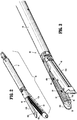
FIG. 2 is a front, perspective view of a surgical loading unit of the surgical instrument ofFIG. 1 ; -
FIG. 3 is an enlarged perspective view of the surgical loading unit ofFIG. 2 illustrating an inflatable member of the surgical loading unit in an inflated state; -
FIG. 4 is a side view of the surgical loading unit ofFIG. 3 positioned at a surgical site via an access port; -
FIG. 5 is a partial, side view of the surgical loading unit ofFIG. 3 illustrating tissue disposed between jaw members of the surgical loading unit with the inflatable member in a collapsed state and the jaw members in a partially open position; -
FIG. 6 is a partial, side view of the surgical loading unit ofFIG. 3 illustrating tissue disposed between the jaw members with the inflatable member in an expanded state and the jaw members in the partially open position; -
FIG. 7 is a partial, side view of the surgical loading unit ofFIG. 3 illustrating the jaw members clamped about the tissue with the inflatable member in the expanded state; -
FIG. 8 is a perspective view of another embodiment of a surgical system including a display and a surgical instrument including the surgical loading unit ofFIG. 3 ; -
FIG. 9 is yet another embodiment of a surgical system including a display and a surgical instrument; -
FIG. 10 is a perspective view, with parts separated, of a surgical loading unit and an adapter assembly of the surgical instrument ofFIG. 9 ; -
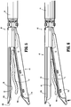
FIG. 11 is an enlarged, perspective view of the surgical loading unit ofFIG. 10 ; -
FIG. 12 is yet another embodiment of a surgical system including a display and a surgical instrument; and -
FIG. 13 is a perspective view, with parts separated, of a handle portion and an adapter assembly/jaw assembly of the surgical instrument ofFIG. 12 . - Embodiments of the presently disclosed surgical instruments and systems will now be described in detail with reference to the drawing figures wherein like reference numerals identify similar or identical elements. As used herein and as is traditional, the term "distal" will refer to that portion which is further from the user while the term "proximal" will refer to that portion which is closer to the user.
-
FIG. 1 illustrates asurgical system 1 which generally includes a surgical instrument such as a surgical stapler 10 in communication with adisplay 20 for displaying measurements taken by the surgical stapler 10. The surgical stapler 10 is configured to staple grasped tissue and to sense biological parameters of the tissue to assist a clinician in determining whether to effect a stapling function of the surgical stapler 10, as will be described in detail herein. For example, the surgical stapler 10 is configured to determine a surface perfusion pressure of a subject tissue. In embodiments, the surgical stapler 10 is configured for use in laparoscopic surgical procedures. The surgical stapler can be arranged for use in a robotic surgical system. - The surface perfusion pressure of tissue is measured by applying clamping pressure on the tissue until there is no perfusion (i.e., no blood flow) through the tissue, and then slowly reducing the clamping pressure until perfusion through the grasped tissue restarts. The pressure at which the perfusion restarts is known as "surface perfusion pressure."
- For a detailed description of a method of measuring surface perfusion pressure, reference may be made to
U.S. Patent No. 7,618,376 . - The surgical stapler 10 generally includes a handle portion 12, an
adapter assembly 14, anelongated shaft 30, and asurgical loading unit 40. The handle portion 12 of the surgical stapler 10 includes astationary handle 16 and a pivoting ormovable handle 18 pivotably coupled to thestationary handle 16. Manipulation of thepivoting handle 18 relative to thestationary handle 16 effects a closing ofjaw members surgical loading unit 40 to grasp tissue disposed between thejaw members U.S. Patent No. 7,172,104 . - The
surgical loading unit 40 has anelongate body portion 44 and anend effector 46 coupled to thebody portion 44. Thebody portion 44 is detachably coupled to a distal portion of theelongated shaft 30 or, in some embodiments, may be fixedly coupled to the distal portion of theelongated shaft 30. Theend effector 46 of thesurgical loading unit 40 is pivotably coupled to a distal portion of thebody portion 44 such that theend effector 46 may be articulated about an axis transverse to a longitudinal axis of thebody portion 44 between a linear orientation and an angled orientation relative to the longitudinal axis. In some embodiments, theend effector 46 may be fixedly attached to the distal portion of theelongated shaft 30. - With reference to
FIGS. 1-3 , theend effector 46 includes a pair ofopposing jaw members jaw member 42a is configured as a staple cartridge and thejaw member 42b is configured as an anvil. Thestaple cartridge 42a and theanvil 42b each define a respective tissue-contactingsurface surfaces end effector 46 is in the closed configuration, tissue is grasped between thetissue contacting surfaces surface 48a of thestaple cartridge 42a defines a plurality of staple-receivingchannels 50, and the tissue-contactingsurface 48b of theanvil 42b defines a plurality of staple forming pockets 52. As such, thestaple cartridge 42a and theanvil 42b are configured to clamp and then staple tissue disposed therebetween in response to an actuation of the movable handle of the handle portion 12. - The
end effector 46 of thesurgical loading unit 40 includes an inflatable member 56 (FIG. 3 ), such as, for example, a balloon, disposed on the tissue-contactingsurface 48b of theanvil 42b. In other embodiments, theinflatable member 46 may be disposed on the tissue-contactingsurface 48a of thestaple cartridge 42a. In still other embodiments, each of thestaple cartridge 42a and theanvil 42b may have an inflatable member disposed on its respective tissue-contactingsurface inflatable member 56 may be attached to the tissue-contactingsurface 48b via an adhesive, a hook and loop fastener, a suture, or the like. In some embodiments, theinflatable member 56 may be detachably connected to the tissue-contactingsurface 48b. In other embodiments, theinflatable member 56 may be detachably connected to the tissue-contactingsurface 48b such that upon an actuation of the stapling function of theend effector 46, the staples ejected from thestaple cartridge 42a release theinflatable member 56 from the tissue-contactingsurface 48b, for example, by severing a suture that attaches theinflatable member 56 to the tissue-contactingsurface 48b. - The
inflatable member 56 has a generally rectangular shape dimensioned to cover the tissue-contactingsurface 48b of theanvil 42b such that thestaple forming pockets 52 defined in tissue-contactingsurface 48b are covered by theinflatable member 56. Theinflatable member 56 is fabricated from a biocompatible material such as natural or synthetic elastomers, natural or synthetic rubbers and silicone materials, and/or compliant polyurethanes. Theinflatable member 56 may be made of a material that is penetrable by the staples ejected from thestaple cartridge 42a so as to not inhibit the stapling function of theend effector 46. - The
inflatable member 56 defines a hollow inner chamber or void 60 that receives a fluid to change or move theinflatable member 56 from a collapsed configuration, in which theinflatable member 56 is substantially flat and rectangular (FIG. 5 ), to an expanded configuration, in which theinflatable member 56 is larger than in the collapsed configuration and assumes a bulbous configuration (FIG. 6 ). In some embodiments, theinflatable member 56 may be configured to assume any suitable shape when in the expanded configuration, such as, for example, rectangular, dome-shaped, elliptical, oblong, tubular, square, triangular, cylindrical, rod-shaped, or the like. - The
inflatable member 56 may have a hose or tube 58 (FIG. 1 ) extending therefrom and in fluid communication with the hollow inner chamber 60 (FIG. 3 ). Thetube 58 may extend from theinflatable member 56, proximally through thebody portion 44 of thesurgical loading unit 40, theelongated shaft 30, and out of theadapter assembly 14. Thetube 58 may have an end 62 (FIG. 1 ) coupled to a source of fluid, such as, for example, a pump (not explicitly shown), for delivering a fluid, such as liquid and/or gas, into the hollow inner chamber 60 (FIG. 3 ) of theinflatable member 56. Theend 62 oftube 58 may be in communication with the display 20 (FIG. 1 ) or a processor of thedisplay 20. - The
end effector 46 of thesurgical loading unit 40 includes a first sensor 64 (FIG. 3 ) and a second sensor 66 (FIG. 3 ) each associated with theanvil 42b. In particular, the first andsecond sensors inflatable member 56 of theanvil 42b and in communication with thedisplay 20. In some embodiments, thefirst sensor 64 may be attached to one or both of the tissue-contactingsurfaces respective staple cartridge 42a andanvil 42b. Thefirst sensor 64 is a perfusion sensor, for example, a Doppler flow sensor, configured to measure local perfusion (i.e., blood flow) through tissue grasped between thestaple cartridge 42a and theanvil 42b. Thefirst sensor 64 may measure perfusion of the grasped tissue on the basis of known techniques, such as Laser-Doppler Flowmetry ("LDF"), measuring light scattering, and/or measuring absorption of light from one or more LED's or other light sources. For a detailed description of LDF technology, reference may be made toU.S. Patent Nos. 4,109,647 and4,862,894 . - The
first sensor 64 is in communication, via lead wires or wireless connection, with thedisplay 20 such that upon thefirst sensor 64 measuring perfusion in grasped tissue, thefirst sensor 64 transmits the measurement data to afirst display section 20a of thedisplay 20, which displays the measurement using a number, word, or image. - In some embodiments, the
first sensor 64 may also be in communication, via lead wires or wireless connection, with a computing device or processor (not shown) such as a laser Doppler monitor, which processes the information collected by thefirst sensor 64 to calculate the tissue perfusion. The computing device (e.g., a laser Doppler monitor) may also be in communication, via lead wires or wireless connection, with thefirst display section 20a to send the processed information related to the tissue perfusion to thefirst display section 20a so that thefirst display section 20a can display the tissue perfusion. - The
second sensor 66 of theend effector 46 is a pressure sensor or pressure measuring device, for example, a MEMS device. For a detailed description of various MEMS devices, reference may be made toU.S. Patent No. 8,808,311 . In embodiments, thesecond sensor 66 is disposed within the hollowinner chamber 60 of theinflatable member 56 and is configured to measure the amount of pressure applied by theend effector 46 to the grasped tissue (i.e., the clamping pressure) by measuring the pressure within theinflatable member 56. In addition to or in the alternative (not forming part of the present invention) ofinflatable member 56 having a pressure sensor,tissue contacting surface 48a of thestaple cartridge 42a may also have a pressure sensor for measuring the amount of pressure applied by theend effector 46 to the grasped tissue. - The second sensor 66 (
FIG. 3 ) is in electrical communication, via lead wires or wireless connection, with asecond display section 20b (FIG. 1 ) of thedisplay 20. After thesecond sensor 66 measures the clamping pressure applied to the grasped tissue, thesecond sensor 66 transmits the measurement data to thesecond display section 20b, which displays the measurement, Additionally or alternately, thesecond sensor 66 may send the measured clamping pressure to the computing device (e.g., a laser Doppler monitor) for processing, which then sends the information to thedisplay 20. - The
display 20 may have multiple display sections, for example, threedisplay sections display 20 may include more or less than three discrete display sections arranged in any suitable configuration. In embodiments, thefirst display section 20a of thedisplay 20 is configured to display a visual indication of a measured tissue perfusion of tissue grasped by theend effector 46. Thesecond display section 20b of thedisplay 20 is configured to display a visual indication of a measured amount of pressure being applied to tissue grasped by theend effector 46. Athird display section 20c of thedisplay 20 is configured to display an index representative of the ratio of the surface perfusion pressure determined using the first andsecond sensors - In some embodiments, the display 20 (
FIG. 1 ) may display ranges of numbers or various numeral outputs to display the measurements of first andsecond sensors third display sections end effector 46. For example, when thefirst display section 20a displays the number 0, this may be an indication that the grasped tissue has very little or no perfusion (i.e., no blood flow), whereas when thefirst display section 20a displays thenumber 100, this may be an indication that the grasped tissue has a high perfusion (i.e., ideal blood flow). - In some embodiments, the
display 20 may convey information about a characteristic of the grasped tissue utilizing any suitable indicia, for example, words such as poor, satisfactory, or good. - In some embodiments, the
surgical system 1 may not include thedisplay 20, and instead, surgical stapler 10 may be configured to be connected to or be in communication with another type of display, for example, a tablet, a cell phone, a computer monitor, a laptop, or any suitable display device. The surgical stapler 10 may be connected to any of the aforementioned display devices via USB wires, Wi-Fi, or the like. - In operation, the
surgical system 1 may be used in a surgical procedure in which tissue is to be stapled, for example, an anastomotic surgical procedure, to gather various data about the subject tissue prior to effecting stapling. In some anastomotic surgical procedures, unhealthy or diseased bowel tissue is resected and the ends of the remaining healthy segments of bowel are stapled together to recreate a continuous bowel. Prior to stapling the ends of the separate bowel segments to one another, the viability of the ends of the separate bowel segments should be assessed in order to predict the likelihood of post-surgery anastomotic leaks or other adverse outcomes. To aid in making this viability assessment, a clinician may make use of thesurgical system 1 of the present disclosure. - With reference to
FIG. 4 , in use of thesurgical system 1, thesurgical loading unit 40 is positioned through anaccess port 70 to gain entry to a surgical site in a minimally invasive manner. With theinflatable member 56 of theend effector 46 in a collapsed or un-inflated state, tissue "T" is disposed between thetissue contacting surface 48a of thestaple cartridge 42a and theinflatable member 56 disposed on the tissue-contactingsurface 48b of theanvil 42b with thestaple cartridge 42a and theanvil 42b in a partially open position, as shown inFIG. 5 . With the tissue "T" disposed between thestaple cartridge 42a and theanvil 42b, the pump of thesurgical system 1 conveys a fluid (e.g., air) into the hollowinner chamber 60 of theinflatable member 56 via thetube 58 to change theinflatable member 56 from its collapsed state toward its expanded or inflated state, as shown inFIG. 6 . With theinflatable member 56 in the expanded state, thestaple cartridge 42a and theanvil 42b are clamped about the tissue "T," as shown inFIG. 7 . - In one embodiment, the
staple cartridge 42a and theanvil 42b may be clamped about the tissue "T" prior to expanding theinflatable member 56. As the pressure inside of theinflatable member 56 increases, the pressure applied to the tissue "T" disposed betweenstaple cartridge 42a and theanvil 42b increases to inhibit blood flow through the tissue. - With the
inflatable member 56 in the inflated state and the tissue "T" being grasped by theend effector 46, thefirst sensor 64 of theend effector 46 collects information about the perfusion through the grasped tissue. This information is transmitted to thefirst display section 20a of thedisplay 20, which displays this information as an image of the blood flow or as a number representative of the degree of perfusion through the tissue "T." Thesecond sensor 66 measures the pressure within theinflatable member 56 and sends this information to thesecond display section 20b of thedisplay 20, which displays this information as a number. While a clinician monitors the perfusion reading (i.e., blood flow) displayed on thefirst display section 20a and the pressure reading displayed on thesecond display section 20b, expansion of theinflatable member 56 is gradually continued to gradually increase the clamping pressure between thestaple cartridge 42a and theanvil 42b, until the perfusion reading indicates that no blood flow or virtually no blood flow is moving through the grasped tissue "T." - In embodiments, instead of gradually increasing the clamping pressure on the tissue "T" by inflating the
inflatable member 56, the pivotinghandle 16 is actuated to gradually close thestaple cartridge 42a and theanvil 42b about the tissue "T." A clinician will cease approximating thestaple cartridge 42a and theanvil 42b when thedisplay section 20a indicates that no blood or virtually no blood is flowing through the tissue "T." - When the
first display section 20a indicates that perfusion through the grasped tissue has ceased, a clinician continuously monitors both the first andsecond display sections inflatable member 56, decreasing the pressure applied to the grasped tissue "T." In embodiments, the pressured applied to the tissue "T" may be decreased by separating thestaple cartridge 42a and theanvil 42b rather than by deflating theinflatable member 56. The clamping pressure is reduced until thefirst display section 20a displays a perfusion reading indicating that blood flow has returned to the grasped tissue. At the moment that the perfusion reading indicates that the blood flow is returned, the pressure reading (e.g., the pressure in inflatable member 56) displayed by thesecond display section 20b is noted, which is marks the local perfusion pressure of the grasped tissue. - The local perfusion pressure determined using the above-noted technique may be used to assess the viability of the grasped tissue by, for example, comparing the measured local perfusion pressure with a known local perfusion pressure associated with healthy or viable tissue. Additionally or alternately, the measured local perfusion pressure may be used in combination with other measurements, for example, a systemic blood pressure reading, to aid in making the determination of the viability of the tissue. The systemic blood pressure may be taken using any suitable device, for example, a blood pressure cuff, applied to any suitable body portion of the patient, for example, an arm of the patient. An index may be calculated by taking a ratio of the local perfusion pressure measured by the surgical stapler 10 and the systemic blood pressure taken using the blood pressure cuff. The index may be calculated by the computing device in the
display 20 and displayed as a number on thethird display section 20c of thedisplay 20. - The calculated index is predictive of whether an anastomotic leak may occur and/or the grade of an anastomotic leak. As such, a clinician can use the index to make a determination on whether the two ends of the presumed healthy bowel segments are healthy enough to be stapled together or whether more tissue needs to be resected. For example, the calculated index may be compared to a known index that is associated with healthy tissue. For a detailed description of a method of calculating a perfusion index and using the calculated index to assess tissue viability, reference may be made to
U.S. Patent No. 7,618,376 . - After determining that the grasped tissue "T" is viable, the
movable handle 18 of the surgical stapler 10 may be actuated to eject staples from the staple-receivingchannels 50 of thestaple cartridge 42a into the tissue "T." The staples contact the staple-formingpockets 52 of theanvil 42b to close the staples about the tissue "T." As the staples are ejected, a cutting blade (not shown) moves through theend effector 46 to cut the stapled tissue "T," thereby dividing the tissue "T" into two tissue segments. - In this way, a clinician only needs to use one instrument, namely the surgical stapler 10 of the present disclosure, to both determine tissue viability and to effect a stapling procedure once it is determined that the tissue is viable. One benefit to having only one instrument to accomplish each of these tasks is that once the surgical instrument determines that a particular segment of tissue is viable, the clinician can immediately staple the tissue without having to use a separate surgical stapler.
- In some embodiments, the surgical stapler 10 may be pre-programmed to inflate the
inflatable member 56 to exert a predetermined clamping pressure that is known to result in a ceasing of perfusion through the grasped tissue. The surgical stapler 10 may also be pre-programmed to reduce the clamping pressure at a predetermined rate via deflation of theinflatable member 56 and automatically send the pressure reading to the computing device at the moment when perfusion through the grasped tissue restarts. The perfusion pressure reading may also be displayed on thedisplay 20. This automated process eliminates human error in operating the surgical stapler 10 by controlling the amount of clamping pressure being applied to the tissue at any given time instead of the clinician. - In addition to the
surgical system 1 being used to ensure that the tissue is in condition for stapling or acceptable for stapling, thesurgical system 1 may also be used as a check after the staples have been fired to ensure that the tissue is healthy (e.g., has good blood flow, is healing properly, etc.). - The
surgical system 1 or components thereof may be configured to be incorporated into a robotic surgical system (not shown). The robotic surgical system is powered locally or remotely, and has electronic control systems localized in a console or distributed within or throughout the robotic surgical system. The robotic surgical system permits a clinician to remotely manipulate the surgical stapler 10 to more precisely control the movement of the surgical stapler 10. The surgical stapler 10 may be configured to send the measurements gathered by thesensors end effector 46 to an interface of the robotic surgical system on which the measurements may be displayed for the clinician to read. In any of the embodiments disclosed herein, the surgical instrument can be a surgical stapler other than a linear endoscopic surgical stapler. For example, a circular stapler can incorporate a perfusion system disclosed herein. - As illustrated in
FIG 8 , another embodiment of asurgical instrument 100 for use with thedisplay 20 is provided. Thesurgical instrument 100 is similar to surgical stapler 10 described with reference toFIGS. 1-7 , and will therefore only be described with the detail necessary to elucidate differences. -
Surgical instrument 100 is a surgical stapler configured to both staple tissue and to determine tissue viability using an inflatable member (not explicitly shown), a perfusion sensor (not explicitly shown), and a pressure sensor (not explicitly shown), As described above in regard to the surgical stapler 10, thesurgical instrument 100 includes ahandle portion 112, anadapter assembly 114, anelongated shaft 130, and asurgical loading unit 140. However, rather than being manually-powered as is the surgical stapler 10 ofFIGS. 1-7 , thesurgical instrument 100 of the present embodiment actuates functions of the surgical loading unit 140 (e.g., stapling, cutting, closing/opening of the jaws, etc.) via an internal-power source disposed within thehandle portion 112. For a detailed description of an exemplary internally-powered handle portion of a surgical stapler, reference may be made toU.S. Patent Application Publication No. 2016/0118201, filed on July 24, 2015 . - As illustrated in
FIGS. 9-11 , an example not forming part of the present invention of asurgical instrument 200 for use with thedisplay 20 is provided. Thesurgical instrument 200 is similar to the surgical stapler 10 described with reference toFIGS. 1-7 , and will therefore only be described with the detail necessary to elucidate differences. -
Surgical instrument 200 is a non-stapling tissue grasper configured to determine tissue viability of grasped tissue. Thetissue grasper 200 includes ahandle portion 212, anadapter assembly 214, and asurgical loading unit 240. Theadapter assembly 214 includes a housing orknob 214a and anelongated shaft 214b extending distally therefrom. Theknob 214a of theadapter assembly 214 is configured to detachably couple to thehandle portion 212. - The
surgical loading unit 240 has an elongatedbody portion 244 and ajaw assembly 246 coupled to thebody portion 244. Thebody portion 244 is detachably coupled to a distal portion of theelongated shaft 214b of theadapter assembly 214. Thejaw assembly 246 includes afirst jaw 242a and asecond jaw 242b each coupled to the distal portion of thebody portion 244. Thefirst jaw 242a is pivotably coupled to thebody portion 244 such that thefirst jaw member 242a is movable relative to thesecond jaw member 242b between a spaced condition and an approximated condition. In some examples, one or both of thejaw members body portion 244 of thesurgical loading unit 240. - The
first jaw member 242a has a tissue-contactingsurface 248a and thesecond jaw member 242b has aninner surface 248b that defines an elongated cavity 250 (FIG. 11 ) therein. Thejaw assembly 246 includes aninflatable member 256, similar toinflatable member 56 described above, received within thecavity 250 of thesecond jaw member 242b. Theinflatable member 256 may be dimensioned for a snap-fit engagement with theinner surface 248b of thesecond jaw member 242b. Theinflatable member 256 has a generally rectangular shape dimensioned to contact the tissue-contactingsurface 248a of thefirst jaw member 242a when thejaw assembly 244 is in the approximated state. - The
inflatable member 256 is configured to be changed or moved from a collapsed configuration, in which theinflatable member 256 is substantially flat and rectangular, to an expanded configuration, in which theinflatable member 256 is larger than in the collapsed configuration and assumes a bulbous configuration. Theinflatable member 256 may have a hose or tube 258 (FIG. 9 ) extending therefrom and in fluid communication with a hollowinner chamber 260 defined in theinflatable member 256. Thetube 258 may have anend 262 coupled to a source of fluid, such as, for example, a pump (not explicitly shown), for delivering a fluid such as liquid and/or gas into hollowinner chamber 260 of theinflatable member 256. - The
jaw assembly 140 includes a perfusion sensor 264 (FIG. 11 ), similar to thefirst sensor 64 described above, and apressure sensor 266, similar to thesecond sensor 66 described above. Theperfusion sensor 264 is attached to the inflatable member 256 (e.g., an inner or outer surface thereof) of thesecond jaw member 242b and in communication with thedisplay 20. In some examples, theperfusion sensor 264 may be attached to the tissue-contactingsurface 248a of thefirst jaw ember 242a or theinner surface 248b of thesecond jaw member 242b rather than theinflatable member 256. - In examples, the pressure sensor 266 (
FIG. 11 ) of thejaw assembly 246 is disposed within the hollowinner chamber 260 of theinflatable member 256 and is configured to measure the amount of pressure applied by thejaw assembly 246 to the grasped tissue (i.e., the clamping pressure) by measuring the pressure within theinflatable member 256. In addition to or in the alternative ofinflatable member 256 having a pressure sensor, thetissue contacting surface 248a of thefirst jaw member 242a may also have a pressure sensor for measuring the amount of pressure applied by thejaw assembly 246 to the grasped tissue. - The
tissue grasper 200 is used in a similar manner as described above with respect to the surgical stapler 10 except that thetissue grasper 200 does not effect a stapling of the grasped tissue after the viability of the grasped tissue is assessed. - As illustrated in
FIGS. 12 and13 , another example not forming part of the present invention of asurgical instrument 300 for use with thedisplay 20 is provided. Thesurgical instrument 300 is similar to thesurgical instrument 200 described above with reference toFIGS. 9-11 , and will therefore only be described with the detail necessary to elucidate differences. - The
surgical instrument 300 is a tissue grasper configured to grasp tissue and determine viability of the grasped tissue using aninflatable member 256, a perfusion sensor (not explicitly shown), and a pressure sensor (not explicitly shown). Thetissue grasper 300 includes ahandle portion 312, anadapter assembly 314, and ajaw assembly 340. Rather than thetissue grasper 300 having a detachable loading unit, thejaw assembly 340 is fixed to theelongated shaft 314b of theadapter assembly 314, and a housing orknob 314a of theadapter assembly 314 is detachably coupled to thehandle portion 312. - Although the illustrative embodiments and examples of the present disclosure have been described herein, it is understood that the disclosure is not limited to those precise embodiments and examples, and that various other changes and modifications may be affected therein by one skilled in the art without departing from the scope of the disclosure. All such changes and modifications are intended to be included within the scope of the disclosure.
Claims (11)
- A surgical instrument (10), comprising:a pair of jaw members (42a, 42b) movable relative to one another between spaced and approximated positions, wherein the pair of jaw members is configured to staple tissue disposed therebetween;an inflatable member (56) associated with at least one of the pair of jaw members, the inflatable member configured to apply pressure to tissue disposed between the pair of jaw members;a first sensor (64) associated with at least one of the pair of jaw members, the first sensor configured to measure local perfusion in the tissue disposed between the pair of jaw members, anda second sensor (66) in communication with the inflatable member and configured to measure a pressure within the inflatable member;whereby the local perfusion pressure of the tissue corresponds to the pressure reading of the second sensor at the moment the perfusion reading of the first sensor indicates blood flow has returned;and wherein the surgical instrument comprises: a handle portion (12) and a shaft (30) coupled to the handle portion (12), wherein the pair of jaw members are operably coupled to the shaft and are movable relative to one another between spaced and approximated positions in response to an actuation of the handle portionor wherein the surgical instrument is a surgical loading unit (40) comprising an elongate body (44) having a proximal portion and a distal portion and an end effector (46) coupled to the distal portion of the elongate body, the end effector including said pair of jaw members, said inflatable member, and said first and second sensors.
- The surgical instrument according to claim 1, wherein at least one of the jaw members includes a tissue-contacting surface (48a, 48b), the inflatable member being at least partially disposed on the tissue-contacting surface such that the inflatable member is clamped between the pair of jaw members when the pair of jaw members is in the approximated position.
- The surgical instrument according to claim 1 or 2, wherein the inflatable member is disposed within a cavity (250) defined in the at least one jaw member.
- The surgical instrument according to any preceding claim, wherein a first jaw member of the pair of jaw members includes a tissue-contacting surface that defines staple-forming pockets (52) and a second jaw member of the pair of jaw members includes a tissue-contacting surface that defines staple-receiving channels (50).
- The surgical instrument according to any preceding claim, wherein the inflatable member is a balloon fabricated from an elastomer.
- The surgical instrument according to any preceding claim, wherein the inflatable member has a tube (58) configured to be in fluid communication with a pump for inflating the inflatable member.
- The surgical instrument according to any preceding claim, wherein the inflatable member is configured to transition between a collapsed state, in which the inflatable member is substantially flat, and an expanded state, in which the inflatable member is bulbous.
- The surgical instrument according to any preceding claim, wherein the inflatable member defines a hollow inner chamber (60) therein.
- The surgical instrument according to the first alternative of claim 1, wherein said handle portion includes a manual trigger for effecting a closing of the pair of jaw members.
- The surgical instrument according to claim 9, wherein the handle portion is configured to effect a closing of the pair of jaw members via an internal power source.
- The surgical instrument according to claim 9 or 10, further comprising an adapter assembly (14) interposed between the handle portion and the shaft.
Applications Claiming Priority (1)
| Application Number | Priority Date | Filing Date | Title |
|---|---|---|---|
| US15/453,241 US10687811B2 (en) | 2017-03-08 | 2017-03-08 | Surgical instruments including sensors |
Publications (2)
| Publication Number | Publication Date |
|---|---|
| EP3372172A1 EP3372172A1 (en) | 2018-09-12 |
| EP3372172B1 true EP3372172B1 (en) | 2021-06-30 |
Family
ID=61581089
Family Applications (1)
| Application Number | Title | Priority Date | Filing Date |
|---|---|---|---|
| EP18160402.6A Active EP3372172B1 (en) | 2017-03-08 | 2018-03-07 | Surgical instruments including sensors |
Country Status (6)
| Country | Link |
|---|---|
| US (2) | US10687811B2 (en) |
| EP (1) | EP3372172B1 (en) |
| JP (1) | JP7123575B2 (en) |
| AU (1) | AU2018200847A1 (en) |
| CA (1) | CA2993570A1 (en) |
| ES (1) | ES2882400T3 (en) |
Families Citing this family (6)
| Publication number | Priority date | Publication date | Assignee | Title |
|---|---|---|---|---|
| US10687811B2 (en) | 2017-03-08 | 2020-06-23 | Covidien Lp | Surgical instruments including sensors |
| NL2020240B1 (en) * | 2018-01-05 | 2019-07-12 | Veenhof Medical Devices B V | Testing tissue viability for an anastomosis |
| US20230056943A1 (en) * | 2019-12-13 | 2023-02-23 | Dinesh Vyas | Stapler apparatus and methods for use |
| US20210177402A1 (en) | 2019-12-13 | 2021-06-17 | Dinesh Vyas | Stapler apparatus and methods for use |
| US11266402B2 (en) * | 2020-07-30 | 2022-03-08 | Covidien Lp | Sensing curved tip for surgical stapling instruments |
| US11864724B2 (en) | 2021-07-22 | 2024-01-09 | Vitalitec International, Inc. | Occlusion device |
Citations (1)
| Publication number | Priority date | Publication date | Assignee | Title |
|---|---|---|---|---|
| US20140288386A1 (en) * | 2013-03-19 | 2014-09-25 | Surgisense Corporation | Apparatus, systems and methods for determining tissue oxygenation |
Family Cites Families (43)
| Publication number | Priority date | Publication date | Assignee | Title |
|---|---|---|---|---|
| US4109647A (en) | 1977-03-16 | 1978-08-29 | The United States Of America As Represented By The Secretary Of The Department Of Health, Education And Welfare | Method of and apparatus for measurement of blood flow using coherent light |
| AU608807B2 (en) | 1987-03-03 | 1991-04-18 | Hitoshi Fujii | Apparatus for monitoring bloodstream |
| US5383880A (en) | 1992-01-17 | 1995-01-24 | Ethicon, Inc. | Endoscopic surgical system with sensing means |
| US5772597A (en) | 1992-09-14 | 1998-06-30 | Sextant Medical Corporation | Surgical tool end effector |
| CA2124109A1 (en) | 1993-05-24 | 1994-11-25 | Mark T. Byrne | Endoscopic surgical instrument with electromagnetic sensor |
| US5722419A (en) | 1994-11-30 | 1998-03-03 | Semmlow; John L. | System for determining the viability of tissue |
| US20040127800A1 (en) | 1995-07-06 | 2004-07-01 | Kimball Victor E. | Device for assessing perfusion failure in a patient by measurement of blood flow |
| US20030120306A1 (en) | 2000-04-21 | 2003-06-26 | Vascular Control System | Method and apparatus for the detection and occlusion of blood vessels |
| US7223279B2 (en) | 2000-04-21 | 2007-05-29 | Vascular Control Systems, Inc. | Methods for minimally-invasive, non-permanent occlusion of a uterine artery |
| US6606510B2 (en) * | 2000-08-31 | 2003-08-12 | Mallinckrodt Inc. | Oximeter sensor with digital memory encoding patient data |
| EP1377223A2 (en) | 2001-03-28 | 2004-01-07 | Vascular Control Systems, Inc. | Method and apparatus for the detection and ligation of uterine arteries |
| ES2377483T3 (en) | 2002-04-25 | 2012-03-28 | Tyco Healthcare Group Lp | Surgical instruments that include microelectromechanical systems (MEMS) |
| US8996090B2 (en) | 2002-06-03 | 2015-03-31 | Exostat Medical, Inc. | Noninvasive detection of a physiologic parameter within a body tissue of a patient |
| WO2004069030A2 (en) | 2003-01-31 | 2004-08-19 | Verimetra, Inc. | Medical and surgical devices with an integrated sensor |
| US7651511B2 (en) | 2003-02-05 | 2010-01-26 | Vascular Control Systems, Inc. | Vascular clamp for caesarian section |
| US7172104B2 (en) | 2004-02-17 | 2007-02-06 | Tyco Healthcare Group Lp | Surgical stapling apparatus |
| EP2441396B1 (en) * | 2004-10-18 | 2015-01-21 | Covidien LP | Annular adhesive structure |
| US20060106288A1 (en) * | 2004-11-17 | 2006-05-18 | Roth Alex T | Remote tissue retraction device |
| WO2006113394A2 (en) | 2005-04-15 | 2006-10-26 | Surgisense Corporation | Surgical instruments with sensors for detecting tissue properties, and systems using such instruments |
| US7717312B2 (en) | 2005-06-03 | 2010-05-18 | Tyco Healthcare Group Lp | Surgical instruments employing sensors |
| WO2007008057A1 (en) | 2005-07-14 | 2007-01-18 | Erasmus University Medical Center Rotterdam | Tissue vitality monitoring system and method and surgical technique |
| US9237891B2 (en) * | 2005-08-31 | 2016-01-19 | Ethicon Endo-Surgery, Inc. | Robotically-controlled surgical stapling devices that produce formed staples having different lengths |
| US8073518B2 (en) | 2006-05-02 | 2011-12-06 | Nellcor Puritan Bennett Llc | Clip-style medical sensor and technique for using the same |
| NL2000427C2 (en) | 2007-01-10 | 2008-07-11 | Univ Delft Tech | Laparoscopic gripping instrument. |
| US8157145B2 (en) | 2007-05-31 | 2012-04-17 | Ethicon Endo-Surgery, Inc. | Pneumatically powered surgical cutting and fastening instrument with electrical feedback |
| US8118206B2 (en) | 2008-03-15 | 2012-02-21 | Surgisense Corporation | Sensing adjunct for surgical staplers |
| US9504781B2 (en) | 2008-12-19 | 2016-11-29 | Cvdevices, Llc | Peripheral arterialization devices and methods of using the same |
| US8958860B2 (en) * | 2010-05-17 | 2015-02-17 | Covidien Lp | Optical sensors for intraoperative procedures |
| US9655555B2 (en) * | 2011-03-07 | 2017-05-23 | Potrero Medical, Inc. | Sensing foley catheter |
| NL2007038C2 (en) | 2011-07-04 | 2013-01-07 | Vereniging Voor Christelijk Hoger Onderwijs | System and method for predicting the viability of a body tissue in a patient, and measuring device used therein. |
| JP5684767B2 (en) | 2011-09-26 | 2015-03-18 | アークレイ株式会社 | Lactic acid sensor |
| US20140107697A1 (en) | 2012-06-25 | 2014-04-17 | Castle Surgical, Inc. | Clamping Forceps and Associated Methods |
| TW201409026A (en) | 2012-08-28 | 2014-03-01 | Univ Nat Yunlin Sci & Tech | Potentiometric lactate senor, method for forming thereof and measuring system including thereof |
| US9572529B2 (en) * | 2012-10-31 | 2017-02-21 | Covidien Lp | Surgical devices and methods utilizing optical coherence tomography (OCT) to monitor and control tissue sealing |
| US9522002B2 (en) | 2012-12-13 | 2016-12-20 | Covidien Lp | Surgical instrument with pressure distribution device |
| WO2015057533A1 (en) * | 2013-10-14 | 2015-04-23 | Adagio Medical, Inc. | Endoesophageal balloon catheter, system, and related method |
| US20150173789A1 (en) * | 2013-12-23 | 2015-06-25 | Ethicon Endo-Surgery, Inc. | Surgical instruments with articulatable shaft arrangements |
| US9991069B2 (en) | 2014-10-22 | 2018-06-05 | Covidien Lp | Surgical instruments and switch assemblies thereof |
| CN107613858A (en) * | 2015-04-09 | 2018-01-19 | 通用医疗公司 | System and method for non-invasive monitoring intracranial pressure |
| US11020578B2 (en) * | 2015-04-10 | 2021-06-01 | Covidien Lp | Surgical stapler with integrated bladder |
| JP6214831B1 (en) * | 2016-04-26 | 2017-10-18 | オリンパス株式会社 | Treatment system and control device |
| US10499912B2 (en) * | 2016-07-13 | 2019-12-10 | Ethicon Llc | Apparatus for hydraulic assisted fracture of liver parenchyma |
| US10687811B2 (en) | 2017-03-08 | 2020-06-23 | Covidien Lp | Surgical instruments including sensors |
-
2017
- 2017-03-08 US US15/453,241 patent/US10687811B2/en active Active
-
2018
- 2018-01-31 CA CA2993570A patent/CA2993570A1/en active Pending
- 2018-02-06 AU AU2018200847A patent/AU2018200847A1/en not_active Abandoned
- 2018-03-07 ES ES18160402T patent/ES2882400T3/en active Active
- 2018-03-07 EP EP18160402.6A patent/EP3372172B1/en active Active
- 2018-03-07 JP JP2018040897A patent/JP7123575B2/en active Active
-
2020
- 2020-06-02 US US16/890,135 patent/US11253257B2/en active Active
Patent Citations (1)
| Publication number | Priority date | Publication date | Assignee | Title |
|---|---|---|---|---|
| US20140288386A1 (en) * | 2013-03-19 | 2014-09-25 | Surgisense Corporation | Apparatus, systems and methods for determining tissue oxygenation |
Also Published As
| Publication number | Publication date |
|---|---|
| US20200289118A1 (en) | 2020-09-17 |
| ES2882400T3 (en) | 2021-12-01 |
| JP2018143773A (en) | 2018-09-20 |
| US11253257B2 (en) | 2022-02-22 |
| AU2018200847A1 (en) | 2018-09-27 |
| CA2993570A1 (en) | 2018-09-08 |
| JP7123575B2 (en) | 2022-08-23 |
| EP3372172A1 (en) | 2018-09-12 |
| US10687811B2 (en) | 2020-06-23 |
| US20180256163A1 (en) | 2018-09-13 |
Similar Documents
| Publication | Publication Date | Title |
|---|---|---|
| EP3372172B1 (en) | Surgical instruments including sensors | |
| AU2012238268B2 (en) | System and method of using simulation reload to optimize staple formation | |
| US10624616B2 (en) | Surgical instruments including sensors | |
| EP2491872A1 (en) | Controlled tissue compression systems and methods | |
| CN108852442B (en) | Surgical instrument for measuring blood pressure | |
| EP3420971A1 (en) | Surgical instruments including sensors | |
| US20180256161A1 (en) | Surgical instruments including sensors | |
| US20230338108A1 (en) | Powered surgical instruments and methods of identifying tissue types therewith | |
| US11849942B2 (en) | Sensing curved tip for surgical stapling instruments | |
| AU2015201050A1 (en) | System and method of using simulation reload to optimize staple formation |
Legal Events
| Date | Code | Title | Description |
|---|---|---|---|
| PUAI | Public reference made under article 153(3) epc to a published international application that has entered the european phase |
Free format text: ORIGINAL CODE: 0009012 |
|
| STAA | Information on the status of an ep patent application or granted ep patent |
Free format text: STATUS: THE APPLICATION HAS BEEN PUBLISHED |
|
| AK | Designated contracting states |
Kind code of ref document: A1 Designated state(s): AL AT BE BG CH CY CZ DE DK EE ES FI FR GB GR HR HU IE IS IT LI LT LU LV MC MK MT NL NO PL PT RO RS SE SI SK SM TR |
|
| AX | Request for extension of the european patent |
Extension state: BA ME |
|
| STAA | Information on the status of an ep patent application or granted ep patent |
Free format text: STATUS: REQUEST FOR EXAMINATION WAS MADE |
|
| 17P | Request for examination filed |
Effective date: 20190311 |
|
| RBV | Designated contracting states (corrected) |
Designated state(s): AL AT BE BG CH CY CZ DE DK EE ES FI FR GB GR HR HU IE IS IT LI LT LU LV MC MK MT NL NO PL PT RO RS SE SI SK SM TR |
|
| STAA | Information on the status of an ep patent application or granted ep patent |
Free format text: STATUS: EXAMINATION IS IN PROGRESS |
|
| 17Q | First examination report despatched |
Effective date: 20190826 |
|
| REG | Reference to a national code |
Ref country code: DE Ref legal event code: R079 Ref document number: 602018019166 Country of ref document: DE Free format text: PREVIOUS MAIN CLASS: A61B0017072000 Ipc: A61B0005021500 |
|
| GRAP | Despatch of communication of intention to grant a patent |
Free format text: ORIGINAL CODE: EPIDOSNIGR1 |
|
| RIC1 | Information provided on ipc code assigned before grant |
Ipc: A61B 5/0215 20060101AFI20201215BHEP Ipc: A61B 17/072 20060101ALI20201215BHEP |
|
| STAA | Information on the status of an ep patent application or granted ep patent |
Free format text: STATUS: GRANT OF PATENT IS INTENDED |
|
| INTG | Intention to grant announced |
Effective date: 20210121 |
|
| RIN1 | Information on inventor provided before grant (corrected) |
Inventor name: EVANS, CHRISTOPHER K. Inventor name: ESCHBACH, MATTHEW |
|
| GRAS | Grant fee paid |
Free format text: ORIGINAL CODE: EPIDOSNIGR3 |
|
| GRAA | (expected) grant |
Free format text: ORIGINAL CODE: 0009210 |
|
| STAA | Information on the status of an ep patent application or granted ep patent |
Free format text: STATUS: THE PATENT HAS BEEN GRANTED |
|
| AK | Designated contracting states |
Kind code of ref document: B1 Designated state(s): AL AT BE BG CH CY CZ DE DK EE ES FI FR GB GR HR HU IE IS IT LI LT LU LV MC MK MT NL NO PL PT RO RS SE SI SK SM TR |
|
| REG | Reference to a national code |
Ref country code: CH Ref legal event code: EP |
|
| REG | Reference to a national code |
Ref country code: AT Ref legal event code: REF Ref document number: 1405581 Country of ref document: AT Kind code of ref document: T Effective date: 20210715 |
|
| REG | Reference to a national code |
Ref country code: DE Ref legal event code: R096 Ref document number: 602018019166 Country of ref document: DE |
|
| REG | Reference to a national code |
Ref country code: IE Ref legal event code: FG4D |
|
| REG | Reference to a national code |
Ref country code: LT Ref legal event code: MG9D |
|
| PG25 | Lapsed in a contracting state [announced via postgrant information from national office to epo] |
Ref country code: BG Free format text: LAPSE BECAUSE OF FAILURE TO SUBMIT A TRANSLATION OF THE DESCRIPTION OR TO PAY THE FEE WITHIN THE PRESCRIBED TIME-LIMIT Effective date: 20210930 Ref country code: HR Free format text: LAPSE BECAUSE OF FAILURE TO SUBMIT A TRANSLATION OF THE DESCRIPTION OR TO PAY THE FEE WITHIN THE PRESCRIBED TIME-LIMIT Effective date: 20210630 Ref country code: FI Free format text: LAPSE BECAUSE OF FAILURE TO SUBMIT A TRANSLATION OF THE DESCRIPTION OR TO PAY THE FEE WITHIN THE PRESCRIBED TIME-LIMIT Effective date: 20210630 |
|
| REG | Reference to a national code |
Ref country code: NL Ref legal event code: MP Effective date: 20210630 |
|
| REG | Reference to a national code |
Ref country code: AT Ref legal event code: MK05 Ref document number: 1405581 Country of ref document: AT Kind code of ref document: T Effective date: 20210630 |
|
| PG25 | Lapsed in a contracting state [announced via postgrant information from national office to epo] |
Ref country code: SE Free format text: LAPSE BECAUSE OF FAILURE TO SUBMIT A TRANSLATION OF THE DESCRIPTION OR TO PAY THE FEE WITHIN THE PRESCRIBED TIME-LIMIT Effective date: 20210630 Ref country code: RS Free format text: LAPSE BECAUSE OF FAILURE TO SUBMIT A TRANSLATION OF THE DESCRIPTION OR TO PAY THE FEE WITHIN THE PRESCRIBED TIME-LIMIT Effective date: 20210630 Ref country code: LV Free format text: LAPSE BECAUSE OF FAILURE TO SUBMIT A TRANSLATION OF THE DESCRIPTION OR TO PAY THE FEE WITHIN THE PRESCRIBED TIME-LIMIT Effective date: 20210630 Ref country code: NO Free format text: LAPSE BECAUSE OF FAILURE TO SUBMIT A TRANSLATION OF THE DESCRIPTION OR TO PAY THE FEE WITHIN THE PRESCRIBED TIME-LIMIT Effective date: 20210930 Ref country code: GR Free format text: LAPSE BECAUSE OF FAILURE TO SUBMIT A TRANSLATION OF THE DESCRIPTION OR TO PAY THE FEE WITHIN THE PRESCRIBED TIME-LIMIT Effective date: 20211001 |
|
| REG | Reference to a national code |
Ref country code: ES Ref legal event code: FG2A Ref document number: 2882400 Country of ref document: ES Kind code of ref document: T3 Effective date: 20211201 |
|
| PG25 | Lapsed in a contracting state [announced via postgrant information from national office to epo] |
Ref country code: NL Free format text: LAPSE BECAUSE OF FAILURE TO SUBMIT A TRANSLATION OF THE DESCRIPTION OR TO PAY THE FEE WITHIN THE PRESCRIBED TIME-LIMIT Effective date: 20210630 Ref country code: PT Free format text: LAPSE BECAUSE OF FAILURE TO SUBMIT A TRANSLATION OF THE DESCRIPTION OR TO PAY THE FEE WITHIN THE PRESCRIBED TIME-LIMIT Effective date: 20211102 Ref country code: RO Free format text: LAPSE BECAUSE OF FAILURE TO SUBMIT A TRANSLATION OF THE DESCRIPTION OR TO PAY THE FEE WITHIN THE PRESCRIBED TIME-LIMIT Effective date: 20210630 Ref country code: CZ Free format text: LAPSE BECAUSE OF FAILURE TO SUBMIT A TRANSLATION OF THE DESCRIPTION OR TO PAY THE FEE WITHIN THE PRESCRIBED TIME-LIMIT Effective date: 20210630 Ref country code: AT Free format text: LAPSE BECAUSE OF FAILURE TO SUBMIT A TRANSLATION OF THE DESCRIPTION OR TO PAY THE FEE WITHIN THE PRESCRIBED TIME-LIMIT Effective date: 20210630 Ref country code: EE Free format text: LAPSE BECAUSE OF FAILURE TO SUBMIT A TRANSLATION OF THE DESCRIPTION OR TO PAY THE FEE WITHIN THE PRESCRIBED TIME-LIMIT Effective date: 20210630 Ref country code: SK Free format text: LAPSE BECAUSE OF FAILURE TO SUBMIT A TRANSLATION OF THE DESCRIPTION OR TO PAY THE FEE WITHIN THE PRESCRIBED TIME-LIMIT Effective date: 20210630 Ref country code: SM Free format text: LAPSE BECAUSE OF FAILURE TO SUBMIT A TRANSLATION OF THE DESCRIPTION OR TO PAY THE FEE WITHIN THE PRESCRIBED TIME-LIMIT Effective date: 20210630 |
|
| PG25 | Lapsed in a contracting state [announced via postgrant information from national office to epo] |
Ref country code: PL Free format text: LAPSE BECAUSE OF FAILURE TO SUBMIT A TRANSLATION OF THE DESCRIPTION OR TO PAY THE FEE WITHIN THE PRESCRIBED TIME-LIMIT Effective date: 20210630 |
|
| REG | Reference to a national code |
Ref country code: DE Ref legal event code: R097 Ref document number: 602018019166 Country of ref document: DE |
|
| PG25 | Lapsed in a contracting state [announced via postgrant information from national office to epo] |
Ref country code: DK Free format text: LAPSE BECAUSE OF FAILURE TO SUBMIT A TRANSLATION OF THE DESCRIPTION OR TO PAY THE FEE WITHIN THE PRESCRIBED TIME-LIMIT Effective date: 20210630 |
|
| PLBE | No opposition filed within time limit |
Free format text: ORIGINAL CODE: 0009261 |
|
| STAA | Information on the status of an ep patent application or granted ep patent |
Free format text: STATUS: NO OPPOSITION FILED WITHIN TIME LIMIT |
|
| PG25 | Lapsed in a contracting state [announced via postgrant information from national office to epo] |
Ref country code: AL Free format text: LAPSE BECAUSE OF FAILURE TO SUBMIT A TRANSLATION OF THE DESCRIPTION OR TO PAY THE FEE WITHIN THE PRESCRIBED TIME-LIMIT Effective date: 20210630 |
|
| 26N | No opposition filed |
Effective date: 20220331 |
|
| PG25 | Lapsed in a contracting state [announced via postgrant information from national office to epo] |
Ref country code: IT Free format text: LAPSE BECAUSE OF FAILURE TO SUBMIT A TRANSLATION OF THE DESCRIPTION OR TO PAY THE FEE WITHIN THE PRESCRIBED TIME-LIMIT Effective date: 20210630 |
|
| PG25 | Lapsed in a contracting state [announced via postgrant information from national office to epo] |
Ref country code: MC Free format text: LAPSE BECAUSE OF FAILURE TO SUBMIT A TRANSLATION OF THE DESCRIPTION OR TO PAY THE FEE WITHIN THE PRESCRIBED TIME-LIMIT Effective date: 20210630 |
|
| REG | Reference to a national code |
Ref country code: BE Ref legal event code: MM Effective date: 20220331 |
|
| PG25 | Lapsed in a contracting state [announced via postgrant information from national office to epo] |
Ref country code: LU Free format text: LAPSE BECAUSE OF NON-PAYMENT OF DUE FEES Effective date: 20220307 Ref country code: IE Free format text: LAPSE BECAUSE OF NON-PAYMENT OF DUE FEES Effective date: 20220307 |
|
| PG25 | Lapsed in a contracting state [announced via postgrant information from national office to epo] |
Ref country code: BE Free format text: LAPSE BECAUSE OF NON-PAYMENT OF DUE FEES Effective date: 20220331 |
|
| PG25 | Lapsed in a contracting state [announced via postgrant information from national office to epo] |
Ref country code: LT Free format text: LAPSE BECAUSE OF FAILURE TO SUBMIT A TRANSLATION OF THE DESCRIPTION OR TO PAY THE FEE WITHIN THE PRESCRIBED TIME-LIMIT Effective date: 20210630 |
|
| PGFP | Annual fee paid to national office [announced via postgrant information from national office to epo] |
Ref country code: FR Payment date: 20230222 Year of fee payment: 6 |
|
| PGFP | Annual fee paid to national office [announced via postgrant information from national office to epo] |
Ref country code: GB Payment date: 20230222 Year of fee payment: 6 Ref country code: DE Payment date: 20230221 Year of fee payment: 6 |
|
| PGFP | Annual fee paid to national office [announced via postgrant information from national office to epo] |
Ref country code: ES Payment date: 20230403 Year of fee payment: 6 Ref country code: CH Payment date: 20230401 Year of fee payment: 6 |
|
| PG25 | Lapsed in a contracting state [announced via postgrant information from national office to epo] |
Ref country code: HU Free format text: LAPSE BECAUSE OF FAILURE TO SUBMIT A TRANSLATION OF THE DESCRIPTION OR TO PAY THE FEE WITHIN THE PRESCRIBED TIME-LIMIT; INVALID AB INITIO Effective date: 20180307 |