EP3371940B1 - System and method for handling link loss in a network - Google Patents
System and method for handling link loss in a network Download PDFInfo
- Publication number
- EP3371940B1 EP3371940B1 EP16862700.8A EP16862700A EP3371940B1 EP 3371940 B1 EP3371940 B1 EP 3371940B1 EP 16862700 A EP16862700 A EP 16862700A EP 3371940 B1 EP3371940 B1 EP 3371940B1
- Authority
- EP
- European Patent Office
- Prior art keywords
- wireless network
- controller
- link loss
- network node
- event
- Prior art date
- Legal status (The legal status is an assumption and is not a legal conclusion. Google has not performed a legal analysis and makes no representation as to the accuracy of the status listed.)
- Active
Links
- 238000000034 method Methods 0.000 title claims description 25
- 238000004891 communication Methods 0.000 claims description 22
- 230000015654 memory Effects 0.000 claims description 18
- RTZKZFJDLAIYFH-UHFFFAOYSA-N Diethyl ether Chemical compound CCOCC RTZKZFJDLAIYFH-UHFFFAOYSA-N 0.000 claims description 16
- 230000004044 response Effects 0.000 claims description 11
- 235000014510 cooky Nutrition 0.000 claims description 10
- 230000007246 mechanism Effects 0.000 description 12
- 230000009471 action Effects 0.000 description 7
- 238000005516 engineering process Methods 0.000 description 7
- 230000008859 change Effects 0.000 description 6
- 238000003491 array Methods 0.000 description 5
- 238000010586 diagram Methods 0.000 description 5
- 230000003139 buffering effect Effects 0.000 description 4
- 230000006870 function Effects 0.000 description 4
- 238000004422 calculation algorithm Methods 0.000 description 3
- 230000003044 adaptive effect Effects 0.000 description 2
- 230000005540 biological transmission Effects 0.000 description 2
- 230000001934 delay Effects 0.000 description 2
- 238000012545 processing Methods 0.000 description 2
- 238000013515 script Methods 0.000 description 2
- 238000013459 approach Methods 0.000 description 1
- 230000006399 behavior Effects 0.000 description 1
- 230000008901 benefit Effects 0.000 description 1
- 230000009849 deactivation Effects 0.000 description 1
- 230000003247 decreasing effect Effects 0.000 description 1
- 230000001419 dependent effect Effects 0.000 description 1
- 238000001514 detection method Methods 0.000 description 1
- 238000012544 monitoring process Methods 0.000 description 1
- 230000006855 networking Effects 0.000 description 1
- 230000000737 periodic effect Effects 0.000 description 1
- 230000002093 peripheral effect Effects 0.000 description 1
- 230000008569 process Effects 0.000 description 1
- 238000007619 statistical method Methods 0.000 description 1
- 230000001360 synchronised effect Effects 0.000 description 1
Images


Classifications
-
- H—ELECTRICITY
- H04—ELECTRIC COMMUNICATION TECHNIQUE
- H04L—TRANSMISSION OF DIGITAL INFORMATION, e.g. TELEGRAPHIC COMMUNICATION
- H04L45/00—Routing or path finding of packets in data switching networks
- H04L45/14—Routing performance; Theoretical aspects
-
- H—ELECTRICITY
- H04—ELECTRIC COMMUNICATION TECHNIQUE
- H04L—TRANSMISSION OF DIGITAL INFORMATION, e.g. TELEGRAPHIC COMMUNICATION
- H04L41/00—Arrangements for maintenance, administration or management of data switching networks, e.g. of packet switching networks
- H04L41/06—Management of faults, events, alarms or notifications
- H04L41/0654—Management of faults, events, alarms or notifications using network fault recovery
- H04L41/0668—Management of faults, events, alarms or notifications using network fault recovery by dynamic selection of recovery network elements, e.g. replacement by the most appropriate element after failure
-
- H—ELECTRICITY
- H04—ELECTRIC COMMUNICATION TECHNIQUE
- H04L—TRANSMISSION OF DIGITAL INFORMATION, e.g. TELEGRAPHIC COMMUNICATION
- H04L43/00—Arrangements for monitoring or testing data switching networks
- H04L43/08—Monitoring or testing based on specific metrics, e.g. QoS, energy consumption or environmental parameters
- H04L43/0805—Monitoring or testing based on specific metrics, e.g. QoS, energy consumption or environmental parameters by checking availability
- H04L43/0811—Monitoring or testing based on specific metrics, e.g. QoS, energy consumption or environmental parameters by checking availability by checking connectivity
-
- H—ELECTRICITY
- H04—ELECTRIC COMMUNICATION TECHNIQUE
- H04L—TRANSMISSION OF DIGITAL INFORMATION, e.g. TELEGRAPHIC COMMUNICATION
- H04L41/00—Arrangements for maintenance, administration or management of data switching networks, e.g. of packet switching networks
- H04L41/12—Discovery or management of network topologies
-
- H—ELECTRICITY
- H04—ELECTRIC COMMUNICATION TECHNIQUE
- H04L—TRANSMISSION OF DIGITAL INFORMATION, e.g. TELEGRAPHIC COMMUNICATION
- H04L43/00—Arrangements for monitoring or testing data switching networks
- H04L43/08—Monitoring or testing based on specific metrics, e.g. QoS, energy consumption or environmental parameters
- H04L43/0823—Errors, e.g. transmission errors
- H04L43/0829—Packet loss
-
- H—ELECTRICITY
- H04—ELECTRIC COMMUNICATION TECHNIQUE
- H04L—TRANSMISSION OF DIGITAL INFORMATION, e.g. TELEGRAPHIC COMMUNICATION
- H04L45/00—Routing or path finding of packets in data switching networks
- H04L45/22—Alternate routing
-
- H—ELECTRICITY
- H04—ELECTRIC COMMUNICATION TECHNIQUE
- H04L—TRANSMISSION OF DIGITAL INFORMATION, e.g. TELEGRAPHIC COMMUNICATION
- H04L45/00—Routing or path finding of packets in data switching networks
- H04L45/24—Multipath
- H04L45/247—Multipath using M:N active or standby paths
-
- H—ELECTRICITY
- H04—ELECTRIC COMMUNICATION TECHNIQUE
- H04L—TRANSMISSION OF DIGITAL INFORMATION, e.g. TELEGRAPHIC COMMUNICATION
- H04L45/00—Routing or path finding of packets in data switching networks
- H04L45/28—Routing or path finding of packets in data switching networks using route fault recovery
-
- H—ELECTRICITY
- H04—ELECTRIC COMMUNICATION TECHNIQUE
- H04L—TRANSMISSION OF DIGITAL INFORMATION, e.g. TELEGRAPHIC COMMUNICATION
- H04L45/00—Routing or path finding of packets in data switching networks
- H04L45/64—Routing or path finding of packets in data switching networks using an overlay routing layer
-
- H—ELECTRICITY
- H04—ELECTRIC COMMUNICATION TECHNIQUE
- H04L—TRANSMISSION OF DIGITAL INFORMATION, e.g. TELEGRAPHIC COMMUNICATION
- H04L43/00—Arrangements for monitoring or testing data switching networks
- H04L43/06—Generation of reports
- H04L43/062—Generation of reports related to network traffic
-
- H—ELECTRICITY
- H04—ELECTRIC COMMUNICATION TECHNIQUE
- H04L—TRANSMISSION OF DIGITAL INFORMATION, e.g. TELEGRAPHIC COMMUNICATION
- H04L45/00—Routing or path finding of packets in data switching networks
- H04L45/02—Topology update or discovery
Definitions
- a cloud managed mmWave based point-to-multipoint mesh backhaul requires a centralized scheduling of the mmWave transmissions and reception to be fully coordinated by a central cloud SDWN (Software Defined Wireless Network) controller. Further, network level routing decisions across nodes in the network are also coordinated by the controller. This assumes reliable connectivity between the managed mmWave nodes and SDWN cloud controller.
- mmWave link technologies operate at very high radio frequencies, which typically require line-of-sight (LOS) radio paths. These LOS radio paths may be inherently less reliable than conventional radio communications systems in lower frequencies, which may be able to operate in more robust non-line-of-sight (NLOS) radio paths.
- LOS line-of-sight
- Data path routing between nodes in the backhaul utilizes the same link paths as control path communication from the nodes to the controller, with the key assumption that no out-of-band mechanism exists for the communication to the controller. Simultaneously using the links that are managed by the controller for communication to the controller itself and for managing routing and channel scheduling updates creates a problem during the loss of an active link. During a link loss, the node loses the current established network path to the controller. Reverting back to either local or distributed routing will either run the risk of creating loops or broadcast storms in the network or is likely to require complex local distributed algorithms which create network management overhead.
- Some networks leverage out-of-band connectivity with a controller for similar use cases, so that the actively managed link is not used for connectivity with the controller. This provides a communication path with the controller whose reliability is independent of the links being managed. However, this also requires additional connectivity technology to be implemented on the nodes being managed, possibly adding hardware, software and management cost and complexity overhead to the product.
- EP 2 811 702 A1 describes, in an open flow network, a load of a switch on a secure channel network when a controller maintains and updates a physical topology of the switch in the situation that a network among the switches is in a high delay state. More specifically, the controller sets a flow entry having a rule and an action defined to uniformly control a packet as a flow to each of a plurality of switches. The controller sets to each switch, a circulation flow entry to be deleted when a circulation packet which is mutually transmitted and received among the switches gets not to arrive. Then, when receiving a notice that the circulation flow entry has been deleted, from each switch, the controller detects a failure among the switches.
- US 2002/150043 A1 discloses a system that facilitates instant failover during packet routing by employing a flooding protocol to send packets between a source and a destination.
- the system determines whether the packet has been seen before at the intermediate node. If not, the system forwards the packet to neighboring nodes of the intermediate node.
- forwarding the packet to neighboring needs involves forwarding the packet to all neighboring nodes except the node from which the packet was received.
- determining whether the packet has been seen before involves examining a sequence number, SR, contained within the packet to determine whether the sequence number has been seen before.
- the present disclosure highlights mechanisms applicable to cloud managed point-to-multipoint mmWave mesh backhaul enabling the controller to continue to centrally handle routing and scheduling changes to the topology during link loss.
- an active link used for data path routing as well as for control path communications to the controller is disconnected, available alternate links are used.
- These mechanisms accommodate the highly directional nature of mmWave physical layer communications, which include, for example, high gain, narrow beam antennas, dynamic beamforming technologies such as phased arrays, etc.
- One aspect of the disclosure provides a system for managing a network as claimed in independent claim 1.
- Another aspect of the disclosure provides a method for a wireless network node as claimed in independent claim 4.
- Yet another aspect of the disclosure provides a wireless network node as claimed in claim 7.
- the present disclosure generally relates to managing scheduling and routing decisions in a network, such as a cloud managed mmWave based point-to-multipoint mesh backhaul.
- a central cloud Software Defined Wireless Network (SDWN) controller centrally manages routing and scheduling changes to the network.
- SDWN Software Defined Wireless Network
- Each node in the network is provided with an event profile, which identifies new routes to be implemented in case of link loss, for example due to link failure or other circumstances. If a particular link or combination of links fails, applications running on the nodes connected to the failed links broadcasts the link down state. Additionally, the nodes in the network will update their routing tables to implement a new routing scheme provided in the event profile.
- the nodes implementing the new routing scheme may include additional nodes in the network affected by the change, despite that those additional nodes are not directly connected to the failed link.
- the network nodes may include multi-gigabit speed wireless communications devices set up by the controller to communicate with neighboring nodes.
- the controller pushes a centralized scheduling to all the connected nodes to establish possible links.
- the links are highly directional.
- Phased arrays are one example of highly directional link technology.
- Primary links include paths chosen by the controller that route controller traffic and normal user data.
- Link level radio resource scheduling is coordinated with network level routing decisions, so that a given node is beamformed with a desired peer.
- the backhaul topology is expected to have alternate (redundant) links.
- the nodes are expected to spend only a fraction of time in these links so that they maintain the beamformed link, with a primary goal exchanging very low bandwidth control traffic.
- These alternate links provide a possible path to the controller during primary link loss. However, there should be at least one alternate link active at the time of primary link failure. Also, latency should be kept as minimal as possible to avoid delays in restoring traffic at link loss.
- the network includes many nodes, such as over one hundred nodes. Accordingly, the computation complexity of determining scheduling and routes for all permutations of link failure may be extremely challenging within the time constraints.
- the event profile has the routing and scheduling instructions for normal operation and for when one or more links fail. In the topology, all scheduling and routing decisions need to be well synchronized. To accommodate, the profile indicating how nodes should respond to link loss carries all permutable possibilities of link loss.
- the event profile may be, for example, a lookup table or other data structure which correlates a potential link loss event with a proposed node response.
- the controller also updates the profile periodically.
- the updates may account for any link change events.
- the profile is chosen to be adaptive and based on real-time feedback, taking advantage of the fact that the mmWave nodes are fixed nodes with channel conditions that are not very dynamic.
- the controller learns through periodic link updates about the links that have high probability of link breaks, and provides profile updates only for those permutations, thereby reducing the computational complexity that can be managed by most of the cloud implementations.
- the nodes stop any further forwarding of data frames, and enter a buffering mode.
- the link loss broadcast eventually reaches the controller via the hub node that has wired connectivity to the controller network, and the controller responds by pushing a new route update.
- the hub node is expected to broadcast the new route update by controller, given that the network route will be in an unstable state until the new route is established.
- the nodes may enter a temporary buffering state for link loss events that matches a profile, to ensure route updates for all neighbors before moving to a forwarding state.
- both the nodes broadcast the link loss on all the available links, optionally with the same cookie, populated in the profile table. If the newly selected primary link also fails before a new profile is pushed by the controller, the node might choose to treat that event as a link loss without a matching profile, and send a link loss event to the controller for a new route update, again as broadcast, possibly over all available links.
- the broadcast mechanism and inter-node communication mechanism used by the node with the failed link does not rely on controller set up SDN routing, as this happens when the primary link required for routing has failed.
- the node with the failed link broadcasts a notification.
- the notification may be broadcast using any of a variety of propagation methods.
- a routing mechanism may use raw sockets and special ether types, optionally using one or more nodes as a controller proxy. For example, the node with the failed link broadcasts a frame with a special ether type. All the nodes are set up with a switching entry that detects the ether type, and forwards it to the application running on the node.
- the application receives it over raw sockets, and the underlying network does not redistribute the broadcast frame.
- the receiving node chooses to re-transmit the link failure on all the available interfaces, if it has not already done a broadcast for the matching cookie within the configured duration in the past.
- the application looks at a specific cookie in the broadcast frame to identify if it has previously forwarded the frame, before attempting to forward it again, ensuring that there are no loops in the topology.
- a 'hub node' that is connected to the controller over a wired network will additionally send the broadcast frame to the controller as well, so that the controller can make future decisions.
- L2/L3 routing mechanisms can be used.
- control traffic may be L2 isolated, such as in a virtual local area network (VLAN).
- VLAN virtual local area network
- L2/L3 routing algorithms optimized for latency and mmWave characteristics.
- OLSR Optimized Link State Routing
- broadcast latencies may also be modified for controlled, directional mmWave networks.
- the controller and inter-node messaging mechanism may be predetermined based on, for example, system deployment scenarios and routing characteristics of the particular network.
- each node Upon receiving the broadcast frame, and determining whether or not to forward it, each node updates its routing table based on the event profile. For example, a given node receives multiple broadcast frames, the frames indicating that a particular combination of links has failed. The given node consults the event profile, and identifies a predetermined recommended response corresponding to that particular combination of failed links. The given node then updates its routing table based on the predetermined recommended response. Each other node in the network also performs the same procedure.
- the techniques described above are advantageous in that they require a lower product cost and power as the product does not need an additional, robust wireless technology for out-of-band access to the controller, and possibly better performance as the local inter-node communication required to re-establish the routes are expected to have better latency than a controller response.
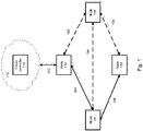
- Fig. 1 illustrates an example system 100, including a cloud controller 110 and an interconnected plurality of nodes 152-158. While only several nodes are shown, it should be understood that numerous nodes may be included.
- the nodes are interconnected with the cloud controller 110 via a link 182 and are interconnected with each other via a plurality of primary links 184-186 and alternative links 192-196.
- Network 112 may be SDWN, or any other type of network such as a datacenter, a load-balanced server farm, a backplane of interconnected peripherals, a system of components on a motherboard, etc.
- the network 112, and intervening nodes may comprise various configurations and protocols including the Internet, World Wide Web, intranets, virtual private networks, wide area networks, local networks, private networks using communication protocols proprietary to one or more companies, Ethernet, WiFi (such as 802.11, 802.11b, g, n, or other such standards), and HTTP, and various combinations of the foregoing.
- the controller may be, for example, a central cloud SDWN controller, which centrally manages routing and scheduling changes to the network.
- the controller pushes a centralized scheduling to all the connected nodes to establish possible links.
- the controller also provides each node in the network with an event profile, which identifies new routes to be implemented in case of link loss.
- the controller also updates the profile periodically. The updates may account for any link change events, such as down links, repaired links, and links having a high probability of failing.
- the profile is chosen to be adaptive and based on real-time feedback.
- the nodes 152-158 may be, for example, multi-gigabit speed wireless communications devices set up by the controller to communicate with neighboring nodes.
- Each of the nodes 152-158 runs an application, which may be used for communicating with the other nodes. For example, if node 154 identifies a failure of a particular link or combination of links, it broadcasts the failure to the other nodes in the network through the application. Assuming links 184, 186 are still active, applications running on nodes 152 and 158 will receive the broadcast "link down" information over raw sockets. The receiving nodes 152, 158 determine if they have previously broadcast the same "link down" information, and if not, the nodes 152, 158 broadcast that "link down" information to other connected nodes.
- the node 152 which is connected to the controller 110, serves as a hub node. Continuing the example above, when the node 152 receives the "link down" information, it also forwards the information to the controller 110, thereby enabling the control 110 to make future routing decisions.
- the nodes in the network will update their routing tables to implement a new routing scheme provided in the event profile. For example, upon identifying a link down event, such as by detecting that one or more links connected thereto are down or by receiving "link down" information broadcast by a connected node, the node refers to the event profile for instructions on how to handle the identified link down event.
- the event profile may indicate that the node should replace one or more paths with one or more new paths identified in the event profile.
- the nodes implementing the new routing scheme may include additional nodes in the network affected by the change, despite that those additional nodes are not directly connected to the failed link. For example, if the node 156 receives "link down" information indicating that link 184 has failed, the node 156 consults the event profile and updates its routing table accordingly.
- the primary links 184-186 may be highly directional links for mmWave physical layer communications, such as phased arrays.
- the primary links 184-186 include paths chosen by the controller 110 that route controller traffic and normal user data.
- Link level radio resource scheduling is coordinated with network level routing decisions, so that a given node is beamformed with a desired peer.
- the backhaul topology is expected to have alternate (redundant) links.
- the nodes are expected to spend only a fraction of time in these links so that they maintain the beamformed link, with a primary goal exchanging very low bandwidth control traffic.
- the alternate links 192-196 provide a possible path to the controller during primary link loss. Whether a link is considered a primary link or an alternate link may be relevant to a particular node or path. For example, a primary path from the node 152 to the node 154 may include primary link 184, while an alternate path may include alternate links 192, 194.There should be at least one alternate link active at the time of a primary link failure. Also, latency should be kept as minimal as possible to avoid delays in restoring traffic at link loss.
- the node 154 detects a failure of the primary link 186.
- An inter-node communication mechanism used by the node 154 does not rely on any specific routing. Rather, the node 154 with the failed link broadcasts a frame with a special ether type. All the nodes 152-158 are set up with a switching entry that detects the ether type, and forwards it to an application running on the node. Accordingly, applications running on the nodes 152, 156, 158 receive the broadcast frame over raw sockets, and the underlying network does not redistribute the broadcast frame. The applications running on each of the nodes 152, 156, 158 look at a specific cookie in the broadcast frame to identify if it has previously forwarded the frame. If any of the applications on the receiving nodes 152, 156, 158 has not previously forwarded the frame, that application will retransmit the frame on all available interfaces.
- the node 152 As the failed primary link 186 is also coupled to the node 152, the node 152 also detects and broadcast the link loss on all the available links contemporaneously with the node 154. In some examples, the broadcast by the node 152 includes the same cookie as the broadcast by the node 154.
- each receiving node 152, 156, 158 updates its routing table based on the event profile. For example, the node 156 receives multiple broadcast frames, each frame identifying a different failed link. Taken together, the multiple broadcast frames indicate a particular combination of failed links. In some examples, the node 156 collects one or more frames and consults the event profile for a routing update corresponding to the combination of failed links. In other examples, the node 156 consults the event profile for each individual notification received. In either case, the node 156 then updates its routing table based on a predetermined recommended response in the event profile. The other nodes 152, 158 in the network also perform the same procedure. In some examples, the nodes 152, 156, 158 may enter a temporary buffering state before moving to a forwarding state while retransmitting the broadcast frame.
- a link loss combination may not match a profile entry.
- the nodes 152-158 may stop any further forwarding of data frames, and enter a buffering mode.
- the link loss broadcast eventually reaches the controller 110 via the hub node 120 that has wired connectivity, for example via link 182, to the controller network.
- the controller 110 pushes a new route update.
- the hub node 152 broadcasts the new route update.
- the node might choose to treat that event as a link loss without a matching profile. Accordingly, the node may send a link loss event to the controller for a new route update, for example, as broadcast over all available links.
- Fig. 2 provides a more detailed depiction of the controller 110.
- the controller 110 may be any type of virtualized or non-virtualized computing device or system of computing devices capable of communicating over a network.
- Controller 110 contains one or more processors 140, memory 130 and other components typically present in general purpose computing devices.
- the memory 130 stores information accessible by the one or more processors 140, including instructions 138 that can be executed by the one or more processors 140.
- Memory 130 can also include data 134 that can be retrieved, manipulated or stored by the processor 140.
- the memory can be of any non-transitory type capable of storing information accessible by the processor, such as a hard-drive, memory card, RAM, DVD, write-capable, etc.
- the instructions 138 can be any set of instructions to be executed directly, such as machine code, or indirectly, such as scripts, by the one or more processors.
- the terms "instructions,” “applications,” “steps” and “programs” can be used interchangeably herein.
- the instructions can be stored in object code format for direct processing by a processor, or in any other computing device language including scripts or collections of independent source code modules that are interpreted on demand or compiled in advance. Functions, methods and routines of the instructions are explained in more detail below.
- Data 134 can be retrieved, stored or modified by the one or more processors 140 in accordance with the instructions 138.
- the data 134 includes one or more event profiles 136 provided to the nodes 152-158.
- the event profile 136 may be a master event profile which provides routing instructions for every node in the event of link failure.
- the event profile 136 may include a number of event profiles, such as one profile specific to each node in the network.
- the controller 110 provides the event profile 136 to the nodes in the network.
- the controller 110 further receives information from the nodes, such as information identifying links that are down or links that are likely to break.
- the controller 110 uses this information to update the event profiles.
- the updated event profiles are again provided to the nodes.
- the data 134 can be stored in internal or external memory, computer registers, in a relational database as a table having many different fields and records, or XML documents.
- the data 134 can also be formatted in any computing device-readable format such as, but not limited to, binary values, ASCII or Unicode.
- the data can comprise any information sufficient to identify the relevant information, such as numbers, descriptive text, proprietary codes, pointers, references to data stored in other memories such as at other network locations, or information that is used by a function to calculate the relevant data.
- the one or more processors 140 can be any conventional processors, such as commercially available CPUs. Alternatively, the processors can be dedicated components such as an application specific integrated circuit ("ASIC") or other hardware-based processor. Although not necessary, the server 130 may include specialized hardware components to perform specific computing processes.
- ASIC application specific integrated circuit
- Fig. 2 functionally illustrates the processor, memory, and other elements of computing device 110 as being within the same block
- the processor, computer, computing device, or memory can actually comprise multiple processors, computers, computing devices, or memories that may or may not be stored within the same physical housing.
- the memory can be a hard drive or other storage media located in housings different from that of the computing devices 110.
- references to a processor, computer, computing device, or memory will be understood to include references to a collection of processors, computers, computing devices, or memories that may or may not operate in parallel.
- the computing devices 110 may include server computing devices operating as a load-balanced server farm, distributed system, etc.
- some functions described below are indicated as taking place on a single computing device having a single processor, various aspects of the subject matter described herein can be implemented by a plurality of computing devices, for example, communicating information over a network.
- Fig. 3 provides a more detailed depiction of an example node 350.
- the node 350 is structured similarly to the controller 110, with one or more processors 380 and memory 360, including data 362 and instructions 368 as described above.
- the node 350 may be a network device, such as a server, a router, or any other type of computing device.
- the node 350 may be a personal computing device having all of the components normally used in connection with a personal computing device, such as a central processing unit (CPU), memory (e.g., RAM and internal hard drives) storing data and instructions, a display (e.g., a monitor having a screen, a touch-screen, a projector, a television, or other device that is operable to display information), user input device (e.g., a mouse, keyboard, touch-screen or microphone), and all of the components used for connecting these elements to one another.
- CPU central processing unit
- memory e.g., RAM and internal hard drives
- a display e.g., a monitor having a screen, a touch-screen, a projector, a television, or other device that is operable to display information
- user input device e.g., a mouse, keyboard, touch-screen or microphone
- the node 350 also includes one or more applications 370 executed on the node 350.
- the applications 370 are configured to perform a variety of functions, including facilitating communication among various nodes.
- the application may include a socket listening over all interfaces.
- the applications 370 makes decisions regarding whether or not to send notifications, such as broadcast frames. While the applications 370 are shown as being separate from memory 360, it should be understood that the applications may be integrated with the memory 360.
- the node 350 may include other features for inter-node communication.
- the node 350 may be equipped with ports or interfaces for L2/L3 routing.
- the node 350 stores data 362, such as an event profile 364 and a routing table 366.
- the event profile 364 may be a table or other data structure pushed by the controller 110 ( Fig. 2 ) that provides information to the node 350 in the event of link failure.
- the event profile 364 stored on the node 350 may be the same as the event profile 136 of Fig. 2 . In other examples, it may be specific to the node 350.
- the routing table 366 may be any type of routing table capable of being updated by at least one of the node 350 and the controller 110.
- the instructions 368 programmed on the node 350 enable the node 350 to identify the occurrence of a particular link down event.
- the identifying includes detection, receipt of a notification from a neighboring node, or any other technique.
- the node 350 determines whether it previously handled the link down event, and if not, communicates the event to other nodes in the network. As mentioned above, this determination and the subsequent communication may be performed by the applications 370.
- the node 350 further determines, based on the event profile 364, routing changes corresponding to the particular link loss event.
- the node 350 accordingly updates the routing table 366 based on the predetermined routing changes.
- Fig. 4 illustrates an example event profile 400.
- the event profile 400 is a table, including a plurality of columns 410 and rows 430.
- a first column 412 in each row 430 may indicate a particular link loss event.
- each cell may indicate one of many possible combinations of down links, such as a "link 1" being down, "link 1" and a "link 3" being down, etc. While only a few combinations are shown, many permutations may be included.
- the event profile 400 may include thousands of possible link loss events or more.
- each entry in the first link loss event column 412 is an entry in a column designated for a specific node.
- column 414 may identify actions to be taken by node A
- column 416 may identify actions to be taken by node B
- column 418 may indicate actions to be taken by node n, etc.
- the actions may include instructions for updating the routing table of the specific node. For example, for a link loss event in cell 435 corresponding to links 1, 5, and 7 being down, the node B may be instructed to modify one or more entries in one or more of its routing tables.
- Fig. 4 While the example event profile is shown in Fig. 4 as a table, other data structures may be used.
- Fig. 5 illustrates an example method 500 of controlling routing and updating in a network.
- the controller provides event profiles to nodes in the network.
- the controller may provide to each node in the network a master event profile indicating actions to be taken by various nodes in the event of a number of possible link failure combinations.
- the controller receives information from one or more of the nodes. For example, information from various nodes may be passed to the controller through a hub node.
- the information may indicate the status of one or more links. For example, the status may identify a link as being down or likely to fail.
- a link may be determined to be likely to fail based on, for example, current metrics such as higher error rate or decreasing signal strength. In other examples, the determination could be based on statistical analysis by the controller. For example, the controller may look at the link history to determine susceptible links and adaptively modify failure thresholds for such links to be more aggressive.
- the controller updates the event profiles based on the received information. For example, the received information may be aggregated, and collectively it may identify a combination of links likely to fail. If that combination is not already listed in the event profile, the controller may add routing changes for the nodes for that possible link loss event. The controller may further push the updated event profile to the nodes.
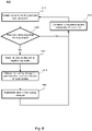
- Fig. 6 illustrates an example method 600 of updating routing topology. The method is described below from a perspective of a given node in the network. However, each node in the network may be programmed to perform the method 600.
- the node identifies the occurrence of a link loss event.
- the identifying may include detecting that one or more connected links are down, or receiving a notification from at least one of the controller and another node.
- the node receives the notification, through an application running thereon, from a neighboring node still connected through an active link.
- the link loss event may include failure or deactivation of one or a plurality of links in the network. In complex networks, a combination of links across different nodes of the network may be down at a given time.
- the node determines whether it previously communicated the link loss event to other nodes in the network. For example, the application on the given node looks at a specific cookie in a frame received from another node, the specific cookie indicating whether the given node has previously forwarded the frame. In other examples, the node may consult a log of previous transmission events.
- the node continues routing and sending information to the controller in block 625. Such information is used by the controller to update the event profile, as discussed above in connection with Fig. 5 .
- the node sends a notification to one or more neighboring nodes. For example, an application running on the node broadcasts the received frame on all interfaces.
- the node determines a routing change for the particular link loss event. Determining the routing change includes consulting the event profile to identify a predetermined action corresponding to the link loss event. In some examples, the node receives multiple notifications of link loss events. Accordingly, the node determines an appropriate update for the combination of failed links.
- the node implements the determined routing changes. For example, the node modifies one or more entries in a routing/forwarding table. The method 600 then returns to block 625 where the node continues routing, and monitoring for new link loss events.
- the systems and methods described above may operate without an additional, robust wireless technology for out-of-band access to the controller. As a result, significant cost savings and power conservation can be realized. Moreover, performance is enhanced, as local inter-node communication required to re-establish routes is expected to have better latency than a controller response.
Description
- The present application is a continuation of
U.S. Patent Application No. 14/929,991, filed November 2, 2015 - A cloud managed mmWave based point-to-multipoint mesh backhaul requires a centralized scheduling of the mmWave transmissions and reception to be fully coordinated by a central cloud SDWN (Software Defined Wireless Network) controller. Further, network level routing decisions across nodes in the network are also coordinated by the controller. This assumes reliable connectivity between the managed mmWave nodes and SDWN cloud controller. However, mmWave link technologies operate at very high radio frequencies, which typically require line-of-sight (LOS) radio paths. These LOS radio paths may be inherently less reliable than conventional radio communications systems in lower frequencies, which may be able to operate in more robust non-line-of-sight (NLOS) radio paths.
- Data path routing between nodes in the backhaul utilizes the same link paths as control path communication from the nodes to the controller, with the key assumption that no out-of-band mechanism exists for the communication to the controller. Simultaneously using the links that are managed by the controller for communication to the controller itself and for managing routing and channel scheduling updates creates a problem during the loss of an active link. During a link loss, the node loses the current established network path to the controller. Reverting back to either local or distributed routing will either run the risk of creating loops or broadcast storms in the network or is likely to require complex local distributed algorithms which create network management overhead.
- Some networks leverage out-of-band connectivity with a controller for similar use cases, so that the actively managed link is not used for connectivity with the controller. This provides a communication path with the controller whose reliability is independent of the links being managed. However, this also requires additional connectivity technology to be implemented on the nodes being managed, possibly adding hardware, software and management cost and complexity overhead to the product.
- According to Sahri N. M. et al, "Fast failover mechanism for software defined networking", Future Internee Technologies, ACM, 2 Penn Plaza, Suite 701 New York NY 10121-0701
USA, (20140618 -
EP 2 811 702 A1 describes, in an open flow network, a load of a switch on a secure channel network when a controller maintains and updates a physical topology of the switch in the situation that a network among the switches is in a high delay state. More specifically, the controller sets a flow entry having a rule and an action defined to uniformly control a packet as a flow to each of a plurality of switches. The controller sets to each switch, a circulation flow entry to be deleted when a circulation packet which is mutually transmitted and received among the switches gets not to arrive. Then, when receiving a notice that the circulation flow entry has been deleted, from each switch, the controller detects a failure among the switches. -
US 2002/150043 A1 discloses a system that facilitates instant failover during packet routing by employing a flooding protocol to send packets between a source and a destination. Upon receiving a packet containing data at an intermediate node located between the source and the destination, the system determines whether the packet has been seen before at the intermediate node. If not, the system forwards the packet to neighboring nodes of the intermediate node. In one embodiment of the present invention, forwarding the packet to neighboring needs involves forwarding the packet to all neighboring nodes except the node from which the packet was received. In one embodiment of the present invention, determining whether the packet has been seen before involves examining a sequence number, SR, contained within the packet to determine whether the sequence number has been seen before. - Objects of the present invention are achieved by the subject matters of independent claims. Dependent claims define some exemplary embodiments.
- The present disclosure highlights mechanisms applicable to cloud managed point-to-multipoint mmWave mesh backhaul enabling the controller to continue to centrally handle routing and scheduling changes to the topology during link loss. When an active link used for data path routing as well as for control path communications to the controller is disconnected, available alternate links are used. These mechanisms accommodate the highly directional nature of mmWave physical layer communications, which include, for example, high gain, narrow beam antennas, dynamic beamforming technologies such as phased arrays, etc.
- One aspect of the disclosure provides a system for managing a network as claimed in
independent claim 1. - Another aspect of the disclosure provides a method for a wireless network node as claimed in independent claim 4.
- Yet another aspect of the disclosure provides a wireless network node as claimed in claim 7.
-
-
Fig. 1 is a schematic diagram of an example system. -
Fig. 2 is a block diagram of an example controller. -
Fig. 3 is a block diagram of an example node. -
Fig. 4 illustrates an example event profile. -
Fig. 5 is a flow diagram illustrating an example method not falling in the scope of the granted claims. -
Fig. 6 is a flow diagram illustrating another example method not falling in the scope of the granted claims. - The present disclosure generally relates to managing scheduling and routing decisions in a network, such as a cloud managed mmWave based point-to-multipoint mesh backhaul. A central cloud Software Defined Wireless Network (SDWN) controller centrally manages routing and scheduling changes to the network. Each node in the network is provided with an event profile, which identifies new routes to be implemented in case of link loss, for example due to link failure or other circumstances. If a particular link or combination of links fails, applications running on the nodes connected to the failed links broadcasts the link down state. Additionally, the nodes in the network will update their routing tables to implement a new routing scheme provided in the event profile. The nodes implementing the new routing scheme may include additional nodes in the network affected by the change, despite that those additional nodes are not directly connected to the failed link.
- The network nodes may include multi-gigabit speed wireless communications devices set up by the controller to communicate with neighboring nodes. The controller pushes a centralized scheduling to all the connected nodes to establish possible links. The links are highly directional. Phased arrays are one example of highly directional link technology. Primary links include paths chosen by the controller that route controller traffic and normal user data. Link level radio resource scheduling is coordinated with network level routing decisions, so that a given node is beamformed with a desired peer. With the directional phased-arrays, the backhaul topology is expected to have alternate (redundant) links. The nodes are expected to spend only a fraction of time in these links so that they maintain the beamformed link, with a primary goal exchanging very low bandwidth control traffic. These alternate links provide a possible path to the controller during primary link loss. However, there should be at least one alternate link active at the time of primary link failure. Also, latency should be kept as minimal as possible to avoid delays in restoring traffic at link loss.
- The network includes many nodes, such as over one hundred nodes. Accordingly, the computation complexity of determining scheduling and routes for all permutations of link failure may be extremely challenging within the time constraints.
- The event profile has the routing and scheduling instructions for normal operation and for when one or more links fail. In the topology, all scheduling and routing decisions need to be well synchronized. To accommodate, the profile indicating how nodes should respond to link loss carries all permutable possibilities of link loss. The event profile may be, for example, a lookup table or other data structure which correlates a potential link loss event with a proposed node response.
- The controller also updates the profile periodically. The updates may account for any link change events. The profile is chosen to be adaptive and based on real-time feedback, taking advantage of the fact that the mmWave nodes are fixed nodes with channel conditions that are not very dynamic. The controller learns through periodic link updates about the links that have high probability of link breaks, and provides profile updates only for those permutations, thereby reducing the computational complexity that can be managed by most of the cloud implementations.
- In the case of a link loss combination that does not match a profile entry, the nodes stop any further forwarding of data frames, and enter a buffering mode. The link loss broadcast eventually reaches the controller via the hub node that has wired connectivity to the controller network, and the controller responds by pushing a new route update. The hub node is expected to broadcast the new route update by controller, given that the network route will be in an unstable state until the new route is established. In some implementations the nodes may enter a temporary buffering state for link loss events that matches a profile, to ensure route updates for all neighbors before moving to a forwarding state.
- Note that there are two nodes for a failed link. Both the nodes broadcast the link loss on all the available links, optionally with the same cookie, populated in the profile table. If the newly selected primary link also fails before a new profile is pushed by the controller, the node might choose to treat that event as a link loss without a matching profile, and send a link loss event to the controller for a new route update, again as broadcast, possibly over all available links.
- Such situations are expected to be rare and the changes are temporary until the controller turns around with an update after the link loss event reaches the controller.
- The broadcast mechanism and inter-node communication mechanism used by the node with the failed link does not rely on controller set up SDN routing, as this happens when the primary link required for routing has failed. When a particular link fails, the node with the failed link broadcasts a notification. The notification may be broadcast using any of a variety of propagation methods. According to one example, a routing mechanism may use raw sockets and special ether types, optionally using one or more nodes as a controller proxy. For example, the node with the failed link broadcasts a frame with a special ether type. All the nodes are set up with a switching entry that detects the ether type, and forwards it to the application running on the node. The application receives it over raw sockets, and the underlying network does not redistribute the broadcast frame. The receiving node chooses to re-transmit the link failure on all the available interfaces, if it has not already done a broadcast for the matching cookie within the configured duration in the past. The application looks at a specific cookie in the broadcast frame to identify if it has previously forwarded the frame, before attempting to forward it again, ensuring that there are no loops in the topology. A 'hub node' that is connected to the controller over a wired network will additionally send the broadcast frame to the controller as well, so that the controller can make future decisions.
- According to another example, standard layer 2/layer 3 (L2/L3) routing mechanisms can be used. For example, control traffic may be L2 isolated, such as in a virtual local area network (VLAN). Yet another approach is to modify standard L2/L3 routing algorithms, optimized for latency and mmWave characteristics. As an example, in an Optimized Link State Routing (OLSR) algorithm, any required behavior or parameters may be modified for faster route convergence. Moreover, broadcast latencies may also be modified for controlled, directional mmWave networks. The controller and inter-node messaging mechanism may be predetermined based on, for example, system deployment scenarios and routing characteristics of the particular network.
- Upon receiving the broadcast frame, and determining whether or not to forward it, each node updates its routing table based on the event profile. For example, a given node receives multiple broadcast frames, the frames indicating that a particular combination of links has failed. The given node consults the event profile, and identifies a predetermined recommended response corresponding to that particular combination of failed links. The given node then updates its routing table based on the predetermined recommended response. Each other node in the network also performs the same procedure.
- The techniques described above are advantageous in that they require a lower product cost and power as the product does not need an additional, robust wireless technology for out-of-band access to the controller, and possibly better performance as the local inter-node communication required to re-establish the routes are expected to have better latency than a controller response.
-
Fig. 1 illustrates an example system 100, including acloud controller 110 and an interconnected plurality of nodes 152-158. While only several nodes are shown, it should be understood that numerous nodes may be included. The nodes are interconnected with thecloud controller 110 via alink 182 and are interconnected with each other via a plurality of primary links 184-186 and alternative links 192-196. -
Network 112 may be SDWN, or any other type of network such as a datacenter, a load-balanced server farm, a backplane of interconnected peripherals, a system of components on a motherboard, etc. Thenetwork 112, and intervening nodes, may comprise various configurations and protocols including the Internet, World Wide Web, intranets, virtual private networks, wide area networks, local networks, private networks using communication protocols proprietary to one or more companies, Ethernet, WiFi (such as 802.11, 802.11b, g, n, or other such standards), and HTTP, and various combinations of the foregoing. - The controller may be, for example, a central cloud SDWN controller, which centrally manages routing and scheduling changes to the network. The controller pushes a centralized scheduling to all the connected nodes to establish possible links. The controller also provides each node in the network with an event profile, which identifies new routes to be implemented in case of link loss. The controller also updates the profile periodically. The updates may account for any link change events, such as down links, repaired links, and links having a high probability of failing. The profile is chosen to be adaptive and based on real-time feedback.
- The nodes 152-158 may be, for example, multi-gigabit speed wireless communications devices set up by the controller to communicate with neighboring nodes. Each of the nodes 152-158 runs an application, which may be used for communicating with the other nodes. For example, if
node 154 identifies a failure of a particular link or combination of links, it broadcasts the failure to the other nodes in the network through the application. Assuminglinks nodes nodes nodes - The
node 152, which is connected to thecontroller 110, serves as a hub node. Continuing the example above, when thenode 152 receives the "link down" information, it also forwards the information to thecontroller 110, thereby enabling thecontrol 110 to make future routing decisions. - The nodes in the network will update their routing tables to implement a new routing scheme provided in the event profile. For example, upon identifying a link down event, such as by detecting that one or more links connected thereto are down or by receiving "link down" information broadcast by a connected node, the node refers to the event profile for instructions on how to handle the identified link down event. The event profile may indicate that the node should replace one or more paths with one or more new paths identified in the event profile. The nodes implementing the new routing scheme may include additional nodes in the network affected by the change, despite that those additional nodes are not directly connected to the failed link. For example, if the node 156 receives "link down" information indicating that
link 184 has failed, the node 156 consults the event profile and updates its routing table accordingly. - The primary links 184-186 may be highly directional links for mmWave physical layer communications, such as phased arrays. The primary links 184-186 include paths chosen by the
controller 110 that route controller traffic and normal user data. Link level radio resource scheduling is coordinated with network level routing decisions, so that a given node is beamformed with a desired peer. With the directional phased-arrays, the backhaul topology is expected to have alternate (redundant) links. The nodes are expected to spend only a fraction of time in these links so that they maintain the beamformed link, with a primary goal exchanging very low bandwidth control traffic. These alternate links - The alternate links 192-196 provide a possible path to the controller during primary link loss. Whether a link is considered a primary link or an alternate link may be relevant to a particular node or path. For example, a primary path from the
node 152 to thenode 154 may includeprimary link 184, while an alternate path may includealternate links 192, 194.There should be at least one alternate link active at the time of a primary link failure. Also, latency should be kept as minimal as possible to avoid delays in restoring traffic at link loss. - According to one example, the
node 154 detects a failure of theprimary link 186. An inter-node communication mechanism used by thenode 154 does not rely on any specific routing. Rather, thenode 154 with the failed link broadcasts a frame with a special ether type. All the nodes 152-158 are set up with a switching entry that detects the ether type, and forwards it to an application running on the node. Accordingly, applications running on thenodes nodes nodes - As the failed
primary link 186 is also coupled to thenode 152, thenode 152 also detects and broadcast the link loss on all the available links contemporaneously with thenode 154. In some examples, the broadcast by thenode 152 includes the same cookie as the broadcast by thenode 154. - Continuing the example above, each receiving
node other nodes nodes - In some instances, a link loss combination may not match a profile entry. In this event, the nodes 152-158 may stop any further forwarding of data frames, and enter a buffering mode. The link loss broadcast eventually reaches the
controller 110 via the hub node 120 that has wired connectivity, for example vialink 182, to the controller network. In response, thecontroller 110 pushes a new route update. Thehub node 152 broadcasts the new route update. - It is possible that a newly selected primary link also fails before a new profile is pushed by the controller. In this case, the node might choose to treat that event as a link loss without a matching profile. Accordingly, the node may send a link loss event to the controller for a new route update, for example, as broadcast over all available links.
-
Fig. 2 provides a more detailed depiction of thecontroller 110. Thecontroller 110 may be any type of virtualized or non-virtualized computing device or system of computing devices capable of communicating over a network.Controller 110 contains one ormore processors 140,memory 130 and other components typically present in general purpose computing devices. Thememory 130 stores information accessible by the one ormore processors 140, includinginstructions 138 that can be executed by the one ormore processors 140. -
Memory 130 can also includedata 134 that can be retrieved, manipulated or stored by theprocessor 140. The memory can be of any non-transitory type capable of storing information accessible by the processor, such as a hard-drive, memory card, RAM, DVD, write-capable, etc. - The
instructions 138 can be any set of instructions to be executed directly, such as machine code, or indirectly, such as scripts, by the one or more processors. In that regard, the terms "instructions," "applications," "steps" and "programs" can be used interchangeably herein. The instructions can be stored in object code format for direct processing by a processor, or in any other computing device language including scripts or collections of independent source code modules that are interpreted on demand or compiled in advance. Functions, methods and routines of the instructions are explained in more detail below. -
Data 134 can be retrieved, stored or modified by the one ormore processors 140 in accordance with theinstructions 138. In one example, thedata 134 includes one or more event profiles 136 provided to the nodes 152-158. Theevent profile 136 may be a master event profile which provides routing instructions for every node in the event of link failure. In another example, theevent profile 136 may include a number of event profiles, such as one profile specific to each node in the network. - In accordance with the
instructions 138, thecontroller 110 provides theevent profile 136 to the nodes in the network. Thecontroller 110 further receives information from the nodes, such as information identifying links that are down or links that are likely to break. Thecontroller 110 uses this information to update the event profiles. The updated event profiles are again provided to the nodes. - Although the subject matter described herein is not limited by any particular data structure, the
data 134 can be stored in internal or external memory, computer registers, in a relational database as a table having many different fields and records, or XML documents. Thedata 134 can also be formatted in any computing device-readable format such as, but not limited to, binary values, ASCII or Unicode. Moreover, the data can comprise any information sufficient to identify the relevant information, such as numbers, descriptive text, proprietary codes, pointers, references to data stored in other memories such as at other network locations, or information that is used by a function to calculate the relevant data. - The one or
more processors 140 can be any conventional processors, such as commercially available CPUs. Alternatively, the processors can be dedicated components such as an application specific integrated circuit ("ASIC") or other hardware-based processor. Although not necessary, theserver 130 may include specialized hardware components to perform specific computing processes. - Although
Fig. 2 functionally illustrates the processor, memory, and other elements ofcomputing device 110 as being within the same block, the processor, computer, computing device, or memory can actually comprise multiple processors, computers, computing devices, or memories that may or may not be stored within the same physical housing. For example, the memory can be a hard drive or other storage media located in housings different from that of thecomputing devices 110. Accordingly, references to a processor, computer, computing device, or memory will be understood to include references to a collection of processors, computers, computing devices, or memories that may or may not operate in parallel. For example, thecomputing devices 110 may include server computing devices operating as a load-balanced server farm, distributed system, etc. Yet further, although some functions described below are indicated as taking place on a single computing device having a single processor, various aspects of the subject matter described herein can be implemented by a plurality of computing devices, for example, communicating information over a network. -
Fig. 3 provides a more detailed depiction of anexample node 350. In some examples, thenode 350 is structured similarly to thecontroller 110, with one ormore processors 380 andmemory 360, includingdata 362 andinstructions 368 as described above. In some examples, thenode 350 may be a network device, such as a server, a router, or any other type of computing device. In some examples, thenode 350 may be a personal computing device having all of the components normally used in connection with a personal computing device, such as a central processing unit (CPU), memory (e.g., RAM and internal hard drives) storing data and instructions, a display (e.g., a monitor having a screen, a touch-screen, a projector, a television, or other device that is operable to display information), user input device (e.g., a mouse, keyboard, touch-screen or microphone), and all of the components used for connecting these elements to one another. - The
node 350 also includes one ormore applications 370 executed on thenode 350. Theapplications 370 are configured to perform a variety of functions, including facilitating communication among various nodes. For example, the application may include a socket listening over all interfaces. Theapplications 370 makes decisions regarding whether or not to send notifications, such as broadcast frames. While theapplications 370 are shown as being separate frommemory 360, it should be understood that the applications may be integrated with thememory 360. - In some examples, the
node 350 may include other features for inter-node communication. For example, thenode 350 may be equipped with ports or interfaces for L2/L3 routing. - The
node 350stores data 362, such as anevent profile 364 and a routing table 366. Theevent profile 364 may be a table or other data structure pushed by the controller 110 (Fig. 2 ) that provides information to thenode 350 in the event of link failure. Theevent profile 364 stored on thenode 350 may be the same as theevent profile 136 ofFig. 2 . In other examples, it may be specific to thenode 350. The routing table 366 may be any type of routing table capable of being updated by at least one of thenode 350 and thecontroller 110. - The
instructions 368 programmed on thenode 350 enable thenode 350 to identify the occurrence of a particular link down event. The identifying includes detection, receipt of a notification from a neighboring node, or any other technique. Thenode 350 determines whether it previously handled the link down event, and if not, communicates the event to other nodes in the network. As mentioned above, this determination and the subsequent communication may be performed by theapplications 370. - The
node 350 further determines, based on theevent profile 364, routing changes corresponding to the particular link loss event. Thenode 350 accordingly updates the routing table 366 based on the predetermined routing changes. -
Fig. 4 illustrates anexample event profile 400. In this example, theevent profile 400 is a table, including a plurality ofcolumns 410 androws 430. Afirst column 412 in eachrow 430 may indicate a particular link loss event. For example, each cell may indicate one of many possible combinations of down links, such as a "link 1" being down, "link 1" and a "link 3" being down, etc. While only a few combinations are shown, many permutations may be included. For example, for larger networks including hundreds or thousands of nodes, theevent profile 400 may include thousands of possible link loss events or more. - Corresponding to each entry in the first link
loss event column 412 is an entry in a column designated for a specific node. For example,column 414 may identify actions to be taken by node A,column 416 may identify actions to be taken by node B,column 418 may indicate actions to be taken by node n, etc. The actions may include instructions for updating the routing table of the specific node. For example, for a link loss event incell 435 corresponding tolinks - While the example event profile is shown in
Fig. 4 as a table, other data structures may be used. - In addition to the foregoing, methods according to the present disclosure are now described. While operations of the methods are described in a particular order, it should be understood that the order of operations may be varied. Some operations may be performed simultaneously. Additionally, operations may be added or omitted.
-
Fig. 5 illustrates anexample method 500 of controlling routing and updating in a network. Inblock 510, the controller provides event profiles to nodes in the network. For example, the controller may provide to each node in the network a master event profile indicating actions to be taken by various nodes in the event of a number of possible link failure combinations. - In
block 520, the controller receives information from one or more of the nodes. For example, information from various nodes may be passed to the controller through a hub node. The information may indicate the status of one or more links. For example, the status may identify a link as being down or likely to fail. A link may be determined to be likely to fail based on, for example, current metrics such as higher error rate or decreasing signal strength. In other examples, the determination could be based on statistical analysis by the controller. For example, the controller may look at the link history to determine susceptible links and adaptively modify failure thresholds for such links to be more aggressive. - In
block 530, the controller updates the event profiles based on the received information. For example, the received information may be aggregated, and collectively it may identify a combination of links likely to fail. If that combination is not already listed in the event profile, the controller may add routing changes for the nodes for that possible link loss event. The controller may further push the updated event profile to the nodes. -
Fig. 6 illustrates anexample method 600 of updating routing topology. The method is described below from a perspective of a given node in the network. However, each node in the network may be programmed to perform themethod 600. - In
block 610, the node identifies the occurrence of a link loss event. The identifying may include detecting that one or more connected links are down, or receiving a notification from at least one of the controller and another node. For example, the node receives the notification, through an application running thereon, from a neighboring node still connected through an active link. The link loss event may include failure or deactivation of one or a plurality of links in the network. In complex networks, a combination of links across different nodes of the network may be down at a given time. - In
block 620, the node determines whether it previously communicated the link loss event to other nodes in the network. For example, the application on the given node looks at a specific cookie in a frame received from another node, the specific cookie indicating whether the given node has previously forwarded the frame. In other examples, the node may consult a log of previous transmission events. - If it is determined that the node previously transmitted a notification of the link loss event, the node continues routing and sending information to the controller in
block 625. Such information is used by the controller to update the event profile, as discussed above in connection withFig. 5 . - If the node has not previously transmitted notification of the link loss event, in
block 630 the node sends a notification to one or more neighboring nodes. For example, an application running on the node broadcasts the received frame on all interfaces. - In
block 640, the node determines a routing change for the particular link loss event. Determining the routing change includes consulting the event profile to identify a predetermined action corresponding to the link loss event. In some examples, the node receives multiple notifications of link loss events. Accordingly, the node determines an appropriate update for the combination of failed links. - In
block 650, the node implements the determined routing changes. For example, the node modifies one or more entries in a routing/forwarding table. Themethod 600 then returns to block 625 where the node continues routing, and monitoring for new link loss events. - The systems and methods described above may operate without an additional, robust wireless technology for out-of-band access to the controller. As a result, significant cost savings and power conservation can be realized. Moreover, performance is enhanced, as local inter-node communication required to re-establish routes is expected to have better latency than a controller response.
- As these and other variations and combinations of the features discussed above can be utilized without departing from the subject matter defined by the claims, the foregoing description of the embodiments should be taken by way of illustration rather than by way of limitation of the subject matter defined by the claims. As an example, the preceding operations do not have to be performed in the precise order described above. Rather, various steps can be handled in a different order or simultaneously. For example, a node detecting occurrence of a link failure and determining that the link failure has not previously been handled by the node may update its routing table prior to broadcasting notification of the link failure to other nodes. Steps can also be omitted unless otherwise stated. In addition, the provision of the examples described herein, as well as clauses phrased as "such as," "including" and the like, should not be interpreted as limiting the subject matter of the claims to the specific examples; rather, the examples are intended to illustrate only one of many possible embodiments. Further, the same reference numbers in different drawings can identify the same or similar elements.
Claims (7)
- A system (100) for managing a network (112), comprising:a plurality of wireless network nodes (152 to 158, 350) interconnected via a plurality of primary links (184 to 186) and alternate links (192 to 196), wherein a primary link includes a path chosen by a controller routing controller traffic and normal user data and wherein at least one alternate link is active at the time of link failure and provides a possible path to the controller;the controller (110) in communication with the plurality of wireless network nodes, the controller including one or more processors (140) configured to:
provide an event profile (136, 364) to the plurality of wireless network nodes, the event profile indicating routing changes to be implemented by the plurality of wireless network nodes in a variety of link loss scenarios; and wherein each of the plurality of wireless network nodes is configured to:identify that a particular link loss event occurred, wherein the identifying comprises determining, by an application running on a wireless network node, that the particular link loss event at the wireless network node itself occurred or determining the particular link loss event based on receiving a broadcast message from any neighbouring wireless network node, which informs that the particular link loss event occurred at the neighbouring wireless network node;in response to the receiving of the broadcast message, which informs thatthe particular link loss event occurred, each of the plurality of wireless network nodes is configured to:determine, by the application running on the wireless network node, whether the broadcast message with a special ether type has been previously sent by the wireless network node itself to other wireless network nodes based on a matching cookie; andif the broadcast message has not been previously sent by the wireless network node itself, broadcast the particular link loss event to the other wireless network nodes of the plurality of wireless network nodes, determine, based on the event profile, route changes for the particular link loss event, implement the determined routing changes, and continue routing and send update information to the controller. - The system of claim 1, wherein the controller is further configured to:receive information from the plurality of wireless network nodes; andupdate the event profiles based on the received information.
- The system of claim 2, wherein:the received information identifies links having a high probability of link breaks; andthe updating of the profiles accounts for scenarios where the identified links are lost.
- A method for a wireless network node (152 to 158, 350), comprising:receiving, from a controller (110) that is in communication with a plurality of wireless network nodes (152 to 158, 350), an event profile (136, 364), the event profile indicating routing changes to be implemented by the plurality of wireless network nodes in a variety of link loss scenarios, wherein the plurality of wireless network nodes are interconnected via a plurality of primary links (184 to 186) and alternate links (192 to 196), wherein a primary link includes a path chosen by the controller routing controller traffic and normal user data and wherein at least one alternate link is active at the time of link failure and provides a possible path to the controller; andidentifying, with one or more processors, that a particular link loss event occurred, wherein the identifying comprises determining, by an application running on thewireless network node, that the particular link loss event at the wireless network node itself occurred or determining the particular link loss event based on receiving a broadcast message from any neighbouring wireless network node, which informs that the particular link loss event occurred at the wireless network node;in response to the receiving of the broadcast message, which informs that the particular link loss event occurred, executing, with the one or more processors, the following:determining, by the application running on the wireless network node, whether the broadcast message with a special ether type has been previously sent by the wireless network node itself to other wireless network nodes based on a matching cookie; andif the broadcast message has not been previously sent by the wireless network node itself, broadcasting the particular link loss event to the other wireless network nodes of the plurality of wireless network nodes, determining, based on the event profile, routing changes for the particular link loss event, implementing the determined routing changes, and continuing routing and sending update information to the controller.
- The method of claim 4, further comprising:
providing information to the controller, the information indicating a status of one or more links in the network. - The method of claim 5, wherein the information identifies links having a high probability of link breaks; and optionally the method further comprises:
receiving an updated event profile from the controller in response to providing the information. - A wireless network node (152 to 158, 350), comprising:a memory (360) storing one or more routing tables; andone or more processors (380) in communication with the memory, the one or more processors programmed to:receive, from a controller (110) that is in communication with a plurality of network nodes, an event profile (136, 364), the event profile indicating routing changes to be implemented by the plurality of network nodes in a variety of link loss scenarios, wherein the plurality of wireless network nodes are interconnected via a plurality of primary links (184 to 186) and alternate links (192 to 196), and wherein a primary link includes a path chosen by the controller routing controller traffic and normal user data and wherein at least one alternate link is active at the time of link failure and provides a possible path to the controller; andidentify that a particular link loss event occurred, wherein the identifying comprises determining, by an application running on the wireless network node, that the particular link loss event at the wireless network node itself occurred or determining the particular link loss event based on receiving a broadcast message from any neighbouring wireless network node, which informs that the particular link loss event occurred at the neighbouring wireless network node;in response to the receiving of the broadcast message, which informs that the particular link loss event occurred, execute the following:determine, by the application running on the wireless network node, whether the broadcast message with a special ether type has been previously sent by the wireless network node itself to other wireless network nodes based on a matching cookie; andif the broadcast message has not been previously sent by the wireless network node itself, broadcast the particular link loss event to the other wireless network nodes of the plurality of wireless network nodes, determine, based on the event profile, routing changes for the particular link loss event, implement the determined routing changes, and continue routing and send update information to the controller.
Applications Claiming Priority (2)
| Application Number | Priority Date | Filing Date | Title |
|---|---|---|---|
| US14/929,991 US10868708B2 (en) | 2015-11-02 | 2015-11-02 | System and method for handling link loss in a network |
| PCT/US2016/058211 WO2017078948A1 (en) | 2015-11-02 | 2016-10-21 | System and method for handling link loss in a network |
Publications (3)
| Publication Number | Publication Date |
|---|---|
| EP3371940A1 EP3371940A1 (en) | 2018-09-12 |
| EP3371940A4 EP3371940A4 (en) | 2019-05-08 |
| EP3371940B1 true EP3371940B1 (en) | 2022-06-15 |
Family
ID=58635034
Family Applications (1)
| Application Number | Title | Priority Date | Filing Date |
|---|---|---|---|
| EP16862700.8A Active EP3371940B1 (en) | 2015-11-02 | 2016-10-21 | System and method for handling link loss in a network |
Country Status (9)
| Country | Link |
|---|---|
| US (1) | US10868708B2 (en) |
| EP (1) | EP3371940B1 (en) |
| JP (1) | JP6596575B2 (en) |
| KR (1) | KR102072148B1 (en) |
| CN (1) | CN107925619B (en) |
| AU (1) | AU2016348234B2 (en) |
| DE (1) | DE112016003242T5 (en) |
| GB (1) | GB2557089B (en) |
| WO (1) | WO2017078948A1 (en) |
Families Citing this family (11)
| Publication number | Priority date | Publication date | Assignee | Title |
|---|---|---|---|---|
| US9385917B1 (en) * | 2011-03-31 | 2016-07-05 | Amazon Technologies, Inc. | Monitoring and detecting causes of failures of network paths |
| US10057787B2 (en) | 2016-04-06 | 2018-08-21 | Futurewei Technologies, Inc. | System and method for millimeter wave communications |
| US10135512B2 (en) * | 2016-04-06 | 2018-11-20 | Futurewei Technologies, Inc. | System and method for millimeter wave communications |
| JP6784160B2 (en) * | 2016-12-08 | 2020-11-11 | 富士通株式会社 | Parallel processing device and inter-node communication program |
| US10367682B2 (en) * | 2017-06-30 | 2019-07-30 | Bank Of American Corporation | Node failure recovery tool |
| US10411990B2 (en) * | 2017-12-18 | 2019-09-10 | At&T Intellectual Property I, L.P. | Routing stability in hybrid software-defined networking networks |
| CN109302359A (en) * | 2018-11-27 | 2019-02-01 | 迈普通信技术股份有限公司 | A kind of network equipment, link converting method and device |
| US10958567B1 (en) * | 2019-03-29 | 2021-03-23 | Juniper Networks, Inc. | Controlling paths in a network via a centralized controller or network devices |
| US11463187B2 (en) | 2020-04-14 | 2022-10-04 | Google Llc | Fault tolerant design for clock-synchronization systems |
| US20220224638A1 (en) * | 2021-01-08 | 2022-07-14 | Hewlett Packard Enterprise Development Lp | Preventing generation of duplicate network routes in a software defined wide area network |
| JP2022110933A (en) * | 2021-01-19 | 2022-07-29 | キヤノン株式会社 | Job processing apparatus, method for controlling job processing apparatus, and program |
Citations (2)
| Publication number | Priority date | Publication date | Assignee | Title |
|---|---|---|---|---|
| US20020150043A1 (en) * | 2001-04-13 | 2002-10-17 | Perlman Radia J. | Method and apparatus for facilitating instant failover during packet routing |
| EP2811702A1 (en) * | 2012-01-30 | 2014-12-10 | NEC Corporation | Network system and topology management method |
Family Cites Families (24)
| Publication number | Priority date | Publication date | Assignee | Title |
|---|---|---|---|---|
| US5398236A (en) | 1993-05-26 | 1995-03-14 | Nec America, Inc. | Asynchronous transfer mode link recovery mechanism |
| JP2933021B2 (en) | 1996-08-20 | 1999-08-09 | 日本電気株式会社 | Communication network failure recovery method |
| US6745350B1 (en) | 1997-01-03 | 2004-06-01 | Ncr Corporation | Automated failure recovery service |
| US6392989B1 (en) * | 2000-06-15 | 2002-05-21 | Cplane Inc. | High speed protection switching in label switched networks through pre-computation of alternate routes |
| KR100813788B1 (en) | 2000-12-11 | 2008-03-13 | 주식회사 케이티 | Method for Distributing of application software using by Mobile Communication System |
| US7184401B2 (en) | 2001-02-05 | 2007-02-27 | Interdigital Technology Corporation | Link-aware transmission control protocol |
| WO2002065607A1 (en) | 2001-02-12 | 2002-08-22 | Maple Optical Systems, Inc. | Multiple level fault protection in a communications network |
| US20020171886A1 (en) | 2001-03-07 | 2002-11-21 | Quansheng Wu | Automatic control plane recovery for agile optical networks |
| US20030001079A1 (en) | 2001-04-02 | 2003-01-02 | Christian Boemler | Current mode pixel amplifier |
| JP2003018828A (en) | 2001-06-28 | 2003-01-17 | Sanken Electric Co Ltd | Dc-dc converter |
| EP1286551A1 (en) | 2001-07-17 | 2003-02-26 | Telefonaktiebolaget L M Ericsson (Publ) | Error concealment for image information |
| RU2201833C1 (en) | 2001-10-31 | 2003-04-10 | Муравьев Владимир Михайлович | Process of manufacture of skeleton columns |
| JP3594140B2 (en) | 2002-06-26 | 2004-11-24 | 沖電気工業株式会社 | Method for manufacturing semiconductor device |
| US20060005602A1 (en) | 2004-07-06 | 2006-01-12 | Zyvex Corporation | Calibration for automated microassembly |
| US8406121B2 (en) | 2004-10-20 | 2013-03-26 | Nokia Siemens Networks Gmbh & Co. Kg | Method for error detection in a packet-based message distribution system |
| WO2007035747A2 (en) * | 2005-09-19 | 2007-03-29 | Millennium It (Usa) Inc. | Scalable fault tolerant system |
| EP1821454B1 (en) * | 2006-02-17 | 2008-12-10 | Mitel Networks Corporation | Method, network and IP device for accelerating the propagation of an information concerning a detected server failure |
| US7729278B2 (en) | 2007-02-14 | 2010-06-01 | Tropos Networks, Inc. | Wireless routing based on data packet classifications |
| US7894450B2 (en) | 2007-12-31 | 2011-02-22 | Nortel Network, Ltd. | Implementation of VPNs over a link state protocol controlled ethernet network |
| US8856584B2 (en) * | 2008-08-11 | 2014-10-07 | Hitachi, Ltd. | Transport control server that modifies routing information |
| GB0905559D0 (en) | 2009-03-31 | 2009-05-13 | British Telecomm | Addressing scheme |
| JP2012049674A (en) | 2010-08-25 | 2012-03-08 | Nec Corp | Communication apparatus, communication system, communication method and communication program |
| EP2681879A1 (en) * | 2011-02-28 | 2014-01-08 | Telefonaktiebolaget LM Ericsson (PUBL) | Path computation of working and recovery paths |
| US8811212B2 (en) | 2012-02-22 | 2014-08-19 | Telefonaktiebolaget L M Ericsson (Publ) | Controller placement for fast failover in the split architecture |
-
2015
- 2015-11-02 US US14/929,991 patent/US10868708B2/en active Active
-
2016
- 2016-10-21 AU AU2016348234A patent/AU2016348234B2/en not_active Ceased
- 2016-10-21 EP EP16862700.8A patent/EP3371940B1/en active Active
- 2016-10-21 CN CN201680046715.8A patent/CN107925619B/en active Active
- 2016-10-21 WO PCT/US2016/058211 patent/WO2017078948A1/en active Application Filing
- 2016-10-21 KR KR1020187004590A patent/KR102072148B1/en active IP Right Grant
- 2016-10-21 JP JP2018507538A patent/JP6596575B2/en active Active
- 2016-10-21 GB GB1802087.5A patent/GB2557089B/en active Active
- 2016-10-21 DE DE112016003242.0T patent/DE112016003242T5/en active Pending
Patent Citations (2)
| Publication number | Priority date | Publication date | Assignee | Title |
|---|---|---|---|---|
| US20020150043A1 (en) * | 2001-04-13 | 2002-10-17 | Perlman Radia J. | Method and apparatus for facilitating instant failover during packet routing |
| EP2811702A1 (en) * | 2012-01-30 | 2014-12-10 | NEC Corporation | Network system and topology management method |
Also Published As
| Publication number | Publication date |
|---|---|
| AU2016348234B2 (en) | 2018-10-18 |
| EP3371940A1 (en) | 2018-09-12 |
| EP3371940A4 (en) | 2019-05-08 |
| DE112016003242T5 (en) | 2018-04-12 |
| GB201802087D0 (en) | 2018-03-28 |
| WO2017078948A1 (en) | 2017-05-11 |
| US10868708B2 (en) | 2020-12-15 |
| KR102072148B1 (en) | 2020-01-31 |
| AU2016348234A1 (en) | 2018-03-08 |
| GB2557089A (en) | 2018-06-13 |
| CN107925619A (en) | 2018-04-17 |
| US20170126482A1 (en) | 2017-05-04 |
| KR20180023009A (en) | 2018-03-06 |
| JP2018531535A (en) | 2018-10-25 |
| CN107925619B (en) | 2021-03-16 |
| GB2557089B (en) | 2021-11-03 |
| JP6596575B2 (en) | 2019-10-23 |
Similar Documents
| Publication | Publication Date | Title |
|---|---|---|
| EP3371940B1 (en) | System and method for handling link loss in a network | |
| EP3122004B1 (en) | Traffic switching method, device, and system | |
| JP2018531535A6 (en) | System and method for handling link loss in a network | |
| KR101700141B1 (en) | Method and apparatus for maintaining port state tables in a forwarding plane of a network element | |
| KR101099822B1 (en) | Redundant routing capabilities for a network node cluster | |
| US10148554B2 (en) | System and methods for load placement in data centers | |
| EP3474502B1 (en) | Reduced configuration for multi-stage network fabrics | |
| EP1697843B1 (en) | System and method for managing protocol network failures in a cluster system | |
| Killi et al. | Towards improving resilience of controller placement with minimum backup capacity in software defined networks | |
| JP5941404B2 (en) | Communication system, path switching method, and communication apparatus | |
| Kobo et al. | Efficient controller placement and reelection mechanism in distributed control system for software defined wireless sensor networks | |
| EP1593240B1 (en) | Method and apparatus for fast re-configuration of a network topology | |
| EP3029883B1 (en) | Network protection method and apparatus, next-ring node, and system | |
| US9876739B2 (en) | System and method for failure detection in rings | |
| CN105939254B (en) | The method and device of VRRP backup group state switching | |
| WO2014175423A1 (en) | Communication node, communication system, packet processing method and program | |
| US20150372895A1 (en) | Proactive Change of Communication Models | |
| EP3738042B1 (en) | Cloudified n-way routing protection at hyper scale | |
| WO2015040625A1 (en) | Troubleshooting openflow networks | |
| US11212204B2 (en) | Method, device and system for monitoring node survival state | |
| US9590893B2 (en) | System and method for management of network links by traffic type | |
| US10277700B2 (en) | Control plane redundancy system | |
| US7480256B2 (en) | Scalable and fault-tolerant link state routing protocol for packet-switched networks | |
| CN115396385B (en) | Method and device for quickly recovering service of stack switch and computing equipment | |
| US10855520B1 (en) | Utilizing upstream routing of multicast traffic from redundant multicast sources to increase multicast resiliency and availability |
Legal Events
| Date | Code | Title | Description |
|---|---|---|---|
| STAA | Information on the status of an ep patent application or granted ep patent |
Free format text: STATUS: THE INTERNATIONAL PUBLICATION HAS BEEN MADE |
|
| PUAI | Public reference made under article 153(3) epc to a published international application that has entered the european phase |
Free format text: ORIGINAL CODE: 0009012 |
|
| STAA | Information on the status of an ep patent application or granted ep patent |
Free format text: STATUS: REQUEST FOR EXAMINATION WAS MADE |
|
| 17P | Request for examination filed |
Effective date: 20180208 |
|
| AK | Designated contracting states |
Kind code of ref document: A1 Designated state(s): AL AT BE BG CH CY CZ DE DK EE ES FI FR GB GR HR HU IE IS IT LI LT LU LV MC MK MT NL NO PL PT RO RS SE SI SK SM TR |
|
| AX | Request for extension of the european patent |
Extension state: BA ME |
|
| DAV | Request for validation of the european patent (deleted) | ||
| DAX | Request for extension of the european patent (deleted) | ||
| A4 | Supplementary search report drawn up and despatched |
Effective date: 20190404 |
|
| RIC1 | Information provided on ipc code assigned before grant |
Ipc: H04L 12/715 20130101ALI20190329BHEP Ipc: H04L 12/751 20130101ALI20190329BHEP Ipc: H04L 12/707 20130101ALI20190329BHEP Ipc: H04L 12/721 20130101AFI20190329BHEP Ipc: H04L 12/703 20130101ALI20190329BHEP Ipc: H04L 12/26 20060101ALI20190329BHEP |
|
| STAA | Information on the status of an ep patent application or granted ep patent |
Free format text: STATUS: EXAMINATION IS IN PROGRESS |
|
| 17Q | First examination report despatched |
Effective date: 20201019 |
|
| STAA | Information on the status of an ep patent application or granted ep patent |
Free format text: STATUS: EXAMINATION IS IN PROGRESS |
|
| STAA | Information on the status of an ep patent application or granted ep patent |
Free format text: STATUS: EXAMINATION IS IN PROGRESS |
|
| GRAP | Despatch of communication of intention to grant a patent |
Free format text: ORIGINAL CODE: EPIDOSNIGR1 |
|
| STAA | Information on the status of an ep patent application or granted ep patent |
Free format text: STATUS: GRANT OF PATENT IS INTENDED |
|
| INTG | Intention to grant announced |
Effective date: 20220104 |
|
| GRAS | Grant fee paid |
Free format text: ORIGINAL CODE: EPIDOSNIGR3 |
|
| GRAA | (expected) grant |
Free format text: ORIGINAL CODE: 0009210 |
|
| STAA | Information on the status of an ep patent application or granted ep patent |
Free format text: STATUS: THE PATENT HAS BEEN GRANTED |
|
| AK | Designated contracting states |
Kind code of ref document: B1 Designated state(s): AL AT BE BG CH CY CZ DE DK EE ES FI FR GB GR HR HU IE IS IT LI LT LU LV MC MK MT NL NO PL PT RO RS SE SI SK SM TR |
|
| REG | Reference to a national code |
Ref country code: CH Ref legal event code: EP Ref country code: GB Ref legal event code: FG4D |
|
| REG | Reference to a national code |
Ref country code: IE Ref legal event code: FG4D |
|
| REG | Reference to a national code |
Ref country code: DE Ref legal event code: R096 Ref document number: 602016072904 Country of ref document: DE |
|
| REG | Reference to a national code |
Ref country code: AT Ref legal event code: REF Ref document number: 1499065 Country of ref document: AT Kind code of ref document: T Effective date: 20220715 |
|
| REG | Reference to a national code |
Ref country code: NL Ref legal event code: FP |
|
| REG | Reference to a national code |
Ref country code: LT Ref legal event code: MG9D |
|
| PG25 | Lapsed in a contracting state [announced via postgrant information from national office to epo] |
Ref country code: SE Free format text: LAPSE BECAUSE OF FAILURE TO SUBMIT A TRANSLATION OF THE DESCRIPTION OR TO PAY THE FEE WITHIN THE PRESCRIBED TIME-LIMIT Effective date: 20220615 Ref country code: NO Free format text: LAPSE BECAUSE OF FAILURE TO SUBMIT A TRANSLATION OF THE DESCRIPTION OR TO PAY THE FEE WITHIN THE PRESCRIBED TIME-LIMIT Effective date: 20220915 Ref country code: LT Free format text: LAPSE BECAUSE OF FAILURE TO SUBMIT A TRANSLATION OF THE DESCRIPTION OR TO PAY THE FEE WITHIN THE PRESCRIBED TIME-LIMIT Effective date: 20220615 Ref country code: HR Free format text: LAPSE BECAUSE OF FAILURE TO SUBMIT A TRANSLATION OF THE DESCRIPTION OR TO PAY THE FEE WITHIN THE PRESCRIBED TIME-LIMIT Effective date: 20220615 Ref country code: GR Free format text: LAPSE BECAUSE OF FAILURE TO SUBMIT A TRANSLATION OF THE DESCRIPTION OR TO PAY THE FEE WITHIN THE PRESCRIBED TIME-LIMIT Effective date: 20220916 Ref country code: FI Free format text: LAPSE BECAUSE OF FAILURE TO SUBMIT A TRANSLATION OF THE DESCRIPTION OR TO PAY THE FEE WITHIN THE PRESCRIBED TIME-LIMIT Effective date: 20220615 Ref country code: BG Free format text: LAPSE BECAUSE OF FAILURE TO SUBMIT A TRANSLATION OF THE DESCRIPTION OR TO PAY THE FEE WITHIN THE PRESCRIBED TIME-LIMIT Effective date: 20220915 |
|
| REG | Reference to a national code |
Ref country code: AT Ref legal event code: MK05 Ref document number: 1499065 Country of ref document: AT Kind code of ref document: T Effective date: 20220615 |
|
| PG25 | Lapsed in a contracting state [announced via postgrant information from national office to epo] |
Ref country code: RS Free format text: LAPSE BECAUSE OF FAILURE TO SUBMIT A TRANSLATION OF THE DESCRIPTION OR TO PAY THE FEE WITHIN THE PRESCRIBED TIME-LIMIT Effective date: 20220615 Ref country code: LV Free format text: LAPSE BECAUSE OF FAILURE TO SUBMIT A TRANSLATION OF THE DESCRIPTION OR TO PAY THE FEE WITHIN THE PRESCRIBED TIME-LIMIT Effective date: 20220615 |
|
| PG25 | Lapsed in a contracting state [announced via postgrant information from national office to epo] |
Ref country code: SM Free format text: LAPSE BECAUSE OF FAILURE TO SUBMIT A TRANSLATION OF THE DESCRIPTION OR TO PAY THE FEE WITHIN THE PRESCRIBED TIME-LIMIT Effective date: 20220615 Ref country code: SK Free format text: LAPSE BECAUSE OF FAILURE TO SUBMIT A TRANSLATION OF THE DESCRIPTION OR TO PAY THE FEE WITHIN THE PRESCRIBED TIME-LIMIT Effective date: 20220615 Ref country code: RO Free format text: LAPSE BECAUSE OF FAILURE TO SUBMIT A TRANSLATION OF THE DESCRIPTION OR TO PAY THE FEE WITHIN THE PRESCRIBED TIME-LIMIT Effective date: 20220615 Ref country code: PT Free format text: LAPSE BECAUSE OF FAILURE TO SUBMIT A TRANSLATION OF THE DESCRIPTION OR TO PAY THE FEE WITHIN THE PRESCRIBED TIME-LIMIT Effective date: 20221017 Ref country code: ES Free format text: LAPSE BECAUSE OF FAILURE TO SUBMIT A TRANSLATION OF THE DESCRIPTION OR TO PAY THE FEE WITHIN THE PRESCRIBED TIME-LIMIT Effective date: 20220615 Ref country code: EE Free format text: LAPSE BECAUSE OF FAILURE TO SUBMIT A TRANSLATION OF THE DESCRIPTION OR TO PAY THE FEE WITHIN THE PRESCRIBED TIME-LIMIT Effective date: 20220615 Ref country code: CZ Free format text: LAPSE BECAUSE OF FAILURE TO SUBMIT A TRANSLATION OF THE DESCRIPTION OR TO PAY THE FEE WITHIN THE PRESCRIBED TIME-LIMIT Effective date: 20220615 Ref country code: AT Free format text: LAPSE BECAUSE OF FAILURE TO SUBMIT A TRANSLATION OF THE DESCRIPTION OR TO PAY THE FEE WITHIN THE PRESCRIBED TIME-LIMIT Effective date: 20220615 |
|
| PG25 | Lapsed in a contracting state [announced via postgrant information from national office to epo] |
Ref country code: PL Free format text: LAPSE BECAUSE OF FAILURE TO SUBMIT A TRANSLATION OF THE DESCRIPTION OR TO PAY THE FEE WITHIN THE PRESCRIBED TIME-LIMIT Effective date: 20220615 Ref country code: IS Free format text: LAPSE BECAUSE OF FAILURE TO SUBMIT A TRANSLATION OF THE DESCRIPTION OR TO PAY THE FEE WITHIN THE PRESCRIBED TIME-LIMIT Effective date: 20221015 |
|
| REG | Reference to a national code |
Ref country code: DE Ref legal event code: R097 Ref document number: 602016072904 Country of ref document: DE |
|
| PG25 | Lapsed in a contracting state [announced via postgrant information from national office to epo] |
Ref country code: AL Free format text: LAPSE BECAUSE OF FAILURE TO SUBMIT A TRANSLATION OF THE DESCRIPTION OR TO PAY THE FEE WITHIN THE PRESCRIBED TIME-LIMIT Effective date: 20220615 |
|
| PLBE | No opposition filed within time limit |
Free format text: ORIGINAL CODE: 0009261 |
|
| STAA | Information on the status of an ep patent application or granted ep patent |
Free format text: STATUS: NO OPPOSITION FILED WITHIN TIME LIMIT |
|
| PG25 | Lapsed in a contracting state [announced via postgrant information from national office to epo] |
Ref country code: DK Free format text: LAPSE BECAUSE OF FAILURE TO SUBMIT A TRANSLATION OF THE DESCRIPTION OR TO PAY THE FEE WITHIN THE PRESCRIBED TIME-LIMIT Effective date: 20220615 |
|
| 26N | No opposition filed |
Effective date: 20230316 |
|
| PG25 | Lapsed in a contracting state [announced via postgrant information from national office to epo] |
Ref country code: SI Free format text: LAPSE BECAUSE OF FAILURE TO SUBMIT A TRANSLATION OF THE DESCRIPTION OR TO PAY THE FEE WITHIN THE PRESCRIBED TIME-LIMIT Effective date: 20220615 Ref country code: MC Free format text: LAPSE BECAUSE OF FAILURE TO SUBMIT A TRANSLATION OF THE DESCRIPTION OR TO PAY THE FEE WITHIN THE PRESCRIBED TIME-LIMIT Effective date: 20220615 |
|
| REG | Reference to a national code |
Ref country code: CH Ref legal event code: PL |
|
| P01 | Opt-out of the competence of the unified patent court (upc) registered |
Effective date: 20230505 |
|
| REG | Reference to a national code |
Ref country code: BE Ref legal event code: MM Effective date: 20221031 |
|
| GBPC | Gb: european patent ceased through non-payment of renewal fee |
Effective date: 20221021 |
|
| PG25 | Lapsed in a contracting state [announced via postgrant information from national office to epo] |
Ref country code: LU Free format text: LAPSE BECAUSE OF NON-PAYMENT OF DUE FEES Effective date: 20221021 |
|
| PG25 | Lapsed in a contracting state [announced via postgrant information from national office to epo] |
Ref country code: LI Free format text: LAPSE BECAUSE OF NON-PAYMENT OF DUE FEES Effective date: 20221031 Ref country code: FR Free format text: LAPSE BECAUSE OF NON-PAYMENT OF DUE FEES Effective date: 20221031 Ref country code: CH Free format text: LAPSE BECAUSE OF NON-PAYMENT OF DUE FEES Effective date: 20221031 |
|
| PG25 | Lapsed in a contracting state [announced via postgrant information from national office to epo] |
Ref country code: BE Free format text: LAPSE BECAUSE OF NON-PAYMENT OF DUE FEES Effective date: 20221031 |
|
| PG25 | Lapsed in a contracting state [announced via postgrant information from national office to epo] |
Ref country code: IE Free format text: LAPSE BECAUSE OF NON-PAYMENT OF DUE FEES Effective date: 20221021 Ref country code: GB Free format text: LAPSE BECAUSE OF NON-PAYMENT OF DUE FEES Effective date: 20221021 |
|
| PGFP | Annual fee paid to national office [announced via postgrant information from national office to epo] |
Ref country code: NL Payment date: 20231026 Year of fee payment: 8 |
|
| PG25 | Lapsed in a contracting state [announced via postgrant information from national office to epo] |
Ref country code: IT Free format text: LAPSE BECAUSE OF FAILURE TO SUBMIT A TRANSLATION OF THE DESCRIPTION OR TO PAY THE FEE WITHIN THE PRESCRIBED TIME-LIMIT Effective date: 20220615 |
|
| PGFP | Annual fee paid to national office [announced via postgrant information from national office to epo] |
Ref country code: DE Payment date: 20231027 Year of fee payment: 8 |
|
| PG25 | Lapsed in a contracting state [announced via postgrant information from national office to epo] |
Ref country code: HU Free format text: LAPSE BECAUSE OF FAILURE TO SUBMIT A TRANSLATION OF THE DESCRIPTION OR TO PAY THE FEE WITHIN THE PRESCRIBED TIME-LIMIT; INVALID AB INITIO Effective date: 20161021 |