EP3371884B1 - Procédé de fabrication d'un étage d'amplification d'un signal à enveloppe variable et étage d'amplification de puissance - Google Patents
Procédé de fabrication d'un étage d'amplification d'un signal à enveloppe variable et étage d'amplification de puissance Download PDFInfo
- Publication number
- EP3371884B1 EP3371884B1 EP16790381.4A EP16790381A EP3371884B1 EP 3371884 B1 EP3371884 B1 EP 3371884B1 EP 16790381 A EP16790381 A EP 16790381A EP 3371884 B1 EP3371884 B1 EP 3371884B1
- Authority
- EP
- European Patent Office
- Prior art keywords
- amplifier
- pin
- power
- value
- average
- Prior art date
- Legal status (The legal status is an assumption and is not a legal conclusion. Google has not performed a legal analysis and makes no representation as to the accuracy of the status listed.)
- Active
Links
Images

Classifications
-
- H—ELECTRICITY
- H03—ELECTRONIC CIRCUITRY
- H03F—AMPLIFIERS
- H03F1/00—Details of amplifiers with only discharge tubes, only semiconductor devices or only unspecified devices as amplifying elements
- H03F1/56—Modifications of input or output impedances, not otherwise provided for
-
- H—ELECTRICITY
- H03—ELECTRONIC CIRCUITRY
- H03F—AMPLIFIERS
- H03F1/00—Details of amplifiers with only discharge tubes, only semiconductor devices or only unspecified devices as amplifying elements
- H03F1/02—Modifications of amplifiers to raise the efficiency, e.g. gliding Class A stages, use of an auxiliary oscillation
- H03F1/0205—Modifications of amplifiers to raise the efficiency, e.g. gliding Class A stages, use of an auxiliary oscillation in transistor amplifiers
- H03F1/0211—Modifications of amplifiers to raise the efficiency, e.g. gliding Class A stages, use of an auxiliary oscillation in transistor amplifiers with control of the supply voltage or current
-
- H—ELECTRICITY
- H03—ELECTRONIC CIRCUITRY
- H03F—AMPLIFIERS
- H03F1/00—Details of amplifiers with only discharge tubes, only semiconductor devices or only unspecified devices as amplifying elements
- H03F1/02—Modifications of amplifiers to raise the efficiency, e.g. gliding Class A stages, use of an auxiliary oscillation
- H03F1/0205—Modifications of amplifiers to raise the efficiency, e.g. gliding Class A stages, use of an auxiliary oscillation in transistor amplifiers
- H03F1/0277—Selecting one or more amplifiers from a plurality of amplifiers
-
- H—ELECTRICITY
- H03—ELECTRONIC CIRCUITRY
- H03F—AMPLIFIERS
- H03F1/00—Details of amplifiers with only discharge tubes, only semiconductor devices or only unspecified devices as amplifying elements
- H03F1/02—Modifications of amplifiers to raise the efficiency, e.g. gliding Class A stages, use of an auxiliary oscillation
- H03F1/04—Modifications of amplifiers to raise the efficiency, e.g. gliding Class A stages, use of an auxiliary oscillation in discharge-tube amplifiers
- H03F1/06—Modifications of amplifiers to raise the efficiency, e.g. gliding Class A stages, use of an auxiliary oscillation in discharge-tube amplifiers to raise the efficiency of amplifying modulated radio frequency waves; to raise the efficiency of amplifiers acting also as modulators
-
- H—ELECTRICITY
- H03—ELECTRONIC CIRCUITRY
- H03F—AMPLIFIERS
- H03F1/00—Details of amplifiers with only discharge tubes, only semiconductor devices or only unspecified devices as amplifying elements
- H03F1/32—Modifications of amplifiers to reduce non-linear distortion
- H03F1/3241—Modifications of amplifiers to reduce non-linear distortion using predistortion circuits
-
- H—ELECTRICITY
- H03—ELECTRONIC CIRCUITRY
- H03F—AMPLIFIERS
- H03F3/00—Amplifiers with only discharge tubes or only semiconductor devices as amplifying elements
- H03F3/189—High-frequency amplifiers, e.g. radio frequency amplifiers
-
- H—ELECTRICITY
- H03—ELECTRONIC CIRCUITRY
- H03F—AMPLIFIERS
- H03F3/00—Amplifiers with only discharge tubes or only semiconductor devices as amplifying elements
- H03F3/189—High-frequency amplifiers, e.g. radio frequency amplifiers
- H03F3/19—High-frequency amplifiers, e.g. radio frequency amplifiers with semiconductor devices only
-
- H—ELECTRICITY
- H03—ELECTRONIC CIRCUITRY
- H03F—AMPLIFIERS
- H03F3/00—Amplifiers with only discharge tubes or only semiconductor devices as amplifying elements
- H03F3/20—Power amplifiers, e.g. Class B amplifiers, Class C amplifiers
- H03F3/21—Power amplifiers, e.g. Class B amplifiers, Class C amplifiers with semiconductor devices only
- H03F3/211—Power amplifiers, e.g. Class B amplifiers, Class C amplifiers with semiconductor devices only using a combination of several amplifiers
-
- H—ELECTRICITY
- H03—ELECTRONIC CIRCUITRY
- H03F—AMPLIFIERS
- H03F3/00—Amplifiers with only discharge tubes or only semiconductor devices as amplifying elements
- H03F3/20—Power amplifiers, e.g. Class B amplifiers, Class C amplifiers
- H03F3/22—Power amplifiers, e.g. Class B amplifiers, Class C amplifiers with tubes only
-
- H—ELECTRICITY
- H03—ELECTRONIC CIRCUITRY
- H03F—AMPLIFIERS
- H03F3/00—Amplifiers with only discharge tubes or only semiconductor devices as amplifying elements
- H03F3/20—Power amplifiers, e.g. Class B amplifiers, Class C amplifiers
- H03F3/24—Power amplifiers, e.g. Class B amplifiers, Class C amplifiers of transmitter output stages
- H03F3/245—Power amplifiers, e.g. Class B amplifiers, Class C amplifiers of transmitter output stages with semiconductor devices only
-
- H—ELECTRICITY
- H03—ELECTRONIC CIRCUITRY
- H03F—AMPLIFIERS
- H03F3/00—Amplifiers with only discharge tubes or only semiconductor devices as amplifying elements
- H03F3/54—Amplifiers using transit-time effect in tubes or semiconductor devices
- H03F3/58—Amplifiers using transit-time effect in tubes or semiconductor devices using travelling-wave tubes
-
- H—ELECTRICITY
- H03—ELECTRONIC CIRCUITRY
- H03F—AMPLIFIERS
- H03F2200/00—Indexing scheme relating to amplifiers
- H03F2200/102—A non-specified detector of a signal envelope being used in an amplifying circuit
-
- H—ELECTRICITY
- H03—ELECTRONIC CIRCUITRY
- H03F—AMPLIFIERS
- H03F2200/00—Indexing scheme relating to amplifiers
- H03F2200/462—Indexing scheme relating to amplifiers the current being sensed
-
- H—ELECTRICITY
- H03—ELECTRONIC CIRCUITRY
- H03F—AMPLIFIERS
- H03F2200/00—Indexing scheme relating to amplifiers
- H03F2200/465—Power sensing
-
- H—ELECTRICITY
- H03—ELECTRONIC CIRCUITRY
- H03F—AMPLIFIERS
- H03F2200/00—Indexing scheme relating to amplifiers
- H03F2200/471—Indexing scheme relating to amplifiers the voltage being sensed
-
- H—ELECTRICITY
- H03—ELECTRONIC CIRCUITRY
- H03F—AMPLIFIERS
- H03F2203/00—Indexing scheme relating to amplifiers with only discharge tubes or only semiconductor devices as amplifying elements covered by H03F3/00
- H03F2203/20—Indexing scheme relating to power amplifiers, e.g. Class B amplifiers, Class C amplifiers
- H03F2203/21—Indexing scheme relating to power amplifiers, e.g. Class B amplifiers, Class C amplifiers with semiconductor devices only
- H03F2203/211—Indexing scheme relating to power amplifiers, e.g. Class B amplifiers, Class C amplifiers with semiconductor devices only using a combination of several amplifiers
- H03F2203/21106—An input signal being distributed in parallel over the inputs of a plurality of power amplifiers
-
- H—ELECTRICITY
- H03—ELECTRONIC CIRCUITRY
- H03F—AMPLIFIERS
- H03F2203/00—Indexing scheme relating to amplifiers with only discharge tubes or only semiconductor devices as amplifying elements covered by H03F3/00
- H03F2203/20—Indexing scheme relating to power amplifiers, e.g. Class B amplifiers, Class C amplifiers
- H03F2203/21—Indexing scheme relating to power amplifiers, e.g. Class B amplifiers, Class C amplifiers with semiconductor devices only
- H03F2203/211—Indexing scheme relating to power amplifiers, e.g. Class B amplifiers, Class C amplifiers with semiconductor devices only using a combination of several amplifiers
- H03F2203/21142—Output signals of a plurality of power amplifiers are parallel combined to a common output
Definitions
- the invention relates to a method for manufacturing a power amplification stage of a variable envelope input signal having a predetermined statistical distribution of instantaneous power, this amplification stage delivering a predetermined average output power POUT and comprising at least one amplifier and adaptation circuits determining adjustment parameters (for example chosen for solid-state circuits from bias voltages, the complex value of the load impedance, etc.; or for traveling wave tubes from the beam current, the helix voltage, the collector voltages, etc.) whose value influences transfer functions in average power POUT(PIN), in phase PM(PIN), and in consumption PDC(PIN), of the amplification stage. It extends to an amplification stage thus manufactured.
- adjustment parameters for example chosen for solid-state circuits from bias voltages, the complex value of the load impedance, etc.; or for traveling wave tubes from the beam current, the helix voltage, the collector voltages, etc.
- the first linearization methods are not always usable, for example when there is no inverse function of the model applying to the nonlinear circuit.
- the inverse function of the modeling of the HPA power characteristic presents, by principle, a singularity in the vicinity of saturation, since its slope tends to infinity.
- they are most often extremely complex and difficult to implement and/or dedicated to specific categories of nonlinear circuits or to very specific and/or imprecise applications by nature (i.e. not producing results of sufficient quality given the approximations provided by the modeling). They require extremely heavy computing and energy resources, not necessarily available (for example on board a space system).
- some models are only applicable to traveling wave tube amplifiers, but not to solid state circuits.
- the second linearization methods induce extremely high optimization costs and are also imperfect insofar as it is not certain in advance to be able to find by successive iterations an adjustment of the different characteristics of the parameterizable pre-distortion circuit effectively allowing to empirically obtain an appropriate response at the output of the non-linear circuit.
- US 2012/0105150 describes a method of controlling an amplification system in which the bias and supply voltages are modulated instantaneously as a function of signals derived from the envelope voltage of the input signal.
- This circuit requires an envelope detector, and a voltage selection stage which generates the supply voltage and the bias voltage to be applied to the amplification stage.
- Nonlinear mapping elements make it possible to define the values of the supply voltage and the bias voltage as a function of the envelope of the input signal, for example according to a polynomial expansion of order 3 and/or by tables of values established by characterization of the device.
- US 2015/0236729 also describes a method and apparatus for dynamically optimizing in real time an amplification stage by envelope detection of the input signal.
- this circuit necessarily integrates an envelope detection system (“envelope tracking” (ET)).
- envelope tracking envelope tracking
- the problem which therefore arises for the manufacture of a power amplification stage of a signal with variable envelope, such as a microwave communication signal consists in optimizing the settings of the adaptation circuits to obtain responses as linear as possible with simultaneously optimal values of optimization criteria such as the average output power and/or the efficiency and/or the consumption and/or the dissipated power.
- optimization criteria such as the average output power and/or the efficiency and/or the consumption and/or the dissipated power.
- this optimization consists in determining the characteristics of the load impedance and the polarization of each transistor, each of these two parameters generally having two variables (gate voltage and drain voltage for a FET field effect transistor; real and imaginary parts of the load impedance).
- the publication " Optimization criteria for power amplifiers”, J. Sombrin, International Journal of Microwave and Wireless Technologies, Vol. 3, Issue 1, pp. 35-45, 2011 thus mentions different criteria which can theoretically be advantageously used for the optimization of power amplifiers.
- the invention which is described by the content of the independent claims, aims to overcome these drawbacks by proposing a method for better optimizing the adjustment parameters of an amplification stage, and this in a faster, simpler and more systematic manner, which is applicable with various amplifier technologies and various input signals, including communication signals, particularly in the microwave range (300 MHz to 300 GHz).
- the invention also aims to propose such a method which can be implemented simply, with traditional installations and devices, and which does not modify working habits.
- variable envelope signal refers to any signal exhibiting a time-varying amplitude at a predetermined frequency corresponding to the minimum frequency of the signal.
- the use of the statistical distribution of instantaneous power of the variable envelope input signal in a method according to the invention makes it possible to calculate the value of an optimization criterion and to choose adjustment parameters representing an optimization of this optimization criterion, while retaining freedom to select an ideal form of variation in average power, a selection which can be carried out in particular according to at least one performance criterion of the amplification stage, for example a predetermined value of the signal/noise ratio and/or the intermodulation rate.
- the invention is thus based on an approach that is completely different from that of the prior art, using the predetermined statistical distribution of instantaneous power of the variable envelope input signal to manufacture the adaptation circuits directly optimized to this distribution.
- the adaptation circuits being manufactured so as to provide said optimal values of the adjustment parameters, the amplification stage thus manufactured according to the invention requires neither an envelope detector of the input signal, nor a circuit allowing the dynamic adjustment in real time of supply or bias voltages.
- the optimization criterion is chosen from the average output power POUTk of the amplifier (k being throughout the text an index associated, when necessary, with each amplifier k of the amplification stage); the consumption PDCk of the amplifier; the dissipated power DISSk by the amplifier; and an efficiency of the amplifier determined by the ratio between the average output power POUTk and the consumption PDCk; and their combinations.
- the optimal value of each adjustment parameter is then chosen so as to maximize the average output power POUTk, or minimize the consumption PDCk, or minimize the dissipated power DISSk or maximize the efficiency.
- At least one optimization parameter is chosen from the average output power POUTk of the amplifier and the consumption PDCk of the amplifier, each value of the optimization criterion being calculated as a function of the mathematical expectation, with the statistical distribution of the input signal, of this optimization parameter from at least said ideal variation in average power POUT L (PIN). If the average output power POUTk is chosen as an optimization criterion, only this average output power can be used as an optimization parameter, and only the mathematical expectation of the average output power can be calculated according to the ideal variation in average power POUT L (PIN) with the statistical distribution of the input signal.
- the consumption PDCk is chosen as an optimization criterion, only the consumption can be used as an optimization parameter, and only the mathematical expectation of the consumption PDCk can be calculated, an ideal variation PDC L (PIN) of which can be determined from the ideal variation in average power POUT L (PIN).
- PIN ideal variation in average power POUT L
- both the average output power POUTk and the consumption PDCk are used as optimization parameters, for which the difference in mathematical expectations is calculated.
- the efficiency is chosen as the optimization criterion, both the average output power POUTk and the consumption PDCk are used as optimization parameters, for which the ratio of mathematical expectations is calculated.
- the invention comprises a step of characterizing each amplifier, using a test bench measuring and recording, for each value of each adjustment parameter, characteristic variations, as a function of the average input power PIN, of the phase shift PMcw(PIN) of the amplifier from the constant envelope input signal, and the adaptation circuits are chosen to obtain a phase shift of predetermined value, in particular zero.
- said ideal variation form in average power POUT L is an affine variation - in particular linear - up to a higher saturation start value.
- a linear variation is advantageously chosen having a predetermined performance at the saturation point, for example a predetermined signal-to-noise ratio, for example of the order of 15 dB, or a predetermined intermodulation rate or other. It should be noted that this predetermined performance always remains the same regardless of the values of the adjustment parameters.
- a linear variation is advantageously chosen having a curvature at the start of saturation so as to be differentiable at all points, including at the saturation point.
- variable envelope input signal having a predetermined statistical distribution of instantaneous power
- the variable envelope input signal has a probability density of instantaneous power of the input signal determined as a function of the modulation scheme of the communication signal. Indeed, it turns out that any modulated signal has a probability density of the instantaneous power which is characteristic of the modulation scheme.
- the invention nevertheless applies more generally to any variable envelope input signal having a statistical distribution of instantaneous power making it possible to determine a probability density of the instantaneous power, and to calculate a mathematical expectation of the average power for this signal.
- the inventor has thus demonstrated that the statistical distribution of the input signal can be used to calculate the mathematical expectation of an optimization parameter from the ideal variation in average power POUT L (PIN) of the amplified output signal, and that, unexpectedly, this mathematical expectation is in fact very relevant for evaluating, in a simple but very precise way, an optimization criterion of the amplifier.
- said ideal variation shape in average power POUT L is chosen as a function of a performance criterion of the amplification stage chosen from a value of a signal/noise ratio and an intermodulation rate.
- Other performance criteria may be used as a variant.
- the invention also applies more particularly, although not exclusively, advantageously to a microwave input signal, in particular to a modulated input signal comprising one (or more) carrier(s) having a carrier frequency in a frequency band which can be chosen in the microwave range (300 MHz to 300 GHz), or outside this range.
- At least one amplifier being a transistor
- said adjustment parameters are chosen from the group formed by at least one bias voltage and at least one load impedance characteristic.
- the adjustment parameters are the gate voltage, the drain voltage, the real part of the load impedance and the imaginary part of the load impedance (or the power factor ⁇ ).
- At least one amplifier being a traveling wave tube
- said adjustment parameters are chosen from the group formed by a beam current, a helix voltage, and a collector voltage.
- the amplification stage can be manufactured with one (or more) amplifier(s) in parallel.
- the amplification stage can be manufactured with one (or more) amplifier(s) in parallel.
- a plurality of identical amplifiers are advantageously used.
- the amplification stage delivering a predetermined average output power POUT, for each amplifier, an average output power value POUTk of the amplifier is determined for the optimal values of each adjustment parameter, and the number N of amplifier(s) in parallel with the amplification stage is chosen such that: ⁇ 1 N ⁇ 1 POUTk ⁇ POUT ⁇ ⁇ 1 N POUTk
- the average output power POUTk of each amplifier is advantageously calculated from the mathematical expectation of the average output power of each amplifier calculated as indicated previously.
- An amplification stage according to the invention may in particular be free of an envelope detector for the input signal and of any circuit making it possible to dynamically adjust the bias and supply voltages of the amplifier.
- the invention also relates to a method of manufacturing a power amplification stage of a variable envelope input signal, and such an amplification stage characterized in combination by all or part of the characteristics mentioned above or below.
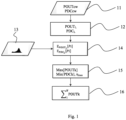
- a method of manufacturing an amplifier stage shown figure 1 comprises a first step 11 of characterizing each amplifier 12 of the amplification stage.
- an amplifier 32 formed of a field effect transistor is placed in a test bench (not shown) of the type designated in English “load pull”, for example as described by the publication “ Power characterization at millimeter frequencies of nanometric circuits in silicon technology » M. de Matos, E. Kerhervé, H. Lapuyade, JB. Bégueret, Y. Deval, 10th CNFM educational days (CNFM 2008), Nov 2008, St Malo, France. pp.111-116 .
- the values of the drain bias voltages Vd and gate bias voltages Vg and the actual value of the load impedance Z and its power factor ⁇ are varied.
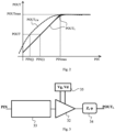
- a linearization circuit 33 is chosen, placed upstream of the amplifier 32 and capable of providing an ideal form of variation in average output power POUT L (PIN) derivable at any point.
- this ideal variation POUT L is a variation comprising a first linear part (affine in reality) up to a maximum value POUTmax of saturation of the average output power of the amplifier, with a curved transition derivable at any point between the linear part and the saturation part.
- Other examples are possible, and there are many adaptation circuits allowing to obtain various forms of ideal variation of the average output power of the amplifier.
- this linearization circuit 33 is chosen to obtain an ideal variation in average output power as a function of a performance criterion that is desired to be imposed on the amplifier, for example a value of the signal/noise ratio or an intermodulation rate at the maximum saturation power, and which is known to be satisfied for said ideal variation.
- a performance criterion for example a value of the signal/noise ratio or an intermodulation rate at the maximum saturation power, and which is known to be satisfied for said ideal variation.
- the linearization circuit 33 it is known in particular that it is possible to obtain a value of the signal-to-noise ratio at the saturation power which is for example equal to 15 dB by choosing the linearization circuit 33 appropriately.
- the linearization circuit 33 is chosen so as to obtain a phase shift of predetermined value, preferably zero, in the amplified output signal.
- a method for selecting such a linearization circuit 33 is described in the French patent application FR1453773 . Many other known variants of linearization can be used for this purpose.
- the characteristics of the electronic circuits allowing the chosen variation form to be obtained can be determined in the case of a microwave signal, in particular as described by CWPark, et al., "An Independently Controllable AM/AM and AM/PM Predistortion Linearizer for CDMA 2000 Multi-Carrier Applications", IEEE 2001 .
- a parameterizable linearizer circuit such as the Lintech (US) WAFL series linearizers, may also be used, compatible with the frequency range and the average power range intended for the input signal, and for which the variations of the transfer functions (or “curves") in average power and phase shift that it produces are predetermined and known for different values of the adjustable parameters of this parameterizable linearizer circuit.
- a set of parameters of the linearizer circuit is chosen so that the transfer functions in average power and phase shift produced by this linearizer circuit correspond as closely as possible to the desired ideal variation.
- the choice of a set of adjustable parameters of the linearizer circuit therefore makes it possible to choose an ideal variation in average power POUT L (PIN) derivable at any point.
- this ideal variation in average output power POUT L (PIN) is represented by an additional column of values of the average output power POUT L according to this ideal variation in the table mentioned above.
- the ideal variation in average power POUT L (PIN) has been selected, it is possible, if consumption is chosen as an optimization parameter, to recalculate, for each value of each adjustment parameter Vg, Vd, Z, ⁇ , an ideal variation in consumption PDC L (PIN) as a function of the average input power PIN, from said ideal variation in average power POUT L (PIN) and said measured variations POUTcw(PIN) and PDCcw(PIN).
- the aforementioned table relates the values of the measured consumption for the constant envelope signal PDCcw as a function of the values of the output power measured for the constant envelope signal POUTcw.
- PDC L (i) POUT L i ⁇ POUTcw I ⁇ POUTcw I ⁇ 1 / PDCcw I ⁇ PDCcw I ⁇ 1 with j the selected line such that: POUTcw I ⁇ POUT L i ⁇ POUTcw I ⁇ 1
- step 13 figure 1 the statistical distribution of instantaneous power of the variable envelope input signal to be amplified, which is predetermined, in particular according to the modulation scheme, to calculate an optimization criterion during a step 14.
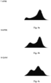
- FIG. 4a thus illustrates the shape of the histograms of the numbers of occurrences of amplitude values of signals modulated according to a 7APSK modulation (7-symbol amplitude and phase modulation);
- Figure 4b illustrates the shape of the histograms of the numbers of occurrences of amplitude values of signals modulated according to a 16APSK modulation (16-symbol amplitude and phase modulation);
- the figure 4c illustrates the shape of the histograms of the numbers of occurrences of amplitude values of signals modulated according to a 16QAM modulation (16-symbol quadrature amplitude modulation).
- the probability density D Se (Pi) of the average power of the variable envelope input signal Se to be amplified is used as a function of each instantaneous power value Pi of this variable envelope input signal Se to be amplified to calculate, during step 14, the mathematical expectation of at least one optimization parameter linked to the average power of the amplified output signal, from at least said ideal variation in average power POUT L (PIN).
- at least one such optimization parameter is chosen from the average output power POUTk of the amplifier and the consumption PDCk of the amplifier.
- each optimization parameter depends on the optimization criterion of the amplifier that we want to retain, which itself depends on the application of the amplification stage to be manufactured.
- these formulas are implemented by applying statistical formulas to the tables of values giving D Se ( Pi ) and POUT L ( Pi ) using a spreadsheet.
- a calculation can be carried out that is at least partly analytical, from an analytical function (or an analytical approximation) of the probability density D Se ( Pi ) and an analytical approximation, for example polynomial, of P OUT L ( Pi ).
- E DISS L Pi E PDC L Pi ⁇ E POUT L Pi
- each mathematical expectation is calculated from the ideal variation of the corresponding optimization parameter, that is to say at least from the ideal variation in mean power POUT L (PIN).
- PIN mean power
- an amplifier 32 corrected by adaptation circuits 33, 34 and 35 one can in fact use such an ideal variation to calculate each mathematical expectation used to calculate an optimization criterion, while guaranteeing that the amplifier will satisfy predetermined performance criteria linked to the previously made choice of this ideal variation.
- a linearized ideal variation as indicated above, one can guarantee that the amplifier will provide a predetermined signal-to-noise ratio or intermodulation rate for any value of its average output power.
- step 14 the different calculations of the optimization criterion carried out for each value of each adjustment parameter Vd, Vg, Z, ⁇ are recorded in a table.
- an optimal combination of the values of the adjustment parameters Vd, Vg, Z, ⁇ is determined from the table of calculated values of the optimization criterion, to optimize this optimization criterion of the amplifier.
- the optimal combination is determined in the table which provides the largest numerical value ⁇ max of the efficiency ⁇ ; or the one which provides the largest numerical value Max[POUTk] of the average output power POUTk; or the one which provides the lowest numerical value Min[PDCk] of the consumption PDCk.
- control parameters of an amplifier can be determined in accordance with the method according to the invention not only for amplifiers formed from field effect transistors (solid state circuits), but also for traveling wave tubes, the control parameters then typically being the beam current Ik dictated by the voltage VA 0 , the helix voltage Vh and the voltages of collectors Vc1,2,3,4. Steps 11 to 15 can indeed be implemented with these adjustment parameters.
- the value of the average output power POUTk E POUT L [ Pi ] of the amplifier corresponding to this optimal combination, and the number N of amplifier(s) A1, A2,...Ak,..., AN, to be used in the amplification stage is determined in step 16 such that the average output power POUT of the amplification stage can be obtained by paralleling several amplifiers A1, A2,...Ak,..., AN, as shown figure 5 , if necessary.
- the number N of amplifiers A1, A2,...Ak,..., AN in parallel is determined such that: ⁇ 1 N ⁇ 1 POUTk ⁇ POUT ⁇ ⁇ 1 N POUTk
- the average power of the input signal is not a given constraint, but is determined to correspond to the optimal combination of the adjustment parameters of each amplifier and the corresponding average output power POUTk.
- the amplification stage comprises for each amplifier 32, an upstream linearization circuit 33 (making it possible in particular to obtain an ideal variation in the average output power of the amplifier), a load impedance 34 at the output and a biasing device 35 providing the bias voltages Vg, Vd of the transistor 32.
- the linearization circuit 33, the load impedance 34 at the output and the biasing device 35 are adaptation circuits of the amplification stage.
- These adaptation circuits 33, 34, 35 have fixed characteristics corresponding to the optimal values of the adjustment parameters and which do not depend in particular dynamically on the characteristics of the input signal.
- the amplification stage comprises a plurality of such identical amplifiers 32, it is possible to use a single linearization circuit 33 common to the different amplifiers 32, a single output circuit constituting the load impedance 34 for all the amplifiers 32, and a single bias circuit 35 providing the different bias voltages to the different transistors in parallel.
Landscapes
- Engineering & Computer Science (AREA)
- Power Engineering (AREA)
- Physics & Mathematics (AREA)
- Nonlinear Science (AREA)
- Amplifiers (AREA)
- Microwave Amplifiers (AREA)
Applications Claiming Priority (2)
| Application Number | Priority Date | Filing Date | Title |
|---|---|---|---|
| FR1560585A FR3043286B1 (fr) | 2015-11-04 | 2015-11-04 | Procede de fabrication d'un etage d'amplification d'un signal a enveloppe variable |
| PCT/EP2016/076552 WO2017076969A1 (fr) | 2015-11-04 | 2016-11-03 | Procédé de fabrication d'un étage d'amplification d'un signal à enveloppe variable |
Publications (3)
| Publication Number | Publication Date |
|---|---|
| EP3371884A1 EP3371884A1 (fr) | 2018-09-12 |
| EP3371884B1 true EP3371884B1 (fr) | 2024-08-28 |
| EP3371884C0 EP3371884C0 (fr) | 2024-08-28 |
Family
ID=56101497
Family Applications (1)
| Application Number | Title | Priority Date | Filing Date |
|---|---|---|---|
| EP16790381.4A Active EP3371884B1 (fr) | 2015-11-04 | 2016-11-03 | Procédé de fabrication d'un étage d'amplification d'un signal à enveloppe variable et étage d'amplification de puissance |
Country Status (5)
| Country | Link |
|---|---|
| US (1) | US10826444B2 (enExample) |
| EP (1) | EP3371884B1 (enExample) |
| JP (1) | JP6872542B2 (enExample) |
| FR (1) | FR3043286B1 (enExample) |
| WO (1) | WO2017076969A1 (enExample) |
Families Citing this family (3)
| Publication number | Priority date | Publication date | Assignee | Title |
|---|---|---|---|---|
| US10985951B2 (en) | 2019-03-15 | 2021-04-20 | The Research Foundation for the State University | Integrating Volterra series model and deep neural networks to equalize nonlinear power amplifiers |
| US12381522B2 (en) | 2021-03-09 | 2025-08-05 | Skyworks Solutions, Inc. | Average power tracking systems with fast transient settling |
| CN116743095B (zh) * | 2023-03-10 | 2024-06-25 | 振弦(苏州)微电子有限公司 | 一种改善各功率管输出功率一致性的pa及设计方法 |
Citations (1)
| Publication number | Priority date | Publication date | Assignee | Title |
|---|---|---|---|---|
| EP2840709A1 (en) * | 2013-08-22 | 2015-02-25 | Telefonaktiebolaget L M Ericsson (publ) | Amplifier and method of amplification |
Family Cites Families (9)
| Publication number | Priority date | Publication date | Assignee | Title |
|---|---|---|---|---|
| FR1453773A (fr) | 1965-11-16 | 1966-06-03 | Heberlein & Co Ag | Montage photoélectrique, notamment pour épurateurs électroniques de fils |
| US6141541A (en) * | 1997-12-31 | 2000-10-31 | Motorola, Inc. | Method, device, phone and base station for providing envelope-following for variable envelope radio frequency signals |
| FI106412B (fi) * | 1998-11-10 | 2001-01-31 | Nokia Mobile Phones Ltd | Lineaarinen tehovahvistinjärjestely ja menetelmä sen käyttämiseksi |
| JP2001094350A (ja) * | 1999-08-31 | 2001-04-06 | Samsung Electronics Co Ltd | 携帯電話端末用電力増幅器 |
| GB2427772B (en) * | 2002-09-26 | 2007-04-11 | Qualcomm Inc | A transmitter |
| GB2438457B (en) * | 2006-03-17 | 2011-09-14 | Nujira Ltd | Joint optimisation of supply and bias modulation |
| US8185066B2 (en) * | 2009-10-23 | 2012-05-22 | Sony Mobile Communications Ab | Multimode power amplifier with predistortion |
| GB2500708B (en) * | 2012-03-30 | 2016-04-13 | Nujira Ltd | Determination of envelope shaping and signal path predistortion of an ET amplification stage using device characterisation data |
| US9520907B2 (en) * | 2014-02-16 | 2016-12-13 | Mediatek Inc. | Methods and apparatus for envelope tracking system |
-
2015
- 2015-11-04 FR FR1560585A patent/FR3043286B1/fr active Active
-
2016
- 2016-11-03 US US15/773,051 patent/US10826444B2/en active Active
- 2016-11-03 JP JP2018522515A patent/JP6872542B2/ja active Active
- 2016-11-03 EP EP16790381.4A patent/EP3371884B1/fr active Active
- 2016-11-03 WO PCT/EP2016/076552 patent/WO2017076969A1/fr not_active Ceased
Patent Citations (1)
| Publication number | Priority date | Publication date | Assignee | Title |
|---|---|---|---|---|
| EP2840709A1 (en) * | 2013-08-22 | 2015-02-25 | Telefonaktiebolaget L M Ericsson (publ) | Amplifier and method of amplification |
Also Published As
| Publication number | Publication date |
|---|---|
| EP3371884A1 (fr) | 2018-09-12 |
| FR3043286B1 (fr) | 2018-08-10 |
| JP2018536349A (ja) | 2018-12-06 |
| JP6872542B2 (ja) | 2021-05-19 |
| EP3371884C0 (fr) | 2024-08-28 |
| FR3043286A1 (fr) | 2017-05-05 |
| US20180316320A1 (en) | 2018-11-01 |
| US10826444B2 (en) | 2020-11-03 |
| WO2017076969A1 (fr) | 2017-05-11 |
Similar Documents
| Publication | Publication Date | Title |
|---|---|---|
| EP1986333B1 (fr) | Linéarisation dans une chaîne d'émission | |
| FR2798244A1 (fr) | Circuit et procede d'amplification de puissance a rendement eleve autorisant une large gamme de reduction de puissance dynamique | |
| FR2837647A1 (fr) | Emetteur sans fil a consommation de puissance reduite | |
| FR2773423A1 (fr) | Procede et systeme de linearisation numerique d'un amplificateur | |
| FR2835120A1 (fr) | Procede et dispositif de preparation de signaux destines a etre compares pour etablir une pre-distorsion sur l'entree d'un amplificateur | |
| EP3371884B1 (fr) | Procédé de fabrication d'un étage d'amplification d'un signal à enveloppe variable et étage d'amplification de puissance | |
| WO2019207476A1 (fr) | Systeme et procede de linearisation en bande de base pour un amplificateur de puissance radiofrequence de classe g | |
| EP2670048A1 (fr) | Procédé de calibration de linéariseur et composant électronique linéarisé | |
| FR3067891A1 (fr) | Linearisation d'une chaine de transmission de signaux radiofrequences | |
| FR3091796A1 (fr) | Circuit électronique de détection d’enveloppe et démodulateur correspondant | |
| CA2197236A1 (fr) | Dispositif de correction de la caracteristique amplitude/frequence d'un signal ayant transite par un cable et egaliseur frequentiel correspondant | |
| FR2904711A1 (fr) | Procede de compensation numerique de non linearites dans un systeme de communication et dispositif recepteur | |
| EP1311062B1 (fr) | Procédé d'optimisation du rendement d'un amplificateur destiné à amplifier simultanement plusieurs porteuses modulées | |
| EP2929459B1 (fr) | Procédé et dispositif d'évaluation prédictive de la puissance d'intermodulation dans un dispositif électronique | |
| EP2504963B1 (fr) | Systeme et procede d'emission reception d'un signal numerique sur voie radio | |
| EP3503385B1 (fr) | Synchronisation temporelle à faible complexité dans une boucle de calcul de prédistorsion numérique | |
| EP2039000B1 (fr) | Dispositif d'amplification d'un signal hyperfrequence a large bande | |
| EP3182586B1 (fr) | Amplificateur de puissance rf a double transistors et poste rf utilisant un tel amplificateur | |
| EP4300821B1 (fr) | Dispositif de communication comprenant un amplificateur de puissance et procédé de mise en oeuvre | |
| EP3430779B1 (fr) | Procédé et dispositif de génération d'un signal multiporteuse de type ofdm, procédé et dispositif d'atténuation d'extrema d'un tel signal, produits programme d'ordinateur correspondants | |
| FR3020527A1 (fr) | Procede de configuration d'un circuit corrige comprenant un circuit imparfait et un circuit de pre-distorsion | |
| EP2529522B1 (fr) | Procede de reduction de longueur de canal, filtre et signal correspondants | |
| Dos Reis | New baseband architectures using machine learning and deep learning in the presence of nonlinearities and dynamic environment | |
| FR3058254A1 (fr) | Procede de mise en forme d'un signal en vue de son amplification, procede d'amplification, dispositif de mise en forme, et dispositif d'amplification associes | |
| EP1074092A1 (fr) | Procede de neutrodynage du tube d'un emetteur |
Legal Events
| Date | Code | Title | Description |
|---|---|---|---|
| STAA | Information on the status of an ep patent application or granted ep patent |
Free format text: STATUS: UNKNOWN |
|
| STAA | Information on the status of an ep patent application or granted ep patent |
Free format text: STATUS: THE INTERNATIONAL PUBLICATION HAS BEEN MADE |
|
| PUAI | Public reference made under article 153(3) epc to a published international application that has entered the european phase |
Free format text: ORIGINAL CODE: 0009012 |
|
| STAA | Information on the status of an ep patent application or granted ep patent |
Free format text: STATUS: REQUEST FOR EXAMINATION WAS MADE |
|
| 17P | Request for examination filed |
Effective date: 20180326 |
|
| AK | Designated contracting states |
Kind code of ref document: A1 Designated state(s): AL AT BE BG CH CY CZ DE DK EE ES FI FR GB GR HR HU IE IS IT LI LT LU LV MC MK MT NL NO PL PT RO RS SE SI SK SM TR |
|
| AX | Request for extension of the european patent |
Extension state: BA ME |
|
| DAV | Request for validation of the european patent (deleted) | ||
| DAX | Request for extension of the european patent (deleted) | ||
| STAA | Information on the status of an ep patent application or granted ep patent |
Free format text: STATUS: EXAMINATION IS IN PROGRESS |
|
| 17Q | First examination report despatched |
Effective date: 20210226 |
|
| GRAP | Despatch of communication of intention to grant a patent |
Free format text: ORIGINAL CODE: EPIDOSNIGR1 |
|
| STAA | Information on the status of an ep patent application or granted ep patent |
Free format text: STATUS: GRANT OF PATENT IS INTENDED |
|
| INTG | Intention to grant announced |
Effective date: 20240417 |
|
| GRAS | Grant fee paid |
Free format text: ORIGINAL CODE: EPIDOSNIGR3 |
|
| GRAA | (expected) grant |
Free format text: ORIGINAL CODE: 0009210 |
|
| STAA | Information on the status of an ep patent application or granted ep patent |
Free format text: STATUS: THE PATENT HAS BEEN GRANTED |
|
| AK | Designated contracting states |
Kind code of ref document: B1 Designated state(s): AL AT BE BG CH CY CZ DE DK EE ES FI FR GB GR HR HU IE IS IT LI LT LU LV MC MK MT NL NO PL PT RO RS SE SI SK SM TR |
|
| REG | Reference to a national code |
Ref country code: GB Ref legal event code: FG4D Free format text: NOT ENGLISH |
|
| REG | Reference to a national code |
Ref country code: CH Ref legal event code: EP |
|
| REG | Reference to a national code |
Ref country code: DE Ref legal event code: R096 Ref document number: 602016089133 Country of ref document: DE |
|
| REG | Reference to a national code |
Ref country code: IE Ref legal event code: FG4D Free format text: LANGUAGE OF EP DOCUMENT: FRENCH |
|
| U01 | Request for unitary effect filed |
Effective date: 20240917 |
|
| U07 | Unitary effect registered |
Designated state(s): AT BE BG DE DK EE FI FR IT LT LU LV MT NL PT RO SE SI Effective date: 20241010 |
|
| U20 | Renewal fee for the european patent with unitary effect paid |
Year of fee payment: 9 Effective date: 20241015 |
|
| PG25 | Lapsed in a contracting state [announced via postgrant information from national office to epo] |
Ref country code: NO Free format text: LAPSE BECAUSE OF FAILURE TO SUBMIT A TRANSLATION OF THE DESCRIPTION OR TO PAY THE FEE WITHIN THE PRESCRIBED TIME-LIMIT Effective date: 20241128 |
|
| PG25 | Lapsed in a contracting state [announced via postgrant information from national office to epo] |
Ref country code: PL Free format text: LAPSE BECAUSE OF FAILURE TO SUBMIT A TRANSLATION OF THE DESCRIPTION OR TO PAY THE FEE WITHIN THE PRESCRIBED TIME-LIMIT Effective date: 20240828 Ref country code: GR Free format text: LAPSE BECAUSE OF FAILURE TO SUBMIT A TRANSLATION OF THE DESCRIPTION OR TO PAY THE FEE WITHIN THE PRESCRIBED TIME-LIMIT Effective date: 20241129 |
|
| PG25 | Lapsed in a contracting state [announced via postgrant information from national office to epo] |
Ref country code: IS Free format text: LAPSE BECAUSE OF FAILURE TO SUBMIT A TRANSLATION OF THE DESCRIPTION OR TO PAY THE FEE WITHIN THE PRESCRIBED TIME-LIMIT Effective date: 20241228 |
|
| PG25 | Lapsed in a contracting state [announced via postgrant information from national office to epo] |
Ref country code: HR Free format text: LAPSE BECAUSE OF FAILURE TO SUBMIT A TRANSLATION OF THE DESCRIPTION OR TO PAY THE FEE WITHIN THE PRESCRIBED TIME-LIMIT Effective date: 20240828 |
|
| PG25 | Lapsed in a contracting state [announced via postgrant information from national office to epo] |
Ref country code: ES Free format text: LAPSE BECAUSE OF FAILURE TO SUBMIT A TRANSLATION OF THE DESCRIPTION OR TO PAY THE FEE WITHIN THE PRESCRIBED TIME-LIMIT Effective date: 20240828 Ref country code: RS Free format text: LAPSE BECAUSE OF FAILURE TO SUBMIT A TRANSLATION OF THE DESCRIPTION OR TO PAY THE FEE WITHIN THE PRESCRIBED TIME-LIMIT Effective date: 20241128 |
|
| PG25 | Lapsed in a contracting state [announced via postgrant information from national office to epo] |
Ref country code: RS Free format text: LAPSE BECAUSE OF FAILURE TO SUBMIT A TRANSLATION OF THE DESCRIPTION OR TO PAY THE FEE WITHIN THE PRESCRIBED TIME-LIMIT Effective date: 20241128 Ref country code: PL Free format text: LAPSE BECAUSE OF FAILURE TO SUBMIT A TRANSLATION OF THE DESCRIPTION OR TO PAY THE FEE WITHIN THE PRESCRIBED TIME-LIMIT Effective date: 20240828 Ref country code: NO Free format text: LAPSE BECAUSE OF FAILURE TO SUBMIT A TRANSLATION OF THE DESCRIPTION OR TO PAY THE FEE WITHIN THE PRESCRIBED TIME-LIMIT Effective date: 20241128 Ref country code: IS Free format text: LAPSE BECAUSE OF FAILURE TO SUBMIT A TRANSLATION OF THE DESCRIPTION OR TO PAY THE FEE WITHIN THE PRESCRIBED TIME-LIMIT Effective date: 20241228 Ref country code: HR Free format text: LAPSE BECAUSE OF FAILURE TO SUBMIT A TRANSLATION OF THE DESCRIPTION OR TO PAY THE FEE WITHIN THE PRESCRIBED TIME-LIMIT Effective date: 20240828 Ref country code: GR Free format text: LAPSE BECAUSE OF FAILURE TO SUBMIT A TRANSLATION OF THE DESCRIPTION OR TO PAY THE FEE WITHIN THE PRESCRIBED TIME-LIMIT Effective date: 20241129 Ref country code: ES Free format text: LAPSE BECAUSE OF FAILURE TO SUBMIT A TRANSLATION OF THE DESCRIPTION OR TO PAY THE FEE WITHIN THE PRESCRIBED TIME-LIMIT Effective date: 20240828 |
|
| PG25 | Lapsed in a contracting state [announced via postgrant information from national office to epo] |
Ref country code: SM Free format text: LAPSE BECAUSE OF FAILURE TO SUBMIT A TRANSLATION OF THE DESCRIPTION OR TO PAY THE FEE WITHIN THE PRESCRIBED TIME-LIMIT Effective date: 20240828 |
|
| PG25 | Lapsed in a contracting state [announced via postgrant information from national office to epo] |
Ref country code: CZ Free format text: LAPSE BECAUSE OF FAILURE TO SUBMIT A TRANSLATION OF THE DESCRIPTION OR TO PAY THE FEE WITHIN THE PRESCRIBED TIME-LIMIT Effective date: 20240828 |
|
| PG25 | Lapsed in a contracting state [announced via postgrant information from national office to epo] |
Ref country code: SK Free format text: LAPSE BECAUSE OF FAILURE TO SUBMIT A TRANSLATION OF THE DESCRIPTION OR TO PAY THE FEE WITHIN THE PRESCRIBED TIME-LIMIT Effective date: 20240828 |
|
| REG | Reference to a national code |
Ref country code: CH Ref legal event code: PL |
|
| PLBE | No opposition filed within time limit |
Free format text: ORIGINAL CODE: 0009261 |
|
| STAA | Information on the status of an ep patent application or granted ep patent |
Free format text: STATUS: NO OPPOSITION FILED WITHIN TIME LIMIT |
|
| PG25 | Lapsed in a contracting state [announced via postgrant information from national office to epo] |
Ref country code: MC Free format text: LAPSE BECAUSE OF FAILURE TO SUBMIT A TRANSLATION OF THE DESCRIPTION OR TO PAY THE FEE WITHIN THE PRESCRIBED TIME-LIMIT Effective date: 20240828 |
|
| REG | Reference to a national code |
Ref country code: CH Ref legal event code: PL |
|
| GBPC | Gb: european patent ceased through non-payment of renewal fee |
Effective date: 20241128 |
|
| PG25 | Lapsed in a contracting state [announced via postgrant information from national office to epo] |
Ref country code: CH Free format text: LAPSE BECAUSE OF NON-PAYMENT OF DUE FEES Effective date: 20241130 |
|
| 26N | No opposition filed |
Effective date: 20250530 |
|
| PG25 | Lapsed in a contracting state [announced via postgrant information from national office to epo] |
Ref country code: GB Free format text: LAPSE BECAUSE OF NON-PAYMENT OF DUE FEES Effective date: 20241128 |
|
| PG25 | Lapsed in a contracting state [announced via postgrant information from national office to epo] |
Ref country code: IE Free format text: LAPSE BECAUSE OF NON-PAYMENT OF DUE FEES Effective date: 20241103 |
|
| U20 | Renewal fee for the european patent with unitary effect paid |
Year of fee payment: 10 Effective date: 20251015 |