EP3371869B1 - Charging apparatus and charging network having such charging apparatuses - Google Patents
Charging apparatus and charging network having such charging apparatuses Download PDFInfo
- Publication number
- EP3371869B1 EP3371869B1 EP16784288.9A EP16784288A EP3371869B1 EP 3371869 B1 EP3371869 B1 EP 3371869B1 EP 16784288 A EP16784288 A EP 16784288A EP 3371869 B1 EP3371869 B1 EP 3371869B1
- Authority
- EP
- European Patent Office
- Prior art keywords
- charging
- housing
- adapter
- module
- charging module
- Prior art date
- Legal status (The legal status is an assumption and is not a legal conclusion. Google has not performed a legal analysis and makes no representation as to the accuracy of the status listed.)
- Active
Links
Images

Classifications
-
- H—ELECTRICITY
- H02—GENERATION; CONVERSION OR DISTRIBUTION OF ELECTRIC POWER
- H02J—CIRCUIT ARRANGEMENTS OR SYSTEMS FOR SUPPLYING OR DISTRIBUTING ELECTRIC POWER; SYSTEMS FOR STORING ELECTRIC ENERGY
- H02J7/00—Circuit arrangements for charging or depolarising batteries or for supplying loads from batteries
- H02J7/0042—Circuit arrangements for charging or depolarising batteries or for supplying loads from batteries characterised by the mechanical construction
-
- B—PERFORMING OPERATIONS; TRANSPORTING
- B60—VEHICLES IN GENERAL
- B60L—PROPULSION OF ELECTRICALLY-PROPELLED VEHICLES; SUPPLYING ELECTRIC POWER FOR AUXILIARY EQUIPMENT OF ELECTRICALLY-PROPELLED VEHICLES; ELECTRODYNAMIC BRAKE SYSTEMS FOR VEHICLES IN GENERAL; MAGNETIC SUSPENSION OR LEVITATION FOR VEHICLES; MONITORING OPERATING VARIABLES OF ELECTRICALLY-PROPELLED VEHICLES; ELECTRIC SAFETY DEVICES FOR ELECTRICALLY-PROPELLED VEHICLES
- B60L53/00—Methods of charging batteries, specially adapted for electric vehicles; Charging stations or on-board charging equipment therefor; Exchange of energy storage elements in electric vehicles
- B60L53/10—Methods of charging batteries, specially adapted for electric vehicles; Charging stations or on-board charging equipment therefor; Exchange of energy storage elements in electric vehicles characterised by the energy transfer between the charging station and the vehicle
- B60L53/14—Conductive energy transfer
- B60L53/16—Connectors, e.g. plugs or sockets, specially adapted for charging electric vehicles
-
- B—PERFORMING OPERATIONS; TRANSPORTING
- B60—VEHICLES IN GENERAL
- B60L—PROPULSION OF ELECTRICALLY-PROPELLED VEHICLES; SUPPLYING ELECTRIC POWER FOR AUXILIARY EQUIPMENT OF ELECTRICALLY-PROPELLED VEHICLES; ELECTRODYNAMIC BRAKE SYSTEMS FOR VEHICLES IN GENERAL; MAGNETIC SUSPENSION OR LEVITATION FOR VEHICLES; MONITORING OPERATING VARIABLES OF ELECTRICALLY-PROPELLED VEHICLES; ELECTRIC SAFETY DEVICES FOR ELECTRICALLY-PROPELLED VEHICLES
- B60L53/00—Methods of charging batteries, specially adapted for electric vehicles; Charging stations or on-board charging equipment therefor; Exchange of energy storage elements in electric vehicles
- B60L53/30—Constructional details of charging stations
- B60L53/31—Charging columns specially adapted for electric vehicles
-
- B—PERFORMING OPERATIONS; TRANSPORTING
- B60—VEHICLES IN GENERAL
- B60L—PROPULSION OF ELECTRICALLY-PROPELLED VEHICLES; SUPPLYING ELECTRIC POWER FOR AUXILIARY EQUIPMENT OF ELECTRICALLY-PROPELLED VEHICLES; ELECTRODYNAMIC BRAKE SYSTEMS FOR VEHICLES IN GENERAL; MAGNETIC SUSPENSION OR LEVITATION FOR VEHICLES; MONITORING OPERATING VARIABLES OF ELECTRICALLY-PROPELLED VEHICLES; ELECTRIC SAFETY DEVICES FOR ELECTRICALLY-PROPELLED VEHICLES
- B60L53/00—Methods of charging batteries, specially adapted for electric vehicles; Charging stations or on-board charging equipment therefor; Exchange of energy storage elements in electric vehicles
- B60L53/60—Monitoring or controlling charging stations
- B60L53/66—Data transfer between charging stations and vehicles
-
- G—PHYSICS
- G06—COMPUTING; CALCULATING OR COUNTING
- G06K—GRAPHICAL DATA READING; PRESENTATION OF DATA; RECORD CARRIERS; HANDLING RECORD CARRIERS
- G06K7/00—Methods or arrangements for sensing record carriers, e.g. for reading patterns
- G06K7/10—Methods or arrangements for sensing record carriers, e.g. for reading patterns by electromagnetic radiation, e.g. optical sensing; by corpuscular radiation
- G06K7/10009—Methods or arrangements for sensing record carriers, e.g. for reading patterns by electromagnetic radiation, e.g. optical sensing; by corpuscular radiation sensing by radiation using wavelengths larger than 0.1 mm, e.g. radio-waves or microwaves
- G06K7/10366—Methods or arrangements for sensing record carriers, e.g. for reading patterns by electromagnetic radiation, e.g. optical sensing; by corpuscular radiation sensing by radiation using wavelengths larger than 0.1 mm, e.g. radio-waves or microwaves the interrogation device being adapted for miscellaneous applications
-
- G—PHYSICS
- G06—COMPUTING; CALCULATING OR COUNTING
- G06Q—INFORMATION AND COMMUNICATION TECHNOLOGY [ICT] SPECIALLY ADAPTED FOR ADMINISTRATIVE, COMMERCIAL, FINANCIAL, MANAGERIAL OR SUPERVISORY PURPOSES; SYSTEMS OR METHODS SPECIALLY ADAPTED FOR ADMINISTRATIVE, COMMERCIAL, FINANCIAL, MANAGERIAL OR SUPERVISORY PURPOSES, NOT OTHERWISE PROVIDED FOR
- G06Q20/00—Payment architectures, schemes or protocols
- G06Q20/38—Payment protocols; Details thereof
- G06Q20/40—Authorisation, e.g. identification of payer or payee, verification of customer or shop credentials; Review and approval of payers, e.g. check credit lines or negative lists
- G06Q20/401—Transaction verification
- G06Q20/4014—Identity check for transactions
-
- H—ELECTRICITY
- H02—GENERATION; CONVERSION OR DISTRIBUTION OF ELECTRIC POWER
- H02J—CIRCUIT ARRANGEMENTS OR SYSTEMS FOR SUPPLYING OR DISTRIBUTING ELECTRIC POWER; SYSTEMS FOR STORING ELECTRIC ENERGY
- H02J7/00—Circuit arrangements for charging or depolarising batteries or for supplying loads from batteries
- H02J7/0013—Circuit arrangements for charging or depolarising batteries or for supplying loads from batteries acting upon several batteries simultaneously or sequentially
-
- H—ELECTRICITY
- H02—GENERATION; CONVERSION OR DISTRIBUTION OF ELECTRIC POWER
- H02J—CIRCUIT ARRANGEMENTS OR SYSTEMS FOR SUPPLYING OR DISTRIBUTING ELECTRIC POWER; SYSTEMS FOR STORING ELECTRIC ENERGY
- H02J2310/00—The network for supplying or distributing electric power characterised by its spatial reach or by the load
- H02J2310/10—The network having a local or delimited stationary reach
- H02J2310/20—The network being internal to a load
- H02J2310/22—The load being a portable electronic device
-
- H—ELECTRICITY
- H02—GENERATION; CONVERSION OR DISTRIBUTION OF ELECTRIC POWER
- H02J—CIRCUIT ARRANGEMENTS OR SYSTEMS FOR SUPPLYING OR DISTRIBUTING ELECTRIC POWER; SYSTEMS FOR STORING ELECTRIC ENERGY
- H02J2310/00—The network for supplying or distributing electric power characterised by its spatial reach or by the load
- H02J2310/40—The network being an on-board power network, i.e. within a vehicle
- H02J2310/48—The network being an on-board power network, i.e. within a vehicle for electric vehicles [EV] or hybrid vehicles [HEV]
-
- Y—GENERAL TAGGING OF NEW TECHNOLOGICAL DEVELOPMENTS; GENERAL TAGGING OF CROSS-SECTIONAL TECHNOLOGIES SPANNING OVER SEVERAL SECTIONS OF THE IPC; TECHNICAL SUBJECTS COVERED BY FORMER USPC CROSS-REFERENCE ART COLLECTIONS [XRACs] AND DIGESTS
- Y02—TECHNOLOGIES OR APPLICATIONS FOR MITIGATION OR ADAPTATION AGAINST CLIMATE CHANGE
- Y02T—CLIMATE CHANGE MITIGATION TECHNOLOGIES RELATED TO TRANSPORTATION
- Y02T10/00—Road transport of goods or passengers
- Y02T10/60—Other road transportation technologies with climate change mitigation effect
- Y02T10/70—Energy storage systems for electromobility, e.g. batteries
-
- Y—GENERAL TAGGING OF NEW TECHNOLOGICAL DEVELOPMENTS; GENERAL TAGGING OF CROSS-SECTIONAL TECHNOLOGIES SPANNING OVER SEVERAL SECTIONS OF THE IPC; TECHNICAL SUBJECTS COVERED BY FORMER USPC CROSS-REFERENCE ART COLLECTIONS [XRACs] AND DIGESTS
- Y02—TECHNOLOGIES OR APPLICATIONS FOR MITIGATION OR ADAPTATION AGAINST CLIMATE CHANGE
- Y02T—CLIMATE CHANGE MITIGATION TECHNOLOGIES RELATED TO TRANSPORTATION
- Y02T10/00—Road transport of goods or passengers
- Y02T10/60—Other road transportation technologies with climate change mitigation effect
- Y02T10/7072—Electromobility specific charging systems or methods for batteries, ultracapacitors, supercapacitors or double-layer capacitors
-
- Y—GENERAL TAGGING OF NEW TECHNOLOGICAL DEVELOPMENTS; GENERAL TAGGING OF CROSS-SECTIONAL TECHNOLOGIES SPANNING OVER SEVERAL SECTIONS OF THE IPC; TECHNICAL SUBJECTS COVERED BY FORMER USPC CROSS-REFERENCE ART COLLECTIONS [XRACs] AND DIGESTS
- Y02—TECHNOLOGIES OR APPLICATIONS FOR MITIGATION OR ADAPTATION AGAINST CLIMATE CHANGE
- Y02T—CLIMATE CHANGE MITIGATION TECHNOLOGIES RELATED TO TRANSPORTATION
- Y02T90/00—Enabling technologies or technologies with a potential or indirect contribution to GHG emissions mitigation
- Y02T90/10—Technologies relating to charging of electric vehicles
- Y02T90/12—Electric charging stations
-
- Y—GENERAL TAGGING OF NEW TECHNOLOGICAL DEVELOPMENTS; GENERAL TAGGING OF CROSS-SECTIONAL TECHNOLOGIES SPANNING OVER SEVERAL SECTIONS OF THE IPC; TECHNICAL SUBJECTS COVERED BY FORMER USPC CROSS-REFERENCE ART COLLECTIONS [XRACs] AND DIGESTS
- Y02—TECHNOLOGIES OR APPLICATIONS FOR MITIGATION OR ADAPTATION AGAINST CLIMATE CHANGE
- Y02T—CLIMATE CHANGE MITIGATION TECHNOLOGIES RELATED TO TRANSPORTATION
- Y02T90/00—Enabling technologies or technologies with a potential or indirect contribution to GHG emissions mitigation
- Y02T90/10—Technologies relating to charging of electric vehicles
- Y02T90/14—Plug-in electric vehicles
-
- Y—GENERAL TAGGING OF NEW TECHNOLOGICAL DEVELOPMENTS; GENERAL TAGGING OF CROSS-SECTIONAL TECHNOLOGIES SPANNING OVER SEVERAL SECTIONS OF THE IPC; TECHNICAL SUBJECTS COVERED BY FORMER USPC CROSS-REFERENCE ART COLLECTIONS [XRACs] AND DIGESTS
- Y02—TECHNOLOGIES OR APPLICATIONS FOR MITIGATION OR ADAPTATION AGAINST CLIMATE CHANGE
- Y02T—CLIMATE CHANGE MITIGATION TECHNOLOGIES RELATED TO TRANSPORTATION
- Y02T90/00—Enabling technologies or technologies with a potential or indirect contribution to GHG emissions mitigation
- Y02T90/10—Technologies relating to charging of electric vehicles
- Y02T90/16—Information or communication technologies improving the operation of electric vehicles
- Y02T90/167—Systems integrating technologies related to power network operation and communication or information technologies for supporting the interoperability of electric or hybrid vehicles, i.e. smartgrids as interface for battery charging of electric vehicles [EV] or hybrid vehicles [HEV]
-
- Y—GENERAL TAGGING OF NEW TECHNOLOGICAL DEVELOPMENTS; GENERAL TAGGING OF CROSS-SECTIONAL TECHNOLOGIES SPANNING OVER SEVERAL SECTIONS OF THE IPC; TECHNICAL SUBJECTS COVERED BY FORMER USPC CROSS-REFERENCE ART COLLECTIONS [XRACs] AND DIGESTS
- Y04—INFORMATION OR COMMUNICATION TECHNOLOGIES HAVING AN IMPACT ON OTHER TECHNOLOGY AREAS
- Y04S—SYSTEMS INTEGRATING TECHNOLOGIES RELATED TO POWER NETWORK OPERATION, COMMUNICATION OR INFORMATION TECHNOLOGIES FOR IMPROVING THE ELECTRICAL POWER GENERATION, TRANSMISSION, DISTRIBUTION, MANAGEMENT OR USAGE, i.e. SMART GRIDS
- Y04S30/00—Systems supporting specific end-user applications in the sector of transportation
- Y04S30/10—Systems supporting the interoperability of electric or hybrid vehicles
- Y04S30/14—Details associated with the interoperability, e.g. vehicle recognition, authentication, identification or billing
Definitions
- the present disclosure relates generally to a charging apparatus; and more specifically, to a charging apparatus operable to provide different charging outputs.
- battery-powered devices The proliferation of battery-powered devices continues to expand as technology increases.
- One such example includes use of batteries in electric vehicles, such as electrical cars, bikes, cycles, segways and the like.
- batteries are rechargeable in nature and need to be recharged based on the usage thereof.
- charging stations may be used for charging such batteries of the electric vehicles.
- the charging stations are generally open spaces having number of charging units (or charging stands) installed therein. Therefore, the job of setting up a charging station is very expensive and time consuming task.
- charging apparatuses which can be mounted on electrical structures, such as lamp post, are known in the art. Specifically, such charging apparatuses are electrically coupled to a power supply cable (carried by the lamp post) to provide the required electrical charging power.
- the modular charging station system includes a base unit, a master module, and a user module.
- the base unit is configured without electronics and has at least one clamping device for the power feed and compartments for accommodating the master module and the user module.
- the master module and the user module form a high-current transmission device, with the master module having a socket and the user module having a plug that corresponds to the socket of the master module.
- such charging apparatuses may be associated with specific charging outputs, for example 16 Ampere (A), 32A, 63A or 120A. Therefore, once such charging apparatuses are mounted or installed on the electrical structures, such electrical structures (or charging point) are configured to provide charging outputs corresponding to the charging apparatuses installed thereon. For example, a charging apparatus installed in a particular lamp post may provide 32A of charging output, similarly another charging apparatus installed in another lamp post may provide 63A of charging output. Therefore, it may not be possible to obtain different charging outputs from a same charging point (particularly, from the same electrical structure or the same charging apparatus). Accordingly, to obtain increased or decreased charging output re-installation of the whole charging apparatus needs to be performed on the electrical structure, which is again an expensive and a time-consuming task.
- specific charging outputs for example 16 Ampere (A), 32A, 63A or 120A. Therefore, once such charging apparatuses are mounted or installed on the electrical structures, such electrical structures (or charging point) are configured to provide charging outputs corresponding to the charging apparatus
- an electric vehicle recharge station including a housing with an outlet switchably coupled to an electrical electric power source.
- a vehicle connectible plug is removably mounted on the housing and connected to the outlet for supplying electric power from the outlet to the vehicle.
- the housing is mountable on top of a concrete pedestal embedded in the ground.
- the vehicle connectible plug is connected to the outlet by a coiled electrical cord.
- the housing supports two outlets and two plugs.
- a user interface communicates and receives instructions to and from the user via a touch screen display. The user interface provides selection of power charge time periods, stations on the housing, and payment.
- the housing can be configured for home use via a wall mount or as a wall mount for a parking garage.
- the battery charger housing arrangement includes a battery charger configured to provide power to charge a vehicle battery, a reinforcement structure to hold the battery charger, and a housing configured to cover the reinforcement structure and the battery charger.
- the housing forms a waterproof covering to protect the battery charger from the environment, a charge cable extends from the housing and is configured to connect to and charge a vehicle, and a window is arranged in the housing so that a user may operate the battery charger.
- the reinforcement structure is configured to structurally locate the housing in a stable non-movable location.
- the charging station includes a housing, a first mounting member having a first coupling portion and a first locking portion, including a first locking aperture and a second mounting member having a second coupling portion coupleable to the first coupling portion to prevent a movement of the housing in one of a first and a second direction.
- the second mounting member includes a second locking portion with a latch surface.
- One of the mounting members is coupleable to the housing, and the other mounting member is coupleable to the mounting surface.
- a lock member is disposed in the first locking aperture, movable between a first disengaged position and a second engaged position. The lock member cooperates with the latch surface in the second engaged position, to prevent a movement of the housing in a third direction.
- a Charging station for charging an electrical load.
- the loading station comprises a housing adapted for closing an access opening to an interior of a device with power supply and the charging station to a power supply can be connected to the device. Moreover, the loading station via cable on electricity meter with the power supply of the device is connected and the electric consumer via the plug-in connection element to the charging station is connected.
- the present disclosure seeks to provide a charging apparatus.
- the present disclosure further seeks to provide a charging network.
- an embodiment of the present disclosure provides a charging apparatus comprising:
- an embodiment of the present disclosure provides a charging network comprising:
- Embodiments of the present disclosure substantially eliminate or at least partially address the aforementioned problems in the prior art, and enables in providing a charging apparatus operable to provide different charging outputs.
- an underlined number is employed to represent an item over which the underlined number is positioned or an item to which the underlined number is adjacent.
- a non-underlined number relates to an item identified by a line linking the non-underlined number to the item. When a number is non-underlined and accompanied by an associated arrow, the non-underlined number is used to identify a general item at which the arrow is pointing.
- an embodiment of the present disclosure provides a charging apparatus comprising:
- an embodiment of the present disclosure provides a charging network comprising:
- the present disclosure provides a charging apparatus which may be operable to provide different charging outputs.
- the term "charging output” used herein may be associated with amperage that may be provided by the charging apparatus.
- the charging apparatus may be operable to provide different charging outputs, such as 16 A, 32A, 63A and 120A, for charging different charging devices requiring different charging outputs.
- the charging devices relate to any type of device that is movable and could be powered by a power supply network.
- the charging devices may include electrical vehicle, such as electrical buses, cars, bikes, cycles, segways and the like.
- the charging device may be a car equipped with an electrically powered engine, preheater or car heater.
- the charging devices may include portable electronic gadgets.
- the charging devices may include mobile phones, laptops and the like.
- the charging apparatus of the present disclosure is configured to use a power supply cable for charging the charging devices.
- the power supply cable may be associated with a power station.
- the power supply cable may be associated with cables originating from a transformer station connected to the power station (with transmission cables).
- the power supply cable originates from the transformer station for distributing power to various power consuming sources, such as residential and commercial building, steers, airport, dock, railway station and the like.
- splitter boxes may be used in between the transformer station and the power consuming sources for power distribution and regulation (based on need and availability).
- the power supply cable may include a cross-section of about 25 mm 2 . Further, the power supply cable may carry current of 120 A or more.
- the charging apparatus may be operable to be used in conjunction with electrical structures, of a power consuming source, carrying the power supply cable.
- the charging apparatus may be mounted on such electrical structures (carrying the power supply cable) for getting access to the power supply cable.
- the electrical structures may include a lamp post or a street electrical enclosure carrying the power supply cable.
- the adapter of the charging apparatus is configured to receive the power supply cable.
- the adapter comprises a housing and a duct configured on the housing for receiving the power supply cable therethrough.
- the housing may be configured to have a cuboidal structure.
- the housing may be configured to have a cylindrical structure.
- the housing may be a rectangular box like structure having top and bottom walls, front and rear walls and side walls.
- the front wall of the housing may be detachable, whereas the remaining walls may be integral to form a single structure.
- the duct of the adapter may be configured on the bottom wall of the housing.
- the duct may be configured by a hollow cylindrical structure having an opening for receiving the power supply cable therethrough.
- the hollow cylindrical structure may be a bolt or a bush arranged on the bottom wall of the housing.
- the adapter further includes a connector coupled to the power supply cable.
- the adapter comprises a first connector adapted to be connected to the power supply cable and a second connector adapted to be connected (engaged electrically) with a charging module of the charging apparatus, which is explained in greater detail herein later.
- the first connector may be arranged inside the housing and connected to an end of the power supply cable
- the second connector may be arranged on (or extending from) the top wall of the housing and electrically coupled to the first connector.
- the front wall of the housing may be detachable. This allows the power supply cable to be suitably connected to the first and second connectors.
- the apparatus further comprises a plurality of locking tabs arranged on the housing.
- the locking tabs are arranged on both side walls of the housing.
- the locking tabs may be bolts (or similar structure) extending from the both side walls of the housing.
- each side wall may be carrying multiple locking tabs, such as 2 or 3 or 5 locking tabs.
- the rear wall of the housing includes a plurality of mounting holes configured thereon.
- the each of the plurality of mounting holes may enable in mounting the housing of the adapter to the electrical structures, such as the lamp post or the street electrical enclosure carrying the power supply cable.
- the mounting holes may be configured to receive tying means, such as wires, ropes and brackets, therethrough for mounting the housing onto the electrical structures.
- the rear wall of the housing may be configured to have a shape, such as concave or flat, such that the rear wall of the housing conforms to a shape of the electrical structures for being suitably mounted thereon.
- the rear wall of the housing may be configured to have a concave shape such that the housing may be suitably mounted on cylindrical lamp post.
- the adapter may also include a closable lid arranged on the housing of the adapter.
- the closable lid may be arranged on the top wall of the housing, such that the closable lid can cover the connector (particularly, the second connector) arranged on the top wall.
- the closable lid may be used for covering and protecting the connector of the adapter when only adapter is mounted on an electrical structure (without a charging module).
- the charging apparatus comprises at least one charging module associated with a specific charging output.
- the term "charging output” used herein may be associated with amperage of the charging module. Therefore, one or more charging modules constituting the at least one charging module of the charging apparatus may include various charging output. In an example, the one or more charging modules may include charging output, such as 16A, 32A, 63A, 120A and the like.
- the one of the at least one charging module is operatively and detachably coupled to the adapter.
- one charging module at a time is adapted to be operatively and detachably coupled to the adapter.
- that charging module may be associated with a charging output, such as 16A, 32A, 63A, 120A and the like.
- the each of the at least one charging module comprises a plug contact configured to be engaged with the connector of the adapter.
- the plug contact of the charging module may configured to be a male connector construction
- the connector of the adapter may configured to be a female connector construction to operatively engage with the plug contact.
- the plug contact is a toothed unit that enable the plug contact to get engaged into small openings of the connector.
- the each of the at least one charging module comprises a plurality of recesses for receiving the plurality of locking tabs for detachably coupling the one of the at least one charging module with the adapter.
- the housing of the adapter is detachably coupled to the charging module.
- the charging module comprises a cavity adapted to be at least partially receive the housing of the adapter therein. Further, on two sides of that cavity two planer structures are arranged. Each of the two planer structures comprises the recesses for receiving the plurality of locking tabs. Therefore, the housing of the adapter is received in the cavity of the charging module, such that initially the plug contact of the charging module engages with the connector of the adapter. Thereafter, the locking tabs may be received by the recesses.
- the recesses are configured to have L-shape and correspond to the number of the locking tabs. The recesses and locking tabs arrangement provides the detachable mechanical coupling between the charging module and the adapter.
- the each of the at least one charging module comprises a plug holder.
- the plug holder may be configured to be engaged to a cord and plug assembly of a charging device for being charged with a charging output corresponding to the one of at least one charging module.
- the plug holder may include different structural configurations corresponding to the charging outputs thereof. Accordingly, different charging devices (such as different electrical vehicles) may include different cord and plug assemblies corresponding to required different charging outputs.
- the adapter of the present disclosure may be configured to be replacably coupled to other charging modules of the at least one charging module having different charging outputs. This allows the same adapter to be operable in conjunction with charging modules of different charging outputs. This in turn provides a flexibility to simply change the charging module to yield different charging output rather replacing the entire charging apparatus for yielding different charging output.
- the charging apparatus of the present disclosure may be used for charging the portable electronic gadgets, such as mobile phones, laptops, music players and the like.
- the charging module may be configured to include one or more additional plug holder or electrical outlets electrically compatible for charging such electronic gadgets.
- the charging module may include slidable covers arranged on sides of the charging module. The slidable covers are configured to the cover the additional plug holder or electrical outlets for the portable electronic gadgets.
- the charging apparatus further comprises an identification tag carried by the each of the at least one charging module, and a tag reader carried by the adapter for reading the identification tag for identifying the charging output of the each of the at least one charging module.
- the identification tag is RFID (Radio Frequency Identification) and the tag reader is a RFID tag reader.
- tags like NFC (Near Field Communication) tag and tag readers like NFC tag reader can also be used.
- the RFID arrangement of the charging apparatus makes the charging apparatus an intelligent apparatus.
- the identification tag carries information for the adapter to how much power should be delivered i.e. the charging module. This allows a charging module having 32A charging output to receive 32A or less, and essentially not more than 32A. Further, if the tag reader fails to identify the information of the identification tag, then no power will be delivered from the adapter to the charging module.
- the charging module further comprises a controller.
- the controller may be operable to control power input from a power supply cable to the charging module.
- the charging module further comprises a communication module.
- the communication module may be configured to communicate data pertaining to the charging module in a communication network, such as communication networks GSM, 3G or 4G.
- the communication module may be configured to communicate with an intelligent unit or a cloud based central (described herein later), which may control the charging modules of the charging apparatuses present in the charging network.
- the power to the charging module may be controlled by the intelligent unit present in the charging network (or power distribution grid).
- the intelligent unit may include a processor, a memory means and a connection to the charging network (for example to the transformer station of the charging network).
- the memory means may be set up for storing rules for controlling a group of the charging modules.
- the processor may be set up for receiving data originating from a specific charging module of the group from the communication module and, in some embodiments forward this data to the cloud based central.
- the processor is then set up to process this data using input from rules stored in the memory means and, in some embodiments, from the cloud based central connected to the internet. Subsequently, the processor is set up to send instruction data to the charging modules.
- the cloud based central may be adapted to control the charging modules and/or the intelligent unit in the charging network (power distribution grid).
- the cloud based central may be a part of the charging network.
- the charging apparatus may be configured to manage a load in the charging network (power distribution grid). For example, when charging devices (such as electrical vehicles) are connected to respective charging apparatuses, in such instance the information regarding power consumption of the charging devices may be obtained by the intelligent unit (or may be provided to the cloud based central) to manage the load in the charging network. For example, the intelligent unit may instruct the transformer station of the charging network to regulate power in the charging network. For example, in case of overload, the power to the charging devices (i.e. to the charging apparatus) may be lowered.
- the intelligent unit may instruct the transformer station of the charging network to regulate power in the charging network. For example, in case of overload, the power to the charging devices (i.e. to the charging apparatus) may be lowered.
- the charging module may also include a payment section having means for obtaining payment from a user.
- the payment section is set up to send data relating to payment to the controller.
- the term "payment section” relates to a section for receiving payment data using the charging apparatus.
- this section is comprised of a credit card reader, optionally together with one or more input means. The user inserts his/her credit card in the reader and optionally enters a pin code. The payment section then forwards this data to the controller for proceeding with payment transactions.
- the charging module may also include identification means such as a Bluetooth reading means.
- identification means enables a user to be identified (i.e. user identification) by bringing an e-wallet (typically, a mobile phone comprising Bluetooth functionality) close to the reading means. This makes the user not to insert any credit card into the card reader of the payment section. In some embodiments, there may not be such payment section.
- the adapter may be provided with electromechanical locking hooks, which are adapted to engage with corresponding locking means on the charging module.
- a correct identification when the charging module has been connected to the adapter will generate a locking activity. Therefore, such locking hooks on the adapter and locking means on the charging module would make the charging apparatus of the present disclosure to be a tamper or theft-proof apparatus.
- the charging module may be provided with a display unit for displaying visual signals.
- the display unit may be typically some kind of light-emitting arrangement and/or screen for showing text messages.
- the display unit may provide information related to the charging module (such as its charging output, operating status and the like) and the user (such as user's identification, payment transaction and the like).
- the present disclosure provides a charging apparatus having two parts, a first part being an adapter and a second part being a charging module.
- the charging apparatus of the present disclosure is configured to be easily installed for allowing users to have access to charging power supply.
- the charging apparatus can be mounted on an existing electrical structure (such as, an existing electric pole) and thus eliminates a need for digging the ground for proving charging power supply.
- the charging apparatus of the present disclosure is operable to provide different charging outputs.
- the adapter of the charging apparatus may be configured to be operatively and detachably coupled to various charging modules having different charging outputs.
- a charging module having a charging output of 32A may be easily replaced with a charging module having a charging output of 63A.
- the adapter is a less expensive component, and thus it is cost efficient to set up the charging apparatus of the present disclosure which may be operable to provide different charging outputs.
- the adapter 100 comprises a housing 102.
- the housing 102 is a rectangular box like structure having a top wall 104, a bottom wall 106, a front wall 108, a rear wall 110 and side walls 112, 114.
- the adapter 100 further includes at least one connector adapted to be coupled to a power supply cable (shown in FIG. 2 ).
- the adapter 100 comprises a first connector (not shown) configured inside the housing 102 and a second connector 116 arranged on the top wall 104.
- the front wall 108 of the housing 102 may be detachable for allowing the power supply cable to be suitably connected to the first connector (not shown) and the second connector 116.
- the adapter 100 further comprises a plurality of locking tabs, such as the locking tabs 118, 120 and 122 arranged on the housing 102. As shown, the locking tabs 118, 120, 122 are arranged on the side wall 112 of the housing 102. Similarly, the side wall 114 of the housing 102 may include the locking tabs (not shown) arranged thereon. Further, the rear wall 110 of the housing 102 includes a plurality of mounting holes, such as mounting holes 124, 126, 128 and 130 configured thereon. The mounting holes 124, 126, 128, 130 are configured to receive tying means, such as wires, ropes and brackets (not shown) therethrough for mounting the housing 102 onto an electrical structure, such as a lamp post.
- tying means such as wires, ropes and brackets (not shown) therethrough for mounting the housing 102 onto an electrical structure, such as a lamp post.
- the adapter 100 also comprises a duct 200 configured on the bottom wall 106 of the housing 102.
- the duct 200 enables in receiving a power supply cable 202 therethrough.
- the duct 200 provides a water proof connection between the power supply cable 202 and the housing 102.
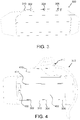
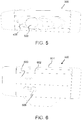
- FIGS. 3 to 6 illustrate perspective views of a charging module 300, in accordance with an embodiment of the present disclosure.
- the charging module 300 is associated with a specific charging output and is operatively and detachably coupled to the adapter 100.
- the adapter 100 of the FIGS. 1-2 and the charging module 300 of the FIGS. 3-6 together constitutes a charging apparatus of the present disclosure.
- the charging apparatus of the present disclosure includes at least one charging module (for example one or more charging module, such as charging module 300 ) adapted to be operatively and detachably coupled to the adapter 100.
- the adapter 100 is configured to be replacably coupled to other charging modules (of the one or more charging modules) having different charging outputs.
- the charging module 300 comprises a plurality of recesses, such as recesses 302, 304 and 306 for receiving the plurality of locking tabs 118, 120, 122 (shown in FIG. 1 and 2 ) for detachably coupling the charging module 300 with the adapter 100.
- the charging module 300 comprises two planer structures, such as a planer structure 310 (and other being not visible), having the recesses 302, 304, 306 configured thereon.
- the recesses 302, 304, 306 are configured to have L-shape, and correspond to the number of the locking tabs 118, 120, 122.
- the arrangement of the recesses 302, 304, 306 (on the charging module 300 ), and the locking tabs 118, 120 and 122 (on the adapter 100 ) provides the detachable mechanical coupling between the charging module 300 and the adapter 100.
- the adapter 100 is mounted on the electrical structure, such as the lamp post, other charging modules (having different charging outputs) may be replacably coupled to the adapter 100.
- the charging module 300 also comprises a plug contact 400 configured to be engaged with the connector 116 (particularly the second connector) of the adapter 100.
- the charging module 300 comprises a cavity 402 adapted to at least partially receive the housing 102 of the adapter 100 (shown in FIGS. 1-2 ).
- two planer structures 310 also shown in FIG. 3
- Each of the two planer structures 310, 404 comprises the recesses, such as the recesses 302, 304, 306, for receiving the plurality of locking tabs, such as the locking tabs 118, 120 and 122 (shown in FIG. 1-2 ) of the adapter 100.
- the housing 102 of the adapter 100 is received in the cavity 402 of the charging module 300, such that initially the plug contact 400 of the charging module 300 engages with the connector 116 of the adapter 100.
- the locking tabs 118, 120, 122 are received by the recesses 302, 304, 306, respectively, for enabling operative and detachable coupling between the adapter 100 and the charging module 300.
- the charging module 300 further comprises a plug holder 410.
- the plug holder 410 is configured to be engaged to a cord and plug assembly 412 of a charging device (such as, an electrical vehicle, not shown) for being charged with a charging output corresponding to the charging module 300.
- a charging device such as, an electrical vehicle, not shown
- the charging module 300 with the plug holder 408.
- the plug holder 408 comprises an opening 500 for receiving the cord and plug assembly 410 (shown in FIG. 4 ).
- the cavity 500 may be configured to have various configurations to accommodate various cord and plug assemblies (adapted to operate on various charging outputs) associated with various charging devices.
- the charging module 300 having a slidable cover 600 arranged on a side 602 of the charging module 300.
- the charging module 300 may also include another slidable cover arranged on other side 604 of the charging module 300.
- the slidable covers, such as the slidable cover 600 are configured to cover additional plug holders or electrical outlets, which may be suitable for being used in conjunction with portable electronic gadgets, such as laptop, mobile phones and the like.
- the charging module 300 also includes locking tabs, such as a locking tab 606, for slidably moving the slidable covers, such as the slidable cover 600.
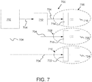
- the charging network 700 comprises a transformer station 702, a plurality of power supply cables, such as the power supply cables 704, originating from the transformer station 702.
- the charging network 700 also comprises a plurality of charging apparatus, such as charging apparatus 706, 708 and 710, electrically coupled to the plurality of power supply cables, such as the power supply cables 704.
- the power supply cables 704 are configured to connect the transformer station 702 directly to charging apparatuses, such as the charging apparatus 710. Otherwise, the power supply cables 704 may be configured to connect the transformer station 702 indirectly to charging apparatuses, such as the charging apparatuses 706, 708, or via a splitter box 712. Therefore, the power supply cables 704 enable in distributing power from the transformer station 702 to the charging apparatus 706, 708, 710. Further, the splitter box 712 also enables in distributing the power from the transformer station 702 to the charging apparatus 706, 708. In an embodiment, the splitter box 712 may also enable in regulating power (based on need and availability of power in the charging network 700 ).
- each of the charging apparatuses 706, 708 and 710 comprises an adapter and a charging module.
- the charging apparatus 706 comprises an adapter 714 and a charging module 716
- the charging apparatus 708 comprises an adapter 718 and a charging module 720
- the charging apparatus 710 comprises an adapter 722 and a charging module 724.
- the adapters 714, 718, 722 of the charging apparatuses 706, 708, 710 may be mounted on electrical structures, such as a lamp post (not shown).
- the charging modules 716, 720, 724 may be operatively and detachably coupled to the adapters 714, 718, 722, respectively.
- the charging modules 716, 720, 724 may be replacably coupled to the adapters 714, 718, 722. This enables the charging apparatuses 706, 708, 710 of the present disclosure to be operable to provide different charging outputs corresponding to the different charging modules 716, 720, 724.
Description
- The present disclosure relates generally to a charging apparatus; and more specifically, to a charging apparatus operable to provide different charging outputs.
- The proliferation of battery-powered devices continues to expand as technology increases. One such example includes use of batteries in electric vehicles, such as electrical cars, bikes, cycles, segways and the like. Generally, such batteries are rechargeable in nature and need to be recharged based on the usage thereof. Typically, charging stations may be used for charging such batteries of the electric vehicles.
- The charging stations are generally open spaces having number of charging units (or charging stands) installed therein. Therefore, the job of setting up a charging station is very expensive and time consuming task. To address such problem, the use of charging apparatuses, which can be mounted on electrical structures, such as lamp post, are known in the art. Specifically, such charging apparatuses are electrically coupled to a power supply cable (carried by the lamp post) to provide the required electrical charging power.
- In a United States patent application
US20110246014 , there is described a modular charging station system for conductive charging of the batteries of electric vehicles. The modular charging station system includes a base unit, a master module, and a user module. The base unit is configured without electronics and has at least one clamping device for the power feed and compartments for accommodating the master module and the user module. The master module and the user module form a high-current transmission device, with the master module having a socket and the user module having a plug that corresponds to the socket of the master module. - In another United States patent application
US20110140657 , there is described a method and system to deploy electrical charge spots in stages according to demand. During a first stage a plurality of infrastructure adapters are installed, which may involve demolishing and rebuilding portions of the infrastructure and laying down power cables from the electrical power supply to the charge spot locations. The infrastructure adapters are then coupled to an electrical power supply. Further, if not all, many of the infrastructure adapters are covered with a temporary housing protecting them from vandalism and weather. During a second stage, in response to a demand for charge stations, the charge stations are completed. During the second stage, at least one external unit is attached to an infrastructure adapter by making an infrastructure adapter quick connect interface with an external unit quick connect interface. - Typically, such charging apparatuses may be associated with specific charging outputs, for example 16 Ampere (A), 32A, 63A or 120A. Therefore, once such charging apparatuses are mounted or installed on the electrical structures, such electrical structures (or charging point) are configured to provide charging outputs corresponding to the charging apparatuses installed thereon. For example, a charging apparatus installed in a particular lamp post may provide 32A of charging output, similarly another charging apparatus installed in another lamp post may provide 63A of charging output. Therefore, it may not be possible to obtain different charging outputs from a same charging point (particularly, from the same electrical structure or the same charging apparatus). Accordingly, to obtain increased or decreased charging output re-installation of the whole charging apparatus needs to be performed on the electrical structure, which is again an expensive and a time-consuming task.
- In another United States patent application
US20110145141 , there is described a method and system of an electric vehicle recharge station including a housing with an outlet switchably coupled to an electrical electric power source. A vehicle connectible plug is removably mounted on the housing and connected to the outlet for supplying electric power from the outlet to the vehicle. The housing is mountable on top of a concrete pedestal embedded in the ground. The vehicle connectible plug is connected to the outlet by a coiled electrical cord. The housing supports two outlets and two plugs. A user interface communicates and receives instructions to and from the user via a touch screen display. The user interface provides selection of power charge time periods, stations on the housing, and payment. The housing can be configured for home use via a wall mount or as a wall mount for a parking garage. - In another United States patent application
US20130320921 , there is described an arrangement and process for housing a battery charger. The battery charger housing arrangement includes a battery charger configured to provide power to charge a vehicle battery, a reinforcement structure to hold the battery charger, and a housing configured to cover the reinforcement structure and the battery charger. The housing forms a waterproof covering to protect the battery charger from the environment, a charge cable extends from the housing and is configured to connect to and charge a vehicle, and a window is arranged in the housing so that a user may operate the battery charger. The reinforcement structure is configured to structurally locate the housing in a stable non-movable location. - In another United States patent application
US 20140145676 , there is described a surface-mountable electric vehicle charging station. The charging station includes a housing, a first mounting member having a first coupling portion and a first locking portion, including a first locking aperture and a second mounting member having a second coupling portion coupleable to the first coupling portion to prevent a movement of the housing in one of a first and a second direction. The second mounting member includes a second locking portion with a latch surface. One of the mounting members is coupleable to the housing, and the other mounting member is coupleable to the mounting surface. A lock member is disposed in the first locking aperture, movable between a first disengaged position and a second engaged position. The lock member cooperates with the latch surface in the second engaged position, to prevent a movement of the housing in a third direction. - In a patent application
DE102012022963 , there is described a Charging station for charging an electrical load. The loading station comprises a housing adapted for closing an access opening to an interior of a device with power supply and the charging station to a power supply can be connected to the device. Moreover, the loading station via cable on electricity meter with the power supply of the device is connected and the electric consumer via the plug-in connection element to the charging station is connected. - Therefore, in light of the foregoing discussion, there exists a need to overcome the aforementioned drawbacks of conventional charging apparatuses.
- The present disclosure seeks to provide a charging apparatus.
- The present disclosure further seeks to provide a charging network.
- In one aspect, an embodiment of the present disclosure provides a charging apparatus comprising:
- an adapter configured to receive a power supply cable, the adapter comprising
- a housing,
- a duct configured on the housing for receiving the power supply cable therethrough,
- a connector coupled to the power supply cable, and
- a plurality of locking tabs arranged on the housing;
- at least one charging module associated with a specific charging output, wherein one of the at least one charging module is operatively and detachably coupled to the adapter, each of the at least one charging module comprising
- a plug contact configured to be engaged with the connector of the adapter,
- a plurality of recesses for receiving the plurality of locking tabs for detachably coupling the one of at least one charging module with the adapter, and
- a plug holder configured to be engaged to a cord and plug assembly of a charging device for being charged with a charging output corresponding to the one of at least one charging module;
- an identification tag carried by the each of the at least one charging module, and
- a tag reader carried by the adapter for reading the identification tag for identifying the charging output of the each of the at least one charging module,
- In another aspect, an embodiment of the present disclosure provides a charging network comprising:
- a transformer station;
- a plurality of power supply cables originating from the transformer station; and
- a plurality of charging apparatus, electrically coupled to the plurality of power supply cables, each of the plurality of charging apparatus comprising
- an adapter configured to receive a power supply cable, the adapter comprising
- a housing,
- a duct configured on the housing for receiving the power supply cable therethrough,
- a connector coupled to the power supply cable, and
- a plurality of locking tabs arranged on the housing; and
- at least one charging module associated with a specific charging output, wherein one of the at least one charging module operatively and detachably coupled to the adapter, each of the at one charging module comprising
- a plug contact configured to be engaged with the connector of the adapter,
- a plurality of recesses for receiving the plurality of locking tabs for detachably coupling the one of at least one charging module with the adapter, and
- a plug holder configured to be engaged to a cord and plug assembly of a charging device for being charged with a charging output corresponding to the one of at least one charging module;
- an adapter configured to receive a power supply cable, the adapter comprising
- Embodiments of the present disclosure substantially eliminate or at least partially address the aforementioned problems in the prior art, and enables in providing a charging apparatus operable to provide different charging outputs.
- Additional aspects, advantages, features and objects of the present disclosure would be made apparent from the drawings and the detailed description of the illustrative embodiments construed in conjunction with the appended claims that follow.
- It will be appreciated that features of the present disclosure are susceptible to being combined in various combinations without departing from the scope of the present disclosure as defined by the appended claims.
- The summary above, as well as the following detailed description of illustrative embodiments, is better understood when read in conjunction with the appended drawings. For the purpose of illustrating the present disclosure, exemplary constructions of the disclosure are shown in the drawings. However, the present disclosure is not limited to specific methods and instrumentalities disclosed herein. Moreover, those in the art will understand that the drawings are not to scale. Wherever possible, like elements have been indicated by identical numbers.
- Embodiments of the present disclosure will now be described, by way of example only, with reference to the following diagrams wherein:
-
FIGS. 1 and 2 are perspective views of an adapter of a charging apparatus, in accordance with an embodiment of the present disclosure; -
FIGS. 3 to 6 are perspective views of a charging module of the charging apparatus, in accordance with an embodiment of the present disclosure; and -
FIG. 7 is a block diagram depicting a charging network having a plurality of charging apparatuses, in accordance with an embodiment of the present disclosure. - In the accompanying drawings, an underlined number is employed to represent an item over which the underlined number is positioned or an item to which the underlined number is adjacent. A non-underlined number relates to an item identified by a line linking the non-underlined number to the item. When a number is non-underlined and accompanied by an associated arrow, the non-underlined number is used to identify a general item at which the arrow is pointing.
- The following detailed description illustrates embodiments of the present disclosure and ways in which they can be implemented. Although some modes of carrying out the present disclosure have been disclosed, those skilled in the art would recognize that other embodiments for carrying out or practicing the present disclosure are also possible.
- In an aspect, an embodiment of the present disclosure provides a charging apparatus comprising:
- an adapter configured to receive a power supply cable, the adapter comprising
- a housing,
- a duct configured on the housing for receiving the power supply cable therethrough,
- a connector coupled to the power supply cable, and
- a plurality of locking tabs arranged on the housing; and
- at least one charging module associated with a specific charging output, wherein one of the at least one charging module is operatively and detachably coupled to the adapter, each of the at least one charging module comprising
- a plug contact configured to be engaged with the connector of the adapter,
- a plurality of recesses for receiving the plurality of locking tabs for detachably coupling the one of at least one charging module with the adapter, and
- a plug holder configured to be engaged to a cord and plug assembly of a charging device for being charged with a charging output corresponding to the one of at least one charging module;
- an identification tag carried by the each of the at least one charging module, and
- a tag reader carried by the adapter for reading the identification tag for identifying the charging output of the each of the at least one charging module,
- In another aspect, an embodiment of the present disclosure provides a charging network comprising:
- a transformer station;
- a plurality of power supply cables originating from the transformer station; and
- a plurality of charging apparatus, electrically coupled to the plurality of power supply cables, each of the plurality of charging apparatus comprising
- an adapter configured to receive a power supply cable, the adapter comprising
- a housing,
- a duct configured on the housing for receiving the power supply cable therethrough,
- a connector coupled to the power supply cable, and
- a plurality of locking tabs arranged on the housing; and
- at least one charging module associated with a specific charging output, wherein one of the at least one charging module operatively and detachably coupled to the adapter, each of the at one charging module comprising
- a plug contact configured to be engaged with the connector of the adapter,
- a plurality of recesses for receiving the plurality of locking tabs for detachably coupling the one of at least one charging module with the adapter, and
- a plug holder configured to be engaged to a cord and plug assembly of a charging device for being charged with a charging output corresponding to the one of at least one charging module;
- an adapter configured to receive a power supply cable, the adapter comprising
- an identification tag carried by the each of the at least one charging module, and
- a tag reader carried by the adapter for reading the identification tag for identifying the charging output of the each of the at least one charging module,
- According to an embodiment, the present disclosure provides a charging apparatus which may be operable to provide different charging outputs. The term "charging output" used herein may be associated with amperage that may be provided by the charging apparatus. For example, the charging apparatus may be operable to provide different charging outputs, such as 16 A, 32A, 63A and 120A, for charging different charging devices requiring different charging outputs.
- According to an embodiment, the charging devices relate to any type of device that is movable and could be powered by a power supply network. For example, the charging devices may include electrical vehicle, such as electrical buses, cars, bikes, cycles, segways and the like. Typically, the charging device may be a car equipped with an electrically powered engine, preheater or car heater. Alternatively, the charging devices may include portable electronic gadgets. For example, the charging devices may include mobile phones, laptops and the like.
- The charging apparatus of the present disclosure is configured to use a power supply cable for charging the charging devices. The power supply cable may be associated with a power station. Specifically, the power supply cable may be associated with cables originating from a transformer station connected to the power station (with transmission cables). The power supply cable originates from the transformer station for distributing power to various power consuming sources, such as residential and commercial building, steers, airport, dock, railway station and the like. In one embodiment, splitter boxes may be used in between the transformer station and the power consuming sources for power distribution and regulation (based on need and availability).
- In an embodiment, the power supply cable may include a cross-section of about 25 mm 2. Further, the power supply cable may carry current of 120 A or more.
- According to an embodiment, the charging apparatus may be operable to be used in conjunction with electrical structures, of a power consuming source, carrying the power supply cable. Specifically, the charging apparatus may be mounted on such electrical structures (carrying the power supply cable) for getting access to the power supply cable. In an example, the electrical structures may include a lamp post or a street electrical enclosure carrying the power supply cable.
- As mentioned above, the adapter of the charging apparatus is configured to receive the power supply cable. Specifically, the adapter comprises a housing and a duct configured on the housing for receiving the power supply cable therethrough. In an embodiment, the housing may be configured to have a cuboidal structure. Alternatively, the housing may be configured to have a cylindrical structure. In the present embodiment, the housing may be a rectangular box like structure having top and bottom walls, front and rear walls and side walls. In one embodiment, the front wall of the housing may be detachable, whereas the remaining walls may be integral to form a single structure.
- In an embodiment, the duct of the adapter may be configured on the bottom wall of the housing. For example, the duct may be configured by a hollow cylindrical structure having an opening for receiving the power supply cable therethrough. In an example, the hollow cylindrical structure may be a bolt or a bush arranged on the bottom wall of the housing.
- According to an embodiment, the adapter further includes a connector coupled to the power supply cable. In an example, the adapter comprises a first connector adapted to be connected to the power supply cable and a second connector adapted to be connected (engaged electrically) with a charging module of the charging apparatus, which is explained in greater detail herein later. Specifically, the first connector may be arranged inside the housing and connected to an end of the power supply cable, whereas the second connector may be arranged on (or extending from) the top wall of the housing and electrically coupled to the first connector. Further, as mentioned above, the front wall of the housing may be detachable. This allows the power supply cable to be suitably connected to the first and second connectors.
- In one embodiment, the apparatus further comprises a plurality of locking tabs arranged on the housing. In an example, the locking tabs are arranged on both side walls of the housing. For example, the locking tabs may be bolts (or similar structure) extending from the both side walls of the housing. Further, each side wall may be carrying multiple locking tabs, such as 2 or 3 or 5 locking tabs.
- In one embodiment, the rear wall of the housing includes a plurality of mounting holes configured thereon. The each of the plurality of mounting holes may enable in mounting the housing of the adapter to the electrical structures, such as the lamp post or the street electrical enclosure carrying the power supply cable. For example, the mounting holes may be configured to receive tying means, such as wires, ropes and brackets, therethrough for mounting the housing onto the electrical structures. Further, in one embodiment, the rear wall of the housing may be configured to have a shape, such as concave or flat, such that the rear wall of the housing conforms to a shape of the electrical structures for being suitably mounted thereon. In an example, the rear wall of the housing may be configured to have a concave shape such that the housing may be suitably mounted on cylindrical lamp post.
- In an embodiment, the adapter may also include a closable lid arranged on the housing of the adapter. For example, the closable lid may be arranged on the top wall of the housing, such that the closable lid can cover the connector (particularly, the second connector) arranged on the top wall. The closable lid may be used for covering and protecting the connector of the adapter when only adapter is mounted on an electrical structure (without a charging module).
- As mentioned above, the charging apparatus comprises at least one charging module associated with a specific charging output. The term "charging output" used herein may be associated with amperage of the charging module. Therefore, one or more charging modules constituting the at least one charging module of the charging apparatus may include various charging output. In an example, the one or more charging modules may include charging output, such as 16A, 32A, 63A, 120A and the like.
- The one of the at least one charging module is operatively and detachably coupled to the adapter. Specifically, one charging module at a time is adapted to be operatively and detachably coupled to the adapter. Further, that charging module may be associated with a charging output, such as 16A, 32A, 63A, 120A and the like.
- The each of the at least one charging module comprises a plug contact configured to be engaged with the connector of the adapter. According to an embodiment, the plug contact of the charging module may configured to be a male connector construction, whereas the connector of the adapter may configured to be a female connector construction to operatively engage with the plug contact. In an embodiment, the plug contact is a toothed unit that enable the plug contact to get engaged into small openings of the connector.
- In one embodiment, the each of the at least one charging module comprises a plurality of recesses for receiving the plurality of locking tabs for detachably coupling the one of the at least one charging module with the adapter. Specifically, the housing of the adapter is detachably coupled to the charging module. In an embodiment, the charging module comprises a cavity adapted to be at least partially receive the housing of the adapter therein. Further, on two sides of that cavity two planer structures are arranged. Each of the two planer structures comprises the recesses for receiving the plurality of locking tabs. Therefore, the housing of the adapter is received in the cavity of the charging module, such that initially the plug contact of the charging module engages with the connector of the adapter. Thereafter, the locking tabs may be received by the recesses. In an example, the recesses are configured to have L-shape and correspond to the number of the locking tabs. The recesses and locking tabs arrangement provides the detachable mechanical coupling between the charging module and the adapter.
- In an embodiment, the each of the at least one charging module comprises a plug holder. The plug holder may be configured to be engaged to a cord and plug assembly of a charging device for being charged with a charging output corresponding to the one of at least one charging module. The plug holder may include different structural configurations corresponding to the charging outputs thereof. Accordingly, different charging devices (such as different electrical vehicles) may include different cord and plug assemblies corresponding to required different charging outputs.
- In use, the adapter of the present disclosure may be configured to be replacably coupled to other charging modules of the at least one charging module having different charging outputs. This allows the same adapter to be operable in conjunction with charging modules of different charging outputs. This in turn provides a flexibility to simply change the charging module to yield different charging output rather replacing the entire charging apparatus for yielding different charging output.
- In an embodiment, the charging apparatus of the present disclosure may be used for charging the portable electronic gadgets, such as mobile phones, laptops, music players and the like. For example, the charging module may be configured to include one or more additional plug holder or electrical outlets electrically compatible for charging such electronic gadgets. In an example, the charging module may include slidable covers arranged on sides of the charging module. The slidable covers are configured to the cover the additional plug holder or electrical outlets for the portable electronic gadgets.
- According to an embodiment, the charging apparatus further comprises an identification tag carried by the each of the at least one charging module, and a tag reader carried by the adapter for reading the identification tag for identifying the charging output of the each of the at least one charging module. In an example, the identification tag is RFID (Radio Frequency Identification) and the tag reader is a RFID tag reader. Alternatively, other tags like NFC (Near Field Communication) tag and tag readers like NFC tag reader can also be used. The RFID arrangement of the charging apparatus makes the charging apparatus an intelligent apparatus. Specifically, the identification tag carries information for the adapter to how much power should be delivered i.e. the charging module. This allows a charging module having 32A charging output to receive 32A or less, and essentially not more than 32A. Further, if the tag reader fails to identify the information of the identification tag, then no power will be delivered from the adapter to the charging module.
- In an embodiment, the charging module further comprises a controller. The controller may be operable to control power input from a power supply cable to the charging module.
- In an embodiment, the charging module further comprises a communication module. The communication module may be configured to communicate data pertaining to the charging module in a communication network, such as communication networks GSM, 3G or 4G. In an example, the communication module may be configured to communicate with an intelligent unit or a cloud based central (described herein later), which may control the charging modules of the charging apparatuses present in the charging network.
- In another embodiment, the power to the charging module may be controlled by the intelligent unit present in the charging network (or power distribution grid). The intelligent unit may include a processor, a memory means and a connection to the charging network (for example to the transformer station of the charging network). The memory means may be set up for storing rules for controlling a group of the charging modules. The processor may be set up for receiving data originating from a specific charging module of the group from the communication module and, in some embodiments forward this data to the cloud based central. The processor is then set up to process this data using input from rules stored in the memory means and, in some embodiments, from the cloud based central connected to the internet. Subsequently, the processor is set up to send instruction data to the charging modules.
- Alternatively, the cloud based central may be adapted to control the charging modules and/or the intelligent unit in the charging network (power distribution grid). Similarly, the cloud based central may be a part of the charging network.
- According to an embodiment, the charging apparatus may be configured to manage a load in the charging network (power distribution grid). For example, when charging devices (such as electrical vehicles) are connected to respective charging apparatuses, in such instance the information regarding power consumption of the charging devices may be obtained by the intelligent unit (or may be provided to the cloud based central) to manage the load in the charging network. For example, the intelligent unit may instruct the transformer station of the charging network to regulate power in the charging network. For example, in case of overload, the power to the charging devices (i.e. to the charging apparatus) may be lowered.
- In an embodiment, the charging module may also include a payment section having means for obtaining payment from a user. The payment section is set up to send data relating to payment to the controller. As disclosed herein, the term "payment section", relates to a section for receiving payment data using the charging apparatus. In some embodiments, this section is comprised of a credit card reader, optionally together with one or more input means. The user inserts his/her credit card in the reader and optionally enters a pin code. The payment section then forwards this data to the controller for proceeding with payment transactions.
- In an embodiment, the charging module may also include identification means such as a Bluetooth reading means. The identification means enables a user to be identified (i.e. user identification) by bringing an e-wallet (typically, a mobile phone comprising Bluetooth functionality) close to the reading means. This makes the user not to insert any credit card into the card reader of the payment section. In some embodiments, there may not be such payment section.
- In an embodiment, the adapter may be provided with electromechanical locking hooks, which are adapted to engage with corresponding locking means on the charging module. A correct identification, when the charging module has been connected to the adapter will generate a locking activity. Therefore, such locking hooks on the adapter and locking means on the charging module would make the charging apparatus of the present disclosure to be a tamper or theft-proof apparatus.
- In an embodiment, the charging module may be provided with a display unit for displaying visual signals. The display unit may be typically some kind of light-emitting arrangement and/or screen for showing text messages. For example, the display unit may provide information related to the charging module (such as its charging output, operating status and the like) and the user (such as user's identification, payment transaction and the like).
- The present disclosure provides a charging apparatus having two parts, a first part being an adapter and a second part being a charging module. The charging apparatus of the present disclosure is configured to be easily installed for allowing users to have access to charging power supply. For example, the charging apparatus can be mounted on an existing electrical structure (such as, an existing electric pole) and thus eliminates a need for digging the ground for proving charging power supply. Further, the charging apparatus of the present disclosure is operable to provide different charging outputs. For example, the adapter of the charging apparatus may be configured to be operatively and detachably coupled to various charging modules having different charging outputs. For example, a charging module having a charging output of 32A may be easily replaced with a charging module having a charging output of 63A. The adapter is a less expensive component, and thus it is cost efficient to set up the charging apparatus of the present disclosure which may be operable to provide different charging outputs.
- Referring to
FIGS. 1 and 2 , illustrated are perspective views of anadapter 100, in accordance with an embodiment of the present disclosure. Theadapter 100 comprises ahousing 102. As shown, thehousing 102 is a rectangular box like structure having atop wall 104, abottom wall 106, afront wall 108, arear wall 110 andside walls adapter 100 further includes at least one connector adapted to be coupled to a power supply cable (shown inFIG. 2 ). For example, theadapter 100 comprises a first connector (not shown) configured inside thehousing 102 and asecond connector 116 arranged on thetop wall 104. Thefront wall 108 of thehousing 102 may be detachable for allowing the power supply cable to be suitably connected to the first connector (not shown) and thesecond connector 116. - The
adapter 100 further comprises a plurality of locking tabs, such as the lockingtabs housing 102. As shown, the lockingtabs side wall 112 of thehousing 102. Similarly, theside wall 114 of thehousing 102 may include the locking tabs (not shown) arranged thereon. Further, therear wall 110 of thehousing 102 includes a plurality of mounting holes, such as mountingholes holes housing 102 onto an electrical structure, such as a lamp post. - Referring now to
FIG. 2 , theadapter 100 also comprises aduct 200 configured on thebottom wall 106 of thehousing 102. Theduct 200 enables in receiving apower supply cable 202 therethrough. Theduct 200 provides a water proof connection between thepower supply cable 202 and thehousing 102. -
FIGS. 3 to 6 , illustrate perspective views of acharging module 300, in accordance with an embodiment of the present disclosure. Thecharging module 300 is associated with a specific charging output and is operatively and detachably coupled to theadapter 100. Specifically, theadapter 100 of theFIGS. 1-2 and thecharging module 300 of theFIGS. 3-6 together constitutes a charging apparatus of the present disclosure. It is to be understood that, the charging apparatus of the present disclosure includes at least one charging module (for example one or more charging module, such as charging module 300) adapted to be operatively and detachably coupled to theadapter 100. Further, theadapter 100 is configured to be replacably coupled to other charging modules (of the one or more charging modules) having different charging outputs. - As shown in
FIG. 3 , thecharging module 300 comprises a plurality of recesses, such asrecesses tabs FIG. 1 and 2 ) for detachably coupling thecharging module 300 with theadapter 100. Specifically, as shown, thecharging module 300 comprises two planer structures, such as a planer structure 310 (and other being not visible), having therecesses recesses tabs recesses tabs module 300 and theadapter 100. For example, when theadapter 100 is mounted on the electrical structure, such as the lamp post, other charging modules (having different charging outputs) may be replacably coupled to theadapter 100. - Referring now to
FIG. 4 , thecharging module 300 also comprises aplug contact 400 configured to be engaged with the connector 116 (particularly the second connector) of theadapter 100. As shown, thecharging module 300 comprises acavity 402 adapted to at least partially receive thehousing 102 of the adapter 100 (shown inFIGS. 1-2 ). Further, on two sides of thecavity 402, two planer structures 310 (also shown inFIG. 3 ) and 404 are arranged. Each of the twoplaner structures recesses tabs FIG. 1-2 ) of theadapter 100. Therefore, thehousing 102 of theadapter 100 is received in thecavity 402 of thecharging module 300, such that initially theplug contact 400 of thecharging module 300 engages with theconnector 116 of theadapter 100. In the process, the lockingtabs recesses adapter 100 and thecharging module 300. - The
charging module 300 further comprises aplug holder 410. Theplug holder 410 is configured to be engaged to a cord and plugassembly 412 of a charging device (such as, an electrical vehicle, not shown) for being charged with a charging output corresponding to thecharging module 300. - Referring now to
FIG. 5 , illustrated is thecharging module 300 with theplug holder 408. As shown, theplug holder 408 comprises anopening 500 for receiving the cord and plug assembly 410 (shown inFIG. 4 ). Further, thecavity 500 may be configured to have various configurations to accommodate various cord and plug assemblies (adapted to operate on various charging outputs) associated with various charging devices. - Referring now to
FIG. 6 , illustrated is thecharging module 300 having aslidable cover 600 arranged on aside 602 of thecharging module 300. Similarly, thecharging module 300 may also include another slidable cover arranged onother side 604 of thecharging module 300. The slidable covers, such as theslidable cover 600, are configured to cover additional plug holders or electrical outlets, which may be suitable for being used in conjunction with portable electronic gadgets, such as laptop, mobile phones and the like. As shown, thecharging module 300 also includes locking tabs, such as alocking tab 606, for slidably moving the slidable covers, such as theslidable cover 600. - Referring to
FIG. 7 , illustrated is a block diagram depicting acharging network 700, in accordance with an embodiment of the present disclosure. Thecharging network 700 comprises atransformer station 702, a plurality of power supply cables, such as thepower supply cables 704, originating from thetransformer station 702. Thecharging network 700 also comprises a plurality of charging apparatus, such as chargingapparatus power supply cables 704. - As shown, few of the
power supply cables 704 is configured to connect thetransformer station 702 directly to charging apparatuses, such as the chargingapparatus 710. Otherwise, thepower supply cables 704 may be configured to connect thetransformer station 702 indirectly to charging apparatuses, such as the chargingapparatuses splitter box 712. Therefore, thepower supply cables 704 enable in distributing power from thetransformer station 702 to thecharging apparatus splitter box 712 also enables in distributing the power from thetransformer station 702 to thecharging apparatus splitter box 712 may also enable in regulating power (based on need and availability of power in the charging network 700). - As shown, each of the charging
apparatuses apparatus 706 comprises anadapter 714 and acharging module 716, similarly the chargingapparatus 708 comprises anadapter 718 and acharging module 720 and thecharging apparatus 710 comprises anadapter 722 and acharging module 724. Theadapters apparatuses modules adapters modules adapters apparatuses different charging modules - Modifications to embodiments of the present disclosure described in the foregoing are possible without departing from the scope of the present disclosure as defined by the accompanying claims. Expressions such as "including", "comprising", "incorporating", "have", "is" used to describe and claim the present disclosure are intended to be construed in a non-exclusive manner, namely allowing for items, components or elements not explicitly described also to be present. Reference to the singular is also to be construed to relate to the plural.
Claims (10)
- A charging apparatus comprising:- an adapter (100) configured to receive a power supply cable (202); the adapter comprising- a housing (102),- a duct (200) configured on the housing for receiving the power supply cable therethrough,- a connector (116) coupled to the power supply cable, and- a plurality of locking tabs (118, 120, 122) arranged on the housing;- at least one charging module (300) associated with a specific charging output, wherein one of the at least one charging module is operatively and detachably coupled to the adapter, each of the at least one charging module comprising- a plug contact (400) configured to be engaged with the connector of the adapter,- a plurality of recesses (302, 304, 306) for receiving the plurality of locking tabs for detachably coupling the one of at least one charging module with the adapter, and- a plug holder (410) configured to be engaged to a cord and plug assembly (412) of a charging device for being charged with a charging output corresponding to the one of at least one charging module;- an identification tag carried by the each of the at least one charging module (300), and- a tag reader carried by the adapter (100) for reading the identification tag for identifying the charging output of the each of the at least one charging module,wherein the adapter is configured to be replacably coupled to other charging modules of the at least one charging module having different charging outputs.
- A charging apparatus according to claim 1, wherein the housing (102) of the adapter (100) is configured to be mounted on a structure, carrying the power supply cable, including but not limited to a lamp post and a street electrical enclosure.
- A charging apparatus according to claims 1 and 2, wherein the housing (102) is a rectangular box having top and bottom walls (104, 106), front and rear walls (108, 110) and side walls (112, 114), the front wall of the housing is detachable and the remaining walls may be integral to form a single structure.
- A charging apparatus according to any preceding claim, wherein- the duct (200) is configured on the bottom wall of the housing,- the connector (116) is arranged on the top wall of the housing, and- the plurality of locking tabs (118, 120, 122) are arranged on the side walls of the housing.
- A charging apparatus according to any preceding claim, wherein the rear wall of the housing includes a plurality of mounting holes (124, 126, 128, 130) that enable in mounting the housing of the adapter to the electrical structures.
- A charging apparatus according to any preceding claim, wherein the adapted further includes a closable lid arranged on the top wall (104) of the housing to cover the connector.
- A charging apparatus according to any preceding claim, wherein the charging module (300) is configured to include one or more additional plug holder electrically compatible for portable electronic gadgets.
- A charging apparatus according to any preceding claim, wherein the charging module (300) further comprises- a controller, the controller is operable to control power input from the power supply cable to the charging module,- a communication module, the communication module is configured to communicate data pertaining to the charging module in a communication network,- a payment section having means for obtaining payment from a user, and- identification means for user identification.
- A charging network (700) comprising:- a transformer station (702);- a plurality of power supply cables (704) originating from the transformer station; and- a plurality of charging apparatus (706, 708, 710), according to claims 1-8, electrically coupled to the plurality of power supply cables.
- A charging network according to claim 9, further comprising an intelligent unit for controlling the charging modules of the charging apparatuses present in the charging network, wherein the intelligent unit comprise a processor, a memory means and a connection to the charging network.
Applications Claiming Priority (2)
| Application Number | Priority Date | Filing Date | Title |
|---|---|---|---|
| SE1530136A SE541858C2 (en) | 2015-09-11 | 2015-09-11 | Charging apparatus and charging network having such charging apparatuses |
| PCT/SE2016/050840 WO2017044037A1 (en) | 2015-09-11 | 2016-09-07 | Charging apparatus and charging network having such charging apparatuses |
Publications (2)
| Publication Number | Publication Date |
|---|---|
| EP3371869A1 EP3371869A1 (en) | 2018-09-12 |
| EP3371869B1 true EP3371869B1 (en) | 2020-04-08 |
Family
ID=57153512
Family Applications (1)
| Application Number | Title | Priority Date | Filing Date |
|---|---|---|---|
| EP16784288.9A Active EP3371869B1 (en) | 2015-09-11 | 2016-09-07 | Charging apparatus and charging network having such charging apparatuses |
Country Status (4)
| Country | Link |
|---|---|
| US (1) | US10714952B2 (en) |
| EP (1) | EP3371869B1 (en) |
| SE (1) | SE541858C2 (en) |
| WO (1) | WO2017044037A1 (en) |
Families Citing this family (5)
| Publication number | Priority date | Publication date | Assignee | Title |
|---|---|---|---|---|
| CN108466564B (en) * | 2018-03-21 | 2019-02-22 | 朗丝窗饰有限公司 | A kind of protective device applied to new-energy automobile charging pile |
| NO20190023A1 (en) * | 2019-01-07 | 2020-07-08 | Easee As | Electrical assembly for a charging station |
| CN110497813A (en) * | 2019-08-31 | 2019-11-26 | 郑州森源新能源科技有限公司 | Alternating-current charging pile and its shell |
| US11469604B2 (en) * | 2019-09-13 | 2022-10-11 | Echo Incorporated | System for facilitating connection between a charging station and a rechargeable power supply on an operating unit |
| US20220376529A1 (en) * | 2021-05-19 | 2022-11-24 | Milwaukee Electric Tool Corporation | Work area charging |
Family Cites Families (6)
| Publication number | Priority date | Publication date | Assignee | Title |
|---|---|---|---|---|
| US20110246014A1 (en) * | 2008-12-12 | 2011-10-06 | Sauper Umweltdatentechnik Gesellschaft m.b.H. | Conductive power refueling |
| US20110145141A1 (en) | 2009-10-02 | 2011-06-16 | James Blain | Method and apparatus for recharging electric vehicles |
| US8035341B2 (en) | 2010-07-12 | 2011-10-11 | Better Place GmbH | Staged deployment for electrical charge spots |
| US9054539B2 (en) | 2012-05-31 | 2015-06-09 | Bosch Automotive Service Solutions Inc. | Arrangement and process for housing electric vehicle supply equipment |
| DE102012022963A1 (en) * | 2012-11-19 | 2014-05-22 | Ebee Smart Technologies Gmbh | Charging station for charging an electrical consumer and method |
| US9325182B2 (en) * | 2012-11-26 | 2016-04-26 | General Electric Company | Mounting system for charging equipment |
-
2015
- 2015-09-11 SE SE1530136A patent/SE541858C2/en unknown
-
2016
- 2016-09-07 EP EP16784288.9A patent/EP3371869B1/en active Active
- 2016-09-07 US US15/758,929 patent/US10714952B2/en active Active
- 2016-09-07 WO PCT/SE2016/050840 patent/WO2017044037A1/en active Application Filing
Non-Patent Citations (1)
| Title |
|---|
| None * |
Also Published As
| Publication number | Publication date |
|---|---|
| WO2017044037A1 (en) | 2017-03-16 |
| SE541858C2 (en) | 2019-12-27 |
| EP3371869A1 (en) | 2018-09-12 |
| US10714952B2 (en) | 2020-07-14 |
| SE1530136A1 (en) | 2017-03-12 |
| US20190044352A1 (en) | 2019-02-07 |
Similar Documents
| Publication | Publication Date | Title |
|---|---|---|
| EP3371869B1 (en) | Charging apparatus and charging network having such charging apparatuses | |
| US10882412B2 (en) | Devices, systems, and related methods for power conversion and management | |
| US9007020B2 (en) | Charging service vehicles with battery and generator sources | |
| EP2920023B1 (en) | Electrical vehicle batterry charger mounted on lamp post | |
| US8829851B2 (en) | Single electric vehicle charger for electrically connecting to multiple electric vehicles simultaneously while automatically charging the multiple electric vehicles sequentially | |
| US20160193932A1 (en) | Electrical vehicle charging devices, systems, and methods | |
| US9496750B2 (en) | Stored energy and charging appliance | |
| CN102891511B (en) | Electric vehicle charging station with a field upgradeable communications facility | |
| CN102725173A (en) | Method and apparatus of stored energy management in battery powered vehicles | |
| US10926644B1 (en) | Compact electric vehicle fast charger with energy storage | |
| KR101999127B1 (en) | Converter separated type electric vehicle charging system and pole-installed electric vehicle apparatus | |
| JP2012098798A (en) | Charging system | |
| JP2015095983A (en) | Charge/discharge management system | |
| CA2693569A1 (en) | Controlling power supply to vehicles through a series of electrical outlets | |
| KR20210142153A (en) | Method and apparatus for modular charging station | |
| KR102328844B1 (en) | A movable charging device for electric vehicles | |
| CN111108014A (en) | Energy management system for a motor vehicle | |
| CN101989718A (en) | Charging socket for charging an electric car | |
| JP2006034083A (en) | Plural-distribution type portable charger | |
| JP5768261B2 (en) | Vehicle charging device | |
| US20240092198A1 (en) | Multi-vehicle charging system | |
| EP4289656A1 (en) | Electric vehicle charger with moveable charging cable terminal | |
| JP2012191755A (en) | Vehicle charger | |
| JP2022025127A (en) | Power distribution system, and installation method | |
| IT201800003765A1 (en) | Energizing modulator in space and time to power an electric means of transport and all fixed, mobile, portable users. |
Legal Events
| Date | Code | Title | Description |
|---|---|---|---|
| STAA | Information on the status of an ep patent application or granted ep patent |
Free format text: STATUS: THE INTERNATIONAL PUBLICATION HAS BEEN MADE |
|
| PUAI | Public reference made under article 153(3) epc to a published international application that has entered the european phase |
Free format text: ORIGINAL CODE: 0009012 |
|
| STAA | Information on the status of an ep patent application or granted ep patent |
Free format text: STATUS: REQUEST FOR EXAMINATION WAS MADE |
|
| 17P | Request for examination filed |
Effective date: 20180717 |
|
| AK | Designated contracting states |
Kind code of ref document: A1 Designated state(s): AL AT BE BG CH CY CZ DE DK EE ES FI FR GB GR HR HU IE IS IT LI LT LU LV MC MK MT NL NO PL PT RO RS SE SI SK SM TR |
|
| AX | Request for extension of the european patent |
Extension state: BA ME |
|
| DAV | Request for validation of the european patent (deleted) | ||
| DAX | Request for extension of the european patent (deleted) | ||
| RIC1 | Information provided on ipc code assigned before grant |
Ipc: H02J 7/00 20060101AFI20191010BHEP Ipc: B60L 53/31 20190101ALI20191010BHEP |
|
| GRAP | Despatch of communication of intention to grant a patent |
Free format text: ORIGINAL CODE: EPIDOSNIGR1 |
|
| STAA | Information on the status of an ep patent application or granted ep patent |
Free format text: STATUS: GRANT OF PATENT IS INTENDED |
|
| INTG | Intention to grant announced |
Effective date: 20191115 |
|
| GRAS | Grant fee paid |
Free format text: ORIGINAL CODE: EPIDOSNIGR3 |
|
| GRAA | (expected) grant |
Free format text: ORIGINAL CODE: 0009210 |
|
| STAA | Information on the status of an ep patent application or granted ep patent |
Free format text: STATUS: THE PATENT HAS BEEN GRANTED |
|
| AK | Designated contracting states |
Kind code of ref document: B1 Designated state(s): AL AT BE BG CH CY CZ DE DK EE ES FI FR GB GR HR HU IE IS IT LI LT LU LV MC MK MT NL NO PL PT RO RS SE SI SK SM TR |
|
| REG | Reference to a national code |
Ref country code: CH Ref legal event code: EP Ref country code: AT Ref legal event code: REF Ref document number: 1255661 Country of ref document: AT Kind code of ref document: T Effective date: 20200415 |
|
| REG | Reference to a national code |
Ref country code: DE Ref legal event code: R096 Ref document number: 602016033685 Country of ref document: DE |
|
| REG | Reference to a national code |
Ref country code: IE Ref legal event code: FG4D |
|
| REG | Reference to a national code |
Ref country code: NO Ref legal event code: T2 Effective date: 20200408 |
|
| REG | Reference to a national code |
Ref country code: NL Ref legal event code: MP Effective date: 20200408 |
|
| REG | Reference to a national code |
Ref country code: LT Ref legal event code: MG4D |
|
| PG25 | Lapsed in a contracting state [announced via postgrant information from national office to epo] |
Ref country code: FI Free format text: LAPSE BECAUSE OF FAILURE TO SUBMIT A TRANSLATION OF THE DESCRIPTION OR TO PAY THE FEE WITHIN THE PRESCRIBED TIME-LIMIT Effective date: 20200408 Ref country code: GR Free format text: LAPSE BECAUSE OF FAILURE TO SUBMIT A TRANSLATION OF THE DESCRIPTION OR TO PAY THE FEE WITHIN THE PRESCRIBED TIME-LIMIT Effective date: 20200709 Ref country code: NL Free format text: LAPSE BECAUSE OF FAILURE TO SUBMIT A TRANSLATION OF THE DESCRIPTION OR TO PAY THE FEE WITHIN THE PRESCRIBED TIME-LIMIT Effective date: 20200408 Ref country code: LT Free format text: LAPSE BECAUSE OF FAILURE TO SUBMIT A TRANSLATION OF THE DESCRIPTION OR TO PAY THE FEE WITHIN THE PRESCRIBED TIME-LIMIT Effective date: 20200408 Ref country code: PT Free format text: LAPSE BECAUSE OF FAILURE TO SUBMIT A TRANSLATION OF THE DESCRIPTION OR TO PAY THE FEE WITHIN THE PRESCRIBED TIME-LIMIT Effective date: 20200817 Ref country code: SE Free format text: LAPSE BECAUSE OF FAILURE TO SUBMIT A TRANSLATION OF THE DESCRIPTION OR TO PAY THE FEE WITHIN THE PRESCRIBED TIME-LIMIT Effective date: 20200408 Ref country code: IS Free format text: LAPSE BECAUSE OF FAILURE TO SUBMIT A TRANSLATION OF THE DESCRIPTION OR TO PAY THE FEE WITHIN THE PRESCRIBED TIME-LIMIT Effective date: 20200808 |
|
| REG | Reference to a national code |
Ref country code: AT Ref legal event code: MK05 Ref document number: 1255661 Country of ref document: AT Kind code of ref document: T Effective date: 20200408 |
|
| PG25 | Lapsed in a contracting state [announced via postgrant information from national office to epo] |
Ref country code: HR Free format text: LAPSE BECAUSE OF FAILURE TO SUBMIT A TRANSLATION OF THE DESCRIPTION OR TO PAY THE FEE WITHIN THE PRESCRIBED TIME-LIMIT Effective date: 20200408 Ref country code: LV Free format text: LAPSE BECAUSE OF FAILURE TO SUBMIT A TRANSLATION OF THE DESCRIPTION OR TO PAY THE FEE WITHIN THE PRESCRIBED TIME-LIMIT Effective date: 20200408 Ref country code: RS Free format text: LAPSE BECAUSE OF FAILURE TO SUBMIT A TRANSLATION OF THE DESCRIPTION OR TO PAY THE FEE WITHIN THE PRESCRIBED TIME-LIMIT Effective date: 20200408 Ref country code: BG Free format text: LAPSE BECAUSE OF FAILURE TO SUBMIT A TRANSLATION OF THE DESCRIPTION OR TO PAY THE FEE WITHIN THE PRESCRIBED TIME-LIMIT Effective date: 20200708 |
|
| PG25 | Lapsed in a contracting state [announced via postgrant information from national office to epo] |
Ref country code: AL Free format text: LAPSE BECAUSE OF FAILURE TO SUBMIT A TRANSLATION OF THE DESCRIPTION OR TO PAY THE FEE WITHIN THE PRESCRIBED TIME-LIMIT Effective date: 20200408 |
|
| REG | Reference to a national code |
Ref country code: DE Ref legal event code: R097 Ref document number: 602016033685 Country of ref document: DE |
|
| PG25 | Lapsed in a contracting state [announced via postgrant information from national office to epo] |
Ref country code: ES Free format text: LAPSE BECAUSE OF FAILURE TO SUBMIT A TRANSLATION OF THE DESCRIPTION OR TO PAY THE FEE WITHIN THE PRESCRIBED TIME-LIMIT Effective date: 20200408 Ref country code: CZ Free format text: LAPSE BECAUSE OF FAILURE TO SUBMIT A TRANSLATION OF THE DESCRIPTION OR TO PAY THE FEE WITHIN THE PRESCRIBED TIME-LIMIT Effective date: 20200408 Ref country code: RO Free format text: LAPSE BECAUSE OF FAILURE TO SUBMIT A TRANSLATION OF THE DESCRIPTION OR TO PAY THE FEE WITHIN THE PRESCRIBED TIME-LIMIT Effective date: 20200408 Ref country code: AT Free format text: LAPSE BECAUSE OF FAILURE TO SUBMIT A TRANSLATION OF THE DESCRIPTION OR TO PAY THE FEE WITHIN THE PRESCRIBED TIME-LIMIT Effective date: 20200408 Ref country code: DK Free format text: LAPSE BECAUSE OF FAILURE TO SUBMIT A TRANSLATION OF THE DESCRIPTION OR TO PAY THE FEE WITHIN THE PRESCRIBED TIME-LIMIT Effective date: 20200408 Ref country code: EE Free format text: LAPSE BECAUSE OF FAILURE TO SUBMIT A TRANSLATION OF THE DESCRIPTION OR TO PAY THE FEE WITHIN THE PRESCRIBED TIME-LIMIT Effective date: 20200408 Ref country code: SM Free format text: LAPSE BECAUSE OF FAILURE TO SUBMIT A TRANSLATION OF THE DESCRIPTION OR TO PAY THE FEE WITHIN THE PRESCRIBED TIME-LIMIT Effective date: 20200408 Ref country code: IT Free format text: LAPSE BECAUSE OF FAILURE TO SUBMIT A TRANSLATION OF THE DESCRIPTION OR TO PAY THE FEE WITHIN THE PRESCRIBED TIME-LIMIT Effective date: 20200408 |
|
| PLBE | No opposition filed within time limit |
Free format text: ORIGINAL CODE: 0009261 |
|
| STAA | Information on the status of an ep patent application or granted ep patent |
Free format text: STATUS: NO OPPOSITION FILED WITHIN TIME LIMIT |
|
| PG25 | Lapsed in a contracting state [announced via postgrant information from national office to epo] |
Ref country code: PL Free format text: LAPSE BECAUSE OF FAILURE TO SUBMIT A TRANSLATION OF THE DESCRIPTION OR TO PAY THE FEE WITHIN THE PRESCRIBED TIME-LIMIT Effective date: 20200408 Ref country code: SK Free format text: LAPSE BECAUSE OF FAILURE TO SUBMIT A TRANSLATION OF THE DESCRIPTION OR TO PAY THE FEE WITHIN THE PRESCRIBED TIME-LIMIT Effective date: 20200408 |
|
| 26N | No opposition filed |
Effective date: 20210112 |
|
| REG | Reference to a national code |
Ref country code: CH Ref legal event code: PL |
|
| GBPC | Gb: european patent ceased through non-payment of renewal fee |
Effective date: 20200907 |
|
| PG25 | Lapsed in a contracting state [announced via postgrant information from national office to epo] |
Ref country code: SI Free format text: LAPSE BECAUSE OF FAILURE TO SUBMIT A TRANSLATION OF THE DESCRIPTION OR TO PAY THE FEE WITHIN THE PRESCRIBED TIME-LIMIT Effective date: 20200408 |
|
| PG25 | Lapsed in a contracting state [announced via postgrant information from national office to epo] |
Ref country code: LU Free format text: LAPSE BECAUSE OF NON-PAYMENT OF DUE FEES Effective date: 20200907 |
|
| PG25 | Lapsed in a contracting state [announced via postgrant information from national office to epo] |
Ref country code: CH Free format text: LAPSE BECAUSE OF NON-PAYMENT OF DUE FEES Effective date: 20200930 Ref country code: GB Free format text: LAPSE BECAUSE OF NON-PAYMENT OF DUE FEES Effective date: 20200907 Ref country code: LI Free format text: LAPSE BECAUSE OF NON-PAYMENT OF DUE FEES Effective date: 20200930 |
|
| PG25 | Lapsed in a contracting state [announced via postgrant information from national office to epo] |
Ref country code: TR Free format text: LAPSE BECAUSE OF FAILURE TO SUBMIT A TRANSLATION OF THE DESCRIPTION OR TO PAY THE FEE WITHIN THE PRESCRIBED TIME-LIMIT Effective date: 20200408 Ref country code: MT Free format text: LAPSE BECAUSE OF FAILURE TO SUBMIT A TRANSLATION OF THE DESCRIPTION OR TO PAY THE FEE WITHIN THE PRESCRIBED TIME-LIMIT Effective date: 20200408 Ref country code: CY Free format text: LAPSE BECAUSE OF FAILURE TO SUBMIT A TRANSLATION OF THE DESCRIPTION OR TO PAY THE FEE WITHIN THE PRESCRIBED TIME-LIMIT Effective date: 20200408 |
|
| PG25 | Lapsed in a contracting state [announced via postgrant information from national office to epo] |
Ref country code: MK Free format text: LAPSE BECAUSE OF FAILURE TO SUBMIT A TRANSLATION OF THE DESCRIPTION OR TO PAY THE FEE WITHIN THE PRESCRIBED TIME-LIMIT Effective date: 20200408 Ref country code: MC Free format text: LAPSE BECAUSE OF FAILURE TO SUBMIT A TRANSLATION OF THE DESCRIPTION OR TO PAY THE FEE WITHIN THE PRESCRIBED TIME-LIMIT Effective date: 20200408 |
|
| PGFP | Annual fee paid to national office [announced via postgrant information from national office to epo] |
Ref country code: IE Payment date: 20220930 Year of fee payment: 7 Ref country code: DE Payment date: 20220927 Year of fee payment: 7 |
|
| PGFP | Annual fee paid to national office [announced via postgrant information from national office to epo] |
Ref country code: FR Payment date: 20220928 Year of fee payment: 7 Ref country code: BE Payment date: 20220928 Year of fee payment: 7 |
|
| PGFP | Annual fee paid to national office [announced via postgrant information from national office to epo] |
Ref country code: NO Payment date: 20221004 Year of fee payment: 7 |