EP3371679B1 - Method and system for detecting obstructive object at projected locations within images - Google Patents
Method and system for detecting obstructive object at projected locations within images Download PDFInfo
- Publication number
- EP3371679B1 EP3371679B1 EP16914492.0A EP16914492A EP3371679B1 EP 3371679 B1 EP3371679 B1 EP 3371679B1 EP 16914492 A EP16914492 A EP 16914492A EP 3371679 B1 EP3371679 B1 EP 3371679B1
- Authority
- EP
- European Patent Office
- Prior art keywords
- image
- obstructive
- movable object
- obstructive object
- images
- Prior art date
- Legal status (The legal status is an assumption and is not a legal conclusion. Google has not performed a legal analysis and makes no representation as to the accuracy of the status listed.)
- Active
Links
- 230000000414 obstructive effect Effects 0.000 title claims description 122
- 238000000034 method Methods 0.000 title claims description 74
- 238000003384 imaging method Methods 0.000 claims description 115
- 238000012545 processing Methods 0.000 claims description 46
- 230000015654 memory Effects 0.000 claims description 25
- 238000005286 illumination Methods 0.000 claims description 11
- 230000003287 optical effect Effects 0.000 claims description 9
- 239000000463 material Substances 0.000 claims description 3
- 239000003550 marker Substances 0.000 description 39
- 238000004891 communication Methods 0.000 description 30
- 230000007246 mechanism Effects 0.000 description 29
- 230000000903 blocking effect Effects 0.000 description 19
- 230000008569 process Effects 0.000 description 14
- 238000010586 diagram Methods 0.000 description 10
- 230000004044 response Effects 0.000 description 8
- 238000003708 edge detection Methods 0.000 description 6
- 230000006870 function Effects 0.000 description 6
- 230000008859 change Effects 0.000 description 4
- 230000000737 periodic effect Effects 0.000 description 4
- 230000001413 cellular effect Effects 0.000 description 3
- 238000013500 data storage Methods 0.000 description 3
- 238000001514 detection method Methods 0.000 description 3
- 238000005516 engineering process Methods 0.000 description 3
- 239000004065 semiconductor Substances 0.000 description 3
- RZVHIXYEVGDQDX-UHFFFAOYSA-N 9,10-anthraquinone Chemical compound C1=CC=C2C(=O)C3=CC=CC=C3C(=O)C2=C1 RZVHIXYEVGDQDX-UHFFFAOYSA-N 0.000 description 2
- XKRFYHLGVUSROY-UHFFFAOYSA-N Argon Chemical compound [Ar] XKRFYHLGVUSROY-UHFFFAOYSA-N 0.000 description 2
- 230000001133 acceleration Effects 0.000 description 2
- 239000003086 colorant Substances 0.000 description 2
- 230000000295 complement effect Effects 0.000 description 2
- 238000013461 design Methods 0.000 description 2
- 230000000977 initiatory effect Effects 0.000 description 2
- 238000010801 machine learning Methods 0.000 description 2
- 238000004519 manufacturing process Methods 0.000 description 2
- 239000011241 protective layer Substances 0.000 description 2
- OAICVXFJPJFONN-UHFFFAOYSA-N Phosphorus Chemical compound [P] OAICVXFJPJFONN-UHFFFAOYSA-N 0.000 description 1
- 229910052786 argon Inorganic materials 0.000 description 1
- 238000003491 array Methods 0.000 description 1
- 230000009286 beneficial effect Effects 0.000 description 1
- 238000004590 computer program Methods 0.000 description 1
- 238000012790 confirmation Methods 0.000 description 1
- 238000007796 conventional method Methods 0.000 description 1
- 238000013016 damping Methods 0.000 description 1
- 230000000694 effects Effects 0.000 description 1
- 230000007613 environmental effect Effects 0.000 description 1
- 239000011521 glass Substances 0.000 description 1
- 238000010191 image analysis Methods 0.000 description 1
- 230000000670 limiting effect Effects 0.000 description 1
- 230000007774 longterm Effects 0.000 description 1
- 238000010295 mobile communication Methods 0.000 description 1
- 229910052754 neon Inorganic materials 0.000 description 1
- GKAOGPIIYCISHV-UHFFFAOYSA-N neon atom Chemical compound [Ne] GKAOGPIIYCISHV-UHFFFAOYSA-N 0.000 description 1
- 238000003909 pattern recognition Methods 0.000 description 1
- 230000002829 reductive effect Effects 0.000 description 1
- 238000001228 spectrum Methods 0.000 description 1
- 230000003068 static effect Effects 0.000 description 1
- 238000012549 training Methods 0.000 description 1
- 230000007704 transition Effects 0.000 description 1
- 238000013519 translation Methods 0.000 description 1
Images


Classifications
-
- G—PHYSICS
- G06—COMPUTING; CALCULATING OR COUNTING
- G06V—IMAGE OR VIDEO RECOGNITION OR UNDERSTANDING
- G06V20/00—Scenes; Scene-specific elements
- G06V20/10—Terrestrial scenes
- G06V20/13—Satellite images
-
- A—HUMAN NECESSITIES
- A63—SPORTS; GAMES; AMUSEMENTS
- A63H—TOYS, e.g. TOPS, DOLLS, HOOPS OR BUILDING BLOCKS
- A63H27/00—Toy aircraft; Other flying toys
- A63H27/12—Helicopters ; Flying tops
-
- A—HUMAN NECESSITIES
- A63—SPORTS; GAMES; AMUSEMENTS
- A63H—TOYS, e.g. TOPS, DOLLS, HOOPS OR BUILDING BLOCKS
- A63H30/00—Remote-control arrangements specially adapted for toys, e.g. for toy vehicles
- A63H30/02—Electrical arrangements
- A63H30/04—Electrical arrangements using wireless transmission
-
- B—PERFORMING OPERATIONS; TRANSPORTING
- B64—AIRCRAFT; AVIATION; COSMONAUTICS
- B64C—AEROPLANES; HELICOPTERS
- B64C39/00—Aircraft not otherwise provided for
- B64C39/02—Aircraft not otherwise provided for characterised by special use
- B64C39/024—Aircraft not otherwise provided for characterised by special use of the remote controlled vehicle type, i.e. RPV
-
- B—PERFORMING OPERATIONS; TRANSPORTING
- B64—AIRCRAFT; AVIATION; COSMONAUTICS
- B64D—EQUIPMENT FOR FITTING IN OR TO AIRCRAFT; FLIGHT SUITS; PARACHUTES; ARRANGEMENTS OR MOUNTING OF POWER PLANTS OR PROPULSION TRANSMISSIONS IN AIRCRAFT
- B64D47/00—Equipment not otherwise provided for
- B64D47/08—Arrangements of cameras
-
- B—PERFORMING OPERATIONS; TRANSPORTING
- B64—AIRCRAFT; AVIATION; COSMONAUTICS
- B64U—UNMANNED AERIAL VEHICLES [UAV]; EQUIPMENT THEREFOR
- B64U30/00—Means for producing lift; Empennages; Arrangements thereof
- B64U30/20—Rotors; Rotor supports
-
- G—PHYSICS
- G01—MEASURING; TESTING
- G01V—GEOPHYSICS; GRAVITATIONAL MEASUREMENTS; DETECTING MASSES OR OBJECTS; TAGS
- G01V8/00—Prospecting or detecting by optical means
- G01V8/10—Detecting, e.g. by using light barriers
-
- G—PHYSICS
- G06—COMPUTING; CALCULATING OR COUNTING
- G06T—IMAGE DATA PROCESSING OR GENERATION, IN GENERAL
- G06T7/00—Image analysis
- G06T7/70—Determining position or orientation of objects or cameras
- G06T7/73—Determining position or orientation of objects or cameras using feature-based methods
- G06T7/74—Determining position or orientation of objects or cameras using feature-based methods involving reference images or patches
-
- G—PHYSICS
- G06—COMPUTING; CALCULATING OR COUNTING
- G06V—IMAGE OR VIDEO RECOGNITION OR UNDERSTANDING
- G06V10/00—Arrangements for image or video recognition or understanding
- G06V10/40—Extraction of image or video features
- G06V10/60—Extraction of image or video features relating to illumination properties, e.g. using a reflectance or lighting model
-
- G—PHYSICS
- G06—COMPUTING; CALCULATING OR COUNTING
- G06V—IMAGE OR VIDEO RECOGNITION OR UNDERSTANDING
- G06V10/00—Arrangements for image or video recognition or understanding
- G06V10/70—Arrangements for image or video recognition or understanding using pattern recognition or machine learning
- G06V10/74—Image or video pattern matching; Proximity measures in feature spaces
- G06V10/75—Organisation of the matching processes, e.g. simultaneous or sequential comparisons of image or video features; Coarse-fine approaches, e.g. multi-scale approaches; using context analysis; Selection of dictionaries
- G06V10/751—Comparing pixel values or logical combinations thereof, or feature values having positional relevance, e.g. template matching
-
- G—PHYSICS
- G06—COMPUTING; CALCULATING OR COUNTING
- G06V—IMAGE OR VIDEO RECOGNITION OR UNDERSTANDING
- G06V20/00—Scenes; Scene-specific elements
- G06V20/10—Terrestrial scenes
- G06V20/17—Terrestrial scenes taken from planes or by drones
-
- B—PERFORMING OPERATIONS; TRANSPORTING
- B64—AIRCRAFT; AVIATION; COSMONAUTICS
- B64U—UNMANNED AERIAL VEHICLES [UAV]; EQUIPMENT THEREFOR
- B64U10/00—Type of UAV
- B64U10/10—Rotorcrafts
- B64U10/13—Flying platforms
-
- B—PERFORMING OPERATIONS; TRANSPORTING
- B64—AIRCRAFT; AVIATION; COSMONAUTICS
- B64U—UNMANNED AERIAL VEHICLES [UAV]; EQUIPMENT THEREFOR
- B64U20/00—Constructional aspects of UAVs
- B64U20/80—Arrangement of on-board electronics, e.g. avionics systems or wiring
- B64U20/87—Mounting of imaging devices, e.g. mounting of gimbals
-
- B—PERFORMING OPERATIONS; TRANSPORTING
- B64—AIRCRAFT; AVIATION; COSMONAUTICS
- B64U—UNMANNED AERIAL VEHICLES [UAV]; EQUIPMENT THEREFOR
- B64U2101/00—UAVs specially adapted for particular uses or applications
- B64U2101/30—UAVs specially adapted for particular uses or applications for imaging, photography or videography
-
- G—PHYSICS
- G06—COMPUTING; CALCULATING OR COUNTING
- G06T—IMAGE DATA PROCESSING OR GENERATION, IN GENERAL
- G06T2207/00—Indexing scheme for image analysis or image enhancement
- G06T2207/10—Image acquisition modality
- G06T2207/10016—Video; Image sequence
- G06T2207/10021—Stereoscopic video; Stereoscopic image sequence
-
- G—PHYSICS
- G06—COMPUTING; CALCULATING OR COUNTING
- G06T—IMAGE DATA PROCESSING OR GENERATION, IN GENERAL
- G06T2207/00—Indexing scheme for image analysis or image enhancement
- G06T2207/10—Image acquisition modality
- G06T2207/10032—Satellite or aerial image; Remote sensing
-
- G—PHYSICS
- G06—COMPUTING; CALCULATING OR COUNTING
- G06T—IMAGE DATA PROCESSING OR GENERATION, IN GENERAL
- G06T2207/00—Indexing scheme for image analysis or image enhancement
- G06T2207/30—Subject of image; Context of image processing
- G06T2207/30204—Marker
-
- G—PHYSICS
- G06—COMPUTING; CALCULATING OR COUNTING
- G06T—IMAGE DATA PROCESSING OR GENERATION, IN GENERAL
- G06T2207/00—Indexing scheme for image analysis or image enhancement
- G06T2207/30—Subject of image; Context of image processing
- G06T2207/30232—Surveillance
-
- G—PHYSICS
- G06—COMPUTING; CALCULATING OR COUNTING
- G06T—IMAGE DATA PROCESSING OR GENERATION, IN GENERAL
- G06T2207/00—Indexing scheme for image analysis or image enhancement
- G06T2207/30—Subject of image; Context of image processing
- G06T2207/30248—Vehicle exterior or interior
- G06T2207/30252—Vehicle exterior; Vicinity of vehicle
- G06T2207/30261—Obstacle
Definitions
- the disclosed embodiments relate generally to image processing and more particularly, but not exclusively, to processing images based on detection of an obstructive object at projected locations within the images captured by a movable object.
- Movable objects such as unmanned aerial vehicles (UAVs) can be used for performing surveillance, reconnaissance, and exploration tasks for military and civilian applications.
- a movable object may include one or more imaging devices configured to perform specific function(s), such as capturing images of the surrounding environment for obstacle avoidance and/or for target tracking. It is therefore important to maintain information accuracy in the captured images, for example, by detecting and processing image information that may not correspond to obstacle(s) and/or target(s) of the surrounding environment.
- US 7,196,305 B2 describes an imaging system for a vehicle.
- the system includes an image sensor generating a plurality of image frames, and a controller coupled to the image sensor.
- the controller is programmed to detect an obstructed image frame from the plurality of image frames.
- the obstruction corresponds to a windshield wiper of the vehicle.
- the controller optimizes the obstructed image for display or use by a vehicle system.
- the controller detects an obstructed image by at least one of object sensing confirmation, edge detection, negative shift detection or headlight illumination detection.
- US 9,245,333 B1 describes an imaging system including an image sensor and a transparent protective layer formed within the field-of-view of the image sensor.
- the imaging system may include a light source that emits light in a predetermined pattern.
- the imaging system may include circuitry that may detect a reflected version of the predetermined pattern of light in image data captured by image sensor.
- the imaging system may determine an obstruction is present within the field-of-view of the image sensor.
- the obstruction may be located on the transparent protective layer and may be within centimeters of the image sensor.
- the light source and image sensor may be located in the interior of a vehicle and oriented to face the exterior of the vehicle.
- the imaging system may use the image data captured by the image sensor to perform vehicle assist functions for the vehicle.
- EP 2 665 039 A2 describes a method for detecting an obstruction within a field of view of a camera from an image captured by the camera.
- the method includes: analyzing the image by applying edge detection to the image, identifying regions of the image lacking edge content and comparing a size of the identified regions to a threshold; and determining if there is an obstruction based upon a result of said comparison.
- US 2011/043624 A1 describes a method for adapting the driver assistance function, in particular of driver assistance systems based on video images recorded from a vehicle, and a corresponding device for that purpose made up of a camera and processing unit.
- a windshield wiper through the camera image is used to classify individual images and/or portions of images as being of higher or lower quality.
- the present invention relates to a method according to claim 1, a system according to claim 13, an unmanned aerial vehicle according to claim 14, and a computer readable storage medium according to claim 15.
- Claims 2 to 12 refer to specifically advantageous realizations of the method according to claim 1.
- UAV unmanned aerial vehicle
- UAVs include, e.g., fixed-wing aircrafts and rotary-wing aircrafts such as helicopters, quadcopters, and aircraft having other numbers and/or configurations of rotors. It will be apparent to those skilled in the art that other types of movable objects may be substituted for UAVs as described below.
- the present invention provides techniques related to processing images captured by UAVs for navigation and orientation, image capturing and processing, obstacle avoidance and/or target tracking.
- the images can be processed using a template to detect obstructive objects at projected locations in the images.
- the image processing techniques can provide efficiency and accuracy in obstacle avoidance and/or target tracking, and flexibility in design and manufacture of UAVs. As a result, the cost for designing and manufacturing the movable object with an imaging device onboard can be reduced.
- FIG. 1 illustrates a movable object environment 100, in accordance with some embodiments.
- the movable object environment 100 includes a movable object 102.
- the movable object 102 includes a carrier 104 and/or a payload 106.
- the movable object 102 also includes one or more (e.g., a pair of) imaging sensors 120 for capturing images of surrounding environment.
- the carrier 104 is used to couple the payload 106 to the movable object 102.
- the carrier 104 includes an element (e.g., a gimbal and/or damping element) to isolate the payload 106 from movement of the movable object 102 and/or the movement mechanism 114.
- the carrier 104 includes an element for controlling movement of the payload 106 relative to the movable object 102.
- the payload 106 is coupled (e.g., rigidly coupled) to the movable object 102 (e.g., coupled via carrier 104) such that the payload 106 remains substantially stationary relative to movable object 102.
- the carrier 104 is coupled to the payload 106 such that the payload is not movable relative to the movable object 102.
- the payload 106 is mounted directly to the movable object 102 without requiring the carrier 104.
- the payload 106 is located partially or fully within the movable object 102.
- the imaging sensors 120 are mounted to the exterior, located within, or otherwise coupled to movable object 102. In some embodiments, the imaging sensors 120 are fixedly mounted to the movable object 102. For example, a relative position between a certain imaging sensor 120 and a stationary (or a fixed) component of the movable object 102 is fixed. In some embodiments, the imaging sensors 120 are components of a movable object sensing system 210, such as a carrier sensing system and/or a payload sensing system.
- the imaging sensors 120 capture environmental information, generates static sensing data (e.g., a single image captured in response to a received instruction) and/or dynamic sensing data (e.g., a series of images captured at a periodic rate, such as a video). More details about the imaging sensors 120 will be discussed with reference to Figure 2 .
- a control unit 108 communicates with the movable object 102, e.g., to provide control instructions to the movable object 102 and/or to display information received from the movable object 102.
- the control unit 108 is typically a portable (e.g., handheld) device, the control unit 108 need not be portable.
- the control unit 108 is a dedicated control device (e.g., for the movable object 102), a laptop computer, a desktop computer, a tablet computer, a gaming system, a wearable device (e.g., glasses, a glove, and/or a helmet), a microphone, a portable communication device (e.g., a mobile telephone) and/or a combination thereof.
- an input device of the control unit 108 receives user input to control aspects of the movable object 102, the carrier 104, the payload 106, and/or a component thereof. Such aspects include, e.g., orientation, position, orientation, velocity, acceleration, navigation, and/or tracking.
- a position of an input device of the control unit 108 e.g., a position of a component of the input device
- the input device is manipulated by a user to input control instructions for controlling the navigation of the movable object 102.
- an input device of control unit 108 is used to input a flight mode for the movable object 102, such as auto pilot or navigation according to a predetermined navigation path.
- a display of the control unit 108 displays information generated by the movable object sensing system 210, the memory 204, and/or another system of the movable object 102.
- the display displays information about the movable object 102, the carrier 104, and/or the payload 106, such as position, orientation, orientation, movement characteristics of the movable object 102, and/or distance between the movable object 102 and another object (e.g., a target and/or an obstacle).
- information displayed by a display of control unit 108 includes images captured by an imaging device 216 ( Figure 2 ), tracking data (e.g., a graphical tracking indicator applied to a representation of a target), and/or indications of control data transmitted to the movable object 102.
- information displayed by the display of the control unit 108 is displayed in substantially real-time as information is received from the movable object 102 and/or as image data is acquired.
- the display of the control unit 108 is a touchscreen display.
- the movable object environment 100 includes a computing device 110.
- the computing device 110 is, e.g., a server computer, a cloud server, a desktop computer, a laptop computer, a tablet, or another portable electronic device (e.g., a mobile telephone).
- the computing device 110 is a base station that communicates (e.g., wirelessly) with the movable object 102 and/or the control unit 108.
- the computing device 110 provides data storage, data retrieval, and/or data processing operations, e.g., to reduce the processing power and/or data storage requirements of the movable object 102 and/or the control unit 108.
- the computing device 110 is communicatively connected to a database and/or the computing device 110 includes a database.
- the computing device 110 is used in lieu of or in addition to the control unit 108 to perform any of the operations described with regard to the control unit 108.
- the movable object 102 communicates with a control unit 108 and/or a computing device 110, e.g., via wireless communications 112.
- the movable object 102 receives information from the control unit 108 and/or the computing device 110.
- information received by the movable object 102 includes, e.g., control instructions for controlling movable object 102.
- the movable object 102 transmits information to the control unit 108 and/or the computing device 110.
- information transmitted by the movable object 102 includes, e.g., images and/or video captured by the movable object 102.
- communications between the computing device 110, the control unit 108 and/or the movable object 102 are transmitted via a network (e.g., Internet 116) and/or a wireless signal transmitter (e.g., a long range wireless signal transmitter) such as a cellular tower 118.
- a network e.g., Internet 116
- a wireless signal transmitter e.g., a long range wireless signal transmitter
- a satellite (not shown) is a component of Internet 116 and/or is used in addition to or in lieu of the cellular tower 118.
- control instructions include, e.g., navigation instructions for controlling navigational parameters of the movable object 102 such as position, orientation, orientation, and/or one or more movement characteristics of the movable object 102, the carrier 104, and/or the payload 106.
- control instructions include instructions directing movement of one or more of the movement mechanisms 114. For example, control instructions are used to control flight of a UAV.
- control instructions include information for controlling operations (e.g., movement) of the carrier 104.
- control instructions are used to control an actuation mechanism of the carrier 104 so as to cause angular and/or linear movement of the payload 106 relative to the movable object 102.
- control instructions adjust movement of the carrier 104 relative to the movable object 102 with up to six degrees of freedom.
- control instructions are used to adjust one or more operational parameters for the payload 106.
- control instructions include instructions for adjusting an optical parameter (e.g., an optical parameter of the imaging device 216).
- control instructions include instructions for adjusting imaging properties and/or image device functions, such as capturing an image, initiating/ceasing video capture, powering an imaging device 216 on or off, adjusting an imaging mode (e.g., capturing still images or capturing video), adjusting a distance between left and right components of a stereographic imaging system, and/or adjusting a position, orientation, and/or movement (e.g., pan rate, pan distance) of a carrier 104, a payload 106 and/or an imaging device 216.
- an imaging mode e.g., capturing still images or capturing video
- adjusting a distance between left and right components of a stereographic imaging system e.g., adjusting a position, orientation, and/or movement (e.g., pan rate, pan distance) of a carrier 104, a
- control instructions when control instructions are received by movable object 102, the control instructions change parameters of and/or are stored by memory 204 ( Figure 2 ) of movable object 102.
- FIG. 2 illustrates an exemplary movable object 102, in accordance with some embodiments.
- the movable object 102 typically includes one or more processor(s) 202, a memory 204, a communication system 206, a movable object sensing system 210, and one or more communication buses 208 for interconnecting these components.
- the movable object 102 is a UAV and includes components to enable flight and/or flight control.
- the movable object 102 includes communication system 206 with one or more network or other communications interfaces (e.g., via which flight control instructions are received), one or more movement mechanisms 114, and/or one or more movable object actuators 212 (e.g., to cause movement of movement mechanisms 114 in response to received control instructions).
- the movable object 102 is depicted as an aircraft, this depiction is not intended to be limiting, and any suitable type of movable object can be used.
- the movable object 102 includes movement mechanisms 114 (e.g., propulsion mechanisms).
- movement mechanisms 114 e.g., propulsion mechanisms.
- the movement mechanisms 114 include one or more movement mechanism types such as rotors, propellers, blades, engines, motors, wheels, axles, magnets, nozzles, and so on.
- the movement mechanisms 114 are coupled to the movable object 102 at, e.g., the top, bottom, front, back, and/or sides.
- the movement mechanisms 114 of a single movable object 102 include multiple movement mechanisms of the same type. In some embodiments, the movement mechanisms 114 of a single movable object 102 include multiple movement mechanisms with different movement mechanism types.
- the movement mechanisms 114 are coupled to the movable object 102 using any suitable means, such as support elements (e.g., drive shafts) and/or other actuating elements (e.g., the movable object actuators 212).
- a movable object actuator 212 receives control signals from the processor(s) 202 (e.g., via the control bus 208) that activates the movable object actuator 212 to cause movement of a movement mechanism 114.
- the processor(s) 202 include an electronic speed controller that provides control signals to a movable object actuator 212.
- the movement mechanisms 114 enable the movable object 102 to take off vertically from a surface or land vertically on a surface without requiring any horizontal movement of the movable object 102 (e.g., without traveling down a runway). In some embodiments, the movement mechanisms 114 are operable to permit the movable object 102 to hover in the air at a specified position and/or orientation. In some embodiments, one or more of the movement mechanisms 114 are controllable independently of one or more of the other movement mechanisms 114. For example, when the movable object 102 is a quadcopter, each rotor of the quadcopter is controllable independently of the other rotors of the quadcopter. In some embodiments, multiple movement mechanisms 114 are configured for simultaneous movement.
- the movement mechanisms 114 include multiple rotors that provide lift and/or thrust to the movable object 102.
- the multiple rotors are actuated to provide, e.g., vertical takeoff, vertical landing, and hovering capabilities to the movable object 102.
- one or more of the rotors spin in a clockwise direction, while one or more of the rotors spin in a counterclockwise direction.
- the number of clockwise rotors is equal to the number of counterclockwise rotors.
- the rotation rate of each of the rotors is independently variable, e.g., for controlling the lift and/or thrust produced by each rotor, and thereby adjusting the spatial disposition, velocity, and/or acceleration of the movable object 102 (e.g., with respect to up to three degrees of translation and/or up to three degrees of rotation).
- the memory 204 stores one or more instructions, programs (e.g., sets of instructions), modules, controlling systems and/or data structures, collectively referred to as "elements" herein.
- One or more elements described with regard to the memory 204 are optionally stored by the control unit 108, the computing device 110, and/or another device.
- imaging device 216 includes memory that stores one or more parameters described with regard to the memory 204.
- the memory 204 stores a controlling system configuration that includes one or more system settings (e.g., as configured by a manufacturer, administrator, and/or user). For example, identifying information for the movable object 102 is stored as a system setting of the system configuration.
- the controlling system configuration includes a configuration for the imaging device 216.
- the configuration for the imaging device 216 stores parameters such as position, zoom level and/or focus parameters (e.g., amount of focus, selecting autofocus or manual focus, and/or adjusting an autofocus target in an image).
- Imaging property parameters stored by the imaging device configuration include, e.g., image resolution, image size (e.g., image width and/or height), aspect ratio, pixel count, quality, focus distance, depth of field, exposure time, shutter speed, and/or white balance.
- parameters stored by the imaging device configuration are updated in response to control instructions (e.g., generated by processor(s) 202 and/or received by the movable object 102 from control unit 108 and/or the computing device 110).
- control instructions e.g., generated by processor(s) 202 and/or received by the movable object 102 from control unit 108 and/or the computing device 110.
- parameters stored by the imaging device configuration are updated in response to information received from the movable object sensing system 210 and/or the imaging device 216.
- a controlling system performs imaging device adjustment.
- the imaging device adjustment module stores, e.g., instructions for adjusting a distance between an image sensor and an optical device of an imaging device 216, e.g., instructions for controlling an imaging device actuator.
- one or more instructions for performing imaging device adjustment are stored in the memory 204.
- the controlling system performs an autofocus operation.
- the autofocus operation is performed, e.g., periodically, when a device determines from image analysis that a focus level has fallen below a focus level threshold, in response a determination that movable object 102 and/or an image subject (e.g., a target or a remote object) has moved by more than a threshold distance, and/or in response to user input.
- user input e.g., received at control unit 108 and/or computing device 110 initiates and/or adjusts an autofocus mode.
- user input indicates one or more regions (e.g., in an image captured by imaging device 216, such as an image displayed by control unit 108 and/or computing device 110) to be used and/or prioritized for an autofocus operation.
- the autofocus module generates control instructions for moving an optical device relative to an image sensor in accordance with an image distance value determined by an image distance determination module.
- one or more instructions for performing an autofocus operation are stored in the memory 204.
- the controlling system performs image distance determination, e.g., to determine an object distance and/or an image distance in accordance with the operations described herein.
- the image distance determination module uses sensor data from one or more depth sensors and one or more orientation sensors of a movable object to determine an image distance and generate a control instruction for moving an optical device relative to an image sensor in accordance with the determined image distance.
- one or more instructions for performing image distance determination are stored in the memory 204.
- controlling system modules, and/or programs (e.g., sets of instructions) need not be implemented as separate software programs, procedures or modules, and thus various subsets of these modules may be combined or otherwise re-arranged in various embodiments, and stored in the memory 204.
- the controlling system includes a subset of the modules and data structures identified above.
- the memory 204 may store additional modules and data structures not described above.
- the programs, modules, and data structures stored in the memory 204, or a non-transitory computer readable storage medium of memory 204 provide instructions for implementing respective operations in the methods described below.
- some or all of these modules may be implemented with specialized hardware circuits that subsume part or all of the module functionality.
- One or more of the above identified elements may be executed by one or more processors 202 of the movable object 102.
- one or more of the above identified modules are stored on one or more storage devices of a device remote from the movable object (such as memory of the control unit 108, the computing device 110, and/or the imaging device 216) and/or executed by one or more processors of a device remote from the movable object 102 (such as processor(s) of the control unit 108, the computing device 110, and/or the imaging device 216).
- the communication system 206 enables communication with the control unit 108 and/or the computing device 110, e.g., via wireless signals 112.
- the communication system 206 includes, e.g., transmitters, receivers, and/or transceivers for wireless communication.
- the communication is one-way communication, such that data is only received by the movable object 102 from the control unit 108 and/or the computing device 110, or vice-versa.
- communication is two-way communication, such that data is transmitted in both directions between the movable object 102 and the control unit 108 and/or the computing device 110.
- the movable object 102, the control unit 108, and/or the computing device 110 are connected to the Internet 116 or other telecommunications network, e.g., such that data generated by the movable object 102, the control unit 108, and/or the computing device 110 is transmitted to a server for data storage and/or data retrieval (e.g., for display by a website).
- the sensing system 210 of the movable object 102 includes one or more sensors.
- One or more sensors of the movable object sensing system 210 are mounted to the exterior, located within, or otherwise coupled to the movable object 102.
- one or more sensors of the movable object sensing system 210 are components of and/or coupled to the carrier 104, the payload 106, and/or the imaging device 216. Where sensing operations are described herein as being performed by the movable object sensing system 210, it will be recognized that such operations are optionally performed by one or more sensors of the carrier 104, the payload 106, and/or the imaging device 216 in addition to and/or in lieu of one or more sensors of the movable object sensing system 210.
- the movable object sensing system 210 includes one or more image sensors 120, such as image sensor 214 (e.g., a left stereographic image sensor) and/or image sensor 215 (e.g., a right stereographic image sensor).
- Image sensors 120 capture, e.g., images, image streams (e.g., videos), stereographic images, and/or stereographic image streams (e.g., stereographic videos).
- Image sensors 120 detect light, such as visible light, infrared light, and/or ultraviolet light.
- movable object sensing system 210 includes one or more optical devices (e.g., lenses) to focus or otherwise alter the light onto one or more image sensors 120.
- image sensors 120 include, e.g., semiconductor charge-coupled devices (CCD), active pixel sensors using complementary metal-oxide-semiconductor (CMOS) or N-type metal-oxide-semiconductor (NMOS, Live MOS) technologies, or any other types of sensors.
- CCD semiconductor charge-coupled devices
- CMOS complementary metal-oxide-semiconductor
- NMOS N-type metal-oxide-semiconductor
- Live MOS Live MOS
- the movable object sensing system 210 includes one or more audio transducers (e.g., a speaker, a microphone, a parabolic microphone, a sonar system), one or more infrared sensors, one or more sensor pairs (e.g., left stereographic image sensor 214 and right stereographic image sensor 215; audio output transducer and audio input transducer; and/or left infrared sensor and right infrared sensor), one or more global positioning system (GPS) sensors, motion sensors (e.g., accelerometers), rotation sensors (e.g., gyroscopes), inertial sensors, proximity sensors (e.g., infrared sensors), and/or weather sensors (e.g., pressure sensor, temperature sensor, moisture sensor, and/or wind sensor).
- GPS global positioning system
- sensing data generated by one or more sensors of movable object sensing system 210 and/or information determined using sensing data from one or more sensors of movable object sensing system 210 are transmitted to control unit 108 (e.g., via communication system 112).
- data generated one or more sensors of movable object sensing system 210 and/or information determined using sensing data from one or more sensors of movable object sensing system 210 is stored by memory 204.
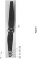
- Figure 3 is an image illustrating a blocking surface of an obstructive object.
- the obstructive object is mounted on a movable object at a location that causes a blocking surface of the obstructive object to partially or completely block an imaging sensor (e.g., the imaging sensor 120 and/or the imaging device 216).
- the obstructive object includes a blocking surface of a propeller 300 (also referred to as propeller blade 300) of the movable object 102 as shown in Figure 3 .
- the blocking surface of the obstructive object comprises a lower surface of the propeller blade 300, such as the lower surface of the propeller blade 300 facing the imaging sensors 120.
- the lower surface of the propeller blade 300 can be illuminated by one or more illumination source mounted on the movable object 102 (e.g., Figures 4A-4B ).
- the propeller 300 is a component of the movement mechanisms 114.
- one or more propellers 300 can be coupled to the movable object 102 using one or more support elements (e.g., drive shafts) and/or one or more actuating elements (e.g., the movable object actuators 212).
- the propeller 300 can be powered by the movable object actuators 212 to rotate to cause the movable object 102 to lift and/or thrust.
- the obstructive object includes another component of the movable object 102, such as an arm of the movable object or a landing gear of the movable object.
- the propeller 300 is mounted on the movable object 102 at a location that causes one or more blades of the propeller 300, e.g., one or more blocking surfaces of the one or more blades respectively, to partially or completely block an imaging sensor 120 during rotation of the propeller 300.
- one or more images captured by the imaging sensor 120 may include at least a portion of the blocking surface of the propeller blade 300 at one or more locations within the one or more images respectively.
- the captured images are processed using a predetermined template related to the obstructive object, e.g., the propeller blade 300, for detecting and/or removing the images of at least a portion of the propeller blade 300.
- the obstructive object e.g. the propeller blade 300
- the obstructive object includes one or more markers, i.e. stripes 302, 304, 306, and 308 distributed on the blocking surface of the blade 300.
- the markers 302-308 are distributed on a lower surface of the blade 300 that faces the imaging sensors 120.
- the propeller 300 includes one blade, two blades (such as two opposing blades as shown in Figure 3 ), three blades, or any other number of blades.
- the markers are distributed on only one blade of the one or more blades of the propeller 300 (e.g., Figure 3 ). In some other embodiments, the markers are distributed on more than one blade of two or more blades of the propeller 300.
- the markers are distributed on each blade of the two or more blades of the propeller 300.
- Each blade of the one or more blades of the propeller 300 may be flat.
- each blade of the one or more blades of the propeller 300 may have a blade angle that varies from the blade root to the blade tip, thus the markers 302-308 can also be distributed on both upper and lower surfaces of the blade facing the imaging sensor 120 or the imaging device 216.
- each marker of the markers 302-308 is made of a reflective material (e.g., phosphor).
- the makers include one or more stripes as illustrated in Figure 3 .
- each marker is an arc stripe on a respective circle of a plurality of circles, so that each arc stripe forms a motion trail in a respective circle of the plurality of circles when the propeller blade 300 is in a rotational motion.
- the marker 302 is an arc stripe on a portion of a first circle
- the marker 304 is an arc stripe on a portion of a second circle that is different from the first circle.
- the plurality of circles are concentric circles.
- a common central axis of the plurality of concentric circles is a central axis (through center point 310) around which the blade 300 is configured to rotate.
- a marker has other suitable shape, such as a rectangle, a square, or other polygons.
- the one or more markers 302-308 include multiple groups of stripes with different widths.
- the multiple groups of stripes may be alternatingly distributed on the blocking surface of the blade 300 such that the stripes on the obstructive object can be sufficiently distinguished from other objects in the environment with a stripe shape or with a stripe pattern, such as an obstacle or a target with a stripe pattern.
- the markers (stripes) 302 and 306 belong to a first group of stripes each having a first width
- the markers (stripes) 304 and 308 belong to a second group of stripes each having a second width.
- the second width may be smaller than the first width.
- the first width is 1-5 times the second width.
- the first width is 1.5-2.5 times the second width.
- each group of stripes includes 1-5 stripes.
- each group of stripes includes 3-5 reflective stripes.
- the markers are distributed near an outer edge of the blade 300, which is the farther end of the blade 300 from the central axis or the center 310.
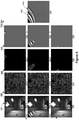
- Figures 4A-4B illustrate a pair of images comparing a movable object without ( Figure 4A ) and with ( Figure 4B ) an illumination source shining at the markers on a propeller blade 300, in accordance with some embodiments.
- an illumination source is mounted on the movable object 102 to illuminate the one or more markers 302-308.
- the illumination source includes a fluorescent light source, an incandescent light source, a discharge light source, a neon and argon light source, a plasma light source, a light-emitting diode (LED) light source, an organic LED (OLED) light source, or any other suitable light source.
- the illuminating source includes one or more white LEDs mounted on the removable object 102.
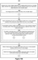
- FIG. 5 is a flow diagram illustrating a method 500 for preparing a motion trail template used for image processing, in accordance with some embodiments.
- the motion trail template includes information indicating motion and locations of an obstructive object, e.g., the propeller blade 300 or a blocking surface of the propeller blade 300, during rotation of the obstructive object.
- the method 500 is performed by an electronic device such as the computing device 110, the control unit 108, or the movable object 102 ( Figure 1 ).
- the method 500 is performed by other electronic device(s), such as a mobile device or a computing device paired with the control unit 108 for operating the movable object 102.
- Figure 5 corresponds to instructions stored in computer memories or other computer-readable storage mediums of the corresponding device(s).
- Figure 6 illustrates an exemplary process of preparing a motion trail template 640 for image processing, in accordance with some embodiments.
- the images processed at one or more steps of method 500 are further illustrated in Figure 6 , which uses the propeller blade 300 as an example of the obstructive object, in accordance with some embodiments.
- the electronic device acquires (502) a plurality of images, such as images 602, 604, and 606 in Figure 6 .
- the plurality of images are captured by an imaging device, such as the imaging sensor(s) 120 or the imaging device 216 borne by the movable object 102.
- the plurality of images can be a series of image frames of a video captured at a periodic rate.
- each image of the plurality of images is a short-exposure image, e.g., taken when the obstructive object moves relatively slowly or with a short exposure time.
- each image of the plurality of images is a long-exposure image, e.g., taken when the obstructive object moves relatively fast or with a long exposure time.
- each image of the plurality of images includes at least a portion of the obstructive object at one or more respective locations.
- each image of images 602, 604, and 606 of Figure 6 includes a portion of the blocking surface of the propeller blade 300 at different locations.
- the electronic device selects (504) a certain image, such as image 602 ( Figure 6 ), from the plurality of images.
- the selected image includes at least a portion of the obstructive object at a projected location.
- image 602 includes a portion of the propeller blade 300 located at a certain location.
- the electronic device obtains (506) edges of one or more objects including the obstructive object in the selected image, e.g., image 602, as illustrated in image 612.
- an edge detection algorithm such as Canny edge detection algorithm, is used by the electronic device to extract edge information in image 602.
- One or more threshold values for the algorithm are selected for effectively identifying the edges with high contrast between the brighter marker area and the darker blade area ( Figure 4B ).
- the electronic device selects (508), from the detected edges in image 602 in step 506, edges of the markers on the obstructive object and/or edges of the obstructive object. For example, the electronic device selects markers edges and/or the blade edges in image 602, as illustrated in image 622.
- Step 508 can be performed manually. Alternatively or additionally, step 508 can be performed automatically, e.g., by pattern recognition process using one or more pre-set criteria and/or pattern(s) for identifying the marker edges and blade edges.
- one or more edges, including blade edges and marker edges are selected to form one or more enclosed areas, as shown in image 622.
- the electronic device obtains (510) a mask, e.g., mask 632, which corresponds to the processed image at step 508, e.g., image 622.
- Mask 632 identifies at least a portion of the obstructive object, e.g., the blade 300, at a certain location.
- mask 632 is formed by filling different colors in different types of regions. For example, the regions corresponding to markers on the blade in image 622 are filled with white color, the regions corresponding to the rest of the blade areas (e.g., the rest of the areas within the enclosed areas) are filled with black color, and the rest of the regions (e.g., uncertain regions) in image 622 are filled with gray color.
- method 500 proceeds to determine (512) whether the currently processed image, e.g., image 602, is the last image of the plurality of acquired images at step 502. In other words, it is determined (512) whether all images of the plurality of images acquired at step 502 have been processed. In accordance with a determination that the currently processed image is not the last image of the plurality of acquired images (512-No), the electronic device proceeds to process the next image of the plurality of images (514). For example as shown in Figure 6 , other images, e.g., images 604 and 606, include at least a portion of the obstructive object (the blade 300) at respective locations.
- the images 604 and 606 are processed using edge detection algorithms to detect (506) all the edges in the images (as shown in images 614 and 616 respectively), to select (508) the marker edges and/or blade edges (as shown in images 624 and 626 respectively), and to obtain (510) masks 634 and 636 by filling different colors in corresponding regions.
- the electronic device merges (516) all masks from the plurality of images to obtain a motion trail template including a plurality of motion trails.
- Each motion trail represents a motion of a marker on the obstructive object during the rotational motion of the obstructive object.
- the electronic device merges all masks, including masks 632, 634, and 636, to obtain a motion trail template 640.
- the motion trail template 640 includes a plurality of motion trails, such as the stripes in Figure 6 .
- each motion trail (e.g., motion trail 642, motion trail 644) illustrates a trail of motion of a marker on the obstructive object during rotation of the obstructive object.
- marker 302 ( Figures 3 and 4B ) corresponds to motion trail 642
- marker 306 corresponds to motion trail 644 ( Figures 3 and 4B ).
- the regions designated as marker regions in all masks are identified as marker regions. However, if a certain region in a first mask is designated as a marker region at step 510, and the same region in a second mask is designated as a blade region at step 510, then this particular region is not designated as a marker region in the motion trail template 640 at the merging step 512.
- the regions designated as marker regions or uncertain regions (e.g., not a marker region or a blade region) in the plurality of masks can be identified as marker regions. For example, if a certain region in a first mask is designated as a marker region at step 510, and the same region in a second mask is designated as an uncertain region at step 510, then this particular region can be identified as a marker region in the motion trail template 640 at the merging step 512.
- the regions designated as blade regions in all masks or the regions designated as blade regions or uncertain regions in all masks are identified as blade regions. For example, if a certain region in a first mask is designated as a blade region at step 510, and the same region in a second mask is designated as a marker region at step 510, then this particular region is not identified as a blade region in the motion trail template 640 at the merging step 512.
- a change of a shape or a change of a boundary of the markers, a gradient transition from a marker region to an obstructive object region (e.g., to a blade region), and/or a change to the illumination effect can cause errors or uncertainties to the edge detection process.
- the motion trail template 640 is further optimized to eliminate errors to provide more accurate motion trail information which is related to the locations of the obstructive object.
- the boundaries of the marker regions and the boundaries of the blade regions are adjusted inward to improve the matching degrees between the markers and the obstructive object in the template and the corresponding markers and the obstructive object in captured images for processing.
- the motion trail template 640 can also be prepared using a long-exposure image (not shown) captured by an imaging sensor (e.g., imaging sensor 120 or imaging device 216). Trails of one or more marks on the obstructive object moving from a first location to a second location can be shown in the long-exposure image.
- the captured long-exposure image can then be manually marked. For example, the trails corresponding to the motion of the markers are designated as marker regions in white color, and the trails corresponding to the motion of the blade are designated as blade regions in black color.
- Figure 7 is a flow diagram illustrating a method 700 for preparing a template used for image processing, in accordance with some embodiments.
- the template includes information indicating projected locations (e.g., possible locations) of an obstructive object, e.g., the propeller blade 300, within an image during rotation of the obstructive object.
- a template can be prepared to include information representing at least a portion of the blade 300 at one or more projected locations (possible locations) in an image captured by the imaging sensor.
- the template includes one or more markers, such as dots, pixels, lines, or a polygon. In some embodiments, the template includes location information and/or pixel value of each marker.
- the method 700 is performed by an electronic device such as the computing device 110, the control unit 108, or the movable object 102 ( Figure 1 ). In some other embodiments, the method 700 is performed by other electronic device(s), such as a mobile device or a computing device paired with the control unit 108 for operating the movable object 102. Operations performed in Figure 7 correspond to instructions stored in computer memories or other computer-readable storage mediums of the corresponding device(s).
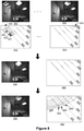
- Figure 8 illustrates an exemplary process of preparing template 852 for image processing, in accordance with some embodiments. One or more steps of method 700 regarding processing the images to prepare the template are further illustrated in Figure 8 , which uses the propeller blade 300 as an example of the obstructive object, in accordance with some embodiments.
- the electronic device selects (702) a plurality of images, such as images 802 and 804 in Figure 8 .
- the plurality of images are captured by an imaging device, such as the imaging sensor(s) 120 or the imaging device 216 borne by the movable object 102.
- the plurality of images can be a series of image frames of a video captured at a periodic rate.
- each image of the plurality of images is a short-exposure image taken when the obstructive object moves relatively slowly.
- each image of the plurality of images includes at least a portion of the obstructive object, such as the propeller blade 300, at a respective location.
- the electronic device selects (704) a certain image, such as image 802, from the plurality of images for processing.
- the selected image includes at least a portion of the obstructive object at a certain location.
- image 802 or the corresponding illustrative sketch 812 includes a portion of the propeller blade 300 located at a certain location.
- the electronic device identifies (706) a collection of points or a line representing the location of the portion of the obstructive object in the currently processed image.
- the collection of points or the line is associated with a rotation angle of the corresponding location of the portion of the obstructive object.
- the electronic device identifies line 822 which represents the projected location of at least a portion of the blade 300, as illustrated in image 812.
- the line 822 is associated with a rotation angle of the projected location.
- the line 822 is a longitudinal axis of symmetry of the blade 300.
- the identified collections of points, such as lines 822, 824, 826, 828, and 830, of the respective plurality of images are evenly distributed as illustrated in image 812.
- the electronic device identifies (708) a first group of markers in the selected image, such as image 802/812.
- the first group of markers such as markers 831, 832, and 833, are identified to be distributed on line 822 and at centers of the marker regions (e.g., stripes) and blade regions on blade 300.
- the first group of markers are pixels from captured image 802 that are located on line 822 and at centers of the marker regions and blade regions on blade 300. Each pixel has a pixel value including brightness information and/or color information of the corresponding pixel in captured image 802.
- method 700 proceeds to determine (710) whether the currently processed image, e.g., image 802, is the last image of the plurality of acquired images at step 702. In other words, it is determined (710) whether all images of the plurality of images acquired at step 702 have been processed. In accordance with a determination that the currently processed image is not the last image of the plurality of acquired images (710-No), the electronic device proceeds to process the next image of the plurality of images (712). For example as shown in Figure 8 , other images, e.g., image 804, include at least a portion of the obstructive object (the blade 300) at respective locations.
- the image 804 is processed by identifying the line 830 and the first group of markers (e.g., 834) in image 804, as shown in corresponding illustrative sketch 814.
- Other images are also processed by identifying the respective lines (e.g., 824, 826, and 828) and the first group of markers in corresponding images.
- the electronic device merges (714) the identified first group of markers from the plurality of images to obtain a preliminary template 842 (corresponding to image 840).
- the preliminary template 842 includes a plurality of collections of points, such as lines 822, 824, 826, 828, and 830, indicating projected locations of the blade 300 during rotation and first group of markers distributed on respective lines.
- the electronic device further adds (716) a second group of markers to the preliminary template 842 to obtain the template 852 (corresponding to image 850).
- the second group of markers are distributed on one or more trails (e.g., trail 858, Figure 8 ) in motion trail template 640 ( Figure 6 ) obtained using method 500 ( Figure 5 ).
- a plurality of markers in the second group of markers are added on motion trail 858 and between markers from the first group of markers, such as between marker 854 on line 822 and marker 856 on line 824.
- the total number of markers in the second group of markers added on each motion trail, such as motion trail 858 is in a range from 200 to 400.
- the template 852 includes the first group of markers (identified at step 708) and the second group of markers (added at step 716).
- one or more markers of the first group and the second group of markers in template 852 are corresponding pixels from respective capture images (e.g., image 802, image 804, etc.). Each pixel has a pixel value including brightness information and/or color information of the pixel in the corresponding captured image.
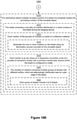
- Figure 9 is a flow diagram illustrating a method 900 for supporting image processing for movable object 102, in accordance with some embodiments.
- the method 900 is performed by an electronic device such as the computing device 110, the control unit 108, or the movable object 102 ( Figure 1 ).
- the method 900 is performed by other electronic device(s), such as a mobile device or a computing device paired with the control unit 108 for operating the movable object 102. Operations performed in Figure 9 correspond to instructions stored in computer memories or other computer-readable storage mediums of the corresponding device(s).
- the electronic device acquires (902) an image captured by an imaging device (e.g., imaging sensor 120 or imaging device 216) borne by the movable object 102.
- the imaging device is at least partially blocked by a blocking surface of an obstructive object, such as propeller blade 300 of Figure 3 .
- the obstructive object can have a fixed configuration, a periodic configuration, or otherwise a predictable configuration relative to the imaging device.
- the image includes at least a portion of the obstructive object at a certain location.
- a relative position between the imaging device and the obstructive object, such as between the imaging sensor 120 and the propeller blade 300 is fixed.
- a relative position between the imaging device and the obstructive object can be determined or predicted.
- position information of the imaging device 216 can be obtained from the carrier 104 to determine the relative position between the imaging device 216 and the propeller blade 300 when the imaging device captures the image.
- the captured image is transmitted from the imaging device to the remote unit 108 or the computing device 110 for processing.
- method 900 is performed in real time as the movable object 102 moves and captures images.
- the electronic device collects (904) pixels in the acquired image corresponding to the markers, including the first group and second group of markers, in template 852 of Figure 8 .
- the electronic device determines (906) whether pixel values of one or more collected pixels corresponding to the first group of markers on each line of a plurality of lines in template 852 satisfy predetermined criteria.
- the electronic device selects pixels in the acquired image corresponding to the first group of pixels located one each line of the plurality of lines (e.g., 822, 824, 826, 828, and 830) in template 852 of Figure 8 , and compares the selected pixel values with the corresponding pixel values in the template 852.
- difference(s) between the selected pixel values and pixel values of markers on a certain line in the template 852 is within a predetermined threshold, it is determined that at least a portion of the obstructive object is located on the certain line in the acquired image. Otherwise, it is determined that the obstructive object is not located on this line in the acquired image.
- the difference(s) between the selected pixel values and pixel values of at least 1/3 of all markers on a certain line in the template 852 is within a predetermined threshold, it is determined that at least a portion of the obstructive object is located on the certain line in the acquired image.
- the electronic device first selects pixels from the acquired image that corresponds to the first group of markers on the plurality of lines in template 852. For each selected pixel, the electronic device then selects one or more neighboring pixels located in a neighboring region, such as a neighboring square or a neighboring circle, with the selected pixel as the center, the selected pixels in the neighboring region are located on one or more trails in the motion trail template 640 of Figure 6 . For example, the electronic device selects pixels located on one or more trails and in a neighboring square region of 21 ⁇ 21 pixels. In some embodiments, the electronic device calculates one or more statistical values for each pixel on the lines using the neighboring pixels.
- a neighboring region such as a neighboring square or a neighboring circle
- the electronic device calculates a mean value of pixels located in the marker regions (bright_mean), a mean value of pixels located in the blade regions (dark_mean), a variation value of the pixels located in the marker regions (bright_var) (such as a standard deviation, an average absolute deviation, a median absolute deviation, or a maximum absolute deviation), and/or a variation value of the pixels located in the blade regions (dark_var).
- the one or more calculated statistical values are compared to one or more corresponding predetermined threshold values.
- the dark_mean value is less than a predetermined threshold value of 10
- the bright_var value is less than a predetermined threshold value of 70
- the dark_var value is less than a predetermined threshold value of 70
- this particular selected pixel exists on the obstructive object (e.g., blade 300) in the acquired image.
- the obstructive object e.g., blade 300
- the obstructive object is located at a location corresponding to this line in the acquired image.
- the electronic device determines (908) the acquired image does not include an image of the obstructive object, e.g., the blade 300, in the acquired image.
- the electronic device identifies (910) that at least portion of the obstructive object, e.g., the blade 300, appears in one or more locations corresponding to the one or more lines respectively within the acquired image.
- the electronic device further determines (912) whether the acquired image is a long-exposure image or a short-exposure image. In some embodiments, the electronic device determines whether at least a portion of the obstructive object, e.g., blade 300, covers a predetermined area in template 852. For example, the electronic device determines whether a portion of the obstructive object covers at least 2/3 of all lines in template 852. When the electronic device determines, from results of step 906, that a portion of the blade 300 exists on less than 2/3 of all lines within the acquired image, the electronic device determines that the acquired image is a short-exposure image (912-Short-exposure).
- the electronic device determines that the acquired image is a short-exposure image (912-Short-exposure).
- the electronic device eliminates (914) areas corresponding to the obstructive object at one or more identified rotation angles. For example, the portion of the blade 300 determined to locate at the one or more lines at step 906 are eliminated, such that the portion of the blade 300 is not mistaken as an obstacle or a target in the movable object environment.
- the electronic device determines that the acquired image is a long-exposure image (912-Long-exposure). Motion blur of the blade 300 may occur in a long-exposure image. Some identified blade regions in the long-exposure image may not block an object (e.g., an obstacle or a target) in the movable object environment. As such, there is no need to eliminate all the image information corresponding to the identified blade regions.
- the electronic device identifies (916) a blur region and a sharp region in the long-exposure image using any suitable image processing technique(s). In some embodiments, the electronic device eliminates (918) pixels in the identified sharp region, and preserves (918) pixels in the identified blur region. In some alternative embodiments, the electronic device eliminates pixels corresponding to the markers (stripes) on the obstructive object, e.g., stripes on blade 300, and preserves the rest of the pixels in the acquired long-exposure image for further imaging processing.
- other methods can be used for performing image processing alternative to or in combination with the methods discussed above.
- a plurality of images including obstructive objects at one or more projected locations are first manually and/or automatically marked.
- the marked images are fed to an algorithm for training the machine learning model.
- the trained model can be used for detecting the obstructive objects in an incoming captured image.
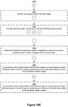
- Figures 10A-10F are a flow diagram illustrating a method 1000 for supporting image processing for movable object 102, in accordance with some embodiments.
- the method 1000 is performed at a device, such as the movable object 102, the imaging sensor 120, the image device 216, the control unit 108, and/or the computing device 110.
- the obstructive object includes propeller 300 (e.g., a propeller blade) of the movable object, an arm of the movable object, a landing gear of the movable object, or any other component of the movable object that may partially or completely block the imaging sensor 120 and/or the imaging device 216.
- propeller 300 e.g., a propeller blade
- the device acquires (1002) one or more images.
- the one or more images are captured by an imaging device (e.g., the imaging sensor 120 or the imaging device 216) borne by the movable object 102.
- the imaging device is at least partially blocked by an obstructive object (or a blocking surface of the obstructive object), such as the propeller blade 300, attached to the movable object 102.
- the imaging device such as the imaging sensor 120
- the imaging device is (1008) fixedly mounted on the movable object 102, thus a relative position between the imaging sensor 120 and the propeller blade 300 rotated to a certain location is fixed.
- the imaging device, such as the imaging device 216 is borne by the carrier 104 and the position information of the imaging device 216 can be determined using one or more sensors attached to the carrier 104.
- the obstructive object includes (1010) at least a portion of the blade 300 of a propeller system for providing a motion of the movable object 102.
- the obstructive object includes (1012) a plurality of markers, i.e., stripes 302, 304, 306, and 308, Figure 3 , distributed on a blocking surface, e.g., a lower surface, of the obstructive object facing the imaging device of the movable object 102.
- each marker of the plurality of markers is (1014) made of a reflective material.
- the movable object 102 includes an illumination source configured to illuminate (1016) the one or more reflective markers on the blade 300, as illustrated in Figure 4B .
- each marker is (1018) an arc stripe on a respective concentric circle of a plurality of concentric circles.
- the plurality of concentric circles have a common central axis around which the blade 300 is configured to rotate.
- the plurality of markers includes (1020) multiple groups of stripes with different widths. For example, each stripe of a first group of stripes (e.g., 304, 308, Figure 3 ) has a first width, and each stripe in a second group of stripes (e.g., 302, 306, Figure 3 ) has a second width that is 1.5-2.5 times the first width.
- the multiple groups of strips are alternatingly distributed near an outer edge of the blade 300 as shown in Figure 3 .
- each group of stripes includes (1022) 3 to 5 stripes.
- the device applies (1004) a template (e.g., the template 852 determined using methods 500 and 700) to the one or more acquired images to obtain one or more projected locations of the obstructive object, e.g., propeller blade 300, within the one or more acquired images.
- the template 852 includes (1024) a pattern representing one or more projected locations of at least portion of the obstructive object (e.g., propeller blade 300) during a rotational motion of the obstructive object.
- the template 852 ( Figure 8 ) includes (1026) one or more collections of points, such as lines (e.g., lines 822, 824, 826, 828, and 830, Figure 8 ) respectively representing the one or more projected locations of the obstructive object (e.g., the propeller blade 300) during the rotational motion. Each line is associated with a rotation angle of a corresponding projected location.
- the template 852 includes other markers, such as dots or polygons, to represent the one or more projected locations of the obstructive object.
- a respective line of the one or more lines in the template 852 is (1030) a longitudinal axis of symmetry of the blocking surface of the obstructive object, such as the propeller blade 300.
- the template 852 includes (1032) a first group of markers (e.g., markers 831, 832, 833, image 812, Figure 8 ) distributed on the one or more lines (e.g., line 822, image 812, Figure 8 ).
- the markers distributed on a respective line, e.g., line 822 comprise (1032) a first set of markers located at centers of stripes on the propeller blade 300, such as markers 832 and 833.
- the markers distributed on line 822 also includes (1032) a second set of markers located at centers of intervals between two adjacent stripes, i.e., blade regions, on the propeller blade 300, such as marker 831.
- the template 852 further includes (1034) a second group of markers (e.g., marker 860 in Figure 8 ) distributed on trails (e.g., trail 858, Figure 8 ) from the motion trail template 640 ( Figure 6 ).
- the motion trail template 640 includes trails indicating motion of the stripes on the propeller blade 300 during the rotational motion of the propeller blade 300.
- the number of markers in the second group of markers on each trail is in a range between 200 to 400.
- the device detects (1006) at least portion of the blocking surface of the obstructive object (e.g., the propeller blade 300) at the one or more projected locations within the one or more images acquired at step 1002. In some embodiments, the device determines (1028) whether at least portion of the propeller blade 300 are located on the one or more lines (e.g., lines 822, 824, 826, 828, and 830, Figure 8 ) in a certain image.
- the one or more lines e.g., lines 822, 824, 826, 828, and 830, Figure 8
- the device collects (1036) pixels in a certain acquired image corresponding to the first group of markers and the second group of markers in the template 852.
- the template 852 only the pixels in the acquired image that correspond to the first group and the second group of markers are to be considered. This can reduce computing workload of the device and improve efficiency for image processing, as there is no need to examine each pixel in the acquired image.
- the device determines (1038) whether pixel values of the collected pixels corresponding to the first group of markers on each line satisfy predetermined criteria. For example, the device compares (1042) the pixel values of the collected pixels in the acquired image with the pixel values (e.g., reference pixel values) of corresponding pixels (e.g., reference pixels) obtained from images for making the template 852. The device compares the difference with a predetermined threshold value.
- a plurality of neighboring pixels and corresponding to the second group of markers in template 852 are identified.
- the device calculates (1044) one or more statistical values of the pixel values of the collected pixels. For example, the device calculates one or more statistical values based on those neighboring pixels for each pixel on the line. For example, for a particular pixel on a certain line, a mean value for all neighboring pixels in the stripe regions (e.g., with brighter color), a mean value for all neighboring pixels in the blade regions (e.g., with darker color), a deviation value for all neighboring pixels in the stripe regions, and a deviation value for all neighboring pixels in the blade regions are calculated.
- the device compares (1046) the one or more statistical values with one or more predetermined threshold values (as discussed in method 900 with reference to Figure 9 ).
- the device identifies (1040) that the obstructive object (e.g., the propeller blade 300) exists at a first rotation angle associated with the first line in the acquired image being processed.
- the obstructive object e.g., the propeller blade 300
- the device further determines (1048) whether a total number of pixels satisfying the predetermined criteria and distributed on the first line is greater than a predetermined threshold number. For example, it is determines whether more than 1/3 of all pixels on the first line satisfy the predetermined criteria. In accordance with a determination that the total number of pixels distributed on the first line is greater than the predetermined threshold number, the device identifies (1050) that the propeller blade 300 exists at a first rotation angle associated with the first line in the first image.
- the device further identifies (1052) an exposure type of the acquired first image. For example, the device determines (1056) whether the blocking surface of the obstructive object (e.g., the propeller blade 300) is identified to exist at more than a predetermined number of angles (corresponding to the lines) within the first image. In an example, the device determines whether at least portion of the propeller blade 300 is identified to exist at no less than 2/3 of all lines within the first image. The device then processes (1054) the first image in accordance with the identified exposure type.
- the blocking surface of the obstructive object e.g., the propeller blade 300
- the first image is identified to be short-exposure image.
- the device eliminates (1058) areas in the first image corresponding to the propeller blade 300 at one or more identified rotation angles (corresponding lines).
- the first image is identified to be long-exposure image.
- the device eliminates (1060) areas in the first image corresponding to stripes on the propeller blade 300 at the identified rotation angles (corresponding lines).
- the device in accordance with a determination that the first image is a long-exposure image (1062), the device further identifies (1064) a blur region and a sharp region of the propeller blade 300 in the first image. The device then eliminates (1066) pixels in the identified sharp region of the propeller blade 300. The device preserves (1068) pixels in the identified blur region of the propeller blade 300.
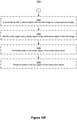
- FIGS 11A-11C are a flow diagram illustrating a method 1100 for controlling movable object 102, in accordance with some embodiments.
- the method 1100 is performed at a device, such as the movable object 102, the imaging sensor 120, the image device 216, the control unit 108, and/or the computing device 110.
- the device acquires (1102) one or more images.
- the one or more images are captured by an imaging device (e.g., the imaging sensor 120 or the imaging device 216) borne by the movable object 102.
- the imaging device is at least partially blocked by an obstructive object, such as the propeller blade 300, attached to the movable object 102.
- the obstructive object includes (1108) at least a portion of the blade 300 of a propeller system for providing a motion of the movable object 102.
- the blade 300 includes (1110) a plurality of reflective stripes, (e.g., stripes 302, 304, 306, and 308, Figure 3 ) distributed on a lower surface of the blade 300 facing the imaging device of the movable object 102.
- the movable object 102 includes an illumination source configured to illuminate the one or more reflective stripes on the blade 300, as illustrated in Figure 4B .
- the device detects (1104) at least portion of the obstructive object (e.g., the propeller blade 300) projected in the acquired one or more images.
- the device applies (1112) a template (e.g., template 852, Figure 8 ) to the one or more images to obtain one or more projected locations of the propeller blade 300 within the acquired one or more images.
- the template includes (1114) one or more lines (e.g., lines 822, 824, 826, 828, and 830, Figure 8 ) respectively representing the one or more projected locations of the propeller blade 300 during a rotational motion. Each line is associated with a rotation angle of a corresponding projected location.
- the template includes (1116) a first group of markers (e.g., markers 831, 832, and 833 of image 812, Figure 8 ) distributed on the one or more lines (e.g., line 822, image 812, Figure 8 ).
- the template further includes (1116) and a second group of markers (e.g., marker 860, image 852, Figure 8 ) distributed on motion trails (e.g., trail 858, Figure 8 ) obtained from the motion trail template 640 ( Figure 6 ).
- the motion trail template 640 includes a plurality of trails (e.g., trail 642, 644, Figure 6 ) corresponding to motion trails of reflective stripes on the blade 300 during the rotational motion of the blade 300.
- the device processes (1106) the acquired one or more images with the projected obstructive object (e.g., propeller blade 300) to assist an operation of the movable object 102.
- the operation of the movable object 102 includes, but is not limited to, obstacle avoidance, navigation and orientation, image capturing and processing, and/or target tracking.
- the device collects (1118) pixels in a certain acquired image (e.g., a first image) corresponding to the first group of markers and the second group of markers in the template 852.
- the device determines (1120) whether pixel values of the collected pixels corresponding to the first group of markers on each line satisfy predetermined criteria. For example, the device compares the pixel values of the collected pixels in the acquired image with the pixel values of corresponding pixels obtained from images for making the template 852. The device compares the difference with a predetermined threshold value.
- a predetermined threshold value For each pixel on a certain line, a plurality of neighboring pixels and corresponding to the second group of markers in template 852 are identified.
- the device calculates one or more statistical values of the pixel values of the collected pixels and compares the one or more statistical values with one or more predetermined threshold values (as discussed in method 900 with reference to Figure 9 ).
- the device identifies (1122) that the obstructive object (e.g., the propeller blade 300) exists at a first rotation angle associated with the first line in the first image.
- the obstructive object e.g., the propeller blade 300
- processing e.g., 1106) the one or more images with the projected obstructive object to assist an operation of the movable object comprises (1124) eliminating at least portion of the obstructive object (e.g., propeller blade 300) projected in the one or more images.
- the device identifies (1126) an exposure type of the acquired first image. For example, the device determines whether the propeller blade 300 is identified to exist at more than a predetermined number of angles (corresponding to the lines) within the first image. In an example, the device determines whether at least portion of the propeller blade 300 is identified to exist at no less than 2/3 of all lines within the first image.
- the first image when at least portion of the propeller blade 300 is identified to exist at less than 2/3 of all lines within the first image, the first image is identified to be short-exposure image. On the other hand, when at least portion of the propeller blade 300 is identified to exist at no less than 2/3 of all lines within the first image, the first image is identified to be long-exposure image.
- the device in accordance with a determination that the first image of the one or more images is a short-exposure image, the device eliminates (1128) pixels in the first image corresponding to the propeller blade 300 at one or more detected locations.
- the device eliminates (1130) areas in the first image corresponding to the reflective stripes on the propeller blade 300 at the detected locations.
- the device further identifies one or more blur regions and one or more sharp regions of the propeller blade 300 in the first image. The device then eliminates pixels in the identified sharp regions of the propeller blade 300. The device preserves pixels in the identified blur regions of the propeller blade 300.
- processor(s) 202 include, without limitation, one or more general purpose microprocessors (for example, single or multi-core processors), application-specific integrated circuits, application-specific instruction-set processors, field-programmable gate arrays, graphics processors, physics processors, digital signal processors, coprocessors, network processors, audio processors, encryption processors, and the like.
- general purpose microprocessors for example, single or multi-core processors
- application-specific integrated circuits for example, application-specific instruction-set processors, field-programmable gate arrays
- graphics processors for example, single or multi-core processors
- physics processors for example, digital signal processors, coprocessors, network processors, audio processors, encryption processors, and the like.
- the storage medium can include, but is not limited to, any type of disk including floppy disks, optical discs, DVD, CD-ROMs, microdrive, and magneto-optical disks, ROMs, RAMs, EPROMs, EEPROMs, DRAMs, VRAMs, DDR RAMs, flash memory devices, magnetic or optical cards, nanosystems (including molecular memory ICs), or any type of media or device suitable for storing instructions and/or data.
- features of the present invention can be incorporated in software and/or firmware for controlling the hardware of a processing system, and for enabling a processing system to interact with other mechanism utilizing the results of the present invention.
- software or firmware may include, but is not limited to, application code, device drivers, operating systems, and execution environments/containers.
- Communication systems as referred to herein optionally communicate via wired and/or wireless communication connections.
- communication systems optionally receive and send RF signals, also called electromagnetic signals.
- RF circuitry of the communication systems convert electrical signals to/from electromagnetic signals and communicate with communications networks and other communications devices via the electromagnetic signals.
- RF circuitry optionally includes well-known circuitry for performing these functions, including but not limited to an antenna system, an RF transceiver, one or more amplifiers, a tuner, one or more oscillators, a digital signal processor, a CODEC chipset, a subscriber identity module (SIM) card, memory, and so forth.
- SIM subscriber identity module
- Communication systems optionally communicate with networks, such as the Internet, also referred to as the World Wide Web (WWW), an intranet and/or a wireless network, such as a cellular telephone network, a wireless local area network (LAN) and/or a metropolitan area network (MAN), and other devices by wireless communication.
- networks such as the Internet, also referred to as the World Wide Web (WWW), an intranet and/or a wireless network, such as a cellular telephone network, a wireless local area network (LAN) and/or a metropolitan area network (MAN), and other devices by wireless communication.
- networks such as the Internet, also referred to as the World Wide Web (WWW), an intranet and/or a wireless network, such as a cellular telephone network, a wireless local area network (LAN) and/or a metropolitan area network (MAN), and other devices by wireless communication.
- WLAN wireless local area network
- MAN metropolitan area network
- Wireless communication connections optionally use any of a plurality of communications standards, protocols and technologies, including but not limited to Global System for Mobile Communications (GSM), Enhanced Data GSM Environment (EDGE), high-speed downlink packet access (HSDPA), high-speed uplink packet access (HSUPA), Evolution, Data-Only (EV-DO), HSPA, HSPA+, Dual-Cell HSPA (DC-HSPDA), long term evolution (LTE), near field communication (NFC), wideband code division multiple access (W-CDMA), code division multiple access (CDMA), time division multiple access (TDMA), Bluetooth, Wireless Fidelity (Wi-Fi) (e.g., IEEE 102.11a, IEEE 102.11ac, IEEE 102.11ax, IEEE 102.11b, IEEE 102.11g and/or IEEE 102.11n), voice over Internet Protocol (VoIP), Wi-MAX, a protocol for e-mail (e.g., Internet message access protocol (IMAP) and/or post office protocol (POP)), instant
Description
- The disclosed embodiments relate generally to image processing and more particularly, but not exclusively, to processing images based on detection of an obstructive object at projected locations within the images captured by a movable object.
- Movable objects such as unmanned aerial vehicles (UAVs) can be used for performing surveillance, reconnaissance, and exploration tasks for military and civilian applications. A movable object may include one or more imaging devices configured to perform specific function(s), such as capturing images of the surrounding environment for obstacle avoidance and/or for target tracking. It is therefore important to maintain information accuracy in the captured images, for example, by detecting and processing image information that may not correspond to obstacle(s) and/or target(s) of the surrounding environment.
-
US 7,196,305 B2 describes an imaging system for a vehicle. The system includes an image sensor generating a plurality of image frames, and a controller coupled to the image sensor. The controller is programmed to detect an obstructed image frame from the plurality of image frames. The obstruction corresponds to a windshield wiper of the vehicle. In response to detecting an obstructed image, the controller optimizes the obstructed image for display or use by a vehicle system. The controller detects an obstructed image by at least one of object sensing confirmation, edge detection, negative shift detection or headlight illumination detection. -
US 9,245,333 B1 -
EP 2 665 039 A2 describes a method for detecting an obstruction within a field of view of a camera from an image captured by the camera. The method includes: analyzing the image by applying edge detection to the image, identifying regions of the image lacking edge content and comparing a size of the identified regions to a threshold; and determining if there is an obstruction based upon a result of said comparison. -
US 2011/043624 A1 describes a method for adapting the driver assistance function, in particular of driver assistance systems based on video images recorded from a vehicle, and a corresponding device for that purpose made up of a camera and processing unit. To adapt the function during rain, the passing of a windshield wiper through the camera image is used to classify individual images and/or portions of images as being of higher or lower quality. - The present invention relates to a method according to
claim 1, a system according to claim 13, an unmanned aerial vehicle according to claim 14, and a computer readable storage medium according to claim 15. Claims 2 to 12 refer to specifically advantageous realizations of the method according toclaim 1. - There is a need for systems and methods for efficiently and accurately processing images captured by one or more imaging devices borne by a movable object for obstacle avoidance, navigation and orientation, image capturing and processing, and/or target tracking. Such systems and methods optionally complement or replace conventional methods for processing images captured by a movable object. One or more obstructive objects borne by the movable object may partially block the imaging devices of the movable object. By using a template to detect the obstructive objects at projected locations in the captured images and to process the images accordingly, embodiments of the present application can significantly improve the efficiency and accuracy of imaging processing for navigation and orientation, image capturing and processing, obstacle avoidance, and/or target tracking. Furthermore, the design flexibility of the movable object can be enhanced by reducing limitations of the relative positions between the imaging devices and the obstructive objects.
-
-
Figure 1 illustrates a movable object environment, in accordance with some embodiments. -
Figure 2 illustrates a movable object, in accordance with some embodiments. -
Figure 3 is an image illustrating a blocking surface of an obstructive object, in accordance with some embodiments. -
Figures 4A-4B illustrate a pair of images comparing a movable object without (Figure 4A ) and with (Figure 4B ) an illumination source shining at markers on a propeller blade, in accordance with some embodiments. -
Figure 5 is a flow diagram illustrating a method for preparing a motion trail template used for image processing, in accordance with some embodiments. -
Figure 6 illustrates an exemplary process of preparing a motion trail template for image processing, in accordance with some embodiments. -
Figure 7 is a flow diagram illustrating a method for preparing a template used for image processing, in accordance with some embodiments. -
Figure 8 illustrates an exemplary process of preparing a template for image processing, in accordance with some embodiments. -
Figure 9 is a flow diagram illustrating a method for supporting image processing for a movable object, in accordance with some embodiments. -
Figures 10A-10F are a flow diagram illustrating a method for supporting image processing for a movable object, in accordance with some embodiments. -
Figures 11A-11C are a flow diagram illustrating a method for controlling a movable object, in accordance with some embodiments. - Reference will now be made in detail to embodiments, examples of which are illustrated in the accompanying drawings. In the following detailed description, numerous specific details are set forth in order to provide a thorough understanding of the various described embodiments. However, it will be apparent to one of ordinary skill in the art that the various described embodiments may be practiced without these specific details. In other instances, well-known methods, procedures, components, circuits, and networks have not been described in detail so as not to unnecessarily obscure aspects of the embodiments.
- The following description uses an unmanned aerial vehicle (UAV) as an example of a movable object. UAVs include, e.g., fixed-wing aircrafts and rotary-wing aircrafts such as helicopters, quadcopters, and aircraft having other numbers and/or configurations of rotors. It will be apparent to those skilled in the art that other types of movable objects may be substituted for UAVs as described below.
- The present invention provides techniques related to processing images captured by UAVs for navigation and orientation, image capturing and processing, obstacle avoidance and/or target tracking. The images can be processed using a template to detect obstructive objects at projected locations in the images. The image processing techniques can provide efficiency and accuracy in obstacle avoidance and/or target tracking, and flexibility in design and manufacture of UAVs. As a result, the cost for designing and manufacturing the movable object with an imaging device onboard can be reduced.
-
Figure 1 illustrates amovable object environment 100, in accordance with some embodiments. Themovable object environment 100 includes amovable object 102. In some embodiments, themovable object 102 includes acarrier 104 and/or apayload 106. Themovable object 102 also includes one or more (e.g., a pair of)imaging sensors 120 for capturing images of surrounding environment. - In some embodiments, the
carrier 104 is used to couple thepayload 106 to themovable object 102. In some embodiments, thecarrier 104 includes an element (e.g., a gimbal and/or damping element) to isolate thepayload 106 from movement of themovable object 102 and/or themovement mechanism 114. In some embodiments, thecarrier 104 includes an element for controlling movement of thepayload 106 relative to themovable object 102. - In some embodiments, the
payload 106 is coupled (e.g., rigidly coupled) to the movable object 102 (e.g., coupled via carrier 104) such that thepayload 106 remains substantially stationary relative tomovable object 102. For example, thecarrier 104 is coupled to thepayload 106 such that the payload is not movable relative to themovable object 102. In some embodiments, thepayload 106 is mounted directly to themovable object 102 without requiring thecarrier 104. In some embodiments, thepayload 106 is located partially or fully within themovable object 102. - The
imaging sensors 120 are mounted to the exterior, located within, or otherwise coupled tomovable object 102. In some embodiments, theimaging sensors 120 are fixedly mounted to themovable object 102. For example, a relative position between acertain imaging sensor 120 and a stationary (or a fixed) component of themovable object 102 is fixed. In some embodiments, theimaging sensors 120 are components of a movableobject sensing system 210, such as a carrier sensing system and/or a payload sensing system. Theimaging sensors 120, along with other components of the movable object sensing system 122, capture environmental information, generates static sensing data (e.g., a single image captured in response to a received instruction) and/or dynamic sensing data (e.g., a series of images captured at a periodic rate, such as a video). More details about theimaging sensors 120 will be discussed with reference toFigure 2 . - In some embodiments, a
control unit 108 communicates with themovable object 102, e.g., to provide control instructions to themovable object 102 and/or to display information received from themovable object 102. Although thecontrol unit 108 is typically a portable (e.g., handheld) device, thecontrol unit 108 need not be portable. In some embodiments, thecontrol unit 108 is a dedicated control device (e.g., for the movable object 102), a laptop computer, a desktop computer, a tablet computer, a gaming system, a wearable device (e.g., glasses, a glove, and/or a helmet), a microphone, a portable communication device (e.g., a mobile telephone) and/or a combination thereof. - In some embodiments, an input device of the
control unit 108 receives user input to control aspects of themovable object 102, thecarrier 104, thepayload 106, and/or a component thereof. Such aspects include, e.g., orientation, position, orientation, velocity, acceleration, navigation, and/or tracking. For example, a position of an input device of the control unit 108 (e.g., a position of a component of the input device) is manually set by a user to a position corresponding to an input (e.g., a predetermined input) for controlling themovable object 102. In some embodiments, the input device is manipulated by a user to input control instructions for controlling the navigation of themovable object 102. In some embodiments, an input device ofcontrol unit 108 is used to input a flight mode for themovable object 102, such as auto pilot or navigation according to a predetermined navigation path. - In some embodiments, a display of the
control unit 108 displays information generated by the movableobject sensing system 210, thememory 204, and/or another system of themovable object 102. For example, the display displays information about themovable object 102, thecarrier 104, and/or thepayload 106, such as position, orientation, orientation, movement characteristics of themovable object 102, and/or distance between themovable object 102 and another object (e.g., a target and/or an obstacle). In some embodiments, information displayed by a display ofcontrol unit 108 includes images captured by an imaging device 216 (Figure 2 ), tracking data (e.g., a graphical tracking indicator applied to a representation of a target), and/or indications of control data transmitted to themovable object 102. In some embodiments, information displayed by the display of thecontrol unit 108 is displayed in substantially real-time as information is received from themovable object 102 and/or as image data is acquired. In some embodiments, the display of thecontrol unit 108 is a touchscreen display. - In some embodiments, the
movable object environment 100 includes acomputing device 110. Thecomputing device 110 is, e.g., a server computer, a cloud server, a desktop computer, a laptop computer, a tablet, or another portable electronic device (e.g., a mobile telephone). In some embodiments, thecomputing device 110 is a base station that communicates (e.g., wirelessly) with themovable object 102 and/or thecontrol unit 108. In some embodiments, thecomputing device 110 provides data storage, data retrieval, and/or data processing operations, e.g., to reduce the processing power and/or data storage requirements of themovable object 102 and/or thecontrol unit 108. For example, thecomputing device 110 is communicatively connected to a database and/or thecomputing device 110 includes a database. In some embodiments, thecomputing device 110 is used in lieu of or in addition to thecontrol unit 108 to perform any of the operations described with regard to thecontrol unit 108. - In some embodiments, the
movable object 102 communicates with acontrol unit 108 and/or acomputing device 110, e.g., viawireless communications 112. In some embodiments, themovable object 102 receives information from thecontrol unit 108 and/or thecomputing device 110. For example, information received by themovable object 102 includes, e.g., control instructions for controllingmovable object 102. In some embodiments, themovable object 102 transmits information to thecontrol unit 108 and/or thecomputing device 110. For example, information transmitted by themovable object 102 includes, e.g., images and/or video captured by themovable object 102. - In some embodiments, communications between the
computing device 110, thecontrol unit 108 and/or themovable object 102 are transmitted via a network (e.g., Internet 116) and/or a wireless signal transmitter (e.g., a long range wireless signal transmitter) such as acellular tower 118. In some embodiments, a satellite (not shown) is a component ofInternet 116 and/or is used in addition to or in lieu of thecellular tower 118. - In some embodiments, information communicated between the
computing device 110, thecontrol unit 108 and/or themovable object 102 include control instructions. Control instructions include, e.g., navigation instructions for controlling navigational parameters of themovable object 102 such as position, orientation, orientation, and/or one or more movement characteristics of themovable object 102, thecarrier 104, and/or thepayload 106. In some embodiments, control instructions include instructions directing movement of one or more of themovement mechanisms 114. For example, control instructions are used to control flight of a UAV. - In some embodiments, control instructions include information for controlling operations (e.g., movement) of the
carrier 104. For example, control instructions are used to control an actuation mechanism of thecarrier 104 so as to cause angular and/or linear movement of thepayload 106 relative to themovable object 102. In some embodiments, control instructions adjust movement of thecarrier 104 relative to themovable object 102 with up to six degrees of freedom. - In some embodiments, control instructions are used to adjust one or more operational parameters for the
payload 106. For example, control instructions include instructions for adjusting an optical parameter (e.g., an optical parameter of the imaging device 216). In some embodiments, control instructions include instructions for adjusting imaging properties and/or image device functions, such as capturing an image, initiating/ceasing video capture, powering animaging device 216 on or off, adjusting an imaging mode (e.g., capturing still images or capturing video), adjusting a distance between left and right components of a stereographic imaging system, and/or adjusting a position, orientation, and/or movement (e.g., pan rate, pan distance) of acarrier 104, apayload 106 and/or animaging device 216. - In some embodiments, when control instructions are received by
movable object 102, the control instructions change parameters of and/or are stored by memory 204 (Figure 2 ) ofmovable object 102. -
Figure 2 illustrates an exemplarymovable object 102, in accordance with some embodiments. Themovable object 102 typically includes one or more processor(s) 202, amemory 204, acommunication system 206, a movableobject sensing system 210, and one ormore communication buses 208 for interconnecting these components. - In some embodiments, the
movable object 102 is a UAV and includes components to enable flight and/or flight control. In some embodiments, themovable object 102 includescommunication system 206 with one or more network or other communications interfaces (e.g., via which flight control instructions are received), one ormore movement mechanisms 114, and/or one or more movable object actuators 212 (e.g., to cause movement ofmovement mechanisms 114 in response to received control instructions). Although themovable object 102 is depicted as an aircraft, this depiction is not intended to be limiting, and any suitable type of movable object can be used. - In some embodiments, the
movable object 102 includes movement mechanisms 114 (e.g., propulsion mechanisms). Although the plural term "movement mechanisms" is used herein for convenience of reference, "movement mechanisms 114" refers to a single movement mechanism (e.g., a single propeller) or multiple movement mechanisms (e.g., multiple rotors). Themovement mechanisms 114 include one or more movement mechanism types such as rotors, propellers, blades, engines, motors, wheels, axles, magnets, nozzles, and so on. Themovement mechanisms 114 are coupled to themovable object 102 at, e.g., the top, bottom, front, back, and/or sides. In some embodiments, themovement mechanisms 114 of a singlemovable object 102 include multiple movement mechanisms of the same type. In some embodiments, themovement mechanisms 114 of a singlemovable object 102 include multiple movement mechanisms with different movement mechanism types. Themovement mechanisms 114 are coupled to themovable object 102 using any suitable means, such as support elements (e.g., drive shafts) and/or other actuating elements (e.g., the movable object actuators 212). For example, amovable object actuator 212 receives control signals from the processor(s) 202 (e.g., via the control bus 208) that activates themovable object actuator 212 to cause movement of amovement mechanism 114. For example, the processor(s) 202 include an electronic speed controller that provides control signals to amovable object actuator 212. - In some embodiments, the
movement mechanisms 114 enable themovable object 102 to take off vertically from a surface or land vertically on a surface without requiring any horizontal movement of the movable object 102 (e.g., without traveling down a runway). In some embodiments, themovement mechanisms 114 are operable to permit themovable object 102 to hover in the air at a specified position and/or orientation. In some embodiments, one or more of themovement mechanisms 114 are controllable independently of one or more of theother movement mechanisms 114. For example, when themovable object 102 is a quadcopter, each rotor of the quadcopter is controllable independently of the other rotors of the quadcopter. In some embodiments,multiple movement mechanisms 114 are configured for simultaneous movement. - In some embodiments, the
movement mechanisms 114 include multiple rotors that provide lift and/or thrust to themovable object 102. The multiple rotors are actuated to provide, e.g., vertical takeoff, vertical landing, and hovering capabilities to themovable object 102. In some embodiments, one or more of the rotors spin in a clockwise direction, while one or more of the rotors spin in a counterclockwise direction. For example, the number of clockwise rotors is equal to the number of counterclockwise rotors. In some embodiments, the rotation rate of each of the rotors is independently variable, e.g., for controlling the lift and/or thrust produced by each rotor, and thereby adjusting the spatial disposition, velocity, and/or acceleration of the movable object 102 (e.g., with respect to up to three degrees of translation and/or up to three degrees of rotation). - In some embodiments, the
memory 204 stores one or more instructions, programs (e.g., sets of instructions), modules, controlling systems and/or data structures, collectively referred to as "elements" herein. One or more elements described with regard to thememory 204 are optionally stored by thecontrol unit 108, thecomputing device 110, and/or another device. In some embodiments,imaging device 216 includes memory that stores one or more parameters described with regard to thememory 204. - In some embodiments, the
memory 204 stores a controlling system configuration that includes one or more system settings (e.g., as configured by a manufacturer, administrator, and/or user). For example, identifying information for themovable object 102 is stored as a system setting of the system configuration. In some embodiments, the controlling system configuration includes a configuration for theimaging device 216. The configuration for theimaging device 216 stores parameters such as position, zoom level and/or focus parameters (e.g., amount of focus, selecting autofocus or manual focus, and/or adjusting an autofocus target in an image). Imaging property parameters stored by the imaging device configuration include, e.g., image resolution, image size (e.g., image width and/or height), aspect ratio, pixel count, quality, focus distance, depth of field, exposure time, shutter speed, and/or white balance. In some embodiments, parameters stored by the imaging device configuration are updated in response to control instructions (e.g., generated by processor(s) 202 and/or received by themovable object 102 fromcontrol unit 108 and/or the computing device 110). In some embodiments, parameters stored by the imaging device configuration are updated in response to information received from the movableobject sensing system 210 and/or theimaging device 216. - In some embodiments, a controlling system performs imaging device adjustment. The imaging device adjustment module stores, e.g., instructions for adjusting a distance between an image sensor and an optical device of an
imaging device 216, e.g., instructions for controlling an imaging device actuator. In some embodiments, one or more instructions for performing imaging device adjustment are stored in thememory 204. - In some embodiments, the controlling system performs an autofocus operation. For example, the autofocus operation is performed, e.g., periodically, when a device determines from image analysis that a focus level has fallen below a focus level threshold, in response a determination that
movable object 102 and/or an image subject (e.g., a target or a remote object) has moved by more than a threshold distance, and/or in response to user input. In some embodiments, user input (e.g., received atcontrol unit 108 and/or computing device 110) initiates and/or adjusts an autofocus mode. In some embodiments, user input indicates one or more regions (e.g., in an image captured byimaging device 216, such as an image displayed bycontrol unit 108 and/or computing device 110) to be used and/or prioritized for an autofocus operation. In some embodiments, the autofocus module generates control instructions for moving an optical device relative to an image sensor in accordance with an image distance value determined by an image distance determination module. In some embodiments, one or more instructions for performing an autofocus operation are stored in thememory 204. - In some embodiments, the controlling system performs image distance determination, e.g., to determine an object distance and/or an image distance in accordance with the operations described herein. For example, the image distance determination module uses sensor data from one or more depth sensors and one or more orientation sensors of a movable object to determine an image distance and generate a control instruction for moving an optical device relative to an image sensor in accordance with the determined image distance. In some embodiments, one or more instructions for performing image distance determination are stored in the
memory 204. - The above identified controlling system, modules, and/or programs (e.g., sets of instructions) need not be implemented as separate software programs, procedures or modules, and thus various subsets of these modules may be combined or otherwise re-arranged in various embodiments, and stored in the
memory 204. In some embodiments, the controlling system includes a subset of the modules and data structures identified above. Furthermore, thememory 204 may store additional modules and data structures not described above. In some embodiments, the programs, modules, and data structures stored in thememory 204, or a non-transitory computer readable storage medium ofmemory 204, provide instructions for implementing respective operations in the methods described below. In some embodiments, some or all of these modules may be implemented with specialized hardware circuits that subsume part or all of the module functionality. One or more of the above identified elements may be executed by one ormore processors 202 of themovable object 102. In some embodiments, one or more of the above identified modules are stored on one or more storage devices of a device remote from the movable object (such as memory of thecontrol unit 108, thecomputing device 110, and/or the imaging device 216) and/or executed by one or more processors of a device remote from the movable object 102 (such as processor(s) of thecontrol unit 108, thecomputing device 110, and/or the imaging device 216). - The
communication system 206 enables communication with thecontrol unit 108 and/or thecomputing device 110, e.g., via wireless signals 112. Thecommunication system 206 includes, e.g., transmitters, receivers, and/or transceivers for wireless communication. In some embodiments, the communication is one-way communication, such that data is only received by themovable object 102 from thecontrol unit 108 and/or thecomputing device 110, or vice-versa. In some embodiments, communication is two-way communication, such that data is transmitted in both directions between themovable object 102 and thecontrol unit 108 and/or thecomputing device 110. In some embodiments, themovable object 102, thecontrol unit 108, and/or thecomputing device 110 are connected to theInternet 116 or other telecommunications network, e.g., such that data generated by themovable object 102, thecontrol unit 108, and/or thecomputing device 110 is transmitted to a server for data storage and/or data retrieval (e.g., for display by a website). - The
sensing system 210 of themovable object 102 includes one or more sensors. One or more sensors of the movableobject sensing system 210 are mounted to the exterior, located within, or otherwise coupled to themovable object 102. In some embodiments, one or more sensors of the movableobject sensing system 210 are components of and/or coupled to thecarrier 104, thepayload 106, and/or theimaging device 216. Where sensing operations are described herein as being performed by the movableobject sensing system 210, it will be recognized that such operations are optionally performed by one or more sensors of thecarrier 104, thepayload 106, and/or theimaging device 216 in addition to and/or in lieu of one or more sensors of the movableobject sensing system 210. - The movable
object sensing system 210 includes one ormore image sensors 120, such as image sensor 214 (e.g., a left stereographic image sensor) and/or image sensor 215 (e.g., a right stereographic image sensor).Image sensors 120 capture, e.g., images, image streams (e.g., videos), stereographic images, and/or stereographic image streams (e.g., stereographic videos).Image sensors 120 detect light, such as visible light, infrared light, and/or ultraviolet light. In some embodiments, movableobject sensing system 210 includes one or more optical devices (e.g., lenses) to focus or otherwise alter the light onto one ormore image sensors 120. In some embodiments,image sensors 120 include, e.g., semiconductor charge-coupled devices (CCD), active pixel sensors using complementary metal-oxide-semiconductor (CMOS) or N-type metal-oxide-semiconductor (NMOS, Live MOS) technologies, or any other types of sensors. Theimaging sensors 120 can be used for detecting an object (e.g., an obstacle or a target), detecting location information of the object, generating a depth map (e.g., usingstereographic image sensors 214 and 215), avoiding an obstacle, and/or tracking a target. - In some embodiments, the movable
object sensing system 210 includes one or more audio transducers (e.g., a speaker, a microphone, a parabolic microphone, a sonar system), one or more infrared sensors, one or more sensor pairs (e.g., leftstereographic image sensor 214 and rightstereographic image sensor 215; audio output transducer and audio input transducer; and/or left infrared sensor and right infrared sensor), one or more global positioning system (GPS) sensors, motion sensors (e.g., accelerometers), rotation sensors (e.g., gyroscopes), inertial sensors, proximity sensors (e.g., infrared sensors), and/or weather sensors (e.g., pressure sensor, temperature sensor, moisture sensor, and/or wind sensor). - In some embodiments, sensing data generated by one or more sensors of movable
object sensing system 210 and/or information determined using sensing data from one or more sensors of movableobject sensing system 210 are transmitted to control unit 108 (e.g., via communication system 112). In some embodiments, data generated one or more sensors of movableobject sensing system 210 and/or information determined using sensing data from one or more sensors of movableobject sensing system 210 is stored bymemory 204. -
Figure 3 is an image illustrating a blocking surface of an obstructive object. The obstructive object is mounted on a movable object at a location that causes a blocking surface of the obstructive object to partially or completely block an imaging sensor (e.g., theimaging sensor 120 and/or the imaging device 216). In some embodiments, the obstructive object includes a blocking surface of a propeller 300 (also referred to as propeller blade 300) of themovable object 102 as shown inFigure 3 . In some embodiments, the blocking surface of the obstructive object comprises a lower surface of thepropeller blade 300, such as the lower surface of thepropeller blade 300 facing theimaging sensors 120. The lower surface of thepropeller blade 300 can be illuminated by one or more illumination source mounted on the movable object 102 (e.g.,Figures 4A-4B ). Thepropeller 300 is a component of themovement mechanisms 114. For example, one ormore propellers 300 can be coupled to themovable object 102 using one or more support elements (e.g., drive shafts) and/or one or more actuating elements (e.g., the movable object actuators 212). Thepropeller 300 can be powered by themovable object actuators 212 to rotate to cause themovable object 102 to lift and/or thrust. In some embodiments, the obstructive object includes another component of themovable object 102, such as an arm of the movable object or a landing gear of the movable object. - In some embodiments, the
propeller 300 is mounted on themovable object 102 at a location that causes one or more blades of thepropeller 300, e.g., one or more blocking surfaces of the one or more blades respectively, to partially or completely block animaging sensor 120 during rotation of thepropeller 300. As a result, one or more images captured by theimaging sensor 120 may include at least a portion of the blocking surface of thepropeller blade 300 at one or more locations within the one or more images respectively. In order to detect the location(s) of the blocking surface of the obstructive object, e.g., the blocking surface of thepropeller blade 300, within the captured images, such that the obstructive object, e.g., thepropeller blade 300, is not mistaken as an obstacle or a target, the captured images are processed using a predetermined template related to the obstructive object, e.g., thepropeller blade 300, for detecting and/or removing the images of at least a portion of thepropeller blade 300. - The obstructive object, e.g. the
propeller blade 300, includes one or more markers, i.e.stripes blade 300. For example, the markers 302-308 are distributed on a lower surface of theblade 300 that faces theimaging sensors 120. In some embodiments, thepropeller 300 includes one blade, two blades (such as two opposing blades as shown inFigure 3 ), three blades, or any other number of blades. In some embodiments, the markers are distributed on only one blade of the one or more blades of the propeller 300 (e.g.,Figure 3 ). In some other embodiments, the markers are distributed on more than one blade of two or more blades of thepropeller 300. In one example, the markers are distributed on each blade of the two or more blades of thepropeller 300. Each blade of the one or more blades of thepropeller 300 may be flat. Alternatively, each blade of the one or more blades of thepropeller 300 may have a blade angle that varies from the blade root to the blade tip, thus the markers 302-308 can also be distributed on both upper and lower surfaces of the blade facing theimaging sensor 120 or theimaging device 216. In some embodiments, each marker of the markers 302-308 is made of a reflective material (e.g., phosphor). The makers include one or more stripes as illustrated inFigure 3 . For example, each marker is an arc stripe on a respective circle of a plurality of circles, so that each arc stripe forms a motion trail in a respective circle of the plurality of circles when thepropeller blade 300 is in a rotational motion. For example, themarker 302 is an arc stripe on a portion of a first circle, and themarker 304 is an arc stripe on a portion of a second circle that is different from the first circle. In some embodiments, the plurality of circles are concentric circles. In one example, a common central axis of the plurality of concentric circles is a central axis (through center point 310) around which theblade 300 is configured to rotate. In some other embodiments, a marker has other suitable shape, such as a rectangle, a square, or other polygons. - The one or more markers 302-308 include multiple groups of stripes with different widths. The multiple groups of stripes may be alternatingly distributed on the blocking surface of the
blade 300 such that the stripes on the obstructive object can be sufficiently distinguished from other objects in the environment with a stripe shape or with a stripe pattern, such as an obstacle or a target with a stripe pattern. For example, the markers (stripes) 302 and 306 belong to a first group of stripes each having a first width, and the markers (stripes) 304 and 308 belong to a second group of stripes each having a second width. The second width may be smaller than the first width. In some examples, the first width is 1-5 times the second width. In some preferable embodiments, the first width is 1.5-2.5 times the second width. In some embodiments, each group of stripes includes 1-5 stripes. In some preferable embodiments, each group of stripes includes 3-5 reflective stripes. In some embodiments as illustrated inFigure 3 , the markers are distributed near an outer edge of theblade 300, which is the farther end of theblade 300 from the central axis or thecenter 310. -
Figures 4A-4B illustrate a pair of images comparing a movable object without (Figure 4A ) and with (Figure 4B ) an illumination source shining at the markers on apropeller blade 300, in accordance with some embodiments. In some embodiments, an illumination source is mounted on themovable object 102 to illuminate the one or more markers 302-308. In some embodiments, the illumination source includes a fluorescent light source, an incandescent light source, a discharge light source, a neon and argon light source, a plasma light source, a light-emitting diode (LED) light source, an organic LED (OLED) light source, or any other suitable light source. In some embodiments, the illuminating source includes one or more white LEDs mounted on theremovable object 102. As compared inFigures 4A and 4B , with an illumination source shinning at the markers on theblade 300, the contrast between the marker areas 302-308 and the blade areas 402-408 is enhanced. This is beneficial for marking and detecting positions of theblade 300 in images captured by imagingsensors 120. More details will be discussed in the present disclosure with reference tomethod 500 inFigure 5 ,method 700 inFigure 7 , andmethod 900 inFigure 9 . -
Figure 5 is a flow diagram illustrating amethod 500 for preparing a motion trail template used for image processing, in accordance with some embodiments. The motion trail template includes information indicating motion and locations of an obstructive object, e.g., thepropeller blade 300 or a blocking surface of thepropeller blade 300, during rotation of the obstructive object. In some embodiments, themethod 500 is performed by an electronic device such as thecomputing device 110, thecontrol unit 108, or the movable object 102 (Figure 1 ). In some other embodiments, themethod 500 is performed by other electronic device(s), such as a mobile device or a computing device paired with thecontrol unit 108 for operating themovable object 102. Operations performed inFigure 5 correspond to instructions stored in computer memories or other computer-readable storage mediums of the corresponding device(s).Figure 6 illustrates an exemplary process of preparing amotion trail template 640 for image processing, in accordance with some embodiments. The images processed at one or more steps ofmethod 500 are further illustrated inFigure 6 , which uses thepropeller blade 300 as an example of the obstructive object, in accordance with some embodiments. - The electronic device acquires (502) a plurality of images, such as
images Figure 6 . The plurality of images are captured by an imaging device, such as the imaging sensor(s) 120 or theimaging device 216 borne by themovable object 102. The plurality of images can be a series of image frames of a video captured at a periodic rate. In some embodiments, each image of the plurality of images is a short-exposure image, e.g., taken when the obstructive object moves relatively slowly or with a short exposure time. In some embodiments, each image of the plurality of images is a long-exposure image, e.g., taken when the obstructive object moves relatively fast or with a long exposure time. In some embodiments, each image of the plurality of images includes at least a portion of the obstructive object at one or more respective locations. For example, each image ofimages Figure 6 includes a portion of the blocking surface of thepropeller blade 300 at different locations. - With regard to the process of preparing the motion trail template, the electronic device selects (504) a certain image, such as image 602 (
Figure 6 ), from the plurality of images. The selected image includes at least a portion of the obstructive object at a projected location. For example,image 602 includes a portion of thepropeller blade 300 located at a certain location. The electronic device obtains (506) edges of one or more objects including the obstructive object in the selected image, e.g.,image 602, as illustrated inimage 612. In some embodiments, an edge detection algorithm, such as Canny edge detection algorithm, is used by the electronic device to extract edge information inimage 602. One or more threshold values for the algorithm are selected for effectively identifying the edges with high contrast between the brighter marker area and the darker blade area (Figure 4B ). - In some embodiments, the electronic device selects (508), from the detected edges in
image 602 instep 506, edges of the markers on the obstructive object and/or edges of the obstructive object. For example, the electronic device selects markers edges and/or the blade edges inimage 602, as illustrated inimage 622. Step 508 can be performed manually. Alternatively or additionally, step 508 can be performed automatically, e.g., by pattern recognition process using one or more pre-set criteria and/or pattern(s) for identifying the marker edges and blade edges. In some embodiments, one or more edges, including blade edges and marker edges, are selected to form one or more enclosed areas, as shown inimage 622. - In some embodiments, the electronic device obtains (510) a mask, e.g.,
mask 632, which corresponds to the processed image atstep 508, e.g.,image 622.Mask 632 identifies at least a portion of the obstructive object, e.g., theblade 300, at a certain location. In some embodiments,mask 632 is formed by filling different colors in different types of regions. For example, the regions corresponding to markers on the blade inimage 622 are filled with white color, the regions corresponding to the rest of the blade areas (e.g., the rest of the areas within the enclosed areas) are filled with black color, and the rest of the regions (e.g., uncertain regions) inimage 622 are filled with gray color. - In some embodiments,
method 500 proceeds to determine (512) whether the currently processed image, e.g.,image 602, is the last image of the plurality of acquired images atstep 502. In other words, it is determined (512) whether all images of the plurality of images acquired atstep 502 have been processed. In accordance with a determination that the currently processed image is not the last image of the plurality of acquired images (512-No), the electronic device proceeds to process the next image of the plurality of images (514). For example as shown inFigure 6 , other images, e.g.,images images images images masks - In accordance with a determination that the currently processed image is the last image of the plurality of acquired images (512-Yes), the electronic device merges (516) all masks from the plurality of images to obtain a motion trail template including a plurality of motion trails. Each motion trail represents a motion of a marker on the obstructive object during the rotational motion of the obstructive object. For example, the electronic device merges all masks, including
masks motion trail template 640. Themotion trail template 640 includes a plurality of motion trails, such as the stripes inFigure 6 . In some embodiments, each motion trail (e.g.,motion trail 642, motion trail 644) illustrates a trail of motion of a marker on the obstructive object during rotation of the obstructive object. For example, marker 302 (Figures 3 and4B ) corresponds tomotion trail 642,marker 306 corresponds to motion trail 644 (Figures 3 and4B ). - In some embodiments, during the merging process at
step 516, only the regions designated as marker regions in all masks are identified as marker regions. However, if a certain region in a first mask is designated as a marker region atstep 510, and the same region in a second mask is designated as a blade region atstep 510, then this particular region is not designated as a marker region in themotion trail template 640 at the mergingstep 512. - In some other embodiments, the regions designated as marker regions or uncertain regions (e.g., not a marker region or a blade region) in the plurality of masks can be identified as marker regions. For example, if a certain region in a first mask is designated as a marker region at
step 510, and the same region in a second mask is designated as an uncertain region atstep 510, then this particular region can be identified as a marker region in themotion trail template 640 at the mergingstep 512. - Similarly, in some embodiments, during the merging process at
step 516, the regions designated as blade regions in all masks or the regions designated as blade regions or uncertain regions in all masks are identified as blade regions. For example, if a certain region in a first mask is designated as a blade region atstep 510, and the same region in a second mask is designated as a marker region atstep 510, then this particular region is not identified as a blade region in themotion trail template 640 at the mergingstep 512. - In some embodiments, a change of a shape or a change of a boundary of the markers, a gradient transition from a marker region to an obstructive object region (e.g., to a blade region), and/or a change to the illumination effect can cause errors or uncertainties to the edge detection process. Thus the
motion trail template 640 is further optimized to eliminate errors to provide more accurate motion trail information which is related to the locations of the obstructive object. In some embodiments, the boundaries of the marker regions and the boundaries of the blade regions are adjusted inward to improve the matching degrees between the markers and the obstructive object in the template and the corresponding markers and the obstructive object in captured images for processing. - In some embodiments, the
motion trail template 640 can also be prepared using a long-exposure image (not shown) captured by an imaging sensor (e.g.,imaging sensor 120 or imaging device 216). Trails of one or more marks on the obstructive object moving from a first location to a second location can be shown in the long-exposure image. The captured long-exposure image can then be manually marked. For example, the trails corresponding to the motion of the markers are designated as marker regions in white color, and the trails corresponding to the motion of the blade are designated as blade regions in black color. -
Figure 7 is a flow diagram illustrating amethod 700 for preparing a template used for image processing, in accordance with some embodiments. The template includes information indicating projected locations (e.g., possible locations) of an obstructive object, e.g., thepropeller blade 300, within an image during rotation of the obstructive object. When the imaging sensor (e.g.,imaging sensor 120 or imaging device 216) is partially blocked by the obstructive object (e.g., the blade 300), and a relative location between the imaging sensor and the obstructive object is fixed (e.g., for the imaging sensor 120) or can be determined (e.g., for theimaging device 216 using position information of the imaging device 216), a template can be prepared to include information representing at least a portion of theblade 300 at one or more projected locations (possible locations) in an image captured by the imaging sensor. The template includes one or more markers, such as dots, pixels, lines, or a polygon. In some embodiments, the template includes location information and/or pixel value of each marker. - In some embodiments, the
method 700 is performed by an electronic device such as thecomputing device 110, thecontrol unit 108, or the movable object 102 (Figure 1 ). In some other embodiments, themethod 700 is performed by other electronic device(s), such as a mobile device or a computing device paired with thecontrol unit 108 for operating themovable object 102. Operations performed inFigure 7 correspond to instructions stored in computer memories or other computer-readable storage mediums of the corresponding device(s).Figure 8 illustrates an exemplary process of preparingtemplate 852 for image processing, in accordance with some embodiments. One or more steps ofmethod 700 regarding processing the images to prepare the template are further illustrated inFigure 8 , which uses thepropeller blade 300 as an example of the obstructive object, in accordance with some embodiments. - The electronic device selects (702) a plurality of images, such as
images Figure 8 . The plurality of images are captured by an imaging device, such as the imaging sensor(s) 120 or theimaging device 216 borne by themovable object 102. The plurality of images can be a series of image frames of a video captured at a periodic rate. In some embodiments, each image of the plurality of images is a short-exposure image taken when the obstructive object moves relatively slowly. In some embodiments, each image of the plurality of images includes at least a portion of the obstructive object, such as thepropeller blade 300, at a respective location. - The electronic device then selects (704) a certain image, such as
image 802, from the plurality of images for processing. The selected image includes at least a portion of the obstructive object at a certain location. For example, inimage 802 or the correspondingillustrative sketch 812 includes a portion of thepropeller blade 300 located at a certain location. The electronic device identifies (706) a collection of points or a line representing the location of the portion of the obstructive object in the currently processed image. The collection of points or the line is associated with a rotation angle of the corresponding location of the portion of the obstructive object. For example, as shown inFigure 8 , the electronic device identifiesline 822 which represents the projected location of at least a portion of theblade 300, as illustrated inimage 812. Theline 822 is associated with a rotation angle of the projected location. In some embodiments, theline 822 is a longitudinal axis of symmetry of theblade 300. In some embodiments, the identified collections of points, such aslines image 812. - The electronic device identifies (708) a first group of markers in the selected image, such as
image 802/812. The first group of markers, such asmarkers line 822 and at centers of the marker regions (e.g., stripes) and blade regions onblade 300. In some embodiments, the first group of markers are pixels from capturedimage 802 that are located online 822 and at centers of the marker regions and blade regions onblade 300. Each pixel has a pixel value including brightness information and/or color information of the corresponding pixel in capturedimage 802. - In some embodiments,
method 700 proceeds to determine (710) whether the currently processed image, e.g.,image 802, is the last image of the plurality of acquired images atstep 702. In other words, it is determined (710) whether all images of the plurality of images acquired atstep 702 have been processed. In accordance with a determination that the currently processed image is not the last image of the plurality of acquired images (710-No), the electronic device proceeds to process the next image of the plurality of images (712). For example as shown inFigure 8 , other images, e.g.,image 804, include at least a portion of the obstructive object (the blade 300) at respective locations. Theimage 804 is processed by identifying the line 830 and the first group of markers (e.g., 834) inimage 804, as shown in correspondingillustrative sketch 814. Other images (not shown) are also processed by identifying the respective lines (e.g., 824, 826, and 828) and the first group of markers in corresponding images. - In accordance with a determination that the currently processed image is the last image of the plurality of acquired images (710-Yes), the electronic device merges (714) the identified first group of markers from the plurality of images to obtain a preliminary template 842 (corresponding to image 840). The
preliminary template 842 includes a plurality of collections of points, such aslines blade 300 during rotation and first group of markers distributed on respective lines. - In some embodiments, the electronic device further adds (716) a second group of markers to the
preliminary template 842 to obtain the template 852 (corresponding to image 850). In some embodiments, the second group of markers are distributed on one or more trails (e.g.,trail 858,Figure 8 ) in motion trail template 640 (Figure 6 ) obtained using method 500 (Figure 5 ). In some embodiments, a plurality of markers in the second group of markers are added onmotion trail 858 and between markers from the first group of markers, such as betweenmarker 854 online 822 andmarker 856 online 824. In some embodiments, the total number of markers in the second group of markers added on each motion trail, such asmotion trail 858, is in a range from 200 to 400. Thetemplate 852 includes the first group of markers (identified at step 708) and the second group of markers (added at step 716). In some embodiments, one or more markers of the first group and the second group of markers intemplate 852 are corresponding pixels from respective capture images (e.g.,image 802,image 804, etc.). Each pixel has a pixel value including brightness information and/or color information of the pixel in the corresponding captured image. -
Figure 9 is a flow diagram illustrating amethod 900 for supporting image processing formovable object 102, in accordance with some embodiments. In some embodiments, themethod 900 is performed by an electronic device such as thecomputing device 110, thecontrol unit 108, or the movable object 102 (Figure 1 ). In some other embodiments, themethod 900 is performed by other electronic device(s), such as a mobile device or a computing device paired with thecontrol unit 108 for operating themovable object 102. Operations performed inFigure 9 correspond to instructions stored in computer memories or other computer-readable storage mediums of the corresponding device(s). - The electronic device acquires (902) an image captured by an imaging device (e.g.,
imaging sensor 120 or imaging device 216) borne by themovable object 102. The imaging device is at least partially blocked by a blocking surface of an obstructive object, such aspropeller blade 300 ofFigure 3 . The obstructive object can have a fixed configuration, a periodic configuration, or otherwise a predictable configuration relative to the imaging device. As a result, the image includes at least a portion of the obstructive object at a certain location. In some embodiments, a relative position between the imaging device and the obstructive object, such as between theimaging sensor 120 and thepropeller blade 300, is fixed. In some embodiments, a relative position between the imaging device and the obstructive object, such as between theimaging device 216 and thepropeller blade 300, can be determined or predicted. For example, position information of theimaging device 216 can be obtained from thecarrier 104 to determine the relative position between theimaging device 216 and thepropeller blade 300 when the imaging device captures the image. In some embodiments, the captured image is transmitted from the imaging device to theremote unit 108 or thecomputing device 110 for processing. In some embodiments,method 900 is performed in real time as themovable object 102 moves and captures images. - In some embodiments, the electronic device collects (904) pixels in the acquired image corresponding to the markers, including the first group and second group of markers, in
template 852 ofFigure 8 . The electronic device then determines (906) whether pixel values of one or more collected pixels corresponding to the first group of markers on each line of a plurality of lines intemplate 852 satisfy predetermined criteria. - In some embodiments, the electronic device selects pixels in the acquired image corresponding to the first group of pixels located one each line of the plurality of lines (e.g., 822, 824, 826, 828, and 830) in
template 852 ofFigure 8 , and compares the selected pixel values with the corresponding pixel values in thetemplate 852. When difference(s) between the selected pixel values and pixel values of markers on a certain line in thetemplate 852 is within a predetermined threshold, it is determined that at least a portion of the obstructive object is located on the certain line in the acquired image. Otherwise, it is determined that the obstructive object is not located on this line in the acquired image. - In some embodiments, when the difference(s) between the selected pixel values and pixel values of at least 1/3 of all markers on a certain line in the
template 852 is within a predetermined threshold, it is determined that at least a portion of the obstructive object is located on the certain line in the acquired image. - In some embodiments at
step 906, the electronic device first selects pixels from the acquired image that corresponds to the first group of markers on the plurality of lines intemplate 852. For each selected pixel, the electronic device then selects one or more neighboring pixels located in a neighboring region, such as a neighboring square or a neighboring circle, with the selected pixel as the center, the selected pixels in the neighboring region are located on one or more trails in themotion trail template 640 ofFigure 6 . For example, the electronic device selects pixels located on one or more trails and in a neighboring square region of 21×21 pixels. In some embodiments, the electronic device calculates one or more statistical values for each pixel on the lines using the neighboring pixels. For example, the electronic device calculates a mean value of pixels located in the marker regions (bright_mean), a mean value of pixels located in the blade regions (dark_mean), a variation value of the pixels located in the marker regions (bright_var) (such as a standard deviation, an average absolute deviation, a median absolute deviation, or a maximum absolute deviation), and/or a variation value of the pixels located in the blade regions (dark_var). In some embodiments, the one or more calculated statistical values are compared to one or more corresponding predetermined threshold values. In an example, for a particular selected pixel on a certain line, when the bright_mean value is greater than a predetermined threshold value of 10, the dark_mean value is less than a predetermined threshold value of 50, the bright_var value is less than a predetermined threshold value of 70, and the dark_var value is less than a predetermined threshold value of 70, it is determined that this particular selected pixel exists on the obstructive object (e.g., blade 300) in the acquired image. In some embodiments, when at least 1/3 of the pixels on a certain line have statistical values satisfying the respective threshold values, it is determined that the obstructive object (e.g., blade 300) is located at a location corresponding to this line in the acquired image. - In accordance with a determination that the pixel values of one or more collected pixels corresponding to the first group of markers on any line of a plurality of lines in
template 852 do not satisfy the predetermined criteria as discussed above (906-No), the electronic device determines (908) the acquired image does not include an image of the obstructive object, e.g., theblade 300, in the acquired image. - In accordance with a determination that the pixel values of one or more collected pixels corresponding to the first group of markers on one or more lines in
template 852 satisfy the predetermined criteria as discussed above (906-Yes), the electronic device identifies (910) that at least portion of the obstructive object, e.g., theblade 300, appears in one or more locations corresponding to the one or more lines respectively within the acquired image. - In some embodiments, the electronic device further determines (912) whether the acquired image is a long-exposure image or a short-exposure image. In some embodiments, the electronic device determines whether at least a portion of the obstructive object, e.g.,
blade 300, covers a predetermined area intemplate 852. For example, the electronic device determines whether a portion of the obstructive object covers at least 2/3 of all lines intemplate 852. When the electronic device determines, from results ofstep 906, that a portion of theblade 300 exists on less than 2/3 of all lines within the acquired image, the electronic device determines that the acquired image is a short-exposure image (912-Short-exposure). In some embodiments, the electronic device eliminates (914) areas corresponding to the obstructive object at one or more identified rotation angles. For example, the portion of theblade 300 determined to locate at the one or more lines atstep 906 are eliminated, such that the portion of theblade 300 is not mistaken as an obstacle or a target in the movable object environment. - When the electronic device determines, from results of
step 906, that portion of theblade 300 exist on no less than 2/3 of all lines within the acquired image, the electronic device determines that the acquired image is a long-exposure image (912-Long-exposure). Motion blur of theblade 300 may occur in a long-exposure image. Some identified blade regions in the long-exposure image may not block an object (e.g., an obstacle or a target) in the movable object environment. As such, there is no need to eliminate all the image information corresponding to the identified blade regions. - In some embodiments, the electronic device identifies (916) a blur region and a sharp region in the long-exposure image using any suitable image processing technique(s). In some embodiments, the electronic device eliminates (918) pixels in the identified sharp region, and preserves (918) pixels in the identified blur region. In some alternative embodiments, the electronic device eliminates pixels corresponding to the markers (stripes) on the obstructive object, e.g., stripes on
blade 300, and preserves the rest of the pixels in the acquired long-exposure image for further imaging processing. - In some embodiments, other methods, including using machine learning, can be used for performing image processing alternative to or in combination with the methods discussed above. For example, a plurality of images including obstructive objects at one or more projected locations are first manually and/or automatically marked. The marked images are fed to an algorithm for training the machine learning model. The trained model can be used for detecting the obstructive objects in an incoming captured image.
-
Figures 10A-10F are a flow diagram illustrating amethod 1000 for supporting image processing formovable object 102, in accordance with some embodiments. Themethod 1000 is performed at a device, such as themovable object 102, theimaging sensor 120, theimage device 216, thecontrol unit 108, and/or thecomputing device 110. In some embodiments, the obstructive object includes propeller 300 (e.g., a propeller blade) of the movable object, an arm of the movable object, a landing gear of the movable object, or any other component of the movable object that may partially or completely block theimaging sensor 120 and/or theimaging device 216. - The device acquires (1002) one or more images. The one or more images are captured by an imaging device (e.g., the
imaging sensor 120 or the imaging device 216) borne by themovable object 102. The imaging device is at least partially blocked by an obstructive object (or a blocking surface of the obstructive object), such as thepropeller blade 300, attached to themovable object 102. In some embodiments, the imaging device, such as theimaging sensor 120, is (1008) fixedly mounted on themovable object 102, thus a relative position between theimaging sensor 120 and thepropeller blade 300 rotated to a certain location is fixed. In some alternatively embodiments, the imaging device, such as theimaging device 216, is borne by thecarrier 104 and the position information of theimaging device 216 can be determined using one or more sensors attached to thecarrier 104. - In some embodiments, the obstructive object includes (1010) at least a portion of the
blade 300 of a propeller system for providing a motion of themovable object 102. The obstructive object includes (1012) a plurality of markers, i.e.,stripes Figure 3 , distributed on a blocking surface, e.g., a lower surface, of the obstructive object facing the imaging device of themovable object 102. In some embodiments, each marker of the plurality of markers is (1014) made of a reflective material. In some embodiments, themovable object 102 includes an illumination source configured to illuminate (1016) the one or more reflective markers on theblade 300, as illustrated inFigure 4B . - In some embodiments as illustrated in
Figure 3 , each marker is (1018) an arc stripe on a respective concentric circle of a plurality of concentric circles. The plurality of concentric circles have a common central axis around which theblade 300 is configured to rotate. In some embodiments, the plurality of markers includes (1020) multiple groups of stripes with different widths. For example, each stripe of a first group of stripes (e.g., 304, 308,Figure 3 ) has a first width, and each stripe in a second group of stripes (e.g., 302, 306,Figure 3 ) has a second width that is 1.5-2.5 times the first width. In some embodiments, the multiple groups of strips are alternatingly distributed near an outer edge of theblade 300 as shown inFigure 3 . In some embodiments, each group of stripes includes (1022) 3 to 5 stripes. - The device applies (1004) a template (e.g., the
template 852 determined usingmethods 500 and 700) to the one or more acquired images to obtain one or more projected locations of the obstructive object, e.g.,propeller blade 300, within the one or more acquired images. Thetemplate 852 includes (1024) a pattern representing one or more projected locations of at least portion of the obstructive object (e.g., propeller blade 300) during a rotational motion of the obstructive object. The template 852 (Figure 8 ) includes (1026) one or more collections of points, such as lines (e.g.,lines Figure 8 ) respectively representing the one or more projected locations of the obstructive object (e.g., the propeller blade 300) during the rotational motion. Each line is associated with a rotation angle of a corresponding projected location. In some other embodiments, thetemplate 852 includes other markers, such as dots or polygons, to represent the one or more projected locations of the obstructive object. - In some embodiments, a respective line of the one or more lines in the template 852 (
Figure 8 ) is (1030) a longitudinal axis of symmetry of the blocking surface of the obstructive object, such as thepropeller blade 300. Thetemplate 852 includes (1032) a first group of markers (e.g.,markers image 812,Figure 8 ) distributed on the one or more lines (e.g.,line 822,image 812,Figure 8 ). The markers distributed on a respective line, e.g.,line 822, comprise (1032) a first set of markers located at centers of stripes on thepropeller blade 300, such asmarkers line 822 also includes (1032) a second set of markers located at centers of intervals between two adjacent stripes, i.e., blade regions, on thepropeller blade 300, such asmarker 831. - In some embodiments, the
template 852 further includes (1034) a second group of markers (e.g.,marker 860 inFigure 8 ) distributed on trails (e.g.,trail 858,Figure 8 ) from the motion trail template 640 (Figure 6 ). Themotion trail template 640 includes trails indicating motion of the stripes on thepropeller blade 300 during the rotational motion of thepropeller blade 300. In some embodiments, the number of markers in the second group of markers on each trail is in a range between 200 to 400. - The device detects (1006) at least portion of the blocking surface of the obstructive object (e.g., the propeller blade 300) at the one or more projected locations within the one or more images acquired at
step 1002. In some embodiments, the device determines (1028) whether at least portion of thepropeller blade 300 are located on the one or more lines (e.g.,lines Figure 8 ) in a certain image. - In some embodiments, the device collects (1036) pixels in a certain acquired image corresponding to the first group of markers and the second group of markers in the
template 852. By using thetemplate 852, only the pixels in the acquired image that correspond to the first group and the second group of markers are to be considered. This can reduce computing workload of the device and improve efficiency for image processing, as there is no need to examine each pixel in the acquired image. - The device determines (1038) whether pixel values of the collected pixels corresponding to the first group of markers on each line satisfy predetermined criteria. For example, the device compares (1042) the pixel values of the collected pixels in the acquired image with the pixel values (e.g., reference pixel values) of corresponding pixels (e.g., reference pixels) obtained from images for making the
template 852. The device compares the difference with a predetermined threshold value. - In some embodiments, for each pixel on a certain line, a plurality of neighboring pixels and corresponding to the second group of markers in
template 852 are identified. The device calculates (1044) one or more statistical values of the pixel values of the collected pixels. For example, the device calculates one or more statistical values based on those neighboring pixels for each pixel on the line. For example, for a particular pixel on a certain line, a mean value for all neighboring pixels in the stripe regions (e.g., with brighter color), a mean value for all neighboring pixels in the blade regions (e.g., with darker color), a deviation value for all neighboring pixels in the stripe regions, and a deviation value for all neighboring pixels in the blade regions are calculated. The device compares (1046) the one or more statistical values with one or more predetermined threshold values (as discussed inmethod 900 with reference toFigure 9 ). - In accordance with a determination that the pixel values of the collected pixels corresponding to a first line satisfy the predetermined criteria, the device identifies (1040) that the obstructive object (e.g., the propeller blade 300) exists at a first rotation angle associated with the first line in the acquired image being processed.
- In some embodiments, the device further determines (1048) whether a total number of pixels satisfying the predetermined criteria and distributed on the first line is greater than a predetermined threshold number. For example, it is determines whether more than 1/3 of all pixels on the first line satisfy the predetermined criteria. In accordance with a determination that the total number of pixels distributed on the first line is greater than the predetermined threshold number, the device identifies (1050) that the
propeller blade 300 exists at a first rotation angle associated with the first line in the first image. - In some embodiments, the device further identifies (1052) an exposure type of the acquired first image. For example, the device determines (1056) whether the blocking surface of the obstructive object (e.g., the propeller blade 300) is identified to exist at more than a predetermined number of angles (corresponding to the lines) within the first image. In an example, the device determines whether at least portion of the
propeller blade 300 is identified to exist at no less than 2/3 of all lines within the first image. The device then processes (1054) the first image in accordance with the identified exposure type. - When at least portion of the
propeller blade 300 is identified to exist at less than 2/3 of all lines within the first image, the first image is identified to be short-exposure image. In accordance with a determination that the first image is a short-exposure image, the device eliminates (1058) areas in the first image corresponding to thepropeller blade 300 at one or more identified rotation angles (corresponding lines). - When at least portion of the
propeller blade 300 is identified to exist at no less than 2/3 of all lines within the first image, the first image is identified to be long-exposure image. - In accordance with a determination that the first image is a long-exposure image, the device eliminates (1060) areas in the first image corresponding to stripes on the
propeller blade 300 at the identified rotation angles (corresponding lines). - In some embodiments, in accordance with a determination that the first image is a long-exposure image (1062), the device further identifies (1064) a blur region and a sharp region of the
propeller blade 300 in the first image. The device then eliminates (1066) pixels in the identified sharp region of thepropeller blade 300. The device preserves (1068) pixels in the identified blur region of thepropeller blade 300. -
Figures 11A-11C are a flow diagram illustrating amethod 1100 for controllingmovable object 102, in accordance with some embodiments. Themethod 1100 is performed at a device, such as themovable object 102, theimaging sensor 120, theimage device 216, thecontrol unit 108, and/or thecomputing device 110. - The device acquires (1102) one or more images. The one or more images are captured by an imaging device (e.g., the
imaging sensor 120 or the imaging device 216) borne by themovable object 102. The imaging device is at least partially blocked by an obstructive object, such as thepropeller blade 300, attached to themovable object 102. In some embodiments, the obstructive object includes (1108) at least a portion of theblade 300 of a propeller system for providing a motion of themovable object 102. In some embodiments, theblade 300 includes (1110) a plurality of reflective stripes, (e.g.,stripes Figure 3 ) distributed on a lower surface of theblade 300 facing the imaging device of themovable object 102. In some embodiments, themovable object 102 includes an illumination source configured to illuminate the one or more reflective stripes on theblade 300, as illustrated inFigure 4B . - The device detects (1104) at least portion of the obstructive object (e.g., the propeller blade 300) projected in the acquired one or more images. The device applies (1112) a template (e.g.,
template 852,Figure 8 ) to the one or more images to obtain one or more projected locations of thepropeller blade 300 within the acquired one or more images. The template includes (1114) one or more lines (e.g.,lines Figure 8 ) respectively representing the one or more projected locations of thepropeller blade 300 during a rotational motion. Each line is associated with a rotation angle of a corresponding projected location. The template includes (1116) a first group of markers (e.g.,markers image 812,Figure 8 ) distributed on the one or more lines (e.g.,line 822,image 812,Figure 8 ). The template further includes (1116) and a second group of markers (e.g.,marker 860,image 852,Figure 8 ) distributed on motion trails (e.g.,trail 858,Figure 8 ) obtained from the motion trail template 640 (Figure 6 ). Themotion trail template 640 includes a plurality of trails (e.g.,trail Figure 6 ) corresponding to motion trails of reflective stripes on theblade 300 during the rotational motion of theblade 300. - The device processes (1106) the acquired one or more images with the projected obstructive object (e.g., propeller blade 300) to assist an operation of the
movable object 102. In some embodiments, the operation of themovable object 102 includes, but is not limited to, obstacle avoidance, navigation and orientation, image capturing and processing, and/or target tracking. - In some embodiments, the device collects (1118) pixels in a certain acquired image (e.g., a first image) corresponding to the first group of markers and the second group of markers in the
template 852. The device then determines (1120) whether pixel values of the collected pixels corresponding to the first group of markers on each line satisfy predetermined criteria. For example, the device compares the pixel values of the collected pixels in the acquired image with the pixel values of corresponding pixels obtained from images for making thetemplate 852. The device compares the difference with a predetermined threshold value. In another example, for each pixel on a certain line, a plurality of neighboring pixels and corresponding to the second group of markers intemplate 852 are identified. The device calculates one or more statistical values of the pixel values of the collected pixels and compares the one or more statistical values with one or more predetermined threshold values (as discussed inmethod 900 with reference toFigure 9 ). - In accordance with a determination that the pixel values of the collected pixels corresponding to a first line satisfy the predetermined criteria, the device identifies (1122) that the obstructive object (e.g., the propeller blade 300) exists at a first rotation angle associated with the first line in the first image.
- In some embodiments, processing (e.g., 1106) the one or more images with the projected obstructive object to assist an operation of the movable object comprises (1124) eliminating at least portion of the obstructive object (e.g., propeller blade 300) projected in the one or more images. In some embodiments, the device identifies (1126) an exposure type of the acquired first image. For example, the device determines whether the
propeller blade 300 is identified to exist at more than a predetermined number of angles (corresponding to the lines) within the first image. In an example, the device determines whether at least portion of thepropeller blade 300 is identified to exist at no less than 2/3 of all lines within the first image. In some embodiments, when at least portion of thepropeller blade 300 is identified to exist at less than 2/3 of all lines within the first image, the first image is identified to be short-exposure image. On the other hand, when at least portion of thepropeller blade 300 is identified to exist at no less than 2/3 of all lines within the first image, the first image is identified to be long-exposure image. - In some embodiments, in accordance with a determination that the first image of the one or more images is a short-exposure image, the device eliminates (1128) pixels in the first image corresponding to the
propeller blade 300 at one or more detected locations. - In accordance with a determination that the first image is a long-exposure image, the device eliminates (1130) areas in the first image corresponding to the reflective stripes on the
propeller blade 300 at the detected locations. - In some embodiments, with regard to a long-exposure image, the device further identifies one or more blur regions and one or more sharp regions of the
propeller blade 300 in the first image. The device then eliminates pixels in the identified sharp regions of thepropeller blade 300. The device preserves pixels in the identified blur regions of thepropeller blade 300. - Many features of the present invention can be performed in, using, or with the assistance of hardware, software, firmware, or combinations thereof. Consequently, features of the present invention may be implemented using a processing system. Exemplary processing systems (e.g., processor(s) 202) include, without limitation, one or more general purpose microprocessors (for example, single or multi-core processors), application-specific integrated circuits, application-specific instruction-set processors, field-programmable gate arrays, graphics processors, physics processors, digital signal processors, coprocessors, network processors, audio processors, encryption processors, and the like.
- Features of the present invention can be implemented in, using, or with the assistance of a computer program product, such as a storage medium (media) or computer readable storage medium (media) having instructions stored thereon/in which can be used to program a processing system to perform any of the features presented herein. The storage medium (e.g., the memory 204) can include, but is not limited to, any type of disk including floppy disks, optical discs, DVD, CD-ROMs, microdrive, and magneto-optical disks, ROMs, RAMs, EPROMs, EEPROMs, DRAMs, VRAMs, DDR RAMs, flash memory devices, magnetic or optical cards, nanosystems (including molecular memory ICs), or any type of media or device suitable for storing instructions and/or data.
- Stored on any one of the machine readable medium (media), features of the present invention can be incorporated in software and/or firmware for controlling the hardware of a processing system, and for enabling a processing system to interact with other mechanism utilizing the results of the present invention. Such software or firmware may include, but is not limited to, application code, device drivers, operating systems, and execution environments/containers.
- Communication systems as referred to herein (e.g., the communication system 206) optionally communicate via wired and/or wireless communication connections. For example, communication systems optionally receive and send RF signals, also called electromagnetic signals. RF circuitry of the communication systems convert electrical signals to/from electromagnetic signals and communicate with communications networks and other communications devices via the electromagnetic signals. RF circuitry optionally includes well-known circuitry for performing these functions, including but not limited to an antenna system, an RF transceiver, one or more amplifiers, a tuner, one or more oscillators, a digital signal processor, a CODEC chipset, a subscriber identity module (SIM) card, memory, and so forth. Communication systems optionally communicate with networks, such as the Internet, also referred to as the World Wide Web (WWW), an intranet and/or a wireless network, such as a cellular telephone network, a wireless local area network (LAN) and/or a metropolitan area network (MAN), and other devices by wireless communication. Wireless communication connections optionally use any of a plurality of communications standards, protocols and technologies, including but not limited to Global System for Mobile Communications (GSM), Enhanced Data GSM Environment (EDGE), high-speed downlink packet access (HSDPA), high-speed uplink packet access (HSUPA), Evolution, Data-Only (EV-DO), HSPA, HSPA+, Dual-Cell HSPA (DC-HSPDA), long term evolution (LTE), near field communication (NFC), wideband code division multiple access (W-CDMA), code division multiple access (CDMA), time division multiple access (TDMA), Bluetooth, Wireless Fidelity (Wi-Fi) (e.g., IEEE 102.11a, IEEE 102.11ac, IEEE 102.11ax, IEEE 102.11b, IEEE 102.11g and/or IEEE 102.11n), voice over Internet Protocol (VoIP), Wi-MAX, a protocol for e-mail (e.g., Internet message access protocol (IMAP) and/or post office protocol (POP)), instant messaging (e.g., extensible messaging and presence protocol (XMPP), Session Initiation Protocol for Instant Messaging and Presence Leveraging Extensions (SIMPLE), Instant Messaging and Presence Service (IMPS)), and/or Short Message Service (SMS), spread spectrum technology such as FASST or DESST, or any other suitable communication protocol, including communication protocols not yet developed as of the filing date of this document.
Claims (15)
- A method for supporting image processing for a movable object (102), comprising:acquiring one or more images captured by an imaging device (216) borne by the movable object (102), wherein the imaging device (216) is at least partially blocked by an obstructive object attached to the movable object (102), such that at least one image captured by the imaging device (216) includes at least a portion of the obstructive object;applying a template (640, 852) to the one or more images to obtain one or more locations of the obstructive object within the one or more images; anddetecting the at least a portion of the obstructive object at the one or more locations within the one or more images,wherein the template (640, 852) includes a pattern representing the one or more locations of the at least a portion of the obstructive object during a rotational motion of the obstructive object,and wherein the pattern comprises one or more lines (822, 824, 826, 828, 830) respectively representing the one or more locations of the obstructive object during the rotational motion, each line associated with a rotation angle of a corresponding location,and wherein the template (640, 852) comprises a first group of markers (831, 832, 833, 834, 854, 856) distributed on the one or more lines (822, 824, 826, 828, 830), wherein markers distributed on a respective line comprise a first set of markers located at centers of stripes on the obstructive object, and a second set of markers located at centers of intervals between two adjacent stripes on the obstructive object.
- The method of claim 1, wherein the obstructive object includes at least a portion of a blade (300) of a propeller system for providing a motion of the movable object (102).
- The method of claim 2, wherein the blade (300) comprises a plurality of stripes (302, 304, 306, 308) distributed on a lower surface of the blade (300) facing the imaging device (216),wherein each stripe (302, 304, 306, 308) of the plurality of stripes (302, 304, 306, 308) is madeof a reflective material,further comprising:
illuminating the one or more stripes(302, 304, 306, 308) on the blade (300) using anillumination source mounted on the movable object (102). - The method of claim 1, wherein detecting the at least a portion of the obstructive object at theone or more locations within a first image of the one or more acquired images comprises:
determining whether the at least a portion of the obstructive object is located on the one ormore lines (822, 824, 826, 828, 830) in the first image, orwherein a respective line (822, 824, 826, 828, 830) of the one or more lines (822, 824, 826, 828, 830) is a longitudinal axis of symmetry of the obstructive object. - The method of claim 1, wherein the template (640, 852) further comprises a second group of markers (860) distributed on motion trails (642, 644, 858) of the stripes on the obstructive object during the rotational motion of the obstructive object.
- The method of claim 5, further comprising:collecting pixels of the first image corresponding to the first group of markers (831, 832, 833, 834, 854, 856) and the second group of markers (860) in the template (640, 852);determining whether pixel values of the collected pixels corresponding to each line (822, 824, 826, 828, 830) satisfy predetermined criteria;in accordance with a determination that the pixel values of the collected pixels corresponding to a first line (822, 824, 826, 828, 830) satisfy the predetermined criteria, identifying that the obstructive object exists at a first rotation angle associated with the first line (822, 824, 826, 828, 830) in the first image.
- The method of claim 6, further comprising:
comparing pixel values of the collected pixels in the first image with reference pixel values of corresponding reference pixels in the template (640, 852). - The method of claim 6, further comprising:calculating statistical values of the pixel values of the collected pixels; andcomparing the calculated statistical values with predetermined threshold values.
- The method of claim 6, further comprising:determining whether a total number of pixels satisfying the predetermined criteria and distributed on the first line (822, 824, 826, 828, 830) is greater than a predetermined threshold number;in accordance with a determination that the total number of pixels distributed on the first line (822, 824, 826, 828, 830) is greater than the predetermined threshold number, identifying that the obstructive object exists at a first rotation angle associated with the first line (822, 824, 826, 828, 830) in the first image.
- The method of claim 6, further comprising:identifying an exposure type of the first image; andprocessing the first image in accordance with the identified exposure type.
- The method of claim 10, wherein identifying the exposure type of the first image comprises:
determining whether the obstructive object is identified to exist at more than a predetermined number of angles within the first image. - The method of claim 10, wherein processing the first image comprises:in accordance with a determination that the first image is a short-exposure image, eliminating areas in the first image corresponding to the obstructive object at one or more identified rotation angles, or
wherein processing the first image comprises:in accordance with a determination that the first image is a long-exposure image, eliminating areas in the first image corresponding to stripes on the obstructive object at the identified rotation angles, or
wherein processing the first image comprises:in accordance with a determination that the first image is a long-exposure image,identifying a blur region and a sharp region of the obstructive object in the first image;eliminating pixels in the sharp region of the obstructive object; andpreserving pixels in the blur region of the obstructive object. - A system for controlling a movable object (102), the system comprising:one or more processors (202) coupled to an imaging device (216);a memory (204); andone or more programs, wherein the one or more programs are stored in the memory (204) and configured to be executed by the one or more processors (202), the one or more programs including instructions for:
acquiring one or more images captured by theimaging device (216) borne by a movable
object (102), wherein the imaging device (216) is at least partially blocked by an obstructive object attached to the movable object (102), such that at least one image captured by the imaging device (216) includes at least a portion of the obstructive object;applying a template (640, 852) to the one or more images to obtain one or more locations of the obstructive object within the one or more images; anddetecting the at least a portionof the obstructive object at the one or more locations within the one or more images,wherein the template (640, 852) includes a pattern representing one or more locations of the at least a portion
of the obstructive object during a rotational motion of the obstructive object,and wherein the pattern comprises one or more lines (822, 824, 826, 828, 830) respectively representing the one or more locations of the obstructive object during the rotational motion, each line (822, 824, 826, 828, 830) associated with a rotation angle of a corresponding projected location,and wherein the template (640, 852) comprises a first group of markers (831, 832, 833, 834, 854, 856) distributed on the one or more lines (822, 824, 826, 828, 830), wherein markers distributed on a respective line comprise a first set of markers located at centers of stripes on the obstructive object, and a second set of markers located at centers of intervals between two adjacent stripes on the obstructive object. - An unmanned aerial vehicle, UAV, comprising:a propulsion system;one or more sensors;an imaging device (216) comprising an image sensor and an optical device; and the system of claim 13, wherein the movable object (102) is the UAV.
- A computer readable storage medium storing one or more programs, the one or more programs comprising instructions, which when executed by a movable object (102), cause the movable object (102) to perform the operations of the method of any one of claims 1 to 12.
Applications Claiming Priority (1)
| Application Number | Priority Date | Filing Date | Title |
|---|---|---|---|
| PCT/CN2016/097367 WO2018039925A1 (en) | 2016-08-30 | 2016-08-30 | Method and system for detecting obstructive object at projected locations within images |
Publications (3)
| Publication Number | Publication Date |
|---|---|
| EP3371679A1 EP3371679A1 (en) | 2018-09-12 |
| EP3371679A4 EP3371679A4 (en) | 2018-12-05 |
| EP3371679B1 true EP3371679B1 (en) | 2022-03-09 |
Family
ID=61299644
Family Applications (1)
| Application Number | Title | Priority Date | Filing Date |
|---|---|---|---|
| EP16914492.0A Active EP3371679B1 (en) | 2016-08-30 | 2016-08-30 | Method and system for detecting obstructive object at projected locations within images |
Country Status (5)
| Country | Link |
|---|---|
| US (2) | US10853969B2 (en) |
| EP (1) | EP3371679B1 (en) |
| JP (1) | JP6852851B2 (en) |
| CN (1) | CN109074199B (en) |
| WO (1) | WO2018039925A1 (en) |
Families Citing this family (6)
| Publication number | Priority date | Publication date | Assignee | Title |
|---|---|---|---|---|
| US10547801B2 (en) | 2017-10-26 | 2020-01-28 | International Business Machines Corporation | Detecting an image obstruction |
| CN111402333B (en) * | 2020-03-13 | 2023-11-14 | 北京百度网讯科技有限公司 | Parameter estimation method, device, equipment and medium |
| DE102020109330A1 (en) | 2020-04-03 | 2021-10-07 | Dr. Ing. H.C. F. Porsche Aktiengesellschaft | Aircraft |
| WO2022187354A1 (en) * | 2021-03-04 | 2022-09-09 | Focal Systems, Inc. | On-shelf image based barcode reader for inventory management system |
| CA3232318A1 (en) * | 2021-09-13 | 2023-03-16 | Blue Vigil Llc | Systems and methods for tethered drones |
| CN116767537B (en) * | 2023-08-22 | 2023-10-20 | 山西正合天科技股份有限公司 | Coaxial unmanned aerial vehicle and application method thereof |
Family Cites Families (22)
| Publication number | Priority date | Publication date | Assignee | Title |
|---|---|---|---|---|
| JP3199174B2 (en) * | 1998-10-15 | 2001-08-13 | 日本電気株式会社 | Image processing method |
| JP3467554B2 (en) * | 2000-03-17 | 2003-11-17 | 川崎重工業株式会社 | Rotor blade displacement detection method and device |
| US7196305B2 (en) | 2005-01-18 | 2007-03-27 | Ford Global Technologies, Llc | Vehicle imaging processing system and method having obstructed image detection |
| JP4577153B2 (en) * | 2005-08-24 | 2010-11-10 | 株式会社デンソー | Environment recognition device |
| US8855846B2 (en) * | 2005-10-20 | 2014-10-07 | Jason W. Grzywna | System and method for onboard vision processing |
| US8174562B2 (en) * | 2007-11-09 | 2012-05-08 | Honeywell International Inc. | Stereo camera having 360 degree field of view |
| EP2248069B1 (en) * | 2008-02-12 | 2013-08-28 | Datalogic ADC, Inc. | Systems and methods for forming a composite image of multiple portions of an object from multiple perspectives |
| DE102008001679A1 (en) | 2008-05-09 | 2009-11-12 | Robert Bosch Gmbh | Method and device for processing recorded image information from a vehicle |
| EP2423873B1 (en) * | 2010-08-25 | 2013-12-11 | Lakeside Labs GmbH | Apparatus and Method for Generating an Overview Image of a Plurality of Images Using a Reference Plane |
| EP2423871B1 (en) * | 2010-08-25 | 2014-06-18 | Lakeside Labs GmbH | Apparatus and method for generating an overview image of a plurality of images using an accuracy information |
| US8611598B2 (en) * | 2011-07-26 | 2013-12-17 | Harman International (China) Holdings Co., Ltd. | Vehicle obstacle detection system |
| FR2988618B1 (en) * | 2012-03-30 | 2014-05-09 | Parrot | ALTITUDE ESTIMER FOR MULTI-ROTOR ROTOR SAIL DRONE |
| US9064317B2 (en) | 2012-05-15 | 2015-06-23 | Palo Alto Research Center Incorporated | Detection of near-field camera obstruction |
| US9429650B2 (en) * | 2012-08-01 | 2016-08-30 | Gm Global Technology Operations | Fusion of obstacle detection using radar and camera |
| US9336444B2 (en) * | 2013-03-26 | 2016-05-10 | Urjagreen Technologies Pvt. Ltd. | System and method for occupancy detection using differential image sensing and optical markers |
| CN106029185B (en) * | 2014-05-06 | 2018-05-18 | 深圳市大疆创新科技有限公司 | The equipment, system and method that missile on detection surface is hit |
| US9599985B2 (en) * | 2014-06-13 | 2017-03-21 | Twitter, Inc. | Messaging-enabled unmanned aerial vehicle |
| CN105278759B (en) * | 2014-07-18 | 2019-08-13 | 深圳市大疆创新科技有限公司 | A kind of image projecting method based on aircraft, device and aircraft |
| US9245333B1 (en) * | 2014-12-10 | 2016-01-26 | Semiconductor Components Industries, Llc | Systems and methods for detecting obstructions within the field-of-view of an image sensor |
| EP3065042B1 (en) * | 2015-02-13 | 2018-11-07 | LG Electronics Inc. | Mobile terminal and method for controlling the same |
| US10696414B2 (en) * | 2015-04-21 | 2020-06-30 | Gopro, Inc. | Aerial capture platform |
| CN105259917A (en) * | 2015-11-08 | 2016-01-20 | 杨珊珊 | Quick and safe landing device and method for unmanned aerial vehicle |
-
2016
- 2016-08-30 CN CN201680085316.2A patent/CN109074199B/en not_active Expired - Fee Related
- 2016-08-30 JP JP2018567109A patent/JP6852851B2/en active Active
- 2016-08-30 WO PCT/CN2016/097367 patent/WO2018039925A1/en unknown
- 2016-08-30 EP EP16914492.0A patent/EP3371679B1/en active Active
-
2019
- 2019-02-26 US US16/285,373 patent/US10853969B2/en active Active
-
2020
- 2020-11-17 US US16/950,293 patent/US20210074017A1/en not_active Abandoned
Non-Patent Citations (1)
| Title |
|---|
| None * |
Also Published As
| Publication number | Publication date |
|---|---|
| JP6852851B2 (en) | 2021-03-31 |
| CN109074199A (en) | 2018-12-21 |
| US10853969B2 (en) | 2020-12-01 |
| EP3371679A1 (en) | 2018-09-12 |
| JP2019531611A (en) | 2019-10-31 |
| US20190188879A1 (en) | 2019-06-20 |
| WO2018039925A1 (en) | 2018-03-08 |
| US20210074017A1 (en) | 2021-03-11 |
| CN109074199B (en) | 2021-12-28 |
| EP3371679A4 (en) | 2018-12-05 |
Similar Documents
| Publication | Publication Date | Title |
|---|---|---|
| US10853969B2 (en) | Method and system for detecting obstructive object at projected locations within images | |
| US11748898B2 (en) | Methods and system for infrared tracking | |
| US10930000B2 (en) | Method and system for detecting and tracking objects using characteristic points | |
| US11019255B2 (en) | Depth imaging system and method of rendering a processed image to include in-focus and out-of-focus regions of one or more objects based on user selection of an object | |
| US11049261B2 (en) | Method and system for creating video abstraction from image data captured by a movable object | |
| US20210227146A1 (en) | Autofocus initialization based on target detection | |
| US10944897B2 (en) | Contrast detection autofocus using adaptive step | |
| US11228710B1 (en) | Configuring imaging devices based on control signals | |
| WO2018018514A1 (en) | Target-based image exposure adjustment | |
| US20210392299A1 (en) | Method and system for handling image data | |
| US20230259132A1 (en) | Systems and methods for determining the position of an object using an unmanned aerial vehicle | |
| EP3631595B1 (en) | Method and system for operating a movable platform using ray-casting mapping |
Legal Events
| Date | Code | Title | Description |
|---|---|---|---|
| STAA | Information on the status of an ep patent application or granted ep patent |
Free format text: STATUS: THE INTERNATIONAL PUBLICATION HAS BEEN MADE |
|
| PUAI | Public reference made under article 153(3) epc to a published international application that has entered the european phase |
Free format text: ORIGINAL CODE: 0009012 |
|
| STAA | Information on the status of an ep patent application or granted ep patent |
Free format text: STATUS: REQUEST FOR EXAMINATION WAS MADE |
|
| 17P | Request for examination filed |
Effective date: 20180416 |
|
| AK | Designated contracting states |
Kind code of ref document: A1 Designated state(s): AL AT BE BG CH CY CZ DE DK EE ES FI FR GB GR HR HU IE IS IT LI LT LU LV MC MK MT NL NO PL PT RO RS SE SI SK SM TR |
|
| AX | Request for extension of the european patent |
Extension state: BA ME |
|
| A4 | Supplementary search report drawn up and despatched |
Effective date: 20181030 |
|
| RIC1 | Information provided on ipc code assigned before grant |
Ipc: G06K 9/62 20060101ALI20181024BHEP Ipc: G06K 9/00 20060101AFI20181024BHEP Ipc: G06F 3/042 20060101ALI20181024BHEP Ipc: G06K 9/46 20060101ALI20181024BHEP Ipc: A63H 27/00 20060101ALI20181024BHEP |
|
| DAV | Request for validation of the european patent (deleted) | ||
| DAX | Request for extension of the european patent (deleted) | ||
| STAA | Information on the status of an ep patent application or granted ep patent |
Free format text: STATUS: EXAMINATION IS IN PROGRESS |
|
| 17Q | First examination report despatched |
Effective date: 20200414 |
|
| STAA | Information on the status of an ep patent application or granted ep patent |
Free format text: STATUS: EXAMINATION IS IN PROGRESS |
|
| REG | Reference to a national code |
Ref country code: DE Ref legal event code: R079 Ref document number: 602016069974 Country of ref document: DE Free format text: PREVIOUS MAIN CLASS: G06F0003042000 Ipc: G06K0009000000 |
|
| RIC1 | Information provided on ipc code assigned before grant |
Ipc: A63H 27/00 20060101ALI20210916BHEP Ipc: G06T 7/73 20170101ALI20210916BHEP Ipc: B64C 39/02 20060101ALI20210916BHEP Ipc: A63H 30/04 20060101ALI20210916BHEP Ipc: G06K 9/62 20060101ALI20210916BHEP Ipc: G06K 9/46 20060101ALI20210916BHEP Ipc: G06K 9/00 20060101AFI20210916BHEP |
|
| GRAP | Despatch of communication of intention to grant a patent |
Free format text: ORIGINAL CODE: EPIDOSNIGR1 |
|
| STAA | Information on the status of an ep patent application or granted ep patent |
Free format text: STATUS: GRANT OF PATENT IS INTENDED |
|
| INTG | Intention to grant announced |
Effective date: 20211028 |
|
| GRAS | Grant fee paid |
Free format text: ORIGINAL CODE: EPIDOSNIGR3 |
|
| GRAA | (expected) grant |
Free format text: ORIGINAL CODE: 0009210 |
|
| STAA | Information on the status of an ep patent application or granted ep patent |
Free format text: STATUS: THE PATENT HAS BEEN GRANTED |
|
| AK | Designated contracting states |
Kind code of ref document: B1 Designated state(s): AL AT BE BG CH CY CZ DE DK EE ES FI FR GB GR HR HU IE IS IT LI LT LU LV MC MK MT NL NO PL PT RO RS SE SI SK SM TR |
|
| REG | Reference to a national code |
Ref country code: CH Ref legal event code: EP Ref country code: AT Ref legal event code: REF Ref document number: 1474774 Country of ref document: AT Kind code of ref document: T Effective date: 20220315 |
|
| REG | Reference to a national code |
Ref country code: IE Ref legal event code: FG4D |
|
| REG | Reference to a national code |
Ref country code: DE Ref legal event code: R096 Ref document number: 602016069974 Country of ref document: DE |
|
| REG | Reference to a national code |
Ref country code: LT Ref legal event code: MG9D |
|
| REG | Reference to a national code |
Ref country code: NL Ref legal event code: MP Effective date: 20220309 |
|
| PG25 | Lapsed in a contracting state [announced via postgrant information from national office to epo] |
Ref country code: SE Free format text: LAPSE BECAUSE OF FAILURE TO SUBMIT A TRANSLATION OF THE DESCRIPTION OR TO PAY THE FEE WITHIN THE PRESCRIBED TIME-LIMIT Effective date: 20220309 Ref country code: RS Free format text: LAPSE BECAUSE OF FAILURE TO SUBMIT A TRANSLATION OF THE DESCRIPTION OR TO PAY THE FEE WITHIN THE PRESCRIBED TIME-LIMIT Effective date: 20220309 Ref country code: NO Free format text: LAPSE BECAUSE OF FAILURE TO SUBMIT A TRANSLATION OF THE DESCRIPTION OR TO PAY THE FEE WITHIN THE PRESCRIBED TIME-LIMIT Effective date: 20220609 Ref country code: LT Free format text: LAPSE BECAUSE OF FAILURE TO SUBMIT A TRANSLATION OF THE DESCRIPTION OR TO PAY THE FEE WITHIN THE PRESCRIBED TIME-LIMIT Effective date: 20220309 Ref country code: HR Free format text: LAPSE BECAUSE OF FAILURE TO SUBMIT A TRANSLATION OF THE DESCRIPTION OR TO PAY THE FEE WITHIN THE PRESCRIBED TIME-LIMIT Effective date: 20220309 Ref country code: BG Free format text: LAPSE BECAUSE OF FAILURE TO SUBMIT A TRANSLATION OF THE DESCRIPTION OR TO PAY THE FEE WITHIN THE PRESCRIBED TIME-LIMIT Effective date: 20220609 |
|
| REG | Reference to a national code |
Ref country code: AT Ref legal event code: MK05 Ref document number: 1474774 Country of ref document: AT Kind code of ref document: T Effective date: 20220309 |
|
| PG25 | Lapsed in a contracting state [announced via postgrant information from national office to epo] |
Ref country code: LV Free format text: LAPSE BECAUSE OF FAILURE TO SUBMIT A TRANSLATION OF THE DESCRIPTION OR TO PAY THE FEE WITHIN THE PRESCRIBED TIME-LIMIT Effective date: 20220309 Ref country code: GR Free format text: LAPSE BECAUSE OF FAILURE TO SUBMIT A TRANSLATION OF THE DESCRIPTION OR TO PAY THE FEE WITHIN THE PRESCRIBED TIME-LIMIT Effective date: 20220610 Ref country code: FI Free format text: LAPSE BECAUSE OF FAILURE TO SUBMIT A TRANSLATION OF THE DESCRIPTION OR TO PAY THE FEE WITHIN THE PRESCRIBED TIME-LIMIT Effective date: 20220309 |
|
| PG25 | Lapsed in a contracting state [announced via postgrant information from national office to epo] |
Ref country code: NL Free format text: LAPSE BECAUSE OF FAILURE TO SUBMIT A TRANSLATION OF THE DESCRIPTION OR TO PAY THE FEE WITHIN THE PRESCRIBED TIME-LIMIT Effective date: 20220309 |
|
| PG25 | Lapsed in a contracting state [announced via postgrant information from national office to epo] |
Ref country code: SM Free format text: LAPSE BECAUSE OF FAILURE TO SUBMIT A TRANSLATION OF THE DESCRIPTION OR TO PAY THE FEE WITHIN THE PRESCRIBED TIME-LIMIT Effective date: 20220309 Ref country code: SK Free format text: LAPSE BECAUSE OF FAILURE TO SUBMIT A TRANSLATION OF THE DESCRIPTION OR TO PAY THE FEE WITHIN THE PRESCRIBED TIME-LIMIT Effective date: 20220309 Ref country code: RO Free format text: LAPSE BECAUSE OF FAILURE TO SUBMIT A TRANSLATION OF THE DESCRIPTION OR TO PAY THE FEE WITHIN THE PRESCRIBED TIME-LIMIT Effective date: 20220309 Ref country code: PT Free format text: LAPSE BECAUSE OF FAILURE TO SUBMIT A TRANSLATION OF THE DESCRIPTION OR TO PAY THE FEE WITHIN THE PRESCRIBED TIME-LIMIT Effective date: 20220711 Ref country code: ES Free format text: LAPSE BECAUSE OF FAILURE TO SUBMIT A TRANSLATION OF THE DESCRIPTION OR TO PAY THE FEE WITHIN THE PRESCRIBED TIME-LIMIT Effective date: 20220309 Ref country code: EE Free format text: LAPSE BECAUSE OF FAILURE TO SUBMIT A TRANSLATION OF THE DESCRIPTION OR TO PAY THE FEE WITHIN THE PRESCRIBED TIME-LIMIT Effective date: 20220309 Ref country code: CZ Free format text: LAPSE BECAUSE OF FAILURE TO SUBMIT A TRANSLATION OF THE DESCRIPTION OR TO PAY THE FEE WITHIN THE PRESCRIBED TIME-LIMIT Effective date: 20220309 Ref country code: AT Free format text: LAPSE BECAUSE OF FAILURE TO SUBMIT A TRANSLATION OF THE DESCRIPTION OR TO PAY THE FEE WITHIN THE PRESCRIBED TIME-LIMIT Effective date: 20220309 |
|
| PGFP | Annual fee paid to national office [announced via postgrant information from national office to epo] |
Ref country code: GB Payment date: 20220822 Year of fee payment: 7 Ref country code: DE Payment date: 20220819 Year of fee payment: 7 |
|
| REG | Reference to a national code |
Ref country code: DE Ref legal event code: R079 Ref document number: 602016069974 Country of ref document: DE Free format text: PREVIOUS MAIN CLASS: G06K0009000000 Ipc: G06V0010000000 |
|
| PG25 | Lapsed in a contracting state [announced via postgrant information from national office to epo] |
Ref country code: PL Free format text: LAPSE BECAUSE OF FAILURE TO SUBMIT A TRANSLATION OF THE DESCRIPTION OR TO PAY THE FEE WITHIN THE PRESCRIBED TIME-LIMIT Effective date: 20220309 Ref country code: IS Free format text: LAPSE BECAUSE OF FAILURE TO SUBMIT A TRANSLATION OF THE DESCRIPTION OR TO PAY THE FEE WITHIN THE PRESCRIBED TIME-LIMIT Effective date: 20220709 Ref country code: AL Free format text: LAPSE BECAUSE OF FAILURE TO SUBMIT A TRANSLATION OF THE DESCRIPTION OR TO PAY THE FEE WITHIN THE PRESCRIBED TIME-LIMIT Effective date: 20220309 |
|
| PGFP | Annual fee paid to national office [announced via postgrant information from national office to epo] |
Ref country code: FR Payment date: 20220824 Year of fee payment: 7 |
|
| REG | Reference to a national code |
Ref country code: DE Ref legal event code: R097 Ref document number: 602016069974 Country of ref document: DE |
|
| PLBE | No opposition filed within time limit |
Free format text: ORIGINAL CODE: 0009261 |
|
| STAA | Information on the status of an ep patent application or granted ep patent |
Free format text: STATUS: NO OPPOSITION FILED WITHIN TIME LIMIT |
|
| PG25 | Lapsed in a contracting state [announced via postgrant information from national office to epo] |
Ref country code: DK Free format text: LAPSE BECAUSE OF FAILURE TO SUBMIT A TRANSLATION OF THE DESCRIPTION OR TO PAY THE FEE WITHIN THE PRESCRIBED TIME-LIMIT Effective date: 20220309 |
|
| 26N | No opposition filed |
Effective date: 20221212 |
|
| PG25 | Lapsed in a contracting state [announced via postgrant information from national office to epo] |
Ref country code: SI Free format text: LAPSE BECAUSE OF FAILURE TO SUBMIT A TRANSLATION OF THE DESCRIPTION OR TO PAY THE FEE WITHIN THE PRESCRIBED TIME-LIMIT Effective date: 20220309 |
|
| PG25 | Lapsed in a contracting state [announced via postgrant information from national office to epo] |
Ref country code: MC Free format text: LAPSE BECAUSE OF FAILURE TO SUBMIT A TRANSLATION OF THE DESCRIPTION OR TO PAY THE FEE WITHIN THE PRESCRIBED TIME-LIMIT Effective date: 20220309 |
|
| REG | Reference to a national code |
Ref country code: CH Ref legal event code: PL |
|
| PG25 | Lapsed in a contracting state [announced via postgrant information from national office to epo] |
Ref country code: LU Free format text: LAPSE BECAUSE OF NON-PAYMENT OF DUE FEES Effective date: 20220830 Ref country code: LI Free format text: LAPSE BECAUSE OF NON-PAYMENT OF DUE FEES Effective date: 20220831 Ref country code: CH Free format text: LAPSE BECAUSE OF NON-PAYMENT OF DUE FEES Effective date: 20220831 |
|
| REG | Reference to a national code |
Ref country code: BE Ref legal event code: MM Effective date: 20220831 |
|
| P01 | Opt-out of the competence of the unified patent court (upc) registered |
Effective date: 20230523 |
|
| PG25 | Lapsed in a contracting state [announced via postgrant information from national office to epo] |
Ref country code: IT Free format text: LAPSE BECAUSE OF FAILURE TO SUBMIT A TRANSLATION OF THE DESCRIPTION OR TO PAY THE FEE WITHIN THE PRESCRIBED TIME-LIMIT Effective date: 20220309 Ref country code: IE Free format text: LAPSE BECAUSE OF NON-PAYMENT OF DUE FEES Effective date: 20220830 |
|
| PG25 | Lapsed in a contracting state [announced via postgrant information from national office to epo] |
Ref country code: BE Free format text: LAPSE BECAUSE OF NON-PAYMENT OF DUE FEES Effective date: 20220831 |
|
| PG25 | Lapsed in a contracting state [announced via postgrant information from national office to epo] |
Ref country code: HU Free format text: LAPSE BECAUSE OF FAILURE TO SUBMIT A TRANSLATION OF THE DESCRIPTION OR TO PAY THE FEE WITHIN THE PRESCRIBED TIME-LIMIT; INVALID AB INITIO Effective date: 20160830 |