EP2665039A2 - Detection of near-field camera obstruction - Google Patents
Detection of near-field camera obstruction Download PDFInfo
- Publication number
- EP2665039A2 EP2665039A2 EP13167880.7A EP13167880A EP2665039A2 EP 2665039 A2 EP2665039 A2 EP 2665039A2 EP 13167880 A EP13167880 A EP 13167880A EP 2665039 A2 EP2665039 A2 EP 2665039A2
- Authority
- EP
- European Patent Office
- Prior art keywords
- image
- camera
- edge
- obstruction
- pixel
- Prior art date
- Legal status (The legal status is an assumption and is not a legal conclusion. Google has not performed a legal analysis and makes no representation as to the accuracy of the status listed.)
- Granted
Links
Images

Classifications
-
- G—PHYSICS
- G06—COMPUTING; CALCULATING OR COUNTING
- G06T—IMAGE DATA PROCESSING OR GENERATION, IN GENERAL
- G06T7/00—Image analysis
- G06T7/10—Segmentation; Edge detection
- G06T7/11—Region-based segmentation
-
- G—PHYSICS
- G06—COMPUTING; CALCULATING OR COUNTING
- G06T—IMAGE DATA PROCESSING OR GENERATION, IN GENERAL
- G06T7/00—Image analysis
- G06T7/10—Segmentation; Edge detection
- G06T7/13—Edge detection
-
- G—PHYSICS
- G06—COMPUTING; CALCULATING OR COUNTING
- G06T—IMAGE DATA PROCESSING OR GENERATION, IN GENERAL
- G06T7/00—Image analysis
- G06T7/10—Segmentation; Edge detection
- G06T7/187—Segmentation; Edge detection involving region growing; involving region merging; involving connected component labelling
-
- G—PHYSICS
- G06—COMPUTING; CALCULATING OR COUNTING
- G06T—IMAGE DATA PROCESSING OR GENERATION, IN GENERAL
- G06T2207/00—Indexing scheme for image analysis or image enhancement
- G06T2207/10—Image acquisition modality
- G06T2207/10004—Still image; Photographic image
-
- G—PHYSICS
- G06—COMPUTING; CALCULATING OR COUNTING
- G06T—IMAGE DATA PROCESSING OR GENERATION, IN GENERAL
- G06T2207/00—Indexing scheme for image analysis or image enhancement
- G06T2207/20—Special algorithmic details
- G06T2207/20212—Image combination
- G06T2207/20224—Image subtraction
-
- G—PHYSICS
- G06—COMPUTING; CALCULATING OR COUNTING
- G06T—IMAGE DATA PROCESSING OR GENERATION, IN GENERAL
- G06T2207/00—Indexing scheme for image analysis or image enhancement
- G06T2207/30—Subject of image; Context of image processing
- G06T2207/30232—Surveillance
-
- G—PHYSICS
- G06—COMPUTING; CALCULATING OR COUNTING
- G06T—IMAGE DATA PROCESSING OR GENERATION, IN GENERAL
- G06T2207/00—Indexing scheme for image analysis or image enhancement
- G06T2207/30—Subject of image; Context of image processing
- G06T2207/30236—Traffic on road, railway or crossing
Definitions
- the present inventive subject matter relates generally to the art of automated cameras. Particular but not exclusive relevance is found in connection with red light and/or other traffic cameras. Accordingly, the present specification makes specific reference thereto. It is to be appreciated however that aspects of the present inventive subject matter are also equally amenable to other like applications.
- FoV field of view
- objects of interest e.g., such as vehicles, drivers and/or license plates
- accurate visualization and/or identification of such objects in captured images are often important for law enforcement purposes and/or the issuing of traffic citation.
- a camera's FoV may become obstructed by an object in the FoV near the camera.
- obstructions near the camera may appear due to the growth of plant foliage, ice build-up on the camera lens or porthole, graffiti or debris on the camera lens or porthole, etc.
- Such obstructions can sufficiently block or obscure various regions sought to be captured in an image obtained by the camera.
- one or more objects of interest otherwise sought to be captured in such an image may not be sufficiently visualized and/or readily identifiable in the image. Accordingly, law enforcement or other actions reliant on accurate visualization and/or identification of one or more target objects in a captured image may be frustrated.
- some more advance camera systems may be triggered to capture an image in response to events occurring in a scene observed by the camera, e.g., such as the detection of a vehicle or vehicle movement within the scene. Where such an event is obscured from view by an obstruction, the camera may not capture an otherwise desired image because the event was not detected.
- operators of automated/unattended cameras such as those mentioned above relied on human labor-intensive practices to monitor, check and/or verify obstruction-free operation.
- an operator may periodically or intermittently conduct a manual review of images obtained from a camera and visually inspect them for obstructions.
- Such an operator may commonly be assigned a significant number of cameras to check on a fairly frequent basis. Accordingly, such a process can be repetitive and prone to human oversight and/or error.
- a maintenance technician may be assigned to manually inspect camera installations in the field at periodic or intermittent intervals. Again, this is a labor-intensive process prone to human oversight and/or error.
- a new and/or improved method, system and/or apparatus for monitoring, detecting and/or reporting obstructions in a camera's FoV is disclosed which addresses the above-referenced problem(s) and/or others.
- a method for detecting an obstruction within a field of view of a camera from an image captured by the camera. The method includes: analyzing the image by applying edge detection to the image, identifying regions of the image lacking edge content and comparing a size of the identified regions to a threshold; and determining if there is an obstruction based upon a result of said comparison.
- a method for detecting an obstruction within a field of view of a camera from an image captured by the camera.
- the method includes: analyzing the image with a computer processor to identify regions of the image which are out of focus; comparing a size of the identified regions to a threshold; and determining if there is an obstruction based upon a result of said comparison.
- a camera system includes: a camera that obtains an image; and an image processor that analyzes the image to determine if there is an obstruction in the camera's field of view.
- the analyzing includes: applying edge detection to the image; identifying regions of the image lacking edge content; comparing a size of the identified regions to a threshold; and determining if there is an obstruction based upon a result of said comparison.
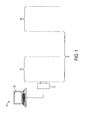
- FIGURE 1 is a diagrammatic illustration showing an exemplary camera system suitable for practicing aspect of the present inventive subject matter.
- FIGURE 2 is a flow chart illustrating an exemplary process for analyzing an image in accordance with aspects of the present inventive subject matter.
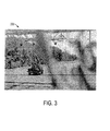
- FIGURE 3 is an illustration showing an exemplary image suitable for analysis in accordance with aspect of the present inventive subject matter.
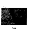
- FIGURE 4 is an illustration showing a resulting edge and/or gradient map generated from the image shown in FIGURE 3 as produced in accordance with aspects of the present inventive subject matter.
- the present specification describes a method, process, apparatus and/or system for detecting a near-field obstruction within a camera's FoV that is reference-image independent, i.e., it does not utilize a reference image for the purpose of such detection.
- the described method, process, apparatus and/or system employs edge detection over an image captured by the camera and computes or otherwise determines or measures a local edge density of the image with an appropriately sized window.
- a region of interest of an image scene is largely in focus under nominal (i.e., not obstructed) conditions. Consequently, the features are sharply captured and exhibit certain homogeneity in edge density or more generally regions with high local gradients.
- an obstruction that is sufficiently near-field compared to the focusing range is generally not in focus. Consequently, the features of the obstruction are blurred and there is a significant reduction in edge density. Accordingly, an image quality metric that reflects the edge density of an observed image is used to detect near-field obstructions, e.g., by comparing a result of the metric to a threshold value.
- the threshold value may be learned from a training set of images with and without near-field obstructions.
- edge generally refers to a location or pixel which exhibits a relatively high local gradient or value difference with respect to a neighboring location or pixel or pixels such as is typically found at the edge of an in-focus object.
- edge as used herein more generally includes any such features exhibiting the foregoing properties, e.g., such as a corner or the like.
- edge detection as used herein more generally includes not only the detection of edges but also the detection of corners and/or other like features exhibiting the foregoing properties and/or the detection of the foregoing properties themselves.
- an automated and/or unattended camera system 10 includes a camera 12 for selectively capturing and/or obtaining an image of a scene within the camera's FoV.
- the camera 12 may be a digital camera and may be either a still picture camera or a video camera.
- a captured or otherwise obtained image from the camera 12 it is intended to mean an image from a picture camera or a still frame from a video camera.
- the camera 12 has an effective focal range FR beginning at some distance D from the camera 12.
- Objects within the FR are generally in focus, while objects outside the FR are generally out of focus.
- In-focus objects or regions in an image captured by the camera 12 will generally appear sharp and/or crisp (e.g., with well-defined edges and/or high local gradients), while out-of-focus object or regions in an image captured by the camera 12 will generally appear blurry and/or fuzzy (e.g., without well-defined edges and/or low local gradients).
- near-field obstructions include but are not limited to: plant growth and/or foliage; ice build-up on the camera lens or porthole; graffiti or debris on the camera lens or porthole; etc.
- the system 10 further includes a computer 30 or the like that is remotely or otherwise in communication with the camera 12.
- the computer 30 obtains or otherwise receives and analyzes images captured by the camera 12 in order to automatically monitor, detect and/or report near-field obstructions.
- the image obtained or received and analyzed by the computer 30 is a digital image, e.g., captured by a digital camera.
- the computer 30 may receive an analog feed which is in turn digitized to obtain a digital image for analysis.
- the computer 30 obtains or receives and analyzes essentially all the images captured by the camera 12.
- the computer 30 may obtain or receive and analyze a representative sample or other subset of the images captured by the camera 12 at periodic or intermittent intervals or otherwise chosen times.
- the images may be transmitted from the camera 12 to the computer 30 and/or analyzed in real time or near real time or in batches or otherwise.
- FIGURE 2 there is shown a flow chart illustrating an exemplary process 100 by which the obtained or captured images are analyzed, e.g., by the computer 30.
- FIGURE 3 shows an exemplary image 200 captured by the camera 12 and that may be so analyzed.
- the image 200 includes a near-field obstruction 202, which in this case is plant foliage.
- the near-field obstruction 202 appears out-of-focus, e.g., as compared to the remainder of the image 200.
- an image is obtained.
- the image 200 may be captured by the camera 12 and transmitted to the computer 30 for analysis.
- edge or gradient detection is applied to the obtained image, e.g., to generate and edge or gradient map 300 such as the one shown in FIGURE 4 .
- the light or white pixels represent edge pixels, i.e., pixels having a high gradient or value difference with respect to neighboring pixels
- the dark or black pixels represent non-edge pixels, i.e., pixels having a low gradient or value difference with respect to neighboring pixels.
- a gradient-base edge detector e.g., such as a Sobel edge detector
- a soft-edge detector e.g., such as a Canny edge detector may be used.
- the latter employs thresholding with hysteresis on the intensity gradient image while tracing edges to enforce edge continuity.
- it may include pixels as edge pixels that are relatively low in local gradient intensity.
- a relatively continuous dark area 302 (e.g., as compared to the remainder of the gradient map 300) corresponds to essentially the same area as the near-field obstruction 202 in the image 200.
- local averaging or similar processing is applied to the edge or gradient map, e.g., to smooth out the spurious nature of edge pixels.
- this is accomplished by defining a local window of suitable size, e.g., centered around a pixel (i,j) of the edge map.
- the window may then be moved or advance over successive pixels in the edge map.
- a binary value is assigned thereto depending upon whether or not an edge pixel resides within the window.
- a value of 1 may be assigned to a pixel (i,j) centered in the window, if an edge pixel resides anywhere in the window, otherwise a value of zero may be assigned to the pixel (i,j) centered in the window, if an edge pixel does not reside anywhere in the window.
- the window may then be moved or advanced to be centered or otherwise placed around the next pixel in the edge map which is in turn likewise assigned a binary value.
- a binary image i.e., a localized edge or gradient density map
- the pixel values represent or indicate a local edge content.
- connected component analysis is applied to the binary image to identify clusters or connected or neighboring groups of pixels therein corresponding to edge-free regions. That is to say, the connected component analysis identifies cluster of pixels having like binary values indicative of edge-free content (e.g., having a binary value of zero in the present example). In this manner, region of significant size in the image are found which lack high frequency content or large gradient changes.
- the edge content is suitably summarized to generate an overall edge or gradient density metric.
- the edge content may be summarized by calculating or otherwise determining a scalar value which measures or otherwise represents the amount of edge-free regions identified by the connected component analysis, e.g., as a percentage of the total image area.
- the metric result (e.g., the generated scalar value) is compared to a set or otherwise determined threshold or threshold condition. If the former does not satisfy the threshold condition (e.g., if the metric result or scalar value is lower than the threshold), then a near-field obstruction may be deemed to have been detected and the process 100 may continue to step 114, otherwise if the former does satisfy the threshold condition (e.g., if the metric result or scalar value meets or exceeds the threshold), then a near-field obstruction may not be deemed to have been detected and the process 100 may end.
- the threshold condition e.g., if the metric result or scalar value is lower than the threshold
- an appropriate threshold may be learned and/or set or determined based upon a statistical analysis of a set of training images obtained with and without near-field obstructions.
- each training image may be subjected to the process 100 or a similar process in order to generate an overall edge or gradient density metric therefor (such as the aforementioned scalar value).
- an overall edge or gradient density metric therefor such as the aforementioned scalar value.
- a suitable notification of the detected near-field obstruction is provided.
- the computer 30 may provide such a notification by way of a visual indication, audible signal, display or sending of a suitable message, activation of a humanly perceivable alert or alarm, etc.
- edge density may not always exhibit suitable homogeneity in region of interest in an image scene.
- sun glare and/or overexposure during daytime may reduce the overall or local edge density.
- certain conditions may optionally be detected before applying the process 100 to an image.
- an image may be subjected to suitable algorithms, processes and/or analysis to detect sun glare and/or overexposure and/or other errors (e.g., which could potentially invalidate the results and/or otherwise interfere with the process 100), and if no such conditions are detected, then analysis in accordance with the process 100 may be executed, otherwise if one or more of such conditions are detected, then execution of the process 100 may be forgone.
- the computer 30 may include a processor, e.g., embodied by a computing or other electronic data processing device, that is configured and/or otherwise provisioned to perform one or more of the tasks, steps, processes, analysis, methods and/or functions described herein.
- a processor e.g., embodied by a computing or other electronic data processing device, that is configured and/or otherwise provisioned to perform one or more of the tasks, steps, processes, analysis, methods and/or functions described herein.
- the computer 30 or other electronic data processing device employed in the system 10 may be provided, supplied and/or programmed with a suitable listing of code (e.g., such as source code, interpretive code, object code, directly executable code, and so forth) or other like instructions or software or firmware (e.g., such as an application to perform and/or administer the processing and/or image analysis described herein), such that when run and/or executed by the computer or other electronic data processing device one or more of the tasks, steps, processes, analysis, methods and/or functions described herein are completed or otherwise performed.
- code e.g., such as source code, interpretive code, object code, directly executable code, and so forth
- firmware e.g., such as an application to perform and/or administer the processing and/or image analysis described herein
- the listing of code or other like instructions or software or firmware is implemented as and/or recorded, stored, contained or included in and/or on a non-transitory computer and/or machine readable storage medium or media so as to be providable to and/or executable by the computer or other electronic data processing device.
- suitable storage mediums and/or media can include but are not limited to: floppy disks, flexible disks, hard disks, magnetic tape, or any other magnetic storage medium or media, CD-ROM, DVD, optical disks, or any other optical medium or media, a RAM, a ROM, a PROM, an EPROM, a FLASH-EPROM, or other memory or chip or cartridge, or any other tangible medium or media from which a computer or machine or electronic data processing device can read and use.
- non-transitory computer-readable and/or machine-readable mediums and/or media comprise all computer-readable and/or machine-readable mediums and/or media except for a transitory, propagating signal.
- any one or more of the particular tasks, steps, processes, analysis, methods, functions, elements and/or components described herein may be implemented on and/or embodiment in one or more general purpose computers, special purpose computer(s), a programmed microprocessor or microcontroller and peripheral integrated circuit elements, an ASIC or other integrated circuit, a digital signal processor, a hardwired electronic or logic circuit such as a discrete element circuit, a programmable logic device such as a PLD, PLA, FPGA, Graphical card CPU (GPU), or PAL, or the like.
- any device capable of implementing a finite state machine that is in turn capable of implementing the respective tasks, steps, processes, analysis, methods and/or functions described herein can be used.
Abstract
Description
- The present inventive subject matter relates generally to the art of automated cameras. Particular but not exclusive relevance is found in connection with red light and/or other traffic cameras. Accordingly, the present specification makes specific reference thereto. It is to be appreciated however that aspects of the present inventive subject matter are also equally amenable to other like applications.
- To capture high quality images with red light, traffic and/or other like automated and/or unattended cameras it is commonly desirable to have an unobstructed field of view (FoV) in which objects of interest may be located. Should the FoV be obstructed, objects of interest, e.g., such as vehicles, drivers and/or license plates, may not be accurately visualized and/or identifiable in images captured by the camera. For example, accurate visualization and/or identification of such objects in captured images are often important for law enforcement purposes and/or the issuing of traffic citation.
- Over time, a camera's FoV may become obstructed by an object in the FoV near the camera. For example, while not initially present, obstructions near the camera may appear due to the growth of plant foliage, ice build-up on the camera lens or porthole, graffiti or debris on the camera lens or porthole, etc. Such obstructions can sufficiently block or obscure various regions sought to be captured in an image obtained by the camera. In turn, one or more objects of interest otherwise sought to be captured in such an image may not be sufficiently visualized and/or readily identifiable in the image. Accordingly, law enforcement or other actions reliant on accurate visualization and/or identification of one or more target objects in a captured image may be frustrated. Moreover, some more advance camera systems may be triggered to capture an image in response to events occurring in a scene observed by the camera, e.g., such as the detection of a vehicle or vehicle movement within the scene. Where such an event is obscured from view by an obstruction, the camera may not capture an otherwise desired image because the event was not detected.
- Traditionally, operators of automated/unattended cameras such as those mentioned above relied on human labor-intensive practices to monitor, check and/or verify obstruction-free operation. For example, an operator may periodically or intermittently conduct a manual review of images obtained from a camera and visually inspect them for obstructions. Such an operator may commonly be assigned a significant number of cameras to check on a fairly frequent basis. Accordingly, such a process can be repetitive and prone to human oversight and/or error. Additionally, a maintenance technician may be assigned to manually inspect camera installations in the field at periodic or intermittent intervals. Again, this is a labor-intensive process prone to human oversight and/or error.
- Alternately, automated methods have been developed to detect camera obstructions from an obtained test image. For example, one such method employs a reference image obtained from an unobstructed camera. In this case, the reference image and test image are subtracted from one another to detect variations therebetween, wherein a detected variation is then deemed indicative of an obstruction in the test image. Such subtractive methods, however, can have certain limitations and/or drawbacks. For example, in dynamically changing scenes, e.g., such as a traffic intersection, objects and/or object locations within the scene may vary from image to image. For example, different vehicles or pedestrians may appear in different images or appear at different locations within different images. Accordingly, by image subtraction from a reference which may not include the same dynamically changing elements, the resulting variations may falsely indicate an obstruction. Additionally, a change in the camera alignment and/or imaging conditions (e.g., such as illumination level) may produce variations in the subtracted image which can again lead to a false indication of an obstruction. Accordingly, such subtraction methods commonly have to account for dynamically varying scenes in order to accurately detect obstructions. The image subtraction and/or aforementioned accounting for dynamically varying scenes can be time intensive and may put further demands and/or complexity on a processor executing the same. Therefore, it has heretofore remained desirable to have an obstruction detection method that is not dependent upon a reference image in this manner.
- Accordingly, a new and/or improved method, system and/or apparatus for monitoring, detecting and/or reporting obstructions in a camera's FoV is disclosed which addresses the above-referenced problem(s) and/or others.
- This summary is provided to introduce concepts related to the present inventive subject matter. This summary is not intended to identify essential features of the claimed subject matter nor is it intended for use in determining or limiting the scope of the claimed subject matter.
- In accordance with one embodiment, a method is provided for detecting an obstruction within a field of view of a camera from an image captured by the camera. The method includes: analyzing the image by applying edge detection to the image, identifying regions of the image lacking edge content and comparing a size of the identified regions to a threshold; and determining if there is an obstruction based upon a result of said comparison.
- In accordance with another embodiment, a method is again provided for detecting an obstruction within a field of view of a camera from an image captured by the camera. The method includes: analyzing the image with a computer processor to identify regions of the image which are out of focus; comparing a size of the identified regions to a threshold; and determining if there is an obstruction based upon a result of said comparison.
- In accordance with still another embodiment, a camera system includes: a camera that obtains an image; and an image processor that analyzes the image to determine if there is an obstruction in the camera's field of view. Suitably, the analyzing includes: applying edge detection to the image; identifying regions of the image lacking edge content; comparing a size of the identified regions to a threshold; and determining if there is an obstruction based upon a result of said comparison.
- Numerous advantages and benefits of the inventive subject matter disclosed herein will become apparent to those of ordinary skill in the art upon reading and understanding the present specification.
- The following detailed description makes reference to the figures in the accompanying drawings. However, the inventive subject matter disclosed herein may take form in various components and arrangements of components, and in various steps and arrangements of steps. The drawings are only for purposes of illustrating exemplary and/or preferred embodiments and are not to be construed as limiting. Further, it is to be appreciated that the drawings may not be to scale.
-
FIGURE 1 is a diagrammatic illustration showing an exemplary camera system suitable for practicing aspect of the present inventive subject matter. -
FIGURE 2 is a flow chart illustrating an exemplary process for analyzing an image in accordance with aspects of the present inventive subject matter. -
FIGURE 3 is an illustration showing an exemplary image suitable for analysis in accordance with aspect of the present inventive subject matter. -
FIGURE 4 is an illustration showing a resulting edge and/or gradient map generated from the image shown inFIGURE 3 as produced in accordance with aspects of the present inventive subject matter. - For clarity and simplicity, the present specification shall refer to structural and/or functional elements, relevant standards and/or protocols, and other components that are commonly known in the art without further detailed explanation as to their configuration or operation except to the extent they have been modified or altered in accordance with and/or to accommodate the preferred embodiment(s) presented herein.
- Generally, the present specification describes a method, process, apparatus and/or system for detecting a near-field obstruction within a camera's FoV that is reference-image independent, i.e., it does not utilize a reference image for the purpose of such detection. In practice, the described method, process, apparatus and/or system employs edge detection over an image captured by the camera and computes or otherwise determines or measures a local edge density of the image with an appropriately sized window. Suitably, a region of interest of an image scene is largely in focus under nominal (i.e., not obstructed) conditions. Consequently, the features are sharply captured and exhibit certain homogeneity in edge density or more generally regions with high local gradients. Conversely, an obstruction that is sufficiently near-field compared to the focusing range is generally not in focus. Consequently, the features of the obstruction are blurred and there is a significant reduction in edge density. Accordingly, an image quality metric that reflects the edge density of an observed image is used to detect near-field obstructions, e.g., by comparing a result of the metric to a threshold value. Suitably, the threshold value may be learned from a training set of images with and without near-field obstructions.
- As used herein, the terms edge generally refers to a location or pixel which exhibits a relatively high local gradient or value difference with respect to a neighboring location or pixel or pixels such as is typically found at the edge of an in-focus object. The term edge as used herein more generally includes any such features exhibiting the foregoing properties, e.g., such as a corner or the like. Additionally, the term edge detection as used herein more generally includes not only the detection of edges but also the detection of corners and/or other like features exhibiting the foregoing properties and/or the detection of the foregoing properties themselves.
- With reference now to
FIGURE 1 , an automated and/orunattended camera system 10 includes acamera 12 for selectively capturing and/or obtaining an image of a scene within the camera's FoV. In practice, thecamera 12 may be a digital camera and may be either a still picture camera or a video camera. When referring herein to a captured or otherwise obtained image from thecamera 12, it is intended to mean an image from a picture camera or a still frame from a video camera. - As shown in
FIGURE 1 , thecamera 12 has an effective focal range FR beginning at some distance D from thecamera 12. Objects within the FR are generally in focus, while objects outside the FR are generally out of focus. In-focus objects or regions in an image captured by thecamera 12 will generally appear sharp and/or crisp (e.g., with well-defined edges and/or high local gradients), while out-of-focus object or regions in an image captured by thecamera 12 will generally appear blurry and/or fuzzy (e.g., without well-defined edges and/or low local gradients). For example, objects and/or regions in the camera's FoV that are sufficiently outside the FR and near thecamera 12, e.g., in a near-field 20 of the camera's FoV, will generally be out-of-focus. Objects in the near-field 20 of the camera's FoV are nominally referred to herein as near-field obstructions. Typical near-field obstructions include but are not limited to: plant growth and/or foliage; ice build-up on the camera lens or porthole; graffiti or debris on the camera lens or porthole; etc. - In the illustrated embodiment, the
system 10 further includes acomputer 30 or the like that is remotely or otherwise in communication with thecamera 12. Suitably, thecomputer 30 obtains or otherwise receives and analyzes images captured by thecamera 12 in order to automatically monitor, detect and/or report near-field obstructions. In practice, the image obtained or received and analyzed by thecomputer 30 is a digital image, e.g., captured by a digital camera. Optionally, thecomputer 30 may receive an analog feed which is in turn digitized to obtain a digital image for analysis. In one suitable embodiment, thecomputer 30 obtains or receives and analyzes essentially all the images captured by thecamera 12. Alternately, thecomputer 30 may obtain or receive and analyze a representative sample or other subset of the images captured by thecamera 12 at periodic or intermittent intervals or otherwise chosen times. Suitably, the images may be transmitted from thecamera 12 to thecomputer 30 and/or analyzed in real time or near real time or in batches or otherwise. - With reference now to
FIGURE 2 , there is shown a flow chart illustrating anexemplary process 100 by which the obtained or captured images are analyzed, e.g., by thecomputer 30. For purposes of the present example, reference is also made toFIGURE 3 which shows anexemplary image 200 captured by thecamera 12 and that may be so analyzed. In particular, theimage 200 includes a near-field obstruction 202, which in this case is plant foliage. Notably, the near-field obstruction 202 appears out-of-focus, e.g., as compared to the remainder of theimage 200. - As shown in
step 102, an image is obtained. For example, theimage 200 may be captured by thecamera 12 and transmitted to thecomputer 30 for analysis. - At
step 104, edge or gradient detection is applied to the obtained image, e.g., to generate and edge orgradient map 300 such as the one shown inFIGURE 4 . As shown, the light or white pixels represent edge pixels, i.e., pixels having a high gradient or value difference with respect to neighboring pixels, and the dark or black pixels represent non-edge pixels, i.e., pixels having a low gradient or value difference with respect to neighboring pixels. Suitably, a gradient-base edge detector, e.g., such as a Sobel edge detector, is employed. Alternately, a soft-edge detector, e.g., such as a Canny edge detector may be used. However, the latter employs thresholding with hysteresis on the intensity gradient image while tracing edges to enforce edge continuity. Thus, it may include pixels as edge pixels that are relatively low in local gradient intensity. Regardless, it is notable in thegradient map 300 that a relatively continuous dark area 302 (e.g., as compared to the remainder of the gradient map 300) corresponds to essentially the same area as the near-field obstruction 202 in theimage 200. - At
step 106, local averaging or similar processing is applied to the edge or gradient map, e.g., to smooth out the spurious nature of edge pixels. Suitably, this is accomplished by defining a local window of suitable size, e.g., centered around a pixel (i,j) of the edge map. In practice, the window may then be moved or advance over successive pixels in the edge map. Suitably, for a given pixel (i,j) around which the window is placed, a binary value is assigned thereto depending upon whether or not an edge pixel resides within the window. For example, a value of 1 may be assigned to a pixel (i,j) centered in the window, if an edge pixel resides anywhere in the window, otherwise a value of zero may be assigned to the pixel (i,j) centered in the window, if an edge pixel does not reside anywhere in the window. The window may then be moved or advanced to be centered or otherwise placed around the next pixel in the edge map which is in turn likewise assigned a binary value. In this manner, a binary image (i.e., a localized edge or gradient density map) may be generated where the pixel values represent or indicate a local edge content. - At
step 108, connected component analysis is applied to the binary image to identify clusters or connected or neighboring groups of pixels therein corresponding to edge-free regions. That is to say, the connected component analysis identifies cluster of pixels having like binary values indicative of edge-free content (e.g., having a binary value of zero in the present example). In this manner, region of significant size in the image are found which lack high frequency content or large gradient changes. - At
step 110, the edge content is suitably summarized to generate an overall edge or gradient density metric. In practice, the edge content may be summarized by calculating or otherwise determining a scalar value which measures or otherwise represents the amount of edge-free regions identified by the connected component analysis, e.g., as a percentage of the total image area. - At
decision step 112, the metric result (e.g., the generated scalar value) is compared to a set or otherwise determined threshold or threshold condition. If the former does not satisfy the threshold condition (e.g., if the metric result or scalar value is lower than the threshold), then a near-field obstruction may be deemed to have been detected and theprocess 100 may continue to step 114, otherwise if the former does satisfy the threshold condition (e.g., if the metric result or scalar value meets or exceeds the threshold), then a near-field obstruction may not be deemed to have been detected and theprocess 100 may end. - In one suitable embodiment, an appropriate threshold may be learned and/or set or determined based upon a statistical analysis of a set of training images obtained with and without near-field obstructions. For example, each training image may be subjected to the
process 100 or a similar process in order to generate an overall edge or gradient density metric therefor (such as the aforementioned scalar value). Accordingly, a nominal distribution of the metrics obtained from the training images may be produced, and based on this distribution, a suitable threshold may be determined or selected. - At
step 114, a suitable notification of the detected near-field obstruction is provided. For example, thecomputer 30 may provide such a notification by way of a visual indication, audible signal, display or sending of a suitable message, activation of a humanly perceivable alert or alarm, etc. - Under certain conditions, edge density may not always exhibit suitable homogeneity in region of interest in an image scene. For example, sun glare and/or overexposure during daytime may reduce the overall or local edge density. Accordingly, certain conditions may optionally be detected before applying the
process 100 to an image. For example, an image may be subjected to suitable algorithms, processes and/or analysis to detect sun glare and/or overexposure and/or other errors (e.g., which could potentially invalidate the results and/or otherwise interfere with the process 100), and if no such conditions are detected, then analysis in accordance with theprocess 100 may be executed, otherwise if one or more of such conditions are detected, then execution of theprocess 100 may be forgone. - The above elements, components, processes, methods, apparatus and/or systems have been described with respect to particular embodiments. It is to be appreciated, however, that certain modifications and/or alteration are also contemplated.
- It is to be appreciated that in connection with the particular exemplary embodiment(s) presented herein certain structural and/or function features are described as being incorporated in defined elements and/or components. However, it is contemplated that these features may, to the same or similar benefit, also likewise be incorporated in other elements and/or components where appropriate. It is also to be appreciated that different aspects of the exemplary embodiments may be selectively employed as appropriate to achieve other alternate embodiments suited for desired applications, the other alternate embodiments thereby realizing the respective advantages of the aspects incorporated therein.
- It is also to be appreciated that any one or more of the particular tasks, steps, processes, analysis, methods, functions, elements and/or components described herein may suitably be implemented via hardware, software, firmware or a combination thereof. For example, the
computer 30 may include a processor, e.g., embodied by a computing or other electronic data processing device, that is configured and/or otherwise provisioned to perform one or more of the tasks, steps, processes, analysis, methods and/or functions described herein. For example, thecomputer 30 or other electronic data processing device employed in thesystem 10 may be provided, supplied and/or programmed with a suitable listing of code (e.g., such as source code, interpretive code, object code, directly executable code, and so forth) or other like instructions or software or firmware (e.g., such as an application to perform and/or administer the processing and/or image analysis described herein), such that when run and/or executed by the computer or other electronic data processing device one or more of the tasks, steps, processes, analysis, methods and/or functions described herein are completed or otherwise performed. Suitably, the listing of code or other like instructions or software or firmware is implemented as and/or recorded, stored, contained or included in and/or on a non-transitory computer and/or machine readable storage medium or media so as to be providable to and/or executable by the computer or other electronic data processing device. For example, suitable storage mediums and/or media can include but are not limited to: floppy disks, flexible disks, hard disks, magnetic tape, or any other magnetic storage medium or media, CD-ROM, DVD, optical disks, or any other optical medium or media, a RAM, a ROM, a PROM, an EPROM, a FLASH-EPROM, or other memory or chip or cartridge, or any other tangible medium or media from which a computer or machine or electronic data processing device can read and use. In essence, as used herein, non-transitory computer-readable and/or machine-readable mediums and/or media comprise all computer-readable and/or machine-readable mediums and/or media except for a transitory, propagating signal. - Optionally, any one or more of the particular tasks, steps, processes, analysis, methods, functions, elements and/or components described herein may be implemented on and/or embodiment in one or more general purpose computers, special purpose computer(s), a programmed microprocessor or microcontroller and peripheral integrated circuit elements, an ASIC or other integrated circuit, a digital signal processor, a hardwired electronic or logic circuit such as a discrete element circuit, a programmable logic device such as a PLD, PLA, FPGA, Graphical card CPU (GPU), or PAL, or the like. In general, any device, capable of implementing a finite state machine that is in turn capable of implementing the respective tasks, steps, processes, analysis, methods and/or functions described herein can be used.
Claims (15)
- A method for detecting an obstruction within a field of view of a camera from an image captured by the camera, said method comprising:analyzing the image, said analyzing of the image comprising:applying edge detection to the image;identifying regions of the image lacking edge content; and,comparing a size of the identified regions to a threshold; anddetermining if there is an obstruction based upon a result of said comparison.
- The method of claim 1, wherein applying said edge detection generates an edge map including a plurality of pixels, where each pixel may be either an edge pixel or not an edge pixel, and said analyzing further comprises:local smoothing of said map.
- The method of claim 2, wherein said local smoothing comprises:placing a window around a given pixel of the map;assigning a value associated with the given pixel based upon whether or not any pixel within the window is an edge pixel; andrepeating said placing and said assigning for successive pixels of the map.
- The method of claim 2 or claim 3, wherein said identifying comprises:performing connected component analysis on the smoothed map.
- The method of any of the preceding claims, wherein said analyzing further comprising:generating a scalar value which represents the size of the identified regions.
- The method of claim 5, wherein the scalar value is a percentage relative to an entire area of the image.
- The method of any of the preceding claims, wherein said threshold is selected based on a statistical analysis of a set of training images including at least one image obtained by a camera with an obstruction in its field of view and at least one image obtained by a camera without an obstruction in its field of view.
- The method of any of the preceding claims, said method further comprising:providing notification of a detected obstruction.
- An apparatus that executes the method of any of the preceding claims.
- A non-transitory machine-readable medium including a computer program which when executed performs the method of any of claims 1 to 8.
- A method for detecting an obstruction within a field of view of a camera from an image captured by the camera, said method comprising:analyzing the image with a computer processor to identify regions of the image which are out of focus;comparing a size of the identified regions to a threshold; anddetermining if there is an obstruction based upon a result of said comparison.
- A camera system comprising:a camera that obtains an image; andan image processor that analyzes said image to determine if there is an obstruction in the camera's field of view, wherein said analyzing includes:applying edge detection to the image;identifying regions of the image lacking edge content;comparing a size of the identified regions to a threshold; anddetermining if there is an obstruction based upon a result of said comparison.
- The camera system of claim 12, wherein applying said edge detection generates an edge map including a plurality of pixels, where each pixel may be either an edge pixel or not an edge pixel, and said analyzing further comprises:local smoothing of said map.
- The camera system of claim 13, wherein said local smoothing comprises:placing a window around a given pixel of the map;assigning a value associated with the given pixel based upon whether or not any pixel within the window is an edge pixel; andrepeating said placing and said assigning for successive pixels of the map.
- The camera system of claim 13 or claim 14, wherein said identifying comprises:performing connected component analysis on the smoothed map.
Applications Claiming Priority (1)
| Application Number | Priority Date | Filing Date | Title |
|---|---|---|---|
| US13/472,126 US9064317B2 (en) | 2012-05-15 | 2012-05-15 | Detection of near-field camera obstruction |
Publications (3)
| Publication Number | Publication Date |
|---|---|
| EP2665039A2 true EP2665039A2 (en) | 2013-11-20 |
| EP2665039A3 EP2665039A3 (en) | 2015-04-29 |
| EP2665039B1 EP2665039B1 (en) | 2017-03-08 |
Family
ID=48740804
Family Applications (1)
| Application Number | Title | Priority Date | Filing Date |
|---|---|---|---|
| EP13167880.7A Active EP2665039B1 (en) | 2012-05-15 | 2013-05-15 | Detection of near-field camera obstruction |
Country Status (3)
| Country | Link |
|---|---|
| US (1) | US9064317B2 (en) |
| EP (1) | EP2665039B1 (en) |
| JP (1) | JP6205172B2 (en) |
Cited By (1)
| Publication number | Priority date | Publication date | Assignee | Title |
|---|---|---|---|---|
| WO2018039925A1 (en) | 2016-08-30 | 2018-03-08 | SZ DJI Technology Co., Ltd. | Method and system for detecting obstructive object at projected locations within images |
Families Citing this family (10)
| Publication number | Priority date | Publication date | Assignee | Title |
|---|---|---|---|---|
| WO2014007175A1 (en) * | 2012-07-03 | 2014-01-09 | クラリオン株式会社 | Vehicle-mounted environment recognition device |
| US10339812B2 (en) | 2017-03-02 | 2019-07-02 | Denso International America, Inc. | Surrounding view camera blockage detection |
| US10547801B2 (en) * | 2017-10-26 | 2020-01-28 | International Business Machines Corporation | Detecting an image obstruction |
| US11087487B2 (en) | 2018-10-25 | 2021-08-10 | Northrop Grumman Systems Corporation | Obscuration map generation |
| US11328428B2 (en) * | 2019-12-18 | 2022-05-10 | Clarion Co., Ltd. | Technologies for detection of occlusions on a camera |
| JP7319597B2 (en) * | 2020-09-23 | 2023-08-02 | トヨタ自動車株式会社 | Vehicle driving support device |
| US11716531B2 (en) | 2021-03-22 | 2023-08-01 | International Business Machines Corporation | Quality of multimedia |
| US11533427B2 (en) | 2021-03-22 | 2022-12-20 | International Business Machines Corporation | Multimedia quality evaluation |
| US11483472B2 (en) | 2021-03-22 | 2022-10-25 | International Business Machines Corporation | Enhancing quality of multimedia |
| DE102021213269A1 (en) | 2021-11-25 | 2023-05-25 | Zf Friedrichshafen Ag | Machine learning model, method, computer program and fail-safe system for safe image processing when detecting local and/or global image defects and/or internal defects of at least one imaging sensor of a vehicle perception system and driving system that can be operated automatically |
Family Cites Families (14)
| Publication number | Priority date | Publication date | Assignee | Title |
|---|---|---|---|---|
| JPH05282593A (en) * | 1992-04-02 | 1993-10-29 | Sumitomo Electric Ind Ltd | Vehicle head detecting device |
| US5621645A (en) * | 1995-01-24 | 1997-04-15 | Minnesota Mining And Manufacturing Company | Automated lane definition for machine vision traffic detector |
| JPH11110564A (en) * | 1997-09-30 | 1999-04-23 | Mitsubishi Heavy Ind Ltd | Moving body measuring device |
| JP3516127B2 (en) * | 1997-12-09 | 2004-04-05 | オムロン株式会社 | Image processing method and apparatus |
| JPH11261993A (en) * | 1998-03-06 | 1999-09-24 | Omron Corp | Deviation detecting method for image pickup device and image processor using the same method |
| JP2004310282A (en) * | 2003-04-03 | 2004-11-04 | Nissan Motor Co Ltd | Vehicle detector |
| US7196305B2 (en) * | 2005-01-18 | 2007-03-27 | Ford Global Technologies, Llc | Vehicle imaging processing system and method having obstructed image detection |
| US8553088B2 (en) * | 2005-11-23 | 2013-10-08 | Mobileye Technologies Limited | Systems and methods for detecting obstructions in a camera field of view |
| EP2026281A1 (en) * | 2006-05-25 | 2009-02-18 | NEC Corporation | Recognizing system, recognizing metho and recognizing program |
| US7711193B2 (en) * | 2006-11-07 | 2010-05-04 | Aol Inc. | Recognizing blank and nearly blank images |
| EP1936576B1 (en) | 2006-12-20 | 2011-08-17 | Axis AB | Camera tampering detection |
| JP5356728B2 (en) * | 2008-05-26 | 2013-12-04 | 株式会社トプコン | Edge extraction device, surveying instrument, and program |
| JP5372680B2 (en) * | 2009-09-24 | 2013-12-18 | 日立オートモティブシステムズ株式会社 | Obstacle detection device |
| US8548256B2 (en) * | 2010-07-01 | 2013-10-01 | Intellectual Ventures Fund 83 Llc | Method for fast scene matching |
-
2012
- 2012-05-15 US US13/472,126 patent/US9064317B2/en active Active
-
2013
- 2013-05-01 JP JP2013096134A patent/JP6205172B2/en active Active
- 2013-05-15 EP EP13167880.7A patent/EP2665039B1/en active Active
Non-Patent Citations (1)
| Title |
|---|
| None |
Cited By (4)
| Publication number | Priority date | Publication date | Assignee | Title |
|---|---|---|---|---|
| WO2018039925A1 (en) | 2016-08-30 | 2018-03-08 | SZ DJI Technology Co., Ltd. | Method and system for detecting obstructive object at projected locations within images |
| EP3371679A4 (en) * | 2016-08-30 | 2018-12-05 | SZ DJI Technology Co., Ltd. | Method and system for detecting obstructive object at projected locations within images |
| US10853969B2 (en) | 2016-08-30 | 2020-12-01 | SZ DJI Technology Co., Ltd. | Method and system for detecting obstructive object at projected locations within images |
| CN109074199B (en) * | 2016-08-30 | 2021-12-28 | 深圳市大疆创新科技有限公司 | Method and system for detecting obstacles at a projection position within an image |
Also Published As
| Publication number | Publication date |
|---|---|
| US9064317B2 (en) | 2015-06-23 |
| EP2665039A3 (en) | 2015-04-29 |
| EP2665039B1 (en) | 2017-03-08 |
| US20130308004A1 (en) | 2013-11-21 |
| JP2013239165A (en) | 2013-11-28 |
| JP6205172B2 (en) | 2017-09-27 |
Similar Documents
| Publication | Publication Date | Title |
|---|---|---|
| EP2665039B1 (en) | Detection of near-field camera obstruction | |
| EP3149656B1 (en) | Detection, identification, and mitigation of lens contamination for vehicle mounted camera systems | |
| JP5241782B2 (en) | Surveillance camera system having a camera abnormality detection device | |
| EP2821960B1 (en) | Method for identification of contamination upon a lens of a stereoscopic camera | |
| US9030559B2 (en) | Constrained parametric curve detection using clustering on Hough curves over a sequence of images | |
| US20130335579A1 (en) | Detection of camera misalignment | |
| JP2013065304A (en) | High-speed obstacle detection | |
| CN111783744A (en) | Operation site safety protection detection method and device | |
| US10692225B2 (en) | System and method for detecting moving object in an image | |
| JP5087112B2 (en) | Self-monitoring camera device | |
| JP2012185684A (en) | Object detection device and object detection method | |
| US10115028B2 (en) | Method and device for classifying an object in an image | |
| WO2012081969A1 (en) | A system and method to detect intrusion event | |
| US9536165B2 (en) | Flash characterization for camera | |
| JP4765113B2 (en) | Vehicle periphery monitoring device, vehicle, vehicle periphery monitoring program, and vehicle periphery monitoring method | |
| CN110020572B (en) | People counting method, device and equipment based on video image and storage medium | |
| JP2009193390A (en) | Vehicle periphery monitor device, vehicle, and program and method for monitoring vehicle periphery | |
| KR101951900B1 (en) | Method and Apparatus for Detecting Object in an Image | |
| JP6114559B2 (en) | Automatic unevenness detector for flat panel display | |
| CN107680118B (en) | Image identification tracking method | |
| CN113763311A (en) | Image recognition method and device and automatic sorting robot | |
| TWI599222B (en) | Photographic device anomaly detection method | |
| JP2009140160A (en) | Vehicle number reader | |
| JP2015097089A (en) | Object detection device and object detection method | |
| CN115082571B (en) | Anomaly detection method and system for in-road parking camera |
Legal Events
| Date | Code | Title | Description |
|---|---|---|---|
| PUAI | Public reference made under article 153(3) epc to a published international application that has entered the european phase |
Free format text: ORIGINAL CODE: 0009012 |
|
| AK | Designated contracting states |
Kind code of ref document: A2 Designated state(s): AL AT BE BG CH CY CZ DE DK EE ES FI FR GB GR HR HU IE IS IT LI LT LU LV MC MK MT NL NO PL PT RO RS SE SI SK SM TR |
|
| AX | Request for extension of the european patent |
Extension state: BA ME |
|
| PUAL | Search report despatched |
Free format text: ORIGINAL CODE: 0009013 |
|
| AK | Designated contracting states |
Kind code of ref document: A3 Designated state(s): AL AT BE BG CH CY CZ DE DK EE ES FI FR GB GR HR HU IE IS IT LI LT LU LV MC MK MT NL NO PL PT RO RS SE SI SK SM TR |
|
| AX | Request for extension of the european patent |
Extension state: BA ME |
|
| RIC1 | Information provided on ipc code assigned before grant |
Ipc: G06T 7/00 20060101AFI20150326BHEP |
|
| 17P | Request for examination filed |
Effective date: 20151006 |
|
| RBV | Designated contracting states (corrected) |
Designated state(s): AL AT BE BG CH CY CZ DE DK EE ES FI FR GB GR HR HU IE IS IT LI LT LU LV MC MK MT NL NO PL PT RO RS SE SI SK SM TR |
|
| 17Q | First examination report despatched |
Effective date: 20160121 |
|
| GRAP | Despatch of communication of intention to grant a patent |
Free format text: ORIGINAL CODE: EPIDOSNIGR1 |
|
| INTG | Intention to grant announced |
Effective date: 20160920 |
|
| GRAS | Grant fee paid |
Free format text: ORIGINAL CODE: EPIDOSNIGR3 |
|
| GRAA | (expected) grant |
Free format text: ORIGINAL CODE: 0009210 |
|
| AK | Designated contracting states |
Kind code of ref document: B1 Designated state(s): AL AT BE BG CH CY CZ DE DK EE ES FI FR GB GR HR HU IE IS IT LI LT LU LV MC MK MT NL NO PL PT RO RS SE SI SK SM TR |
|
| REG | Reference to a national code |
Ref country code: GB Ref legal event code: FG4D |
|
| REG | Reference to a national code |
Ref country code: CH Ref legal event code: EP Ref country code: AT Ref legal event code: REF Ref document number: 874140 Country of ref document: AT Kind code of ref document: T Effective date: 20170315 |
|
| REG | Reference to a national code |
Ref country code: IE Ref legal event code: FG4D |
|
| REG | Reference to a national code |
Ref country code: DE Ref legal event code: R096 Ref document number: 602013018196 Country of ref document: DE |
|
| REG | Reference to a national code |
Ref country code: FR Ref legal event code: PLFP Year of fee payment: 5 |
|
| REG | Reference to a national code |
Ref country code: LT Ref legal event code: MG4D |
|
| REG | Reference to a national code |
Ref country code: NL Ref legal event code: MP Effective date: 20170308 |
|
| PG25 | Lapsed in a contracting state [announced via postgrant information from national office to epo] |
Ref country code: FI Free format text: LAPSE BECAUSE OF FAILURE TO SUBMIT A TRANSLATION OF THE DESCRIPTION OR TO PAY THE FEE WITHIN THE PRESCRIBED TIME-LIMIT Effective date: 20170308 Ref country code: HR Free format text: LAPSE BECAUSE OF FAILURE TO SUBMIT A TRANSLATION OF THE DESCRIPTION OR TO PAY THE FEE WITHIN THE PRESCRIBED TIME-LIMIT Effective date: 20170308 Ref country code: NO Free format text: LAPSE BECAUSE OF FAILURE TO SUBMIT A TRANSLATION OF THE DESCRIPTION OR TO PAY THE FEE WITHIN THE PRESCRIBED TIME-LIMIT Effective date: 20170608 Ref country code: GR Free format text: LAPSE BECAUSE OF FAILURE TO SUBMIT A TRANSLATION OF THE DESCRIPTION OR TO PAY THE FEE WITHIN THE PRESCRIBED TIME-LIMIT Effective date: 20170609 Ref country code: LT Free format text: LAPSE BECAUSE OF FAILURE TO SUBMIT A TRANSLATION OF THE DESCRIPTION OR TO PAY THE FEE WITHIN THE PRESCRIBED TIME-LIMIT Effective date: 20170308 |
|
| REG | Reference to a national code |
Ref country code: AT Ref legal event code: MK05 Ref document number: 874140 Country of ref document: AT Kind code of ref document: T Effective date: 20170308 |
|
| PG25 | Lapsed in a contracting state [announced via postgrant information from national office to epo] |
Ref country code: LV Free format text: LAPSE BECAUSE OF FAILURE TO SUBMIT A TRANSLATION OF THE DESCRIPTION OR TO PAY THE FEE WITHIN THE PRESCRIBED TIME-LIMIT Effective date: 20170308 Ref country code: ES Free format text: LAPSE BECAUSE OF FAILURE TO SUBMIT A TRANSLATION OF THE DESCRIPTION OR TO PAY THE FEE WITHIN THE PRESCRIBED TIME-LIMIT Effective date: 20170308 Ref country code: BG Free format text: LAPSE BECAUSE OF FAILURE TO SUBMIT A TRANSLATION OF THE DESCRIPTION OR TO PAY THE FEE WITHIN THE PRESCRIBED TIME-LIMIT Effective date: 20170608 Ref country code: RS Free format text: LAPSE BECAUSE OF FAILURE TO SUBMIT A TRANSLATION OF THE DESCRIPTION OR TO PAY THE FEE WITHIN THE PRESCRIBED TIME-LIMIT Effective date: 20170308 Ref country code: LU Free format text: LAPSE BECAUSE OF NON-PAYMENT OF DUE FEES Effective date: 20170531 Ref country code: SE Free format text: LAPSE BECAUSE OF FAILURE TO SUBMIT A TRANSLATION OF THE DESCRIPTION OR TO PAY THE FEE WITHIN THE PRESCRIBED TIME-LIMIT Effective date: 20170308 |
|
| PG25 | Lapsed in a contracting state [announced via postgrant information from national office to epo] |
Ref country code: NL Free format text: LAPSE BECAUSE OF FAILURE TO SUBMIT A TRANSLATION OF THE DESCRIPTION OR TO PAY THE FEE WITHIN THE PRESCRIBED TIME-LIMIT Effective date: 20170308 |
|
| PG25 | Lapsed in a contracting state [announced via postgrant information from national office to epo] |
Ref country code: AT Free format text: LAPSE BECAUSE OF FAILURE TO SUBMIT A TRANSLATION OF THE DESCRIPTION OR TO PAY THE FEE WITHIN THE PRESCRIBED TIME-LIMIT Effective date: 20170308 Ref country code: CZ Free format text: LAPSE BECAUSE OF FAILURE TO SUBMIT A TRANSLATION OF THE DESCRIPTION OR TO PAY THE FEE WITHIN THE PRESCRIBED TIME-LIMIT Effective date: 20170308 Ref country code: IT Free format text: LAPSE BECAUSE OF FAILURE TO SUBMIT A TRANSLATION OF THE DESCRIPTION OR TO PAY THE FEE WITHIN THE PRESCRIBED TIME-LIMIT Effective date: 20170308 Ref country code: EE Free format text: LAPSE BECAUSE OF FAILURE TO SUBMIT A TRANSLATION OF THE DESCRIPTION OR TO PAY THE FEE WITHIN THE PRESCRIBED TIME-LIMIT Effective date: 20170308 Ref country code: SK Free format text: LAPSE BECAUSE OF FAILURE TO SUBMIT A TRANSLATION OF THE DESCRIPTION OR TO PAY THE FEE WITHIN THE PRESCRIBED TIME-LIMIT Effective date: 20170308 Ref country code: RO Free format text: LAPSE BECAUSE OF FAILURE TO SUBMIT A TRANSLATION OF THE DESCRIPTION OR TO PAY THE FEE WITHIN THE PRESCRIBED TIME-LIMIT Effective date: 20170308 |
|
| PG25 | Lapsed in a contracting state [announced via postgrant information from national office to epo] |
Ref country code: PT Free format text: LAPSE BECAUSE OF FAILURE TO SUBMIT A TRANSLATION OF THE DESCRIPTION OR TO PAY THE FEE WITHIN THE PRESCRIBED TIME-LIMIT Effective date: 20170710 Ref country code: PL Free format text: LAPSE BECAUSE OF FAILURE TO SUBMIT A TRANSLATION OF THE DESCRIPTION OR TO PAY THE FEE WITHIN THE PRESCRIBED TIME-LIMIT Effective date: 20170308 Ref country code: SM Free format text: LAPSE BECAUSE OF FAILURE TO SUBMIT A TRANSLATION OF THE DESCRIPTION OR TO PAY THE FEE WITHIN THE PRESCRIBED TIME-LIMIT Effective date: 20170308 Ref country code: IS Free format text: LAPSE BECAUSE OF FAILURE TO SUBMIT A TRANSLATION OF THE DESCRIPTION OR TO PAY THE FEE WITHIN THE PRESCRIBED TIME-LIMIT Effective date: 20170708 |
|
| REG | Reference to a national code |
Ref country code: DE Ref legal event code: R097 Ref document number: 602013018196 Country of ref document: DE |
|
| REG | Reference to a national code |
Ref country code: CH Ref legal event code: PL |
|
| PLBE | No opposition filed within time limit |
Free format text: ORIGINAL CODE: 0009261 |
|
| STAA | Information on the status of an ep patent application or granted ep patent |
Free format text: STATUS: NO OPPOSITION FILED WITHIN TIME LIMIT |
|
| PG25 | Lapsed in a contracting state [announced via postgrant information from national office to epo] |
Ref country code: MC Free format text: LAPSE BECAUSE OF FAILURE TO SUBMIT A TRANSLATION OF THE DESCRIPTION OR TO PAY THE FEE WITHIN THE PRESCRIBED TIME-LIMIT Effective date: 20170308 Ref country code: DK Free format text: LAPSE BECAUSE OF FAILURE TO SUBMIT A TRANSLATION OF THE DESCRIPTION OR TO PAY THE FEE WITHIN THE PRESCRIBED TIME-LIMIT Effective date: 20170308 |
|
| 26N | No opposition filed |
Effective date: 20171211 |
|
| REG | Reference to a national code |
Ref country code: IE Ref legal event code: MM4A |
|
| PG25 | Lapsed in a contracting state [announced via postgrant information from national office to epo] |
Ref country code: CH Free format text: LAPSE BECAUSE OF NON-PAYMENT OF DUE FEES Effective date: 20170531 Ref country code: LI Free format text: LAPSE BECAUSE OF NON-PAYMENT OF DUE FEES Effective date: 20170531 Ref country code: SI Free format text: LAPSE BECAUSE OF FAILURE TO SUBMIT A TRANSLATION OF THE DESCRIPTION OR TO PAY THE FEE WITHIN THE PRESCRIBED TIME-LIMIT Effective date: 20170308 |
|
| PG25 | Lapsed in a contracting state [announced via postgrant information from national office to epo] |
Ref country code: LU Free format text: LAPSE BECAUSE OF NON-PAYMENT OF DUE FEES Effective date: 20170515 |
|
| REG | Reference to a national code |
Ref country code: FR Ref legal event code: PLFP Year of fee payment: 6 |
|
| REG | Reference to a national code |
Ref country code: BE Ref legal event code: MM Effective date: 20170531 |
|
| PG25 | Lapsed in a contracting state [announced via postgrant information from national office to epo] |
Ref country code: IE Free format text: LAPSE BECAUSE OF NON-PAYMENT OF DUE FEES Effective date: 20170515 |
|
| PG25 | Lapsed in a contracting state [announced via postgrant information from national office to epo] |
Ref country code: BE Free format text: LAPSE BECAUSE OF NON-PAYMENT OF DUE FEES Effective date: 20170531 |
|
| PG25 | Lapsed in a contracting state [announced via postgrant information from national office to epo] |
Ref country code: MT Free format text: LAPSE BECAUSE OF NON-PAYMENT OF DUE FEES Effective date: 20170515 |
|
| PG25 | Lapsed in a contracting state [announced via postgrant information from national office to epo] |
Ref country code: HU Free format text: LAPSE BECAUSE OF FAILURE TO SUBMIT A TRANSLATION OF THE DESCRIPTION OR TO PAY THE FEE WITHIN THE PRESCRIBED TIME-LIMIT; INVALID AB INITIO Effective date: 20130515 |
|
| PG25 | Lapsed in a contracting state [announced via postgrant information from national office to epo] |
Ref country code: CY Free format text: LAPSE BECAUSE OF NON-PAYMENT OF DUE FEES Effective date: 20170308 |
|
| PG25 | Lapsed in a contracting state [announced via postgrant information from national office to epo] |
Ref country code: MK Free format text: LAPSE BECAUSE OF FAILURE TO SUBMIT A TRANSLATION OF THE DESCRIPTION OR TO PAY THE FEE WITHIN THE PRESCRIBED TIME-LIMIT Effective date: 20170308 |
|
| PG25 | Lapsed in a contracting state [announced via postgrant information from national office to epo] |
Ref country code: TR Free format text: LAPSE BECAUSE OF FAILURE TO SUBMIT A TRANSLATION OF THE DESCRIPTION OR TO PAY THE FEE WITHIN THE PRESCRIBED TIME-LIMIT Effective date: 20170308 |
|
| PG25 | Lapsed in a contracting state [announced via postgrant information from national office to epo] |
Ref country code: AL Free format text: LAPSE BECAUSE OF FAILURE TO SUBMIT A TRANSLATION OF THE DESCRIPTION OR TO PAY THE FEE WITHIN THE PRESCRIBED TIME-LIMIT Effective date: 20170308 |
|
| PGFP | Annual fee paid to national office [announced via postgrant information from national office to epo] |
Ref country code: FR Payment date: 20230420 Year of fee payment: 11 Ref country code: DE Payment date: 20230419 Year of fee payment: 11 |
|
| PGFP | Annual fee paid to national office [announced via postgrant information from national office to epo] |
Ref country code: GB Payment date: 20230420 Year of fee payment: 11 |