EP3371494B1 - Tanksicherungsarmatur und tank - Google Patents
Tanksicherungsarmatur und tank Download PDFInfo
- Publication number
- EP3371494B1 EP3371494B1 EP16781098.5A EP16781098A EP3371494B1 EP 3371494 B1 EP3371494 B1 EP 3371494B1 EP 16781098 A EP16781098 A EP 16781098A EP 3371494 B1 EP3371494 B1 EP 3371494B1
- Authority
- EP
- European Patent Office
- Prior art keywords
- tank
- valve
- housing
- ring flange
- tank protection
- Prior art date
- Legal status (The legal status is an assumption and is not a legal conclusion. Google has not performed a legal analysis and makes no representation as to the accuracy of the status listed.)
- Active
Links
Images




Classifications
-
- F—MECHANICAL ENGINEERING; LIGHTING; HEATING; WEAPONS; BLASTING
- F16—ENGINEERING ELEMENTS AND UNITS; GENERAL MEASURES FOR PRODUCING AND MAINTAINING EFFECTIVE FUNCTIONING OF MACHINES OR INSTALLATIONS; THERMAL INSULATION IN GENERAL
- F16K—VALVES; TAPS; COCKS; ACTUATING-FLOATS; DEVICES FOR VENTING OR AERATING
- F16K24/00—Devices, e.g. valves, for venting or aerating enclosures
-
- F—MECHANICAL ENGINEERING; LIGHTING; HEATING; WEAPONS; BLASTING
- F16—ENGINEERING ELEMENTS AND UNITS; GENERAL MEASURES FOR PRODUCING AND MAINTAINING EFFECTIVE FUNCTIONING OF MACHINES OR INSTALLATIONS; THERMAL INSULATION IN GENERAL
- F16K—VALVES; TAPS; COCKS; ACTUATING-FLOATS; DEVICES FOR VENTING OR AERATING
- F16K24/00—Devices, e.g. valves, for venting or aerating enclosures
- F16K24/06—Devices, e.g. valves, for venting or aerating enclosures for aerating only
-
- F—MECHANICAL ENGINEERING; LIGHTING; HEATING; WEAPONS; BLASTING
- F16—ENGINEERING ELEMENTS AND UNITS; GENERAL MEASURES FOR PRODUCING AND MAINTAINING EFFECTIVE FUNCTIONING OF MACHINES OR INSTALLATIONS; THERMAL INSULATION IN GENERAL
- F16K—VALVES; TAPS; COCKS; ACTUATING-FLOATS; DEVICES FOR VENTING OR AERATING
- F16K27/00—Construction of housing; Use of materials therefor
- F16K27/02—Construction of housing; Use of materials therefor of lift valves
-
- F—MECHANICAL ENGINEERING; LIGHTING; HEATING; WEAPONS; BLASTING
- F16—ENGINEERING ELEMENTS AND UNITS; GENERAL MEASURES FOR PRODUCING AND MAINTAINING EFFECTIVE FUNCTIONING OF MACHINES OR INSTALLATIONS; THERMAL INSULATION IN GENERAL
- F16K—VALVES; TAPS; COCKS; ACTUATING-FLOATS; DEVICES FOR VENTING OR AERATING
- F16K31/00—Actuating devices; Operating means; Releasing devices
- F16K31/12—Actuating devices; Operating means; Releasing devices actuated by fluid
- F16K31/14—Actuating devices; Operating means; Releasing devices actuated by fluid for mounting on, or in combination with, hand-actuated valves
- F16K31/143—Actuating devices; Operating means; Releasing devices actuated by fluid for mounting on, or in combination with, hand-actuated valves the fluid acting on a piston
-
- B—PERFORMING OPERATIONS; TRANSPORTING
- B65—CONVEYING; PACKING; STORING; HANDLING THIN OR FILAMENTARY MATERIAL
- B65D—CONTAINERS FOR STORAGE OR TRANSPORT OF ARTICLES OR MATERIALS, e.g. BAGS, BARRELS, BOTTLES, BOXES, CANS, CARTONS, CRATES, DRUMS, JARS, TANKS, HOPPERS, FORWARDING CONTAINERS; ACCESSORIES, CLOSURES, OR FITTINGS THEREFOR; PACKAGING ELEMENTS; PACKAGES
- B65D90/00—Component parts, details or accessories for large containers
- B65D90/22—Safety features
- B65D90/32—Arrangements for preventing, or minimising the effect of, excessive or insufficient pressure
- B65D90/34—Venting means
Definitions
- the invention relates to a tank safety fitting according to the preamble of claim 1 and a tank according to claim 11.
- tanks with a volume of up to 800 m 3 are used, for example in beverage bottling plants, which have only limited resistance to negative pressure.
- Reasons for the occurrence of a negative pressure are, for example, a system drainage by means of a pump, an unintended emptying of the system, or physical state changes of the stored medium and / or fermentation processes, and the like.
- a permissible negative pressure in such tanks is often only 10 mbar.
- vacuum valves in different sizes used which have a set pressure of only 3 to 4 mbar and have a correspondingly high volume flow rate.
- the mandatory vertical installation of the vacuum valve is disadvantageous.
- the tank safety valve has a cross piece with a central connection, the vacuum valve requires a separate corner housing, which requires additional costs, is less easy to clean and increases the space requirement.
- a tank lid is needed in which vacuum valves are installed. This also increases the cost and requires more effort, since under certain circumstances separate cleaning nozzles are required with appropriate piping.
- a tank faucet which comprises a weight-loaded pressure relief valve with a protective cap turned up and a flap vacuum valve with weight load.
- the valve plate of the vacuum valve is guided in the swinging opening movement in a lateral hinge.
- the weight load is threaded onto a valve rod of the valve disk.
- a spring preload can be used instead of a weight load.
- the vacuum valve is installed vertically.
- the invention has for its object to provide a vacuum valve in which regardless of the installation position in a cleaning cycle cleaning medium safely collected and effectively removes cleaning medium entrained even when the tank is blown off, and to provide a tank with improved performance characteristics.
- the annular flange causes e.g. when blowing off the tank escaping air-cleaning medium mixture is passed around the annular flange on the back. The centrifugal forces generated by the strong deflection divorced from the mixture contained in the drip tray. Drops hitting the back of the annular flange will stick there and run down under gravity until eventually they are directed through the radial rib into the drip tray. From the drip tray collected cleaning medium is disposed of via the discharge channel targeted.
- the vacuum valve can also be installed vertically, but then without closing spring, the proper response of the vacuum valve, for example, at about 3 mbar is ensured by the lightweight construction of the valve plate assembly and the weight and the catch structure cleaning medium during the cleaning cycle and blowing off the tank safely collects and dissipates.
- the vacuum valve With horizontal installation of the vacuum valve no dead space is created at a crosspiece of the tank fuse fitting, which offers significant advantages in the cleaning, since the sealing seat sits directly opposite the cleaning line or nozzles in the crosspiece and is thoroughly cleaned. Because of the cost-effective design of the vacuum valve and its small footprint on a cross piece can be installed to increase the throughput multiple, even redundant vacuum valves.
- the tank has an improved operating behavior with the tank safety valve, since contamination is avoided when cleaning the vacuum valve.
- the outer wall region of the drip pan enclosing the annular flange has a C-shaped cross-section with a shell edge bent in the direction of the annular flange. This concept reliably brings cleaning medium into the drip tray.
- the annular flange has a cone opening angle between about 180 ° and 120 °, preferably about 130 °. This tendency promotes the leadership of the currents and the deposition of liquid portions of the cleaning medium.
- the broadening may be bent away from the shell rim in the direction of the annular flange, e.g. with concave inside to increase the catching effect.
- the radial rib uses the adhesion tendency of the liquid cleaning medium to collect this under the influence of gravity and centrifugal force and to guide it into the drip tray.
- the physical interaction between the annular flange, the inwardly curved shell edge and the radial rib results in an excellent separation effect for the cleaning medium.
- the optionally provided circumferential groove in the housing defines a boundary line beyond which the cleaning medium does not reach or is collected in the cleaning medium and guided under gravity to the radial rib.
- the radial rib has a rounded beginning, approximately constant wall thickness and gradually increasing height in the direction of the bottom of the drip tray, either with a substantially straight slightly sloping or concave curved entering the annular flange comb.
- the vacuum valve is installed with substantially horizontal valve stem, a closing spring and a bottom, substantially horizontally discharging discharge channel, or in another embodiment with substantially vertically standing valve stem, without closing spring and approximately vertically discharging discharge channel in the tank safety valve or in the tank ,
- Manufacturing technology is simple and inexpensive, the housing with the collecting tray, the annular flange, the radial rib and the discharge a one-piece casting.
- valve disk is designed as a thin-walled curved sheet metal part with hollow valve rod and a Hubbegrenzungs stop on the valve stem as a lightweight valve plate assembly whose active center of gravity at least in the end portion of the stroke of the valve disk is located on the sealing seat between two spaced guide bearings a guide of the valve stem. Due to the lightweight design and the positioning of the active center of gravity friction forces of the valve stem remain negligible and cause no angular errors, so that even a relatively weak closing spring on the one hand can ensure the proper response to negative pressure in the tank and on the other hand, a safe closing of the vacuum valve.
- Fig. 1 illustrates a tank fuse fitting 1 for a tank T, which is connected via at least one line, for example, to a beverage bottling plant.
- the tank safety valve is equipped here with at least one approximately horizontally installed vacuum valve V and an indicated pressure relief valve 6.
- the vacuum valve V is mounted with a housing 8 to a flange 7, which leads out laterally from a standing cross piece 2, on the tank wall 3 or annensatzfuß 3 is mounted.
- the vacuum valve V can optionally be equipped with an integrated catching structure L and / or a lifting device F. his.
- a cleaning probe 4 is centrally installed with nozzle openings 5, which can be fed from above.
- the vacuum valve V is used to protect the vacuum tank T and automatically opens at a predetermined negative pressure connection to the outside environment. Normally, the vacuum valve is in the closed position shown, in which it absorbs process-related excess pressure in the tank T. For cleaning at least one sealing seat 44 of the vacuum valve V, this can be ventilated by the venting device F, wherein then under pressure applied cleaning medium in the catching structure L is collected and discharged.
- Fig. 2 the vacuum valve V is shown in the closed position.
- the vacuum valve V has in the housing 8 on a valve plate assembly P, which is made in lightweight construction and a valve plate 9 made of thin-walled sheet metal with constant wall thickness with a central crowning 10 to the right, a peripheral flat sealing edge 11, and a central, hollow valve rod 12, which may be welded to the valve plate 9, and a mounted at the free end of the valve rod 12
- Hubbegrenzungs stop 14 includes, for example, is screwed.
- a here tubular guide 17 is centrally provided via at least one web 16, are housed in the two spaced-built guide bearings 18, 19 for the valve rod 12.
- the valve rod 12 is smoothly slidably guided in the guide bearings 18, 19.
- the guide 17 extends in Fig. 2 to the right over the plane of the molded on the housing 8, here annular sealing seat 44 in the direction of the valve head 9.
- the active center of mass M of the valve disk assembly P in the lightweight construction is at least at contact between the valve disk 9 and the sealing seat 44 approximately in the Middle between the two guide bearings 18, 19, so that from the lightweight due to the lightweight construction without weight of the valve plate assembly P angle errors of the valve disk 9 are avoided with respect to the sealing seat 44.
- a closing spring 15 is inserted, which is removable after removal of the stop 14 and / or interchangeable, generates the closing force for applying the valve disk 9 to the sealing seat 44, and the response to negative pressure on the side of the valve disk 9 determined.
- the sealing seat 44 is provided with a lip seal 41 made of elastomeric material, which is fixed for example by a ring insert 42 applied to the housing 8 and, for example, cooperates with the sealing edge 11 when the vacuum valve is closed.
- a lip seal 41 made of elastomeric material
- a ring insert 42 applied to the housing 8 and, for example, cooperates with the sealing edge 11 when the vacuum valve is closed.
- annular flange 7, 7 ' shown, which is pushed over the ring insert 42 against a mounting flange 45 of the housing 8 and fixed for example by a releasable clamp 43, for example, to the vacuum valve on the crosspiece 2 in Fig. 1 to assemble.
- the annular flange 7, 7 ' may have a collar 46 protruding at a radial distance over the sealing seat 44, which collar serves for welding, but may also be advantageous for guiding the flow, for example during a cleaning cycle.
- the vacuum valve V can be installed with substantially horizontal valve rod 12 at another point of the tank T.
- the lifting device F On a projection 20 of the housing 8, the lifting device F is applied, which includes a cylinder 21 with an adjustable against a return spring 24 piston 23 which is acted upon via a pneumatic connection 22 with compressed air and relieved and cooperates with the stop 14 to the vacuum valve Ventilate V (see Fig. 3 ).
- an initiator 25 may be provided to monitor the closed position of the valve 9.
- the lifting device F is an optional equipment of the vacuum valve V.
- the catching structure L can be formed on the housing 8.
- This comprises a collar-like collecting tray 26 whose bottom 27 is outwardly and e.g. slightly recedes to the left and leads to a here horizontal opening discharge channel 30.
- the drip tray 26 has an approximately parallel to the housing extending, in cross section C-shaped outer wall portion 28, to which an inwardly towards the bottom 27 überbogener shell edge 29 connects, which ends at a distance from the housing 8 free.
- the shell rim 29 is bent to form a guide surface for an air or cleaning medium flow that is directed into the interior of the drip tray 26.
- the drip tray 26 is on a side facing away from the sealing seat 44 axially of a e.g. ring slot-like, open to the outside environment opening Y of the housing 8 is arranged.
- a conical annular flange 32 (cone opening angle between about 180 ° and 120 °, for example, about 130 °) formed, which ends with a circular, for example, free edge 34 and the housing 8, for example extends obliquely in the direction of the sealing seat 44 away into the drip tray 26 inside.
- the annular flange 32 forms an apron or a screen, has an underside 35 facing the bottom 27 and a top edge 36 facing the shell edge 29.
- the edge 34 is overlapped by the shell edge 29 at a distance, ie, the shell edge 29 ends closer to the housing 8 than the Edge 34.
- a widening 31 is formed on the shell edge 29, which extends on both sides of the position of the discharge channel 30 over approximately equal angular ranges (eg 30 ° -60 °) and ends near the outside 36 of the annular flange 32.
- the catching structure L forms a flow path deflected by approximately 180 ° into or out of the vacuum valve V.
- the widening 31 can (dashed in FIG Fig. 2 and 3 ) in the direction of the annular flange 32 away.
- an axially parallel radial rib 38 is formed, which penetrates, for example, the annular flange 32 and enters the bottom 27 of the drip tray 26.
- the beginning of the radial rib 38 is rounded.
- the radial rib 38 has a comb 40 whose height gradually increases from the beginning 39 to the bottom 27 of the drip tray 26, so that in a horizontal position the vacuum valve V at least the portion of the comb 40 from the beginning 39 to the annular flange 32 and above the spread 31 obliquely to the left into the drip tray 26 drops.
- Dashed alternative is in Fig. 2 and 3 indicated that the comb 40 'concave curved penetrates into the annular flange 32.
- the housing 8 is according to Fig. 3 expediently designed as a one-piece casting and contains or integrally formed all the aforementioned, belonging to the housing 8 components of the vacuum valve.
- Fig. 4 illustrates the vacuum valve V in response to an impermissible negative pressure in the tank T.
- the valve plate assembly P is lifted against the closing spring 15 to contact the stop 14 on the guide 17 from the sealing seat 44.
- Ambient air (arrows B) flows through the catching structure L into the housing 8 and through the sealing seat 44 into the tank T.
- the ambient air (arrows B) in the catching structure L is deflected at least 3 times.
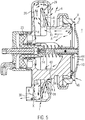
- Fig. 5 clarifies the vacuum valve in ventilated position by applying the piston 23 to its end position, so that the valve plate 9 is lifted in about only up to the height of the collar 46 from the sealing seat 44.
- Pressurized cleaning medium (arrows R) flows if necessary together with exhaust air (arrows A) from the tank T in the housing 8, wherein the valve disc 9 are cleaned at its upper and lower sides as well as the sealing seat 44, and also the interior of the Vacuum valve V.
- the mixture of exhaust air and cleaning medium is first passed through the annular flange 32 against the bottom of the drip tray 26, wherein liquid components from the cleaning medium (arrows X) collect at the bottom of the drip tray 26 and flow under the influence of gravity down to the discharge channel 30.
- Fig. 6 illustrates that the vacuum valve V can be installed alternatively with a stationary valve rod 12, for example, to a lower flange 7 of a pipe channel 47, wherein, however, the in Fig. 2 has been omitted and the response of the vacuum valve by the mass force in the active center of mass M is determined.
- the catching structure L also collects liquid components during a cleaning cycle and discharges them via the discharge channel 30 which opens vertically downwards.
- the crosspiece 2 of the tank safety fitting 1 in this embodiment is equipped with at least two vacuum valves V, each with a lying valve rod 12, in order to ensure a higher throughput and / or redundancy.
- the cross piece 2 even more than two vacuum valves V can be installed, which are ventilated during a cleaning cycle and cleaned from the nozzle openings 5 of the cleaning lance 4.
- the catching structure L is very reliable and acts when blowing off the tank T and cleaning the vacuum valve V as a centrifugal separator for entrained cleaning medium. This prevents contamination of the outside of the tank and a danger to nearby people. Due to the horizontal arrangement of the vacuum valve and the catching structure L, contamination of the valve plate rear side by dirt from the tank environment is avoided.
Landscapes
- Engineering & Computer Science (AREA)
- General Engineering & Computer Science (AREA)
- Mechanical Engineering (AREA)
- Details Of Valves (AREA)
- Pressure Vessels And Lids Thereof (AREA)
- Lift Valve (AREA)
Description
- Die Erfindung betrifft eine Tanksicherungsarmatur gemäß Oberbegriff des Anspruchs 1 und einen Tank gemäß Anspruch 11.
- Bei der Produktion flüssiger Lebensmittel, insbesondere in Brauereien, werden, z.B. bei Getränkeabfüllanlagen, Tanks mit einem Volumen bis zu 800 m3 eingesetzt, die nur begrenzte Festigkeit gegen Unterdruck haben. Gründe für das Entstehen eines Unterdrucks sind beispielsweise eine Systementleerung mittels Pumpe, ein unbeabsichtigtes Entleeren des Systems, oder physikalische Zustandsänderungen des bevorrateten Mediums und/oder Gärungsvorgänge, und dergleichen. Ein zulässiger Unterdruck in solchen Tanks beträgt oftmals nur 10 mbar. Zur Unterdruckabsicherung werden, beispielsweise in Tanksicherungsarmaturen, Vakuumventile in unterschiedlichen Baugrößen verwendet, welche einen Ansprechdruck von nur 3 bis 4 mbar haben und einen entsprechenden hohen Volumendurchsatz aufweisen. Es werden für größere Tanks nahezu ausschließlich gewichtsbelastete Vakuumventile eingesetzt, die mit senkrecht stehender Ventilstange verbaut sind, um die Reibung zu reduzieren und das Ansprechverhalten zu gewährleisten. Es gibt auch federbelastete Vakuumventile, die stehend verbaut sind, wobei hier das Nennweitenspektrum begrenzt ist, so dass senkrecht verbaute, federbelastete Vakuumventile für die Absicherung größerer Tanks nicht in Frage kommen. Die Vakuumventile sollen sitzreinigungsfähig sein und weisen meist eine Anlüftvorrichtung auf. Eine einwandfreie Reinigung ist erforderlich, da ein verschmutzter Dichtsitz zum Ankleben des Ventiltellers führen kann, so dass der Ansprechdruck den zulässigen Tankdruck überschreitet. Bei der Reinigung durch den Dichtsitz strömendes Medium wird bei einigen Vakuumventilen durch eine Fangschale aufgefangen und kontrolliert abgeführt. Bei gewichtsbelasteten Vakuumventilen ist aufgrund der Bauform eine Auffangvorrichtung für das Reinigungsmedium nicht vorhanden.
- Beim Zusammenfassen von Armaturen aus Vakuumventil, Sicherheitsventil gegen Überdruck, Messtechnik und Reinigungstechnik in einer Tanksicherungsarmatur ist der zwingend senkrechte Einbau des Vakuumventils nachteilig. Weist die Tanksicherungsarmatur ein Kreuzstück mit einem Zentralanschluss auf, benötigt das Vakuumventil ein separates Eckgehäuse, welches zusätzliche Kosten bedingt, schlechter zu reinigen ist und den Platzbedarf vergrößert. Alternativ wird ein Tankdeckel benötigt, in welchem Vakuumventile eingebaut werden. Dies erhöht ebenso die Kosten und erfordert einen höheren Aufwand, da unter Umständen separate Reinigungsdüsen mit entsprechender Verrohrung erforderlich sind. Es ist auch bekannt, ein Vakuumventil oben auf dem Kreuzstück der Tanksicherungsarmatur anzubringen. In diesem Fall kann jedoch nur ein einziges Vakuumventil vorgesehen sein und ist die Bauweise für den Einbau der Reinigungseinrichtungen nachteilig. Ein weiterer Nachteil bekannter Vakuumventile ist das Verhalten bei der Reinigung. Um den Dichtsitz zu reinigen, wird bei angehobenem Ventilteller aus Düsen Reinigungsmedium in Richtung auf den Dichtsitz gesprüht, welches zumindest teilweise mit hoher Geschwindigkeit durch den Dichtsitz tritt. Ist eine Auffangvorrichtung nicht vorhanden oder unzureichend ausgelegt, resultiert dies in einer unerwünschten Verschmutzung der Außenseite des Tanks. Beim Anlüften des Ventiltellers entspricht oftmals der Tankdruck nicht dem Umgebungsdruck. Herrscht im Tank nur minimaler Überdruck, entsteht durch das enorme Tankvolumen eine starke Luftströmung (Abblasen) nach außen durch das Vakuumventil, die Tropfen des Reinigungsmediums mitreißt. Dadurch entsteht auf der Außenseite oben am Tank eine Sprühnebelwolke, die den Tank verunreinigt und im Extremfall Personen treffen kann. Ein weiterer Nachteil gewichtsbelasteter und vertikal verbauter Vakuumventile ist, dass sich bauartbedingt Schmutz direkt auf der Rückseite des Ventiltellers sammelt.
- Aus einem Prospekt der Firma Albert Handtmann Armaturenfabrik GmbH und Co. KG, D-88400 Biberach an der Riss "Prozess- und Sicherheitsarmaturen" (www.handtmann.de), Seite 11, obere Abbildung, ist ein zum vertikalen Einbau ausgelegtes, federbelastetes Vakuumventil mit einer eine Ringschlitzöffnung des Gehäuses umgebenden Fangschale bekannt.
- Aus einem Prospekt der Firma GEA Tuchenhagen, 02/2010, "Tanksicherungssystem VARI-TOP", Seite 10/3, ist eine Tanksicherungsarmatur mit einem über ein Eckgehäuse an einem Kreuzstück verbauten vertikalen Vakuumventil bekannt, das gemäß Seite 10/9 eine Ventilteller-Baugruppe mit Ventilteller, Ventilstange und Gewichtsbelastung sowie einer Linearführung im Gehäuse aufweist. Das Vakuumventil wird senkrecht verbaut und weist unterhalb einer Ringschlitzöffnung des Gehäuses eine kragenartige Auffangschale für Reinigungsmedien auf, aus der ein Ableitkanal nach unten führt.
- Aus
US 5048560 A ist eine Tanksicherungsarmatur bekannt, die ein gewichtsbelastetes Überdruckventil mit einer aufgestülpten Schutzkappe sowie ein Klappen-Vakuumventil mit Gewichtsbelastung aufweist. Der Ventilteller des Vakuumventils wird bei der schwenkenden Öffnungsbewegung in einem seitlichen Scharnier geführt. Die Gewichtsbelastung ist auf eine Ventilstange des Ventiltellers aufgefädelt. Alternativ kann anstelle einer Gewichtsbelastung eine Federvorspannung benutzt werden. Das Vakuumventil ist vertikal installiert. -
- Der Erfindung liegt die Aufgabe zugrunde, ein Vakuumventil anzugeben, bei welchem unabhängig von der Einbaulage bei einem Reinigungszyklus Reinigungsmedium sicher aufgefangen und auch bei Abblasen des Tanks mitgerissenes Reinigungsmedium effektiv abgeschieden wird, sowie einen Tank mit verbesserten Gebrauchseigenschaften zu schaffen.
- Die gestellte Aufgabe wird mit den Merkmalen des Anspruchs 1 und des Anspruchs 11 gelöst.
- Der am Gehäuse angeordnete, in der Auffangschale frei endende, z.B. konische, Ringflansch leitet wie eine Schürze oder ein Schirm im Zusammenspiel mit dem überbogenen einwärts gewölbten Außenbereich der Auffangschale Reinigungsmedium zuverlässig in die Auffangschale. Gleichzeitig bewirkt der Ringflansch, dass z.B. beim Abblasen des Tanks austretendes Luft-Reinigungsmedium-Gemisch um den Ringflansch herum auf dessen Rückseite geleitet wird. Die durch die starke Umlenkung erzeugten Fliehkräfte scheiden in dem Gemisch enthaltene Tropfen in der Auffangschale ab. Auf die Rückseite des Ringflansches auftreffenden Tropfen haften dort und laufen unter der Schwerkraft nach unten, bis sie schließlich durch die Radialrippe in die Auffangschale geleitet werden. Aus der Auffangschale wird gesammeltes Reinigungsmedium über den Ableitkanal gezielt entsorgt. Selbst bei liegender Ventilstange wird eine Verschmutzung des Tankaußenbereiches vermieden. Auch wird der Ventilteller durch aus der Außenumgebung stammenden Schmutz nicht verschmutzt. Das Vakuumventil kann auch vertikal eingebaut werden, allerdings dann ohne Schließfeder, wobei durch den Leichtbau der Ventilteller-Baugruppe und dem Gewicht das ordnungsgemäße Ansprechverhalten des Vakuumventils, beispielsweise bei ca. 3 mbar, gewährleistet ist und die Fangstruktur Reinigungsmedium beim Reinigungszyklus und beim Abblasen des Tanks sicher sammelt und abführt. Bei horizontalem Einbau des Vakuumventils wird kein Totraum an einem Kreuzstück der Tanksicherungsarmatur geschaffen, was bei der Reinigung deutliche Vorteile bietet, da der Dichtsitz direkt gegenüber der Reinigungsleitung oder von Düsen im Kreuzstück sitzt und gründlich gereinigt wird. Wegen der kostengünstigen Ausführung des Vakuumventils und dessen geringem Platzbedarf an einem Kreuzstück können zur Steigerung des Durchsatzes mehrere, auch redundant wirkende Vakuumventile verbaut werden.
- Der Tank weist mit der Tanksicherungsarmatur ein verbessertes Betriebsverhalten auf, da beim Reinigen des Vakuumventils Verschmutzungen vermieden werden.
- In einer Ausführung hat der den Ringflansch umgreifende Außenwand-Bereich der Auffangschale C-förmigen Querschnitt mit einem in Richtung zum Ringflansch gebogenen Schalenrand. Dieses Konzept bringt Reinigungsmedium zuverlässig in die Auffangschale.
- Zweckmäßig hat der Ringflansch einen Konus-Öffnungswinkel zwischen etwa 180° und 120°, vorzugsweise etwa 130°. Diese Neigung begünstigt die Führung der Strömungen und das Abscheiden flüssiger Anteile des Reinigungsmediums.
- Günstig ist ferner an dem um den Rand des Ringflansches herumgreifenden und einwärts gekrümmten Schalenrand im Bereich eines Ableitkanals eine Verbreiterung vorgesehen, die sich, vorzugsweise, über etwa jeweils 30° bis 60° beiderseits der Position des Ableitkanals erstreckt, das Abscheiden des Reinigungsmediums begünstigt und ein Herausblasen von Reinigungsmedium beim Abblasen des Tanks unterdrückt.
- Die Verbreiterung kann ausgehend vom Schalenrand in Richtung vom Ringflansch weggebogen sein, z.B. mit konkaver Innenseite, um dort den Fangeffekt zu steigern.
- Besonders zweckmäßig ist in Ausrichtung auf den Ableitkanal an der Außenseite des Gehäuses wenigstens eine z.B. den Ringflansch durchdringende, im Wesentlichen radial stehende Radialrippe vorgesehen, die dem Dichtsitz zugewandt im Abstand vom Ringflansch beginnt, vorzugsweise an einer Umfangsnut des Gehäuses, und sich in liegender Einbauposition des Vakuumventils z.B. achsparallel bis zum Grund der Auffangschale erstreckt. Die Radialrippe nutzt die Adhäsionsneigung des flüssigen Reinigungsmediums, um dieses unter Schwerkraft- und Fliehkraft-Einfluss zu sammeln und in die Auffangschale zu leiten. Aus dem physikalischen Zusammenspiel zwischen dem Ringflansch, dem einwärts gekrümmten Schalenrand und der Radialrippe resultiert eine hervorragende Abscheidewirkung für das Reinigungsmedium. Die optional vorgesehene Umfangsnut im Gehäuse definiert eine Grenzlinie, über die hinaus das Reinigungsmedium nicht gelangt oder in der Reinigungsmedium gesammelt und unter Schwerkraft zur Radialrippe geführt wird.
- Zweckmäßig hat die Radialrippe einen gerundeten Beginn, in etwa gleichbleibende Wandstärke und in Richtung zum Boden der Auffangschale allmählich zunehmende Höhe, entweder mit einem im Wesentlichen geraden leicht abfallenden oder konkav gekrümmt in den Ringflansch einlaufenden Kamm. Diese Maßnahmen begünstigen das Ableiten des sich durch Adhäsion und/oder Fliehkraft an der Radialrippe sammelnden Reinigungsmediums in die Auffangschale und sind gusstechnisch günstig.
- In einer Ausführungsform ist das Vakuumventil mit im Wesentlichen waagrecht liegender Ventilstange, einer Schließfeder und untenliegendem, im Wesentlichen horizontal mündendem Ableitkanal, oder in einer anderen Ausführung mit im Wesentlichen vertikal stehender Ventilstange, ohne Schließfeder und annähernd vertikal mündendem Ableitkanal in der Tanksicherungsarmatur oder im Tank installiert.
- Herstellungstechnisch einfach und kostengünstig ist das Gehäuse mit der Fangschale, dem Ringflansch, der Radialrippe und dem Ableitkanal ein einstückiges Gußteil.
- Schließlich ist es speziell für die liegende Einbauposition des Vakuumventils zweckmäßig, wenn der Ventilteller als dünnwandiger bombierter Blechformteil mit hohl ausgebildeter Ventilstange und einem Hubbegrenzungs-Anschlag an der Ventilstange als Leichtbau-Ventilteller-Baugruppe ausgebildet sind, deren aktiver Massenschwerpunkt zumindest im Endabschnitt des Hubs des Ventiltellers an den Dichtsitz zwischen zwei beabstandeten Führungslagern einer Führung der Ventilstange liegt. Aufgrund der Leichtbauweise und der Positionierung des aktiven Massenschwerpunkts bleiben Reibungskräfte der Ventilstange vernachlässigbar und entstehen keine Winkelfehler, so dass selbst eine relativ schwache Schließfeder einerseits das ordnungsgemäße Ansprechen auf Unterdruck im Tank und andererseits ein sicheres Schließen des Vakuumventils sicherstellen kann.
- Anhand der Zeichnungen werden Ausführungsformen des Erfindungsgegenstandes erläutert. Es zeigen:
- Fig. 1
- einen Achsschnitt einer als nicht beschränkendes Ausführungsbeispiel gezeigten Tanksicherungsstruktur eines Tanks mit einem liegend verbauten Vakuumventil,
- Fig. 2
- einen Achsschnitt des Vakuumventils im geschlossenen Zustand, optional ausgerüstet mit einer Anlüftvorrichtung und einer Fangstruktur,
- Fig. 3
- eine geschnittene Perspektivansicht eines Gehäuses des Vakuumventils,
- Fig. 4
- einen Achsschnitt analog zu
Fig. 2 , bei auf Unterdruck ansprechendem Vakuumventil, - Fig. 5
- einen Achsschnitt analog zu
Fig. 2 undFig. 4 , bei zu einem Reinigungszyklus gelüftetem Vakuumventil, - Fig. 6
- das Vakuumventil in senkrechter Einbaulage als Alternativlösung im Achsschnitt, und
- Fig. 7
- ein Ausführungsbeispiel einer Tanksicherungsarmatur eines Tanks mit mehreren liegend verbauten Vakuumventilen.
-
Fig. 1 verdeutlicht eine Tanksicherungsarmatur 1 für einen Tank T, der über mindestens eine Leitung z.B. an eine Getränkeabfüllanlage angeschlossen ist. Die Tanksicherungsarmatur ist hier ausgestattet mit mindestens einem in etwa waagerecht liegend verbauten Vakuumventil V und einem angedeuteten Überdruckventil 6. Das Vakuumventil V ist mit einem Gehäuse 8 an einem Anschlussflansch 7 montiert, der seitlich aus einem stehenden Kreuzstück 2 herausführt, das auf der Tankwand 3 oder einem Aufsatzfuß 3 montiert ist. Das Vakuumventil V kann als Option mit einer integrierten Fangstruktur L und/oder einer Anlüftvorrichtung F ausgestattet sein. Im Kreuzstück 2 ist z.B. zentral eine Reinigungssonde 4 mit Düsenöffnungen 5 installiert, die von oben gespeist werden kann. Das Vakuumventil V dient zur Unterdruckabsicherung des Tanks T und öffnet bei einem vorbestimmten Unterdruck selbsttätig eine Verbindung zur Außenumgebung. Normalerweise befindet sich das Vakuumventil in der gezeigten Schließstellung, in der es prozessbedingten Überdruck im Tank T aufnimmt. Zum Reinigen zumindest eines Dichtsitzes 44 des Vakuumventils V kann dieses durch die Lüftvorrichtung F angelüftet werden, wobei dann unter Druck appliziertes Reinigungsmedium in der Fangstruktur L aufgefangen und abgeleitet wird. - In
Fig. 2 ist das Vakuumventil V in der Schließstellung gezeigt. Das Vakuumventil V weist im Gehäuse 8 eine Ventilteller-Baugruppe P auf, die in Leichtbauweise ausgeführt ist und einen Ventilteller 9 aus dünnwandigem Blech mit gleichbleibender Wandstärke mit einer zentralen Bombierung 10 nach rechts, einem peripheren flachen Dichtrand 11, sowie eine zentrale, hohl ausgebildete Ventilstange 12, die mit dem Ventilteller 9 verschweißt sein kann, und einen am freien Ende der Ventilstange 12 angebrachten Hubbegrenzungs-Anschlag 14 umfasst, der beispielsweise eingeschraubt ist. - Im Gehäuse 8 ist über mindestens einen Steg 16 zentral eine hier rohrförmige Führung 17 vorgesehen, in der zwei mit einem Abstand eingebaute Führungslager 18, 19 für die Ventilstange 12 untergebracht sind. Die Ventilstange 12 ist leichtgängig verschiebbar in den Führungslagern 18, 19 geführt. Die Führung 17 erstreckt sich in
Fig. 2 nach rechts über die Ebene des am Gehäuse 8 geformten, hier ringförmigen Dichtsitzes 44 hinaus in Richtung zum Ventilteller 9. Der aktive Massenschwerpunkt M der Ventilteller-Baugruppe P in der Leichtbauausführung liegt zumindest bei Kontakt zwischen dem Ventilteller 9 und dem Dichtsitz 44 in etwa in der Mitte zwischen den beiden Führungslagern 18, 19, so dass aus der aufgrund der Leichtbauweise ohnedies geringen Gewichtskraft der Ventilteller-Baugruppe P Winkelfehler des Ventiltellers 9 in Bezug auf den Dichtsitz 44 vermieden werden. Zwischen dem Anschlag 14 und der Führung 17 ist eine Schließfeder 15 eingesetzt, die nach Entfernen des Anschlags 14 wegnehmbar oder/und austauschbar ist, die Schließkraft zum Anlegen des Ventiltellers 9 an den Dichtsitz 44 generiert, und das Ansprechverhalten auf Unterdruck auf der Seite des Ventiltellers 9 mitbestimmt. - Der Dichtsitz 44 ist mit einer Lippendichtung 41 aus elastomerem Material ausgestattet, die beispielsweise durch einen auf das Gehäuse 8 aufgebrachten Ringeinsatz 42 festgelegt ist und, beispielsweise, bei geschlossenem Vakuumventil mit dem Dichtrand 11 zusammenarbeitet. Unter Bezug auf
Fig. 1 ist ferner inFig. 2 ein Ringflansch 7, 7' gezeigt, der über den Ringeinsatz 42 gegen einen Befestigungsflansch 45 des Gehäuses 8 geschoben und beispielsweise durch eine lösbare Spannschelle 43 festgelegt ist, beispielsweise um das Vakuumventil am Kreuzstück 2 inFig. 1 zu montieren. Der Ringflansch 7, 7' kann einen mit radialem Abstand über den Dichtsitz 44 vorstehenden Kragen 46 aufweisen, der zum Anschweißen dient, aber auch zur Strömungsführung, z.B. bei einem Reinigungszyklus, von Vorteil sein kann. - Alternativ kann das Vakuumventil V mit im Wesentlichen waagrecht liegender Ventilstange 12 auch an anderer Stelle des Tanks T verbaut sein.
- Auf einen Ansatz 20 des Gehäuses 8 ist die Anlüftvorrichtung F aufgebracht, die einen Zylinder 21 mit einem gegen eine Rückstellfeder 24 verstellbaren Kolben 23 enthält, der über einen Pneumatikanschluss 22 mit Druckluft beaufschlagbar bzw. entlastbar ist und mit dem Anschlag 14 zusammenwirkt, um das Vakuumventil V anzulüften (siehe
Fig. 3 ). Im Zylinder 21 kann ein Initiator 25 vorgesehen sein, um die Schließstellung des Ventiltellsers 9 zu überwachen. Die Anlüftvorrichtung F ist eine optionale Ausstattung des Vakuumventils V. - Als weitere Ausstattung des Vakuumventils V kann am Gehäuse 8 die Fangstruktur L angeformt sein. Diese umfasst eine kragenartige Auffangschale 26, deren Boden 27 nach außen und z.B. nach links geringfügig zurückweicht und zu einem hier horizontal mündenden Ableitkanal 30 führt. Die Auffangschale 26 besitzt einen etwa parallel zum Gehäuse verlaufenden, im Querschnitt C-förmigen Außenwandbereich 28, an welchen sich ein einwärts in Richtung zum Boden 27 überbogener Schalenrand 29 anschließt, der im Abstand vom Gehäuse 8 frei endet. Der Schalenrand 29 ist gebogen, um eine Führungsfläche für eine Luft- oder Reinigungsmediumströmung zu bilden, die ins Innere der Auffangschale 26 zielt. Die Auffangschale 26 ist an einer dem Dichtsitz 44 axial abgewandten Seite einer z.B. ringschlitzartigen, zur Außenumgebung offenen Öffnung Y des Gehäuses 8 angeordnet.
- An der gegenüberliegenden Seite der Öffnung Y ist am Gehäuse 8 ein z.B. konischer Ringflansch 32 (Konus-Öffnungswinkel zwischen etwa 180° und 120°, z.B. etwa 130°) angeformt, der mit einem beispielsweise kreisrunden freien Rand 34 endet und sich vom Gehäuse 8 z.B. schräg in Richtung vom Dichtsitz 44 weg in die Auffangschale 26 hinein erstreckt. Der Ringflansch 32 bildet eine Schürze oder einen Schirm, hat eine zum Boden 27 weisende Unterseite 35 und eine zum Schalenrand 29 weisende Oberseite 36. Der Rand 34 wird vom Schalenrand 29 mit Abstand übergriffen, d.h., der Schalenrand 29 endet näher am Gehäuse 8 als der Rand 34.
- Im Bereich des Ableitkanals 30 ist am Schalenrand 29 eine Verbreiterung 31 angeformt, die sich zu beiden Seiten der Position des Ableitkanals 30 über in etwa gleiche Winkelbereiche (z.B. 30° - 60°) erstreckt und nahe der Außenseite 36 des Ringflansches 32 endet. Die Fangstruktur L bildet einen um in etwa 180° umgelenkten Strömungsweg in das oder aus dem Vakuumventil V. Die Verbreiterung 31 kann (gestrichelt in
Fig. 2 und3 ) in Richtung vom Ringflansch 32 weg gebogen sein. - Ferner ist im Bereich des Ableitkanals 30 an der Außenseite des Gehäuses 8, z.B. beginnend an einer Umfangsnut 33, eine achsparallele Radialrippe 38 angeformt, welche z.B. den Ringflansch 32 durchdringt und in den Boden 27 der Auffangschale 26 einläuft. Der Beginn der Radialrippe 38 ist gerundet. Die Radialrippe 38 hat einen Kamm 40, dessen Höhe vom Beginn 39 bis zum Boden 27 der Auffangschale 26 allmählich zunimmt, so dass in liegender Einbauposition das Vakuumventil V zumindest der Abschnitt des Kamms 40 vom Beginn 39 bis zum Ringflansch 32 und oberhalb der Verbreitung 31 schräg nach links in die Auffangschale 26 abfällt. Gestrichelt alternativ ist in
Fig. 2 und3 angedeutet, dass der Kamm 40' konkav gekrümmt in den Ringflansch 32 eindringt. - Das Gehäuse 8 ist gemäß
Fig. 3 zweckmäßig als einstückiges Gußteil ausgebildet und enthält ein- oder angeformt alle vorerwähnten, zum Gehäuse 8 gehörigen Komponenten des Vakuumventils. -
Fig. 4 verdeutlicht das Vakuumventil V nach Ansprechen auf einen unzulässigen Unterdruck im Tank T. Die Ventilteller-Baugruppe P ist gegen die Schließfeder 15 bis auf Kontakt des Anschlags 14 an der Führung 17 vom Dichtsitz 44 abgehoben. Umgebungsluft (Pfeile B) strömt durch die Fangstruktur L in das Gehäuse 8 und durch den Dichtsitz 44 in den Tank T. Dabei wird die Umgebungsluft (Pfeile B) in der Fangstruktur L mindestens 3-fach umgelenkt. -
Fig. 5 verdeutlicht das Vakuumventil in angelüfteter Stellung durch Beaufschlagen des Kolbens 23 bis in dessen Endstellung, so dass der Ventilteller 9 in etwa nur bis auf die Höhe des Kragens 46 vom Dichtsitz 44 abgehoben ist. Unter Druck stehendes Reinigungsmedium (Pfeile R) strömt ggfs. zusammen mit Abluft (Pfeile A) aus dem Tank T in das Gehäuse 8, wobei der Ventilteller 9 an seinen Ober- und Unterseiten wie auch der Dichtsitz 44 gereinigt werden, und auch der Innenraum des Vakuumventils V. Die Mischung aus Abluft und Reinigungsmedium wird zunächst durch den Ringflansch 32 gegen den Boden der Auffangschale 26 geleitet, wobei sich flüssige Bestandteile aus dem Reinigungsmedium (Pfeile X) am Boden der Auffangschale 26 sammeln und unter Schwerkrafteinfluss nach unten zum Ableitkanal 30 strömen. Mit der Abluft (Pfeile A) mitgerissene flüssige Bestandteile des Reinigungsmediums gelangen auch in den Bereich des einwärts gewölbten Schalenrandes 29 und zur Außenseite 36 des Ringflansches 32, wobei sie sich durch Fliehkraftwirkung an der Außenseite 36 des Ringflansches 32 absetzen und zum Gehäuse 8 hin sowie zum Ableitkanal 30 nach unten geführt werden. Vom einwärts gewölbten Schalenrand 29 abtropfende flüssige Bestandteile fallen auf die Außenseite des Gehäuses 8 und fließen um dieses herum nach unten zur Radialrippe 38, an der sie durch Adhäsion haften und über den gerundeten Beginn 39 und den nach links abfallenden Kamm 40 oder 40' über die Verbreiterung 31 hinweg in Richtung zum Ableitkanal 30 geführt werden, während Abluft nach außen austritt. Über die Radialrippe 38 werden sogar aus dem Wirkbereich der Auffangschale 26 nach rechts ausgetretene Flüssigbestandteile des Reinigungsmediums zuverlässig zurück in die Auffangschale 26 gebracht. Dadurch unterbleibt eine Verschmutzung der Außenseite des Tanks. -
Fig. 6 verdeutlicht, dass das Vakuumventil V alternativ auch mit stehender Ventilstange 12 eingebaut werden kann, beispielsweise an einem unteren Anschlussflansch 7 eines Rohrkanals 47, wobei jedoch die inFig. 2 gezeigte Schließfeder weggelassen ist und das Ansprechverhalten des Vakuumventils durch die Massenkraft im aktiven Massenschwerpunkt M bestimmt ist. Die Fangstruktur L sammelt auch hier bei einem Reinigungszyklus flüssige Bestandteile und führt sie über den hier vertikal nach unten mündenden Ableitkanal 30 ab. - In
Fig. 7 ist angedeutet, dass das Kreuzstück 2 der Tanksicherungsarmatur 1 in dieser Ausführungsform mit mindestens zwei Vakuumventilen V, jeweils mit liegender Ventilstange 12, ausgestattet ist, um einen höheren Durchsatz und/oder Redundanz zu gewährleisten. An dem Kreuzstück 2 können sogar mehr als zwei Vakuumventile V verbaut sein, die bei einem Reinigungszyklus angelüftet und aus den Düsenöffnungen 5 der Reinigungslanze 4 gereinigt werden. - Durch den horizontalen Einbau ist es möglich, das Vakuumventil V totraumfrei in das Kreuzstück 2 der Tanksicherungsarmatur 1 einzugliedern. Dies bietet wesentliche Vorteile bei der Reinigung, da der Dichtsitz 44 im Kreuzstück 2 direkt gegenüber der Reinigungsleitung bzw. der Düsen 5 der Reinigungssonde liegt und leicht gereinigt werden kann. Ein Eckgehäuse zum Installieren des Vakuumventils am Kreuzstück entfällt, was einen Kostenvorteil hat und Bauraum spart. Die Fangstruktur L ist sehr zuverlässig und wirkt beim Abblasen des Tanks T und Reinigen des Vakuumventils V als Fliehkraftabscheider für mitgerissenes Reinigungsmedium. Dadurch wird eine Verschmutzung der Tankaußenseite und eine Gefährdung in der Nähe befindlicher Personen verhindert. Durch die horizontale Anordnung des Vakuumventils und die Fangstruktur L wird eine Verschmutzung der Ventilteller-Rückseite durch Schmutz aus der Tankumgebung vermieden.
Claims (11)
- Tanksicherungsarmatur (1) mit mindestens einem Vakuumventil (V), das in einem Gehäuse (8) einen Dichtsitz (44) und einen Ventilteller (9) aufweist, wobei das Gehäuse (8) dem Dichtsitz (44) abgewandt eine mit der Außenumgebung verbundene Öffnung (Y) für Zuluft, Abluft und/oder unter Druck stehendes Reinigungsmedium sowie an der Öffnung (Y) eine Auffangschale (26) aufweist, wobei an der dem Dichtsitz (44) zugewandten Seite der Öffnung (Y) ein Ringflansch (32) am Gehäuse (8) vorgesehen ist, der mit einem Rand (34) zumindest teilweise in der Auffangschale (26) frei endet, und die Auffangschale (26) und der Ringflansch (32) im Bereich der Öffnung (Y) einen mit mindestens einem Richtungswechsel versehenen Fliehkraft- und Abscheide-Strömungsweg begrenzen, dadurch gekennzeichnet, dass die an der anderen Seite der Öffnung (Y) angeordnete Auffangschale (26) einen im Abstand um den Rand (34) des Ringflansches (32) herumgreifenden Schalenrand (29) aufweist.
- Tanksicherungsarmatur nach Anspruch 1, dadurch gekennzeichnet, dass der den Ringflansch (32) umgreifende Außenrand-Bereich (28) der Auffangschale (26) C-förmigen Querschnitt aufweist und an seinem Ende mit dem Schalenrand (29) in Richtung zum Ringflansch (32) gebogen ist.
- Tanksicherungsarmatur nach Anspruch 1, dadurch gekennzeichnet, dass der Ringflansch (32) einen Konus-Öffnungswinkel zwischen etwa 180° und 120°, vorzugsweise etwa 130°, aufweist.
- Tanksicherungsarmatur nach Anspruch 1, dadurch gekennzeichnet, dass der Schalenrand (29) im Bereich eines Ableitkanals (30) eine Verbreiterung (31) aufweist, vorzugsweise über etwa jeweils 30° bis 60° beiderseits der Position des Ableitkanals (30).
- Tanksicherungsarmatur nach Anspruch 4, dadurch gekennzeichnet, dass die Verbreiterung (31) ausgehend vom Schalenrand (29) in Richtung vom Ringflansch (32) weg gebogen ist.
- Tanksicherungsarmatur nach Anspruch 4, dadurch gekennzeichnet, dass in Ausrichtung auf den Ableitkanal (30) an der Außenseite des Gehäuses (8) wenigstens eine im Wesentlichen radiale Radialrippe (38) vorgesehen ist, die dem Dichtsitz (44) zugewandt im Abstand vom Ringflansch (32) beginnt, vorzugsweise an einer Umfangsnut (33) des Gehäuses (8), und sich in etwa achsparallel zum Boden (27) der Auffangschale (26) erstreckt.
- Tanksicherungsarmatur nach Anspruch 6, dadurch gekennzeichnet, dass die Radialrippe (38) einen gerundeten Beginn (39), in etwa gleichbleibende Wandstärke und in Richtung zum Boden (27) der Auffangschale (26) allmählich zunehmende Höhe hat, vorzugsweise mit einem in waagerecht liegender Einbauposition des Vakuumventils (V) entweder im Wesentlichen gleichförmig abfallenden oder mit einer konkaven Krümmung in den Ringflansch (32) einlaufenden Kamm (40, 40').
- Tanksicherungsarmatur nach Anspruch 1, dadurch gekennzeichnet, dass das Vakuumventil (V) entweder mit im Wesentlichen waagerecht liegender Ventilstange (12), einer Schließfeder (15) und unterliegendem und annähernd horizontal mündenden Ableitkanal (30), oder mit im Wesentlichen vertikal stehender Ventilstange (12), ohne Schließfeder und annähernd vertikal untenliegend mündendem Ableitkanal (30) in der Tanksicherungsarmatur (1) installiert ist.
- Tanksicherungsarmatur nach Anspruch 1, dadurch gekennzeichnet, dass das Gehäuse (8) mit der Auffangschale (26), dem Ringflansch (32), der Radialrippe (38) und, vorzugsweise, dem Ableitkanal (30) ein einstückiges Gußteil ist.
- Tanksicherungsarmatur nach wenigstens einem der vorhergehenden Ansprüche, dadurch gekennzeichnet, dass der Ventilteller (9) als dünnwandiger, bombierter Blechformteil mit der hohl ausgebildeten Ventilstange (12) und einem Hubbegrenzungs-Anschlag (14) an der Ventilstange (12) als Leichtbau-Ventilteller-Baugruppe (P) ausgebildet sind, deren aktiver Massenschwerpunkt (M) bei Einbau mit in etwa waagerecht liegender Ventilstange (12) zumindest im Endabschnitt des Hubs des Ventiltellers (9) zum Dichtsitz (44) zwischen zwei beabstandeten Führungslagern (18, 19) einer gehäusefesten Führung (17) der Ventilstange (12) liegt.
- Tank (T) mit wenigstens einer Tanksicherungsarmatur (1) gemäß Anspruch 1, der über mindestens eine Leitung an eine Getränkeabfüllanlage anschließbar ist.
Priority Applications (1)
| Application Number | Priority Date | Filing Date | Title |
|---|---|---|---|
| PL16781098T PL3371494T3 (pl) | 2015-11-06 | 2016-10-11 | Armatura do zabezpieczania zbiornika i zbiornik |
Applications Claiming Priority (2)
| Application Number | Priority Date | Filing Date | Title |
|---|---|---|---|
| DE102015221896.1A DE102015221896A1 (de) | 2015-11-06 | 2015-11-06 | Tanksicherungsarmatur und Tank |
| PCT/EP2016/074261 WO2017076582A1 (de) | 2015-11-06 | 2016-10-11 | Tanksicherungsarmatur und tank |
Publications (2)
| Publication Number | Publication Date |
|---|---|
| EP3371494A1 EP3371494A1 (de) | 2018-09-12 |
| EP3371494B1 true EP3371494B1 (de) | 2019-09-11 |
Family
ID=57130373
Family Applications (1)
| Application Number | Title | Priority Date | Filing Date |
|---|---|---|---|
| EP16781098.5A Active EP3371494B1 (de) | 2015-11-06 | 2016-10-11 | Tanksicherungsarmatur und tank |
Country Status (7)
| Country | Link |
|---|---|
| EP (1) | EP3371494B1 (de) |
| CN (1) | CN208951397U (de) |
| DE (1) | DE102015221896A1 (de) |
| DK (1) | DK3371494T3 (de) |
| ES (1) | ES2752559T3 (de) |
| PL (1) | PL3371494T3 (de) |
| WO (1) | WO2017076582A1 (de) |
Family Cites Families (7)
| Publication number | Priority date | Publication date | Assignee | Title |
|---|---|---|---|---|
| US3724707A (en) * | 1971-05-05 | 1973-04-03 | F & E Mfg Co | Pressure-vacuum relief fuel filler cap |
| AU618316B2 (en) * | 1988-03-15 | 1991-12-19 | Autocaps (Aust) Pty. Limited | Improvements in or relating to radiator caps |
| US4998554A (en) * | 1988-09-16 | 1991-03-12 | Vacu-Purg, Inc. | Food pasteurization system vacuum breaker |
| US5048560A (en) | 1989-12-12 | 1991-09-17 | L&J Engineering Inc. | Sealing valve assembly |
| US5564457A (en) * | 1995-06-05 | 1996-10-15 | G & H Products Corp. | Vacuum breaker valve with CIP capability |
| DE102007030554B4 (de) * | 2007-06-30 | 2016-01-14 | Iveco Magirus Ag | Überlaufvorrichtung für einen Flüssigkeitsbehälter |
| WO2011031737A1 (en) * | 2009-09-08 | 2011-03-17 | Girard Equipment, Inc. | Vent valve and container therewith |
-
2015
- 2015-11-06 DE DE102015221896.1A patent/DE102015221896A1/de not_active Withdrawn
-
2016
- 2016-10-11 PL PL16781098T patent/PL3371494T3/pl unknown
- 2016-10-11 DK DK16781098.5T patent/DK3371494T3/da active
- 2016-10-11 CN CN201690001322.0U patent/CN208951397U/zh active Active
- 2016-10-11 EP EP16781098.5A patent/EP3371494B1/de active Active
- 2016-10-11 WO PCT/EP2016/074261 patent/WO2017076582A1/de not_active Ceased
- 2016-10-11 ES ES16781098T patent/ES2752559T3/es active Active
Also Published As
| Publication number | Publication date |
|---|---|
| CN208951397U (zh) | 2019-06-07 |
| PL3371494T3 (pl) | 2020-04-30 |
| DK3371494T3 (da) | 2019-12-16 |
| WO2017076582A1 (de) | 2017-05-11 |
| ES2752559T3 (es) | 2020-04-06 |
| EP3371494A1 (de) | 2018-09-12 |
| DE102015221896A1 (de) | 2017-05-11 |
Similar Documents
| Publication | Publication Date | Title |
|---|---|---|
| EP1880090B1 (de) | Vorrichtung zum reinigen von gas beim entlüften eines kurbelgehäuses | |
| EP2420456B1 (de) | Einwegventil | |
| DE69712497T2 (de) | Trennzentrifuge | |
| DE4300441C1 (de) | Vorrichtung zum Ent- und Belüften von Maschinengehäusen | |
| DE202020101954U1 (de) | Spritzpistole, die ein gutes Spritzergebnis liefert | |
| EP2848580B1 (de) | Vorrichtung zum Dosieren eines Füllprodukts in einen zu befüllenden Behälter | |
| EP2962765A1 (de) | Rückengetragenes sprühgerät und behälter für sprühmittel für ein rückengetragenes sprühgerät | |
| EP3071867B1 (de) | Abfüllventil für flüssigkeiten | |
| EP2937533B1 (de) | Entlüftungsmodul für einen Verbrennungsmotor | |
| WO2018137734A1 (de) | Trinkflaschenverschluss, insbesondere für eine isolierflasche | |
| EP3371493B1 (de) | Tanksicherungsarmatur und tank | |
| DE102010030456A1 (de) | Entlüftungsventil | |
| EP0774225A1 (de) | Ventil | |
| EP0602433A2 (de) | Behälterverschluss | |
| DE20112974U1 (de) | Behälterverschluss | |
| EP2628937B1 (de) | Abdeckhaube am aussenumfang eines betriebsstofftanks | |
| WO2017076582A1 (de) | Tanksicherungsarmatur und tank | |
| DE20209615U1 (de) | Selbstabdichtender Behälterverschluss | |
| WO2011110629A1 (de) | An eine brennkraftmaschine anflanschbarer ölnebelabscheider | |
| WO2009043332A1 (de) | Reinigungsvorrichtung für ein staubfilter | |
| EP3165800A1 (de) | Druckausgleichseinrichtung | |
| DE102005041129B4 (de) | Wassersprühvorrichtung | |
| DE920407C (de) | Vorrichtung zur Abgabe abgemessener Fluessigkeitsmengen | |
| DE202021103254U1 (de) | Entlüftungshaube für einen drucklosen Tank | |
| DE102011089002A1 (de) | Federbeinlager |
Legal Events
| Date | Code | Title | Description |
|---|---|---|---|
| STAA | Information on the status of an ep patent application or granted ep patent |
Free format text: STATUS: THE INTERNATIONAL PUBLICATION HAS BEEN MADE |
|
| PUAI | Public reference made under article 153(3) epc to a published international application that has entered the european phase |
Free format text: ORIGINAL CODE: 0009012 |
|
| STAA | Information on the status of an ep patent application or granted ep patent |
Free format text: STATUS: REQUEST FOR EXAMINATION WAS MADE |
|
| 17P | Request for examination filed |
Effective date: 20180111 |
|
| AK | Designated contracting states |
Kind code of ref document: A1 Designated state(s): AL AT BE BG CH CY CZ DE DK EE ES FI FR GB GR HR HU IE IS IT LI LT LU LV MC MK MT NL NO PL PT RO RS SE SI SK SM TR |
|
| AX | Request for extension of the european patent |
Extension state: BA ME |
|
| DAV | Request for validation of the european patent (deleted) | ||
| DAX | Request for extension of the european patent (deleted) | ||
| GRAP | Despatch of communication of intention to grant a patent |
Free format text: ORIGINAL CODE: EPIDOSNIGR1 |
|
| STAA | Information on the status of an ep patent application or granted ep patent |
Free format text: STATUS: GRANT OF PATENT IS INTENDED |
|
| INTG | Intention to grant announced |
Effective date: 20190328 |
|
| GRAS | Grant fee paid |
Free format text: ORIGINAL CODE: EPIDOSNIGR3 |
|
| GRAA | (expected) grant |
Free format text: ORIGINAL CODE: 0009210 |
|
| STAA | Information on the status of an ep patent application or granted ep patent |
Free format text: STATUS: THE PATENT HAS BEEN GRANTED |
|
| AK | Designated contracting states |
Kind code of ref document: B1 Designated state(s): AL AT BE BG CH CY CZ DE DK EE ES FI FR GB GR HR HU IE IS IT LI LT LU LV MC MK MT NL NO PL PT RO RS SE SI SK SM TR |
|
| REG | Reference to a national code |
Ref country code: GB Ref legal event code: FG4D Free format text: NOT ENGLISH |
|
| REG | Reference to a national code |
Ref country code: CH Ref legal event code: EP |
|
| REG | Reference to a national code |
Ref country code: AT Ref legal event code: REF Ref document number: 1178864 Country of ref document: AT Kind code of ref document: T Effective date: 20190915 |
|
| REG | Reference to a national code |
Ref country code: DE Ref legal event code: R096 Ref document number: 502016006609 Country of ref document: DE Ref country code: IE Ref legal event code: FG4D Free format text: LANGUAGE OF EP DOCUMENT: GERMAN |
|
| REG | Reference to a national code |
Ref country code: SE Ref legal event code: TRGR |
|
| REG | Reference to a national code |
Ref country code: DK Ref legal event code: T3 Effective date: 20191209 |
|
| REG | Reference to a national code |
Ref country code: NL Ref legal event code: MP Effective date: 20190911 |
|
| REG | Reference to a national code |
Ref country code: LT Ref legal event code: MG4D |
|
| PG25 | Lapsed in a contracting state [announced via postgrant information from national office to epo] |
Ref country code: FI Free format text: LAPSE BECAUSE OF FAILURE TO SUBMIT A TRANSLATION OF THE DESCRIPTION OR TO PAY THE FEE WITHIN THE PRESCRIBED TIME-LIMIT Effective date: 20190911 Ref country code: NO Free format text: LAPSE BECAUSE OF FAILURE TO SUBMIT A TRANSLATION OF THE DESCRIPTION OR TO PAY THE FEE WITHIN THE PRESCRIBED TIME-LIMIT Effective date: 20191211 Ref country code: BG Free format text: LAPSE BECAUSE OF FAILURE TO SUBMIT A TRANSLATION OF THE DESCRIPTION OR TO PAY THE FEE WITHIN THE PRESCRIBED TIME-LIMIT Effective date: 20191211 Ref country code: HR Free format text: LAPSE BECAUSE OF FAILURE TO SUBMIT A TRANSLATION OF THE DESCRIPTION OR TO PAY THE FEE WITHIN THE PRESCRIBED TIME-LIMIT Effective date: 20190911 Ref country code: LT Free format text: LAPSE BECAUSE OF FAILURE TO SUBMIT A TRANSLATION OF THE DESCRIPTION OR TO PAY THE FEE WITHIN THE PRESCRIBED TIME-LIMIT Effective date: 20190911 |
|
| PG25 | Lapsed in a contracting state [announced via postgrant information from national office to epo] |
Ref country code: RS Free format text: LAPSE BECAUSE OF FAILURE TO SUBMIT A TRANSLATION OF THE DESCRIPTION OR TO PAY THE FEE WITHIN THE PRESCRIBED TIME-LIMIT Effective date: 20190911 Ref country code: AL Free format text: LAPSE BECAUSE OF FAILURE TO SUBMIT A TRANSLATION OF THE DESCRIPTION OR TO PAY THE FEE WITHIN THE PRESCRIBED TIME-LIMIT Effective date: 20190911 Ref country code: LV Free format text: LAPSE BECAUSE OF FAILURE TO SUBMIT A TRANSLATION OF THE DESCRIPTION OR TO PAY THE FEE WITHIN THE PRESCRIBED TIME-LIMIT Effective date: 20190911 Ref country code: GR Free format text: LAPSE BECAUSE OF FAILURE TO SUBMIT A TRANSLATION OF THE DESCRIPTION OR TO PAY THE FEE WITHIN THE PRESCRIBED TIME-LIMIT Effective date: 20191212 |
|
| REG | Reference to a national code |
Ref country code: ES Ref legal event code: FG2A Ref document number: 2752559 Country of ref document: ES Kind code of ref document: T3 Effective date: 20200406 |
|
| PG25 | Lapsed in a contracting state [announced via postgrant information from national office to epo] |
Ref country code: NL Free format text: LAPSE BECAUSE OF FAILURE TO SUBMIT A TRANSLATION OF THE DESCRIPTION OR TO PAY THE FEE WITHIN THE PRESCRIBED TIME-LIMIT Effective date: 20190911 Ref country code: PT Free format text: LAPSE BECAUSE OF FAILURE TO SUBMIT A TRANSLATION OF THE DESCRIPTION OR TO PAY THE FEE WITHIN THE PRESCRIBED TIME-LIMIT Effective date: 20200113 Ref country code: RO Free format text: LAPSE BECAUSE OF FAILURE TO SUBMIT A TRANSLATION OF THE DESCRIPTION OR TO PAY THE FEE WITHIN THE PRESCRIBED TIME-LIMIT Effective date: 20190911 Ref country code: EE Free format text: LAPSE BECAUSE OF FAILURE TO SUBMIT A TRANSLATION OF THE DESCRIPTION OR TO PAY THE FEE WITHIN THE PRESCRIBED TIME-LIMIT Effective date: 20190911 |
|
| PG25 | Lapsed in a contracting state [announced via postgrant information from national office to epo] |
Ref country code: SK Free format text: LAPSE BECAUSE OF FAILURE TO SUBMIT A TRANSLATION OF THE DESCRIPTION OR TO PAY THE FEE WITHIN THE PRESCRIBED TIME-LIMIT Effective date: 20190911 Ref country code: SM Free format text: LAPSE BECAUSE OF FAILURE TO SUBMIT A TRANSLATION OF THE DESCRIPTION OR TO PAY THE FEE WITHIN THE PRESCRIBED TIME-LIMIT Effective date: 20190911 Ref country code: CZ Free format text: LAPSE BECAUSE OF FAILURE TO SUBMIT A TRANSLATION OF THE DESCRIPTION OR TO PAY THE FEE WITHIN THE PRESCRIBED TIME-LIMIT Effective date: 20190911 Ref country code: IS Free format text: LAPSE BECAUSE OF FAILURE TO SUBMIT A TRANSLATION OF THE DESCRIPTION OR TO PAY THE FEE WITHIN THE PRESCRIBED TIME-LIMIT Effective date: 20200224 |
|
| REG | Reference to a national code |
Ref country code: CH Ref legal event code: PL |
|
| REG | Reference to a national code |
Ref country code: DE Ref legal event code: R097 Ref document number: 502016006609 Country of ref document: DE |
|
| PLBE | No opposition filed within time limit |
Free format text: ORIGINAL CODE: 0009261 |
|
| STAA | Information on the status of an ep patent application or granted ep patent |
Free format text: STATUS: NO OPPOSITION FILED WITHIN TIME LIMIT |
|
| PG2D | Information on lapse in contracting state deleted |
Ref country code: IS |
|
| PG25 | Lapsed in a contracting state [announced via postgrant information from national office to epo] |
Ref country code: CH Free format text: LAPSE BECAUSE OF NON-PAYMENT OF DUE FEES Effective date: 20191031 Ref country code: LI Free format text: LAPSE BECAUSE OF NON-PAYMENT OF DUE FEES Effective date: 20191031 Ref country code: LU Free format text: LAPSE BECAUSE OF NON-PAYMENT OF DUE FEES Effective date: 20191011 Ref country code: IS Free format text: LAPSE BECAUSE OF FAILURE TO SUBMIT A TRANSLATION OF THE DESCRIPTION OR TO PAY THE FEE WITHIN THE PRESCRIBED TIME-LIMIT Effective date: 20200112 |
|
| REG | Reference to a national code |
Ref country code: BE Ref legal event code: MM Effective date: 20191031 |
|
| 26N | No opposition filed |
Effective date: 20200615 |
|
| PG25 | Lapsed in a contracting state [announced via postgrant information from national office to epo] |
Ref country code: MC Free format text: LAPSE BECAUSE OF FAILURE TO SUBMIT A TRANSLATION OF THE DESCRIPTION OR TO PAY THE FEE WITHIN THE PRESCRIBED TIME-LIMIT Effective date: 20190911 Ref country code: BE Free format text: LAPSE BECAUSE OF NON-PAYMENT OF DUE FEES Effective date: 20191031 Ref country code: SI Free format text: LAPSE BECAUSE OF FAILURE TO SUBMIT A TRANSLATION OF THE DESCRIPTION OR TO PAY THE FEE WITHIN THE PRESCRIBED TIME-LIMIT Effective date: 20190911 |
|
| PG25 | Lapsed in a contracting state [announced via postgrant information from national office to epo] |
Ref country code: IE Free format text: LAPSE BECAUSE OF NON-PAYMENT OF DUE FEES Effective date: 20191011 |
|
| PG25 | Lapsed in a contracting state [announced via postgrant information from national office to epo] |
Ref country code: CY Free format text: LAPSE BECAUSE OF FAILURE TO SUBMIT A TRANSLATION OF THE DESCRIPTION OR TO PAY THE FEE WITHIN THE PRESCRIBED TIME-LIMIT Effective date: 20190911 |
|
| GBPC | Gb: european patent ceased through non-payment of renewal fee |
Effective date: 20201011 |
|
| PG25 | Lapsed in a contracting state [announced via postgrant information from national office to epo] |
Ref country code: MT Free format text: LAPSE BECAUSE OF FAILURE TO SUBMIT A TRANSLATION OF THE DESCRIPTION OR TO PAY THE FEE WITHIN THE PRESCRIBED TIME-LIMIT Effective date: 20190911 Ref country code: HU Free format text: LAPSE BECAUSE OF FAILURE TO SUBMIT A TRANSLATION OF THE DESCRIPTION OR TO PAY THE FEE WITHIN THE PRESCRIBED TIME-LIMIT; INVALID AB INITIO Effective date: 20161011 |
|
| PG25 | Lapsed in a contracting state [announced via postgrant information from national office to epo] |
Ref country code: GB Free format text: LAPSE BECAUSE OF NON-PAYMENT OF DUE FEES Effective date: 20201011 |
|
| PG25 | Lapsed in a contracting state [announced via postgrant information from national office to epo] |
Ref country code: TR Free format text: LAPSE BECAUSE OF FAILURE TO SUBMIT A TRANSLATION OF THE DESCRIPTION OR TO PAY THE FEE WITHIN THE PRESCRIBED TIME-LIMIT Effective date: 20190911 |
|
| PG25 | Lapsed in a contracting state [announced via postgrant information from national office to epo] |
Ref country code: MK Free format text: LAPSE BECAUSE OF FAILURE TO SUBMIT A TRANSLATION OF THE DESCRIPTION OR TO PAY THE FEE WITHIN THE PRESCRIBED TIME-LIMIT Effective date: 20190911 |
|
| REG | Reference to a national code |
Ref country code: AT Ref legal event code: MM01 Ref document number: 1178864 Country of ref document: AT Kind code of ref document: T Effective date: 20211011 |
|
| PG25 | Lapsed in a contracting state [announced via postgrant information from national office to epo] |
Ref country code: AT Free format text: LAPSE BECAUSE OF NON-PAYMENT OF DUE FEES Effective date: 20211011 |
|
| P01 | Opt-out of the competence of the unified patent court (upc) registered |
Effective date: 20230523 |
|
| PGFP | Annual fee paid to national office [announced via postgrant information from national office to epo] |
Ref country code: PL Payment date: 20250915 Year of fee payment: 10 Ref country code: IT Payment date: 20250922 Year of fee payment: 10 |
|
| PGFP | Annual fee paid to national office [announced via postgrant information from national office to epo] |
Ref country code: FR Payment date: 20250908 Year of fee payment: 10 |
|
| PGFP | Annual fee paid to national office [announced via postgrant information from national office to epo] |
Ref country code: SE Payment date: 20250910 Year of fee payment: 10 |
|
| PGFP | Annual fee paid to national office [announced via postgrant information from national office to epo] |
Ref country code: DE Payment date: 20250902 Year of fee payment: 10 |
|
| PGFP | Annual fee paid to national office [announced via postgrant information from national office to epo] |
Ref country code: DK Payment date: 20251014 Year of fee payment: 10 |
|
| PGFP | Annual fee paid to national office [announced via postgrant information from national office to epo] |
Ref country code: ES Payment date: 20251105 Year of fee payment: 10 |