EP3371490B1 - Valve device - Google Patents
Valve device Download PDFInfo
- Publication number
- EP3371490B1 EP3371490B1 EP16862530.9A EP16862530A EP3371490B1 EP 3371490 B1 EP3371490 B1 EP 3371490B1 EP 16862530 A EP16862530 A EP 16862530A EP 3371490 B1 EP3371490 B1 EP 3371490B1
- Authority
- EP
- European Patent Office
- Prior art keywords
- valve device
- bolts
- disc
- stop
- disc parts
- Prior art date
- Legal status (The legal status is an assumption and is not a legal conclusion. Google has not performed a legal analysis and makes no representation as to the accuracy of the status listed.)
- Active
Links
- 230000007246 mechanism Effects 0.000 claims description 37
- 239000007789 gas Substances 0.000 claims description 27
- 230000004913 activation Effects 0.000 claims description 24
- 239000012530 fluid Substances 0.000 claims description 20
- 239000007788 liquid Substances 0.000 claims description 20
- 230000008859 change Effects 0.000 claims description 3
- 230000003247 decreasing effect Effects 0.000 claims description 3
- 230000001419 dependent effect Effects 0.000 claims 2
- 230000003213 activating effect Effects 0.000 claims 1
- 230000001747 exhibiting effect Effects 0.000 claims 1
- 239000000843 powder Substances 0.000 description 4
- 238000010276 construction Methods 0.000 description 3
- 230000002457 bidirectional effect Effects 0.000 description 2
- 230000004048 modification Effects 0.000 description 2
- 238000012986 modification Methods 0.000 description 2
- 230000008901 benefit Effects 0.000 description 1
- 230000003111 delayed effect Effects 0.000 description 1
Images


Classifications
-
- F—MECHANICAL ENGINEERING; LIGHTING; HEATING; WEAPONS; BLASTING
- F16—ENGINEERING ELEMENTS AND UNITS; GENERAL MEASURES FOR PRODUCING AND MAINTAINING EFFECTIVE FUNCTIONING OF MACHINES OR INSTALLATIONS; THERMAL INSULATION IN GENERAL
- F16K—VALVES; TAPS; COCKS; ACTUATING-FLOATS; DEVICES FOR VENTING OR AERATING
- F16K3/00—Gate valves or sliding valves, i.e. cut-off apparatus with closing members having a sliding movement along the seat for opening and closing
- F16K3/02—Gate valves or sliding valves, i.e. cut-off apparatus with closing members having a sliding movement along the seat for opening and closing with flat sealing faces; Packings therefor
- F16K3/03—Gate valves or sliding valves, i.e. cut-off apparatus with closing members having a sliding movement along the seat for opening and closing with flat sealing faces; Packings therefor with a closure member in the form of an iris-diaphragm
-
- F—MECHANICAL ENGINEERING; LIGHTING; HEATING; WEAPONS; BLASTING
- F16—ENGINEERING ELEMENTS AND UNITS; GENERAL MEASURES FOR PRODUCING AND MAINTAINING EFFECTIVE FUNCTIONING OF MACHINES OR INSTALLATIONS; THERMAL INSULATION IN GENERAL
- F16K—VALVES; TAPS; COCKS; ACTUATING-FLOATS; DEVICES FOR VENTING OR AERATING
- F16K3/00—Gate valves or sliding valves, i.e. cut-off apparatus with closing members having a sliding movement along the seat for opening and closing
- F16K3/22—Gate valves or sliding valves, i.e. cut-off apparatus with closing members having a sliding movement along the seat for opening and closing with sealing faces shaped as surfaces of solids of revolution
- F16K3/24—Gate valves or sliding valves, i.e. cut-off apparatus with closing members having a sliding movement along the seat for opening and closing with sealing faces shaped as surfaces of solids of revolution with cylindrical valve members
- F16K3/26—Gate valves or sliding valves, i.e. cut-off apparatus with closing members having a sliding movement along the seat for opening and closing with sealing faces shaped as surfaces of solids of revolution with cylindrical valve members with fluid passages in the valve member
-
- E—FIXED CONSTRUCTIONS
- E21—EARTH OR ROCK DRILLING; MINING
- E21B—EARTH OR ROCK DRILLING; OBTAINING OIL, GAS, WATER, SOLUBLE OR MELTABLE MATERIALS OR A SLURRY OF MINERALS FROM WELLS
- E21B34/00—Valve arrangements for boreholes or wells
- E21B34/06—Valve arrangements for boreholes or wells in wells
- E21B34/08—Valve arrangements for boreholes or wells in wells responsive to flow or pressure of the fluid obtained
-
- F—MECHANICAL ENGINEERING; LIGHTING; HEATING; WEAPONS; BLASTING
- F16—ENGINEERING ELEMENTS AND UNITS; GENERAL MEASURES FOR PRODUCING AND MAINTAINING EFFECTIVE FUNCTIONING OF MACHINES OR INSTALLATIONS; THERMAL INSULATION IN GENERAL
- F16K—VALVES; TAPS; COCKS; ACTUATING-FLOATS; DEVICES FOR VENTING OR AERATING
- F16K17/00—Safety valves; Equalising valves, e.g. pressure relief valves
- F16K17/02—Safety valves; Equalising valves, e.g. pressure relief valves opening on surplus pressure on one side; closing on insufficient pressure on one side
- F16K17/04—Safety valves; Equalising valves, e.g. pressure relief valves opening on surplus pressure on one side; closing on insufficient pressure on one side spring-loaded
- F16K17/0446—Safety valves; Equalising valves, e.g. pressure relief valves opening on surplus pressure on one side; closing on insufficient pressure on one side spring-loaded with an obturating member having at least a component of their opening and closing motion not perpendicular to the closing faces
- F16K17/0453—Safety valves; Equalising valves, e.g. pressure relief valves opening on surplus pressure on one side; closing on insufficient pressure on one side spring-loaded with an obturating member having at least a component of their opening and closing motion not perpendicular to the closing faces the member being a diaphragm
-
- F—MECHANICAL ENGINEERING; LIGHTING; HEATING; WEAPONS; BLASTING
- F16—ENGINEERING ELEMENTS AND UNITS; GENERAL MEASURES FOR PRODUCING AND MAINTAINING EFFECTIVE FUNCTIONING OF MACHINES OR INSTALLATIONS; THERMAL INSULATION IN GENERAL
- F16K—VALVES; TAPS; COCKS; ACTUATING-FLOATS; DEVICES FOR VENTING OR AERATING
- F16K17/00—Safety valves; Equalising valves, e.g. pressure relief valves
- F16K17/20—Excess-flow valves
- F16K17/22—Excess-flow valves actuated by the difference of pressure between two places in the flow line
-
- F—MECHANICAL ENGINEERING; LIGHTING; HEATING; WEAPONS; BLASTING
- F16—ENGINEERING ELEMENTS AND UNITS; GENERAL MEASURES FOR PRODUCING AND MAINTAINING EFFECTIVE FUNCTIONING OF MACHINES OR INSTALLATIONS; THERMAL INSULATION IN GENERAL
- F16K—VALVES; TAPS; COCKS; ACTUATING-FLOATS; DEVICES FOR VENTING OR AERATING
- F16K17/00—Safety valves; Equalising valves, e.g. pressure relief valves
- F16K17/36—Safety valves; Equalising valves, e.g. pressure relief valves actuated in consequence of extraneous circumstances, e.g. shock, change of position
- F16K17/363—Safety valves; Equalising valves, e.g. pressure relief valves actuated in consequence of extraneous circumstances, e.g. shock, change of position the closure members being rotatable or pivoting
-
- F—MECHANICAL ENGINEERING; LIGHTING; HEATING; WEAPONS; BLASTING
- F16—ENGINEERING ELEMENTS AND UNITS; GENERAL MEASURES FOR PRODUCING AND MAINTAINING EFFECTIVE FUNCTIONING OF MACHINES OR INSTALLATIONS; THERMAL INSULATION IN GENERAL
- F16K—VALVES; TAPS; COCKS; ACTUATING-FLOATS; DEVICES FOR VENTING OR AERATING
- F16K3/00—Gate valves or sliding valves, i.e. cut-off apparatus with closing members having a sliding movement along the seat for opening and closing
- F16K3/22—Gate valves or sliding valves, i.e. cut-off apparatus with closing members having a sliding movement along the seat for opening and closing with sealing faces shaped as surfaces of solids of revolution
- F16K3/24—Gate valves or sliding valves, i.e. cut-off apparatus with closing members having a sliding movement along the seat for opening and closing with sealing faces shaped as surfaces of solids of revolution with cylindrical valve members
- F16K3/26—Gate valves or sliding valves, i.e. cut-off apparatus with closing members having a sliding movement along the seat for opening and closing with sealing faces shaped as surfaces of solids of revolution with cylindrical valve members with fluid passages in the valve member
- F16K3/267—Combination of a sliding valve and a lift valve
-
- F—MECHANICAL ENGINEERING; LIGHTING; HEATING; WEAPONS; BLASTING
- F16—ENGINEERING ELEMENTS AND UNITS; GENERAL MEASURES FOR PRODUCING AND MAINTAINING EFFECTIVE FUNCTIONING OF MACHINES OR INSTALLATIONS; THERMAL INSULATION IN GENERAL
- F16L—PIPES; JOINTS OR FITTINGS FOR PIPES; SUPPORTS FOR PIPES, CABLES OR PROTECTIVE TUBING; MEANS FOR THERMAL INSULATION IN GENERAL
- F16L55/00—Devices or appurtenances for use in, or in connection with, pipes or pipe systems
- F16L55/10—Means for stopping flow from or in pipes or hoses
- F16L55/1015—Couplings closed automatically when disengaging force exceeds preselected value
-
- F—MECHANICAL ENGINEERING; LIGHTING; HEATING; WEAPONS; BLASTING
- F16—ENGINEERING ELEMENTS AND UNITS; GENERAL MEASURES FOR PRODUCING AND MAINTAINING EFFECTIVE FUNCTIONING OF MACHINES OR INSTALLATIONS; THERMAL INSULATION IN GENERAL
- F16L—PIPES; JOINTS OR FITTINGS FOR PIPES; SUPPORTS FOR PIPES, CABLES OR PROTECTIVE TUBING; MEANS FOR THERMAL INSULATION IN GENERAL
- F16L55/00—Devices or appurtenances for use in, or in connection with, pipes or pipe systems
- F16L55/10—Means for stopping flow from or in pipes or hoses
- F16L55/1022—Fluid cut-off devices automatically actuated
-
- F—MECHANICAL ENGINEERING; LIGHTING; HEATING; WEAPONS; BLASTING
- F41—WEAPONS
- F41A—FUNCTIONAL FEATURES OR DETAILS COMMON TO BOTH SMALLARMS AND ORDNANCE, e.g. CANNONS; MOUNTINGS FOR SMALLARMS OR ORDNANCE
- F41A21/00—Barrels; Gun tubes; Muzzle attachments; Barrel mounting means
- F41A21/30—Silencers
-
- F—MECHANICAL ENGINEERING; LIGHTING; HEATING; WEAPONS; BLASTING
- F41—WEAPONS
- F41A—FUNCTIONAL FEATURES OR DETAILS COMMON TO BOTH SMALLARMS AND ORDNANCE, e.g. CANNONS; MOUNTINGS FOR SMALLARMS OR ORDNANCE
- F41A21/00—Barrels; Gun tubes; Muzzle attachments; Barrel mounting means
- F41A21/32—Muzzle attachments or glands
- F41A21/34—Flash dampers
-
- Y—GENERAL TAGGING OF NEW TECHNOLOGICAL DEVELOPMENTS; GENERAL TAGGING OF CROSS-SECTIONAL TECHNOLOGIES SPANNING OVER SEVERAL SECTIONS OF THE IPC; TECHNICAL SUBJECTS COVERED BY FORMER USPC CROSS-REFERENCE ART COLLECTIONS [XRACs] AND DIGESTS
- Y10—TECHNICAL SUBJECTS COVERED BY FORMER USPC
- Y10T—TECHNICAL SUBJECTS COVERED BY FORMER US CLASSIFICATION
- Y10T137/00—Fluid handling
- Y10T137/8593—Systems
- Y10T137/86928—Sequentially progressive opening or closing of plural valves
- Y10T137/86936—Pressure equalizing or auxiliary shunt flow
- Y10T137/86944—One valve seats against other valve [e.g., concentric valves]
Definitions
- the present invention is related to a valve device, according to the preamble of claim 1.
- the present invention is related valve device for fluid, liquid or gas, and a typical application for the valve device according to the present invention will be as a stop valve/safety valve, but it can also be modified to an adjustable valve.
- the valve device can be used for fluid, liquid or gas in all thinkable applications where it is necessary to close rapidly and safely, e.g. blow-out preventer or other similar safety valves, in a sound directing and/muzzle flash dampening device, or as an adjustable device in a pipeline or similar for transport or control of fluid, liquid or gas.
- a valve of the known art is disclosed in US 2008/0121298 A1 .
- a lack of prior art valve devices is that they are custom-made for the actual application, and that they often do not provide a rapid and safe opening or closing. It is further a lack of known valve devices is that they require external manipulation for opening or closing.
- sensor means are arranged which provide information to an actuator which further shall open or close the valve.
- valve device which does not need to be custom-made to the actual application, but can be used in all kinds of applications independent of it is fluid, gas or liquid.
- the main object of the present invention is to provide a valve device which entirely or partly solves the lacks of prior art.
- An object of the present invention is to provide a valve device which is arranged for even closing/opening for fluid, liquid or gas in the valve device.
- An object of the present invention is to provide a valve device which can function as a balancing valve, arranged such that pressure in front or behind the valve device activates movable parts of the valve in greater or lesser degree, and maintains the flow (of fluid, liquid or gas) at a desired level/velocity.
- a further object with the present invention is to provide a controllable valve device or that the valve device comprises a controllable actuator mechanism for adjustment of properties of the valve device.
- valve device according to the present invention is disclosed in claim 1. Preferable features of the valve device are disclosed in the remaining claims.
- the valve device according to a first embodiment of the present invention is formed by an outer tube which at one end thereof is provided with a connection/fastening device to existing tube, pipeline or similar, and which at its other end is provided with a corresponding connection to tube, pipeline or similar, such that the mentioned valve device can be arranged between two tube sections or similar, transporting fluid, liquid or gas.
- the mentioned connection/fastening device can possibly also be formed by a reinforced cover.
- valve device is formed by an outer tube which at one end thereof is provided with a connection/fastening device to a barrel of a firearm, such that the mentioned valve device can be arranged in the extension of the barrel of the firearm.
- a (reinforced) cover which exhibits a central hole adapted for passing of a projectile fired via the barrel of the firearm.
- the valve device further comprises a closing mechanism which is formed by stop discs arranged movably to bolts or rods extending in longitudinal direction of the valve device, between mentioned connections/fastening devices/cover, i.e. at inside of the tube, or where the stop discs are fixed to the bolts or rods which are movable in longitudinal direction and the stop discs are therethrough movable in longitudinal direction of the valve device.
- a closing mechanism which is formed by stop discs arranged movably to bolts or rods extending in longitudinal direction of the valve device, between mentioned connections/fastening devices/cover, i.e. at inside of the tube, or where the stop discs are fixed to the bolts or rods which are movable in longitudinal direction and the stop discs are therethrough movable in longitudinal direction of the valve device.
- the stop discs are separated in longitudinal direction of the valve device and are connected by at least three rods or activation bolts extending between the two mentioned stop discs with increasing or decreasing angle.
- the stop discs are further provided with a central through hole where fluid, liquid or gas can flow.
- the valve device further comprises a closing disc formed by at least two disc parts, which are movably arranged to the mentioned at least three rods or activation bolts, between the mentioned stop discs.
- the mentioned disc parts exhibit slots of such a form and such angles that they are forced to change relative position as the movable rods/activation bolts in longitudinal direction of the valve device or that the rods/activation bolts move in the longitudinal direction of the valve device.
- valve device according to the present invention it comprises cylindrical aperture box, fixed or movably arranged in the tube of the valve device, between the mentioned stop discs, which aperture box exhibits an inner cavity for accommodating the closing disc formed by at least two disc parts, and is provided with a central through hole as the first and second stop disc, and where it in connection with the central hole, i.e. outside the circumference thereof, also is arranged slots for the at least three rods or activation bolts which thus extend through the aperture box when this is arranged between the first and second stop disc.
- the present invention also could function as a non return valve.
- the mentioned first and second stop disc may further be spring-loaded, or that the bolts or rods extending in longitudinal direction of the valve device themselves are spring-loaded, alternatively the aperture box, such that it is required a certain force before the closing mechanism is activated.
- the mentioned spring-functionality of the bolts/rods/aperture box/stop discs can further be used such that after the pressure in the mentioned chamber again drops, the rods/bolts/aperture box/stop discs are returned and the valve device again opens as the disc parts are forced from each other, outwards towards the inner diameter of the tube.
- the mentioned valve device can further be considered as a module-based valve device where several such closing mechanisms, i.e. first and second stop discs, activation bolts, possibly aperture box, and closing disc in disc parts, can be arranged after one another in the same tube for increased safety or possibly close at different pressure.
- first and second stop discs, activation bolts, possibly aperture box, and closing disc in disc parts can be arranged after one another in the same tube for increased safety or possibly close at different pressure.
- the above mentioned closing mechanism can further be automated by that the mentioned stop discs or bolts/rods or aperture box is arranged to an actuator mechanism and therethrough the opening and closing can be adjusted by moving the stop discs/bolts/rods/aperture box in longitudinal direction of the valve device and therethrough determine the opening formed by the position of the disc parts in relation to each other.
- the valve device according to the present invention can further be arranged as a balancing valve, arranged such that the pressure in front or behind the closing mechanism activates the valve parts in greater or lesser degree, and maintains the flow (of fluid, liquid or gas) at a certain level/velocity.
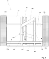
- FIG. 1 shows a principle drawing of a valve device 10 according to the present invention, in a cross-sectional view
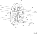
- Figure 2 showing details of the closing mechanism of the valve device, seen inclined from the front, where parts of the valve device 10 are removed for revealing inner details
- Figure 3 showing details of the closing mechanism in entirely closed position where parts of the valve device 10 are removed for revealing inner details
- Figure 4 showing details of a closing mechanism of the valve device in partly open position where parts of the valve device 10 are removed for revealing inner details.
- the valve device 10 is formed by an outer tube 11 which at one end thereof is provided with a connection/fastening device 12a for existing tube, pipeline or similar (not shown), and which at the other end thereof is provided with a corresponding connection/fastening device 12b for tube, pipeline or similar (not shown), such that the mentioned valve device 10 can be arranged between two tube sections or similar transporting fluid, liquid or gas.
- the valve device 10 further comprises bolts or rods 13a-c extending in longitudinal direction of the valve device 10, between mentioned connections/fastening devices 12a-b/cover 12c, i.e. inside the tube 11, which is distributed in circumferential direction of the tube 11, in the example three bolts or rods 13a-c which mutually form a triangular construction in the tube 11. In this way it is formed a strong construction.
- the valve device 10 further comprises a first 14a and second 14b movable stop disc arranged to the mentioned bolts or rods 13a-c, which stop discs 14a-b are arranged with a distance from each other, seen in longitudinal direction of the valve device 10.
- the stop discs 14a-b are further provided with a central through hole 15a-b where fluid, liquid or gas can flow.
- the mentioned stop discs 14a-b are fixed arranged to the mentioned bolts or rods 13a-c which are arranged such that they are movable in longitudinal direction of the valve device 10 and therethrough also make the stop discs 14a-b movable in longitudinal direction of the valve device 10.
- first 14a and second 14b stop disc Between the first 14a and second 14b stop disc extend at least three rods or activation bolts 16a-c arranged in an angle relation to each other and which exhibit an increasing or decreasing angle, seen in longitudinal direction of the valve device 10, from the first stop disc 14a to the second stop disc 14b, in the example with increasing angle. It should be mentioned that these rods/activation bolts 16a-c are arranged such that they mutually and separately form triangles between the first 14a and second 14b stop disc.
- the valve device 10 further comprises a cylindrical aperture box 20, fixed arranged in the tube 11 of the valve device 10, which aperture box 20 exhibits an inner cavity 21 for accommodating disc parts 22a-c, which is provided with a central through hole 23 as in the first and second stop disc 14a-b, and where it in connection with the central through hole 23, i.e. outside the circumference thereof, also are arranged slots 24a-c for the at least three rods or activation bolts 16a-c which thus extend through the aperture box 20 when this is arranged between the first and second stop disc 14a-b.
- the closing disc of the valve device 10 is divided in at least two mainly crescent-shaped disc parts 22a-c, which disc parts 22a-c are arranged to the mentioned rods or activation bolts 16a-c and are arranged in the cavity of the mentioned aperture box 20.
- the mentioned disc parts 22a-c exhibit slots at their ends of such a shape and angle that the mainly crescent-shaped disc parts 22a-c are forced to change relative position as the rods/activation bolts 16a-c move forward in the longitudinal direction of the valve device 10 as a consequence of movement of the stop discs 14a-b.
- the mentioned crescent-shaped disc parts 22a-c always are arranged to at least two of the mentioned rods/activation bolts 16a-c, and the disc parts 22a-c together with the rods/activation bolts 16a-c form triangles, both mutually and together with each other for reinforced construction.
- the shape of the mainly crescent-shaped disc parts 22a-c will further be designed such that they engage each other when they are moved towards each other such that they together form a disc which is entirely closed.
- a chamber 30a filled with fluid, liquid or gas driving the first 14a and second 14b stop disc forward in longitudinal direction of the valve device 10.
- a chamber 30b behind the second stop disc 14b such that the valve device 10 according to the present invention is to be considered as a bidirectional valve and that it as well can be the other stop disc 14b that is moved, such that the valve device 10 closes from the opposite side.
- the present invention also may function as a non return valve.
- the mentioned first 14a and second 14b stop discs may further be spring-loaded, or that the bolts or rods 13a-c extending in longitudinal direction of the valve device 10 themselves are spring-loaded, such that a certain force is required before the stop discs 14a-b are moved and the closing mechanism (disc parts 22a-c) is activated.
- the mentioned spring-functionality of the bolts/rods 13a-c or stop discs 14a-b can further also be used such that after the pressure again drops in the mentioned chamber 30a-b the rods/bolts 13a-c and stop discs 14a-b are returned and the closing mechanism opens again as the mainly crescent-shaped disc parts 22a-c are forced away from each other again, outwards towards the inner diameter of the mainly cylindrical aperture box 20.
- the closing mechanism comprises more than three crescent-shaped disc parts 22a-c overlapping each other, and also comprises more than three rods/activation bolts 16a-c.
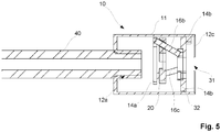
- valve device 10 according to the present invention arranged to a barrel 40 of a firearm.
- the valve device 10 will function as a sound director and/or muzzle flash damper.
- the valve device 10 comprises connection means 12a at the one end being used to attach the valve device 10 to the firearm barrel 40, i.e. forming a fastening device to the firearm barrel 40, and that the connection means 12a seals against the firearm barrel 40.
- connection means 12a This will typically be achieved by that the barrel 40 and connection means 12a are provided with corresponding threads such that the valve device 10 can be detachably attached to the barrel 40.
- a cover 12c at the other end of the valve device 10, which centrally is provided with a through hole 31 adapted for allowing a projectile fired via the firearm barrel 40 to pass.
- the bolts or rods 13a-c extending in longitudinal direction of the valve device 10, between the connection means 12a and the cover 12c, are not shown in the example.
- the aperture box 20 is movably arranged between the first 14a and second 14b stop discs and that the power gases drive the aperture box 20 in longitudinal direction from the first stop disc 14a towards the second stop disc 14b and therethrough such that the disc parts 22a-c are moved towards each other and closes.
- valve device 10 will close immediately after the projectile has passed the disc parts 22a-c and therethrough cutting/closing for powder gases and/or muzzle flash following the projectile as it leaves the barrel 40, and therethrough delay and divert the powder gases on their way out of the valve device 10.
- valve device 10 allows some gas to escape outside the closing disc, e.g. via slots or channels 32 at the outer circumference of the second stop disc 14b, and that the valve device 10 is provided with spring-functionality, as described above, such that when the gas pressure in front of the valve device 10 drops the valve device 10 gradually opens.
- spring-functionality as described above, such that when the gas pressure in front of the valve device 10 drops the valve device 10 gradually opens.
- an effective sound director and/or muzzle flash damper where powder gases/muzzle flash following a projectile is/are effectively «locked in» and delayed on their/its way out of the valve device 10.
- FIG. 6 showing a further embodiment of a valve device 10 according to the present invention where the closing mechanism is adjustable by that there is arranged an actuator mechanism 50 to the aperture box 20 capable of adjusting the aperture box 20 in longitudinal direction of the valve device 10 and therethrough determine the opening formed by the position of the disc parts 22a-c in relation to each other. In this way is enabled adjustment of the valve device 10 to a desired level/velocity of the flow of fluid, liquid or gas through the valve device 10.
- the actuator mechanism 50 is arranged to the mentioned stop discs 14a-b or bolts/rods 13a-c which can move the stop discs 14a-b/bolts/rods 13a-c in longitudinal direction of the valve device 10 and therethrough determine the opening formed by the position of the disc parts 22a-c in relation to each other.
- the actuator mechanism 50 itself can be electric or mechanic and of known type for a skilled person, which is controlled by a control unit 51 or manually.
- the control unit 51 can further be provided with various communication means and interface to known control systems and warning systems.
- the control unit 51 can further be connected to various sensor systems which can provide input for control of the actuator mechanism 50.
- the actuator mechanism 50 is a spring-based device which can be controlled such that the valve device 10 opens or closes at a certain pressure by determining the force of the spring-based actuator mechanism 50.
- a balancing valve device 10 functioning such that the pressure activates the disc parts 22a-c in larger or lesser degree depending on the pressure of the fluid, liquid or gas, and maintains the flow (of fluid, liquid or gas) at a certain level/velocity.
- the embodiment does not require a controllable actuator mechanism 50, but the actuator mechanism 50 can hold a desired spring force. The same can be achieved by arranging the actuator mechanism 50 to the stop discs 14a-b/bolts/rods 13a-c.
- stop discs 14a-b can be movably arranged in the valve device 10 with the aperture box 20 fixed, the aperture box 20 movably arranged with the stop discs 14a-b fixed, the stop discs 14a-b movably arranged to the rods/bolts 13a-b, or a combination of several of these.
- valve device 10 in a further embodiment of the valve device 10 according to the present invention the aperture box 20 is omitted such that the disc parts 22a-c via their mutual connection will be connected to the activation bolts 16a-c.
- valve device 10 can further be considered as a module-based valve device 10 where several such closing mechanisms, i.e. first 14a and second 14b stop disc, activation bolts 16a-c, possibly aperture box 20, and disc parts 22a-c, can be arranged after one another in the same tube 11 for further safety and possibly closing or opening at different pressure.
- first 14a and second 14b stop disc activation bolts 16a-c, possibly aperture box 20, and disc parts 22a-c
Landscapes
- Engineering & Computer Science (AREA)
- General Engineering & Computer Science (AREA)
- Mechanical Engineering (AREA)
- Mining & Mineral Resources (AREA)
- Life Sciences & Earth Sciences (AREA)
- Geology (AREA)
- Environmental & Geological Engineering (AREA)
- Fluid Mechanics (AREA)
- Physics & Mathematics (AREA)
- General Life Sciences & Earth Sciences (AREA)
- Geochemistry & Mineralogy (AREA)
- Sliding Valves (AREA)
- Safety Valves (AREA)
- Lift Valve (AREA)
- Crystals, And After-Treatments Of Crystals (AREA)
- Glass Compositions (AREA)
Priority Applications (3)
| Application Number | Priority Date | Filing Date | Title |
|---|---|---|---|
| RS20210760A RS62069B1 (sr) | 2015-11-04 | 2016-11-04 | Ventilski uređaj |
| PL16862530T PL3371490T3 (pl) | 2015-11-04 | 2016-11-04 | Urządzenie zaworowe |
| SI201631231T SI3371490T1 (sl) | 2015-11-04 | 2016-11-04 | Ventilna naprava |
Applications Claiming Priority (2)
| Application Number | Priority Date | Filing Date | Title |
|---|---|---|---|
| NO20151494A NO340626B1 (no) | 2015-11-04 | 2015-11-04 | Ventilinnretning |
| PCT/NO2016/050219 WO2017078541A1 (en) | 2015-11-04 | 2016-11-04 | Valve device |
Publications (3)
| Publication Number | Publication Date |
|---|---|
| EP3371490A1 EP3371490A1 (en) | 2018-09-12 |
| EP3371490A4 EP3371490A4 (en) | 2019-05-29 |
| EP3371490B1 true EP3371490B1 (en) | 2021-03-17 |
Family
ID=58662524
Family Applications (1)
| Application Number | Title | Priority Date | Filing Date |
|---|---|---|---|
| EP16862530.9A Active EP3371490B1 (en) | 2015-11-04 | 2016-11-04 | Valve device |
Country Status (12)
| Country | Link |
|---|---|
| US (1) | US10989312B2 (no) |
| EP (1) | EP3371490B1 (no) |
| BR (1) | BR112018009088A8 (no) |
| DK (1) | DK3371490T3 (no) |
| ES (1) | ES2875499T3 (no) |
| HU (1) | HUE054808T2 (no) |
| NO (1) | NO340626B1 (no) |
| PL (1) | PL3371490T3 (no) |
| PT (1) | PT3371490T (no) |
| RS (1) | RS62069B1 (no) |
| SI (1) | SI3371490T1 (no) |
| WO (1) | WO2017078541A1 (no) |
Families Citing this family (1)
| Publication number | Priority date | Publication date | Assignee | Title |
|---|---|---|---|---|
| US20230272991A1 (en) * | 2022-02-25 | 2023-08-31 | Delta P Design, Inc. | Firearm suppressor with gas-actuated valve |
Family Cites Families (9)
| Publication number | Priority date | Publication date | Assignee | Title |
|---|---|---|---|---|
| US1130609A (en) * | 1913-12-15 | 1915-03-02 | Seth T Jones | Muffler for shotguns. |
| US2934892A (en) * | 1957-01-31 | 1960-05-03 | Westinghouse Electric Corp | Variable area propulsion nozzle |
| US4460151A (en) | 1981-12-29 | 1984-07-17 | Cameron Iron Works, Inc. | Annular blowout preventer |
| US4532961A (en) * | 1982-11-22 | 1985-08-06 | Fisher Controls International, Inc. | Bidirectional disc throttling valve |
| WO1996030637A1 (en) * | 1995-03-24 | 1996-10-03 | Ultimate Power Engineering Group, Inc. | High vanadium content fuel combustor and system |
| ITBO20010154A1 (it) * | 2001-03-20 | 2002-09-20 | Azionaria Costruzioni Automati | Dispositivo erogatore per macchine riempitrici di contenitori con materia in polvere |
| DE10352372B4 (de) * | 2003-11-10 | 2011-12-08 | Interforge Klee Gmbh | Sicherheitsventil zum automatischen Absperren von Gasleitungen |
| SE0402912L (sv) * | 2004-11-30 | 2006-04-25 | Jan Norrman | Avstängningsanordning för en rörledning |
| FR3011060B1 (fr) * | 2013-09-24 | 2015-10-16 | Grdf | Dispositif de controle inserable dans une canalisation; |
-
2015
- 2015-11-04 NO NO20151494A patent/NO340626B1/no unknown
-
2016
- 2016-11-04 DK DK16862530.9T patent/DK3371490T3/da active
- 2016-11-04 ES ES16862530T patent/ES2875499T3/es active Active
- 2016-11-04 US US15/773,682 patent/US10989312B2/en active Active
- 2016-11-04 EP EP16862530.9A patent/EP3371490B1/en active Active
- 2016-11-04 PL PL16862530T patent/PL3371490T3/pl unknown
- 2016-11-04 WO PCT/NO2016/050219 patent/WO2017078541A1/en active Application Filing
- 2016-11-04 PT PT168625309T patent/PT3371490T/pt unknown
- 2016-11-04 BR BR112018009088A patent/BR112018009088A8/pt not_active Application Discontinuation
- 2016-11-04 SI SI201631231T patent/SI3371490T1/sl unknown
- 2016-11-04 HU HUE16862530A patent/HUE054808T2/hu unknown
- 2016-11-04 RS RS20210760A patent/RS62069B1/sr unknown
Non-Patent Citations (1)
| Title |
|---|
| None * |
Also Published As
| Publication number | Publication date |
|---|---|
| EP3371490A1 (en) | 2018-09-12 |
| PT3371490T (pt) | 2021-06-22 |
| EP3371490A4 (en) | 2019-05-29 |
| BR112018009088A2 (pt) | 2018-10-30 |
| BR112018009088A8 (pt) | 2019-02-26 |
| NO340626B1 (no) | 2017-05-15 |
| WO2017078541A1 (en) | 2017-05-11 |
| NO20151494A1 (no) | 2017-05-05 |
| US10989312B2 (en) | 2021-04-27 |
| US20180328497A1 (en) | 2018-11-15 |
| ES2875499T3 (es) | 2021-11-10 |
| PL3371490T3 (pl) | 2021-10-18 |
| RS62069B1 (sr) | 2021-07-30 |
| DK3371490T3 (da) | 2021-06-21 |
| SI3371490T1 (sl) | 2021-08-31 |
| HUE054808T2 (hu) | 2021-10-28 |
Similar Documents
| Publication | Publication Date | Title |
|---|---|---|
| US9969233B2 (en) | Mechanical actuator with a hydraulic damper device | |
| EP3371490B1 (en) | Valve device | |
| US20180180377A1 (en) | High Pressure Air System for Airsoft Gun | |
| RU2553482C1 (ru) | Тормоз отката артиллерийского орудия | |
| AU2021269280A1 (en) | Safety device regulator | |
| US20080099713A1 (en) | Ejector valve machine | |
| CN106195097A (zh) | 一种驻退复进二合一缓冲阻尼装置 | |
| KR102167502B1 (ko) | 스로틀 기능을 구비한 체크밸브 | |
| WO2020051095A3 (en) | Statorless shear valve pulse generator | |
| KR101959187B1 (ko) | 유압 버퍼 조립체 | |
| US880386A (en) | Silent firearm. | |
| US9303660B2 (en) | Valves with metering sleeves | |
| DE102007038638B3 (de) | Düseneinsatz | |
| US9417031B2 (en) | Device for controlling the impulsive feeding of a pressurized fluid and an air weapon comprising such device | |
| KR102352385B1 (ko) | 차단 메커니즘이 있는 공압식 펄스 공구 | |
| US8016263B2 (en) | Ejector valve machine | |
| US20190168039A1 (en) | Air-pressure controlled piston and valve configuration | |
| US8307847B2 (en) | Ejector valve with glands | |
| EP3227590B1 (en) | Valve arrangement | |
| EP3521653A1 (en) | Gas spring comprising a safety device | |
| US993003A (en) | Hydraulic brake for guns having recoiling barrels. | |
| WO2005110709A1 (en) | Screw tip and molding system apparatus | |
| IT201800004097A1 (it) | Dispositivo di valvola | |
| WO2017098032A3 (en) | Method and device for flow control |
Legal Events
| Date | Code | Title | Description |
|---|---|---|---|
| STAA | Information on the status of an ep patent application or granted ep patent |
Free format text: STATUS: THE INTERNATIONAL PUBLICATION HAS BEEN MADE |
|
| PUAI | Public reference made under article 153(3) epc to a published international application that has entered the european phase |
Free format text: ORIGINAL CODE: 0009012 |
|
| STAA | Information on the status of an ep patent application or granted ep patent |
Free format text: STATUS: REQUEST FOR EXAMINATION WAS MADE |
|
| 17P | Request for examination filed |
Effective date: 20180604 |
|
| AK | Designated contracting states |
Kind code of ref document: A1 Designated state(s): AL AT BE BG CH CY CZ DE DK EE ES FI FR GB GR HR HU IE IS IT LI LT LU LV MC MK MT NL NO PL PT RO RS SE SI SK SM TR |
|
| AX | Request for extension of the european patent |
Extension state: BA ME |
|
| DAV | Request for validation of the european patent (deleted) | ||
| DAX | Request for extension of the european patent (deleted) | ||
| A4 | Supplementary search report drawn up and despatched |
Effective date: 20190429 |
|
| RIC1 | Information provided on ipc code assigned before grant |
Ipc: F41A 21/34 20060101ALI20190423BHEP Ipc: F41A 21/30 20060101ALI20190423BHEP Ipc: F16K 3/06 20060101ALI20190423BHEP Ipc: F16K 3/03 20060101AFI20190423BHEP Ipc: F16K 3/18 20060101ALI20190423BHEP |
|
| GRAP | Despatch of communication of intention to grant a patent |
Free format text: ORIGINAL CODE: EPIDOSNIGR1 |
|
| STAA | Information on the status of an ep patent application or granted ep patent |
Free format text: STATUS: GRANT OF PATENT IS INTENDED |
|
| INTG | Intention to grant announced |
Effective date: 20201007 |
|
| RAP1 | Party data changed (applicant data changed or rights of an application transferred) |
Owner name: GROETTE, CAMILLA |
|
| RIN1 | Information on inventor provided before grant (corrected) |
Inventor name: ROEST, BERNT ERIK |
|
| GRAS | Grant fee paid |
Free format text: ORIGINAL CODE: EPIDOSNIGR3 |
|
| GRAA | (expected) grant |
Free format text: ORIGINAL CODE: 0009210 |
|
| STAA | Information on the status of an ep patent application or granted ep patent |
Free format text: STATUS: THE PATENT HAS BEEN GRANTED |
|
| AK | Designated contracting states |
Kind code of ref document: B1 Designated state(s): AL AT BE BG CH CY CZ DE DK EE ES FI FR GB GR HR HU IE IS IT LI LT LU LV MC MK MT NL NO PL PT RO RS SE SI SK SM TR |
|
| REG | Reference to a national code |
Ref country code: GB Ref legal event code: FG4D |
|
| REG | Reference to a national code |
Ref country code: CH Ref legal event code: EP |
|
| REG | Reference to a national code |
Ref country code: DE Ref legal event code: R096 Ref document number: 602016054601 Country of ref document: DE |
|
| REG | Reference to a national code |
Ref country code: IE Ref legal event code: FG4D |
|
| REG | Reference to a national code |
Ref country code: AT Ref legal event code: REF Ref document number: 1372551 Country of ref document: AT Kind code of ref document: T Effective date: 20210415 |
|
| REG | Reference to a national code |
Ref country code: RO Ref legal event code: EPE Ref country code: FI Ref legal event code: FGE |
|
| REG | Reference to a national code |
Ref country code: DE Ref legal event code: R081 Ref document number: 602016054601 Country of ref document: DE Owner name: URSUS INVEST AS, NO Free format text: FORMER OWNER: GROETTE, CAMILLA, TRONDHEIM, NO |
|
| REG | Reference to a national code |
Ref country code: DK Ref legal event code: T3 Effective date: 20210614 |
|
| REG | Reference to a national code |
Ref country code: PT Ref legal event code: SC4A Ref document number: 3371490 Country of ref document: PT Date of ref document: 20210622 Kind code of ref document: T Free format text: AVAILABILITY OF NATIONAL TRANSLATION Effective date: 20210616 |
|
| REG | Reference to a national code |
Ref country code: NL Ref legal event code: FP |
|
| REG | Reference to a national code |
Ref country code: SE Ref legal event code: TRGR |
|
| REG | Reference to a national code |
Ref country code: NL Ref legal event code: PD Owner name: URSUS INVEST AS; NO Free format text: DETAILS ASSIGNMENT: CHANGE OF OWNER(S), ASSIGNMENT; FORMER OWNER NAME: GROETTE, CAMILLA Effective date: 20210616 |
|
| RAP2 | Party data changed (patent owner data changed or rights of a patent transferred) |
Owner name: URSUS INVEST AS |
|
| REG | Reference to a national code |
Ref country code: LT Ref legal event code: MG9D |
|
| REG | Reference to a national code |
Ref country code: SK Ref legal event code: T3 Ref document number: E 37368 Country of ref document: SK |
|
| PG25 | Lapsed in a contracting state [announced via postgrant information from national office to epo] |
Ref country code: GR Free format text: LAPSE BECAUSE OF FAILURE TO SUBMIT A TRANSLATION OF THE DESCRIPTION OR TO PAY THE FEE WITHIN THE PRESCRIBED TIME-LIMIT Effective date: 20210618 Ref country code: HR Free format text: LAPSE BECAUSE OF FAILURE TO SUBMIT A TRANSLATION OF THE DESCRIPTION OR TO PAY THE FEE WITHIN THE PRESCRIBED TIME-LIMIT Effective date: 20210317 |
|
| REG | Reference to a national code |
Ref country code: GB Ref legal event code: 732E Free format text: REGISTERED BETWEEN 20210715 AND 20210721 |
|
| REG | Reference to a national code |
Ref country code: NO Ref legal event code: T2 Effective date: 20210317 |
|
| PG25 | Lapsed in a contracting state [announced via postgrant information from national office to epo] |
Ref country code: LV Free format text: LAPSE BECAUSE OF FAILURE TO SUBMIT A TRANSLATION OF THE DESCRIPTION OR TO PAY THE FEE WITHIN THE PRESCRIBED TIME-LIMIT Effective date: 20210317 |
|
| REG | Reference to a national code |
Ref country code: AT Ref legal event code: PC Ref document number: 1372551 Country of ref document: AT Kind code of ref document: T Owner name: URSUS INVEST AS, NO Effective date: 20210719 |
|
| REG | Reference to a national code |
Ref country code: BE Ref legal event code: PD Owner name: URSUS INVEST AS; NO Free format text: DETAILS ASSIGNMENT: CHANGE OF OWNER(S), ASSIGNMENT; FORMER OWNER NAME: GROETTE, CAMILLA Effective date: 20210615 |
|
| REG | Reference to a national code |
Ref country code: HU Ref legal event code: AG4A Ref document number: E054808 Country of ref document: HU |
|
| PG25 | Lapsed in a contracting state [announced via postgrant information from national office to epo] |
Ref country code: SM Free format text: LAPSE BECAUSE OF FAILURE TO SUBMIT A TRANSLATION OF THE DESCRIPTION OR TO PAY THE FEE WITHIN THE PRESCRIBED TIME-LIMIT Effective date: 20210317 Ref country code: EE Free format text: LAPSE BECAUSE OF FAILURE TO SUBMIT A TRANSLATION OF THE DESCRIPTION OR TO PAY THE FEE WITHIN THE PRESCRIBED TIME-LIMIT Effective date: 20210317 Ref country code: LT Free format text: LAPSE BECAUSE OF FAILURE TO SUBMIT A TRANSLATION OF THE DESCRIPTION OR TO PAY THE FEE WITHIN THE PRESCRIBED TIME-LIMIT Effective date: 20210317 |
|
| REG | Reference to a national code |
Ref country code: ES Ref legal event code: FG2A Ref document number: 2875499 Country of ref document: ES Kind code of ref document: T3 Effective date: 20211110 |
|
| REG | Reference to a national code |
Ref country code: DE Ref legal event code: R097 Ref document number: 602016054601 Country of ref document: DE |
|
| REG | Reference to a national code |
Ref country code: AT Ref legal event code: UEP Ref document number: 1372551 Country of ref document: AT Kind code of ref document: T Effective date: 20210317 |
|
| PLBE | No opposition filed within time limit |
Free format text: ORIGINAL CODE: 0009261 |
|
| STAA | Information on the status of an ep patent application or granted ep patent |
Free format text: STATUS: NO OPPOSITION FILED WITHIN TIME LIMIT |
|
| PG25 | Lapsed in a contracting state [announced via postgrant information from national office to epo] |
Ref country code: AL Free format text: LAPSE BECAUSE OF FAILURE TO SUBMIT A TRANSLATION OF THE DESCRIPTION OR TO PAY THE FEE WITHIN THE PRESCRIBED TIME-LIMIT Effective date: 20210317 |
|
| 26N | No opposition filed |
Effective date: 20211220 |
|
| PG25 | Lapsed in a contracting state [announced via postgrant information from national office to epo] |
Ref country code: MC Free format text: LAPSE BECAUSE OF FAILURE TO SUBMIT A TRANSLATION OF THE DESCRIPTION OR TO PAY THE FEE WITHIN THE PRESCRIBED TIME-LIMIT Effective date: 20210317 |
|
| PG25 | Lapsed in a contracting state [announced via postgrant information from national office to epo] |
Ref country code: LU Free format text: LAPSE BECAUSE OF NON-PAYMENT OF DUE FEES Effective date: 20211104 |
|
| PG25 | Lapsed in a contracting state [announced via postgrant information from national office to epo] |
Ref country code: CY Free format text: LAPSE BECAUSE OF FAILURE TO SUBMIT A TRANSLATION OF THE DESCRIPTION OR TO PAY THE FEE WITHIN THE PRESCRIBED TIME-LIMIT Effective date: 20210317 |
|
| P01 | Opt-out of the competence of the unified patent court (upc) registered |
Effective date: 20230526 |
|
| PGFP | Annual fee paid to national office [announced via postgrant information from national office to epo] |
Ref country code: NL Payment date: 20231120 Year of fee payment: 8 |
|
| PGFP | Annual fee paid to national office [announced via postgrant information from national office to epo] |
Ref country code: SK Payment date: 20231031 Year of fee payment: 8 |
|
| PGFP | Annual fee paid to national office [announced via postgrant information from national office to epo] |
Ref country code: GB Payment date: 20231123 Year of fee payment: 8 |
|
| PGFP | Annual fee paid to national office [announced via postgrant information from national office to epo] |
Ref country code: IS Payment date: 20231110 Year of fee payment: 8 |
|
| PGFP | Annual fee paid to national office [announced via postgrant information from national office to epo] |
Ref country code: TR Payment date: 20231102 Year of fee payment: 8 Ref country code: SI Payment date: 20231026 Year of fee payment: 8 Ref country code: SE Payment date: 20231120 Year of fee payment: 8 Ref country code: RS Payment date: 20231027 Year of fee payment: 8 Ref country code: RO Payment date: 20231101 Year of fee payment: 8 Ref country code: PT Payment date: 20231026 Year of fee payment: 8 Ref country code: NO Payment date: 20231127 Year of fee payment: 8 Ref country code: IT Payment date: 20231124 Year of fee payment: 8 Ref country code: IE Payment date: 20231121 Year of fee payment: 8 Ref country code: HU Payment date: 20231122 Year of fee payment: 8 Ref country code: FR Payment date: 20231120 Year of fee payment: 8 Ref country code: FI Payment date: 20231121 Year of fee payment: 8 Ref country code: DK Payment date: 20231124 Year of fee payment: 8 Ref country code: DE Payment date: 20231121 Year of fee payment: 8 Ref country code: CZ Payment date: 20231030 Year of fee payment: 8 Ref country code: CH Payment date: 20231202 Year of fee payment: 8 Ref country code: BG Payment date: 20231120 Year of fee payment: 8 Ref country code: AT Payment date: 20231121 Year of fee payment: 8 |
|
| PGFP | Annual fee paid to national office [announced via postgrant information from national office to epo] |
Ref country code: PL Payment date: 20231019 Year of fee payment: 8 Ref country code: BE Payment date: 20231120 Year of fee payment: 8 |
|
| PGFP | Annual fee paid to national office [announced via postgrant information from national office to epo] |
Ref country code: ES Payment date: 20240129 Year of fee payment: 8 |
|
| PG25 | Lapsed in a contracting state [announced via postgrant information from national office to epo] |
Ref country code: MK Free format text: LAPSE BECAUSE OF FAILURE TO SUBMIT A TRANSLATION OF THE DESCRIPTION OR TO PAY THE FEE WITHIN THE PRESCRIBED TIME-LIMIT Effective date: 20210317 |