EP3371348B1 - Kathodischer korrosionsschutz - Google Patents
Kathodischer korrosionsschutz Download PDFInfo
- Publication number
- EP3371348B1 EP3371348B1 EP16861147.3A EP16861147A EP3371348B1 EP 3371348 B1 EP3371348 B1 EP 3371348B1 EP 16861147 A EP16861147 A EP 16861147A EP 3371348 B1 EP3371348 B1 EP 3371348B1
- Authority
- EP
- European Patent Office
- Prior art keywords
- anode
- storage component
- sacrificial anode
- battery
- steel
- Prior art date
- Legal status (The legal status is an assumption and is not a legal conclusion. Google has not performed a legal analysis and makes no representation as to the accuracy of the status listed.)
- Active
Links
Images


Classifications
-
- C—CHEMISTRY; METALLURGY
- C23—COATING METALLIC MATERIAL; COATING MATERIAL WITH METALLIC MATERIAL; CHEMICAL SURFACE TREATMENT; DIFFUSION TREATMENT OF METALLIC MATERIAL; COATING BY VACUUM EVAPORATION, BY SPUTTERING, BY ION IMPLANTATION OR BY CHEMICAL VAPOUR DEPOSITION, IN GENERAL; INHIBITING CORROSION OF METALLIC MATERIAL OR INCRUSTATION IN GENERAL
- C23F—NON-MECHANICAL REMOVAL OF METALLIC MATERIAL FROM SURFACE; INHIBITING CORROSION OF METALLIC MATERIAL OR INCRUSTATION IN GENERAL; MULTI-STEP PROCESSES FOR SURFACE TREATMENT OF METALLIC MATERIAL INVOLVING AT LEAST ONE PROCESS PROVIDED FOR IN CLASS C23 AND AT LEAST ONE PROCESS COVERED BY SUBCLASS C21D OR C22F OR CLASS C25
- C23F13/00—Inhibiting corrosion of metals by anodic or cathodic protection
- C23F13/02—Inhibiting corrosion of metals by anodic or cathodic protection cathodic; Selection of conditions, parameters or procedures for cathodic protection, e.g. of electrical conditions
- C23F13/06—Constructional parts, or assemblies of cathodic-protection apparatus
- C23F13/08—Electrodes specially adapted for inhibiting corrosion by cathodic protection; Manufacture thereof; Conducting electric current thereto
- C23F13/20—Conducting electric current to electrodes
-
- C—CHEMISTRY; METALLURGY
- C23—COATING METALLIC MATERIAL; COATING MATERIAL WITH METALLIC MATERIAL; CHEMICAL SURFACE TREATMENT; DIFFUSION TREATMENT OF METALLIC MATERIAL; COATING BY VACUUM EVAPORATION, BY SPUTTERING, BY ION IMPLANTATION OR BY CHEMICAL VAPOUR DEPOSITION, IN GENERAL; INHIBITING CORROSION OF METALLIC MATERIAL OR INCRUSTATION IN GENERAL
- C23F—NON-MECHANICAL REMOVAL OF METALLIC MATERIAL FROM SURFACE; INHIBITING CORROSION OF METALLIC MATERIAL OR INCRUSTATION IN GENERAL; MULTI-STEP PROCESSES FOR SURFACE TREATMENT OF METALLIC MATERIAL INVOLVING AT LEAST ONE PROCESS PROVIDED FOR IN CLASS C23 AND AT LEAST ONE PROCESS COVERED BY SUBCLASS C21D OR C22F OR CLASS C25
- C23F13/00—Inhibiting corrosion of metals by anodic or cathodic protection
- C23F13/02—Inhibiting corrosion of metals by anodic or cathodic protection cathodic; Selection of conditions, parameters or procedures for cathodic protection, e.g. of electrical conditions
- C23F13/06—Constructional parts, or assemblies of cathodic-protection apparatus
-
- C—CHEMISTRY; METALLURGY
- C23—COATING METALLIC MATERIAL; COATING MATERIAL WITH METALLIC MATERIAL; CHEMICAL SURFACE TREATMENT; DIFFUSION TREATMENT OF METALLIC MATERIAL; COATING BY VACUUM EVAPORATION, BY SPUTTERING, BY ION IMPLANTATION OR BY CHEMICAL VAPOUR DEPOSITION, IN GENERAL; INHIBITING CORROSION OF METALLIC MATERIAL OR INCRUSTATION IN GENERAL
- C23F—NON-MECHANICAL REMOVAL OF METALLIC MATERIAL FROM SURFACE; INHIBITING CORROSION OF METALLIC MATERIAL OR INCRUSTATION IN GENERAL; MULTI-STEP PROCESSES FOR SURFACE TREATMENT OF METALLIC MATERIAL INVOLVING AT LEAST ONE PROCESS PROVIDED FOR IN CLASS C23 AND AT LEAST ONE PROCESS COVERED BY SUBCLASS C21D OR C22F OR CLASS C25
- C23F2201/00—Type of materials to be protected by cathodic protection
- C23F2201/02—Concrete, e.g. reinforced
-
- C—CHEMISTRY; METALLURGY
- C23—COATING METALLIC MATERIAL; COATING MATERIAL WITH METALLIC MATERIAL; CHEMICAL SURFACE TREATMENT; DIFFUSION TREATMENT OF METALLIC MATERIAL; COATING BY VACUUM EVAPORATION, BY SPUTTERING, BY ION IMPLANTATION OR BY CHEMICAL VAPOUR DEPOSITION, IN GENERAL; INHIBITING CORROSION OF METALLIC MATERIAL OR INCRUSTATION IN GENERAL
- C23F—NON-MECHANICAL REMOVAL OF METALLIC MATERIAL FROM SURFACE; INHIBITING CORROSION OF METALLIC MATERIAL OR INCRUSTATION IN GENERAL; MULTI-STEP PROCESSES FOR SURFACE TREATMENT OF METALLIC MATERIAL INVOLVING AT LEAST ONE PROCESS PROVIDED FOR IN CLASS C23 AND AT LEAST ONE PROCESS COVERED BY SUBCLASS C21D OR C22F OR CLASS C25
- C23F2213/00—Aspects of inhibiting corrosion of metals by anodic or cathodic protection
- C23F2213/20—Constructional parts or assemblies of the anodic or cathodic protection apparatus
- C23F2213/21—Constructional parts or assemblies of the anodic or cathodic protection apparatus combining at least two types of anodic or cathodic protection
Definitions
- This invention relates to a method for cathodically protecting and/or passivating a metal section in an ionically conductive material and to an assembly for cathodically protecting and/or passivating a steel metal section in an ionically conductive material.
- Impressed current systems using a battery are known. Such impressed current systems can use other types of power supply including common rectifiers which rectify an AC voltage from a suitable source into a required DC voltage for the impressed current between the anode and the steel. It is also known to provide solar panels to be used in a system of this type.
- galvanic systems can be used which avoid necessity for any power supply since the voltage between the steel and the anode is provided by selecting a suitable material for the anode which is sufficiently electro-negative to ensure that a current is generated to provide corrosion protection.
- the first relates to the mass of zinc per anode which, depending on the required current output, limits the useful life of the anode.
- the second is the actual current output of the anode which may or may not be sufficient to halt corrosion of the steel.
- the current output is limited by the driving voltage, which is essentially a fixed property and varies with exposure conditions, age of the anode, and build-up of corrosion products over time.
- a method for cathodically protecting and/or passivating a metal section in an ionically conductive material the method being as defined by claim 1.
- the method comprises: providing a non-sacrificial anode for communication of an electrical current to the metal section in the ionically conductive material where the non-sacrificial anode is of a material which is not sacrificial to the metal section; providing a storage component of electrical energy with two poles for communicating electrical current generated by release of the electrical energy; wherein the storage component is contained within an outer casing having an exterior surface; electrically connecting one pole to the metal section, electrically connecting the other pole to the non-sacrificial anode and placing the non-sacrificial anode in ionic contact with the ionically conductive material such that the electrical current can flow from the storage component through the electrical connection to the metal section thus reducing a total amount of electrical energy contained in the storage component; wherein the non-sacrificial anode
- an assembly for cathodically protecting and/or passivating a steel metal section in an ionically conductive material the assembly being as defined by claim 11.
- the assembly comprises: a non-sacrificial anode of a material which is not sacrificial to steel; a storage component of electrical energy with two poles for communicating electrical current generated by release of the electrical energy; wherein the storage component is contained within an outer casing having an exterior surface; an arrangement for electrically connecting one pole to the metal section; an arrangement for electrically connecting the other pole to the non-sacrificial anode; the assembly being arranged for placing the non-sacrificial anode in ionic contact with the ionically conductive material such that electrons can flow from the storage component through the electrical connecting arrangement to the metal section; wherein the non-sacrificial anode is defined on the exterior surface of the outer casing so that the storage component is connected as a single unit with the non-sacrificial anode.
- the arrangement herein can be used where the anode is in the form of a plurality of associated anodes all connected to a cell or a battery of cells.
- the storage component as defined above can be a cell or battery or battery of cells / batteries or it can be a capacitor or a supercapacitor or ultracapacitor which provides a system for storing charge different from conventional electrolytic cells or batteries.
- a supercapacitor is a high-capacity electrochemical capacitor with capacitance values much higher than other capacitors. These capacitors typically have lower voltage limits than standard or conventional capacitors. They typically store 10 to 100 times more energy per unit volume or mass than standard capacitors, can accept and deliver charge much faster than batteries, and tolerate many more charge and discharge cycles than rechargeable batteries.
- Supercapacitors do not use the conventional solid dielectric of standard capacitors. They use electrostatic double-layer capacitance or electrochemical pseudo-capacitance or a combination of both instead.
- Electrostatic double-layer capacitors use carbon electrodes or derivatives with much higher electrostatic double-layer capacitance than electrochemical pseudo-capacitance, achieving separation of charge in a Helmholtz double layer at the interface between the surface of a conductive electrode and an electrolyte.
- the separation of charge is of the order of a few ⁇ ngströms (0.3-0.8 nm), much smaller than in a conventional capacitor.
- Supercapacitors are a great advancement on normal capacitors being capable of storing a high charge once fully charged.
- the capacity of a 2.7V 200F supercapacitor is capable of holding a charge of the order of over 500C (A x seconds).
- Typical cathodic protection systems require around 170 to 400C/m 2 of steel per day so such a capacitor is able to provide, when fully charged, enough charge to protect 1m 2 or more of steel for a day. This represents 2-5mA/m 2 current density. In order for example to double this figure then we need to double the capacitance to around 400 F.
- a system utilising supercapacitors of this size spaced at intervals to provide current for 1m 2 or more of steel can be an effective cathodic protection system.
- Daily recharging can easily be provided by solar panels, for example, but other means of producing reasonably regular bursts of current could be used as charging components for the supercapacitors.
- An example of such could be piezoelectric materials which can be incorporated in roads, parking garages, bridges, runways etc. enabling current to be generated by loading and / or movement of the structure or vehicles passing over them.
- piezoelectric materials could be used to generate electricity to power an impressed current system directly, or to charge / recharge batteries or capacitors / supercapacitors.
- High current output is required from the storage component such as a battery.
- one pole is connected to the metal section to be protected. Electrons flow from the storage component to the metal section such that corrosion of the metal section is reduced.
- the other pole is connected to the non-sacrificial anode, which the claimed invention requires to be defined on the exterior surface of the outer casing of the storage component.
- the polarity of the battery is such that the case of the battery, if it is made of a suitable material will act as the anode and will be able to distribute the necessary current through the ionically conductive material such as mortar or concrete.
- the non-sacrificial anode may encase or coat the whole exterior surface of the outer casing of the storage component such as a battery or capacitor.
- Anodes can be made of any inert conductive material such as MMO coated titanium or other noble metal or sub-metal, conductive coating, conductive ceramic material etc. and can be embedded in an alkaline mortar or an inert material such as sand which may be dosed with an alkali solution.
- Stainless steel can also be a suitable current carrier when embedded in mortar or compacted sand dosed with alkali such as a saturated solution of lithium hydroxide.
- the storage component is initially charged or is subsequently re-charged while in situ that is while in contact with the ionically conductive material.
- the arrangement may include or preferably includes automatic switching systems to effect the periodic charging process.
- the storage component can be charged by a solar cell or by an outside power source such as a second battery or a power supply.
- a system which operates to subsequently automatically and repeatedly or periodically carry out the re-charge.
- the storage component is subsequently re-charged by a recharging power supply which is an integral unit with the anode and the storage component.
- a recharging power supply which is an integral unit with the anode and the storage component.
- the system also may operate as a periodic maintenance programme where a power supply is brought into operation periodically as required to effect the re-charging of an anode assembly or a set of anode assemblies in a structure.
- the storage component is subsequently re-charged by applying voltage directly between both terminals or between a first connection to a terminal of the storage component and a second connection to the metal section.
- the claimed invention requires that the storage component is contained within an outer casing having an exterior surface, and that the non-sacrificial anode is defined on the exterior surface of the outer casing so that the storage component is connected as a common single unit with the non-sacrificial anode.
- the storage component is connected to the metal section and is charged, in an initial charging step or in a subsequent re-charging, after installation by a connection to the one terminal and a second connection to the metal section.
- This method of connection acts to pass extra current to the metal section during the charging or re-charging step to passivate the metal section or reduce future current requirement to maintain passivity or mitigate corrosion of the metal section.
- the method of the claimed invention requires placing the non-sacrificial anode in ionic communication with the ionically conductive material.
- the common single unit comprising the storage component and the anode or anodes is at least partly buried in the ionically conductive material.
- application to the surface or other modes of mounting where the anode is in ionic contact with the material can be used.
- the storage component comprises a cell with an outer case wherein the case is fully or partially formed of the anode material so that the anode is formed by the outer case either by an outer surface of the same material or as a coating or layer on the exterior of the case.
- the anode forms directly the outer case of the cell where the case contains and houses the cathode material of the cell the electrolyte, the anode material and other components of the cell. That is, in this embodiment, the anode is defined by a layer or coating on the outer (i.e. exterior) surface of the outer casing of the storage component itself or actually as the outer surface of the outer casing of the storage component and not as an additional element which is separate from the casing of the storage component.
- the anode material may cover the whole surface or may be a partial covering leaving other areas exposed.
- the above features can be preferably used for protection of steel reinforcing or structural members in concrete or mortar material where it is well known that corrosion can cause breakdown of the concrete due to the expansive forces of the corrosion products and due to the reduction to the steel strength. However, uses in other situations can arise.
- impressed current anode used herein is intended to distinguish from a sacrificial anode where the sacrificial anode is formed of a material, typically of zinc, which is less noble than the metal section so that it preferentially corrodes relative to the metal section to be protected.
- the impressed current anode is one which is used in conjunction with an external power supply and does not need to be less noble than the metal section.
- Such impressed current anodes are formed of titanium, platinum, niobium, carbon and other noble metals and oxides which do not corrode readily.
- the assembly and methods disclosed herein are preferably designed for use where the metal section is steel and the ionically conductive material is concrete or mortar.
- the power supply may include a solar panel which drives the impressed current anode and rechargeable galvanic anode so as to provide long term protection when the solar power is on and off.
- the construction and methods proposed herein are designed particularly where the metal section is steel and the ionically conductive material is concrete or mortar. However the same arrangements may be used in other corrosion protection systems such as for pipes or other constructions in soil, and in many other systems where such anodes can be used.
- the assembly includes a reinforcing layer, such as disclosed in US Patent 7,226,532 issued June 5 2007 to Whitmore, to which reference may be made for further details not disclosed herein, to restrain and resist forces such as expansion, contraction and deformation forces which may be caused by corrosion of the anodes, deposition of sacrificial anode ions and other physical / environmental forces such as freezing, thawing, wetting, drying and thermal expansion / contraction.
- a reinforcing layer such as disclosed in US Patent 7,226,532 issued June 5 2007 to Whitmore, to which reference may be made for further details not disclosed herein, to restrain and resist forces such as expansion, contraction and deformation forces which may be caused by corrosion of the anodes, deposition of sacrificial anode ions and other physical / environmental forces such as freezing, thawing, wetting, drying and thermal expansion / contraction.
- a typical alkaline manganese dioxide-zinc rechargeable cell comprises the following main units: a steel can 12 defining a cylindrical inner space, a manganese dioxide cathode 14 formed by a plurality of hollow cylindrical pellets 16 pressed in the can 12, a zinc anode 18 made of an anode gel and arranged in the hollow interior of the cathode 14, and a cylindrical separator 20 separating the anode 18 from the cathode 14.
- the ionic conductivity (electrolyte) between the anode and the cathode is provided by the presence of potassium hydroxide, KOH, electrolyte added into the cell in a predetermined quantity.
- rechargeable cells comprise similar main components (can, cathode, anode, separator and electrolyte) but the composition of the components may differ. Some of the types of cell may however be of a different construction such as lead/acid cells or lithium cells.
- the can 12 is closed at the bottom, and it has a central circular pip 22 serving as the positive terminal.
- the upper end of the can 12 is hermetically sealed by a cell closure assembly which comprises a negative cap 24 formed by a thin metal sheet, a current collector nail 26 attached to the negative cap 24 and penetrating deeply into the anode gel to provide electrical contact with the anode, and a plastic top 28 electrically insulating the negative cap 24 from the can 12 and separating gas spaces formed beyond the cathode and anode structures, respectively.
- the material of separator 20 consists of two different materials, i.e.: a first material 30 made of fibrous sheet material wettable by the electrolyte, and a second material 32 being impermeable to small particles but retaining ionic permeability.
- An expedient material for the first layer is a sheet material of non-woven polyamide fiber, which is absorbent and serves as a reservoir for electrolyte.
- the macro-porous structure of the absorbent layer cannot prevent internal shorting by zinc dendrites or deposits during discharge/charge cycling.
- the second 32 material which may be a layer or layers of micro-porous or non-porous material which may be laminated to or coated onto the fibrous sheet material.
- One suitable material is one or more cellophane membranes laminated to the non-woven polyamide sheet.
- Another is one or more coatings of regenerated cellulose or viscose coated onto and partially impregnating the non-woven polyamide sheet, resulting in a composite material.
- the cell therefore includes a first terminal 42 and a second terminal 43 defined by the outer casing 12.
- the first terminal 42 is connected to the pin or nail 26 which is engaged into the anode material 18.
- the terminal 42 connects to a connecting wire 42A which extends from the anode material 18 for connection to the steel reinforcing bar 40, as shown in figure 2 .
- the pin 26 and the wire 42A together with the terminal 42 may all form an integral structure where the wire extends into the anode material in the form of the pin 26 or is sufficiently welded, soldered, clamped or otherwise electrically connected. This is to ensure an effective connection between the wire 42A and the anode material 18.
- anode 44 is applied as a coating onto the casing 12 of the cell.
- the anode 44 is of an inert material so that it is more noble than steel. Examples of such materials are well known. Thus the anode material 44 does not corrode or significantly corrode during the cathodic protection process.
- the terminal 42 is connected to the steel reinforcement 40 by the wire 42A.
- the wire may comprise steel, copper, brass or titanium.
- the wire may comprise a layer of a second metal or alloy or a layer of insulation.
- the second terminal defined by the casing is connected to the anode by the contiguous surface therebetween. As shown in figure 2 , the anode 44 is placed in contact with the ionically conductive material or concrete 41 so that electrons can flow from the cell through the electrical connector 43 to the metal section 40.
- Anode 44 may comprise one or more layers and may include a mixed metal oxide (MMO), catalytic or sub-oxide layer.
- MMO mixed metal oxide
- the anode is formed of an inert material which does not corrode in the protection process
- the anode and the cell contained therein can be directly incorporated or buried in to the concrete or other ionically conductive material without the necessity for an intervening encapsulating material such as a porous mortar matrix.
- an intervening encapsulating material such as a porous mortar matrix.
- any inert anode during operation generates acid (or consumes alkali) it is beneficial for the anode to be buried in an alkaline material such as concrete or high alkalinity mortar to prevent material near the anode from becoming acidic. If desired, additional alkali may be added to the concrete or other material the anode is in contact with.
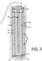
- FIG 3 there is shown an alternative arrangement where the same cell is connected to and uses an anode 46 formed of a sacrificial material such as zinc.
- anode 46 formed of a sacrificial material such as zinc.
- the anode is applied as a coating onto the outside surface of the casing.
- a porous or reinforced matrix 47 which is arranged to absorb any expansive forces caused by the corrosion of the sacrificial anode 46 and which may contain activators of a conventional construction for ensuring continued corrosion of the sacrificial material.
- the casing 12 is formed of a suitable inert material more noble than steel and thus there is an inert anode 44 defined by the casing.
- the sacrificial material of the anode 46 is formed as a thin coating or a separate body which corrodes away after a relatively short period of time, leaving the inert anode 44 defined by the casing to continue further cathodic protection.
- the inert anode defined by the casing is collated with or in electrical contact with the body of the sacrificial anode material 46 and the anode material acts to provide an initial boost of current until the sacrificial anode material is consumed, following which the further cathodic protection is obtained by the current discharge through the inert anode defined by the casing 12.
- FIG 4 is shown a further embodiment which uses the inert anode 44 but provides an interior supply 48 of solid zinc within the cell so as to ensure longevity of operation due to the presence of sufficient zinc and cathode material within the system to maintain the current flow from the cell through the anode 44 and through the terminal 42 to ensure the cathodic protection of the steel 40.
- the zinc may be cast rolled, pressed or otherwise formed.
- FIG 5 there is shown a system for recharging the batteries or cells of the type shown in figure 1 .
- the combination forming the anode assembly can be formed by a single cell where the casing of the cell directly surrounds the cell and is directly attached to the anode.
- the current is supplied by a battery 49 defined by separate cells 49A, 49B and 49C.
- the cells can be constructed in any suitable arrangement and the assembly into a battery is shown only schematically in figure 5 .
- the construction includes the non-sacrificial anode 44 which is located on an exterior casing of the battery 49.
- the battery includes the first terminal 42 and the second terminal 43.
- a recharging system 50 is provided which can be used to recharge each of the batteries 49.
- the recharging system 50 can comprise a conventional rectifier type power source generating a suitable voltage output for connection across the batteries.
- a solar source 51 can be used to generate electrical power which is controlled by the charger 50 to be applied to the batteries 50.
- Each of the cells is constructed in a manner which allows the cell to be recharged.
- Such rechargeable cells are of course well-known and their construction is available from many different prior disclosures.
- FIG. 9 is shown a schematic illustration of a further embodiment of corrosion protection method according to the present invention using a further arrangement of anode apparatus where the battery or other storage component for the charge is replaceable.
- This is shown as a casing or enclosure 100 with outer surface 101 forming the anode in the manner previously described.
- the casing 100 can be formed entirely of anode material or may be covered by a layer of the anode material.
- a cell 102 Inside the casing is provided a cell 102 with one terminal 103 connected to the casing so as to electrically communicate therewith.
- the claimed invention requires the presence of a non-sacrificial anode and this must be defined on the exterior surface of the outer casing.
- the assembly may be used with a non-conductive stand off or spacer 111 to prevent the anode from electrically contacting the steel resulting in a short circuit.
- the non-conductive standoff may be an integral part of the anode assembly and may be attached to the anode assembly for example by the attachment member 112. Attachment may be made at any suitable location on the anode assembly.
- the nonconductive standoff may be used to hold the anode in place during concrete placement. Nonconductive standoff may form a non-perforated layer between the anode and the steel to allow the anode to be installed close to the steel and maintain reasonably uniform ionic current distribution to the steel section.
- the drilled hole can be arranged to approximately match the shape of the anode assembly so that the provision of the spacer 111 is not required.
- a filler material can be inserted into the hole to provide ionic connection and maintain the anode assembly in position.
- the storage component is also associated with a sacrificial anode (this embodiment is not claimed).
- the storage component may be rechargeable or replaceable so as to extend the life of the anode assembly well beyond the life of a single charge of the storage component. At the same time, however, if the amount or positioning of sacrificial anode material generates sufficient corrosion products to reduce or halt the protection process, the recharging or replacement of the cell may no longer become effective. It is necessary therefore to choose an amount of sacrificial anode material which matches the ability of the assembly to continue to operate. This is overcome by providing the inert (i.e. non-sacrificial) anode material as part of the anode body, as a layer inside the sacrificial material. Thus when the sacrificial material is depleted before the operation of the system is degraded by the presence of corrosion products, the assembly continues to operate using the inert anode which has become exposed.
- inert i.e. non-sacrificial
- Daily recharging can easily be provided by solar panels, for example, but other means of producing reasonably regular bursts of current could be used as charging components for the storage component such as the supercapacitor in this example.
- An example of such could be piezoelectric materials which can be incorporated in roads, parking garages, bridges, runways etc. enabling current to be generated by loading or movement of the structure or vehicles passing over them.
- piezoelectric materials could be used to generate electricity to power an impressed current system directly, or to charge / recharge batteries or capacitors / supercapacitors.
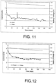
- a Duracell D size battery was stripped of its label and was directly inserted into a hole in a reinforced concrete slab of dimension 28 x 19 x 10.5 cm high.
- the bare metal casing of the battery was partially inserted into a 42mm diameter hole which was 38mm deep.
- the space between the battery and the inner surface of the hole was filled with ionically conductive gel comprised of lithium hydroxide, water and carboxymethylcellulose.
- the other terminal of the battery was connected to all of the steel bars in the concrete slab (four transverse and two longitudinal bars, each 2 cm in diameter) such that electrons flowed to the steel and the steel would be protected.
- An arrangement of this type when tested gave an initial current of around 3mA and maintained a current of over 1 mA for 145 days.
- the barrel itself is nickel coated steel which is not totally inert. Once there is a break in the nickel coating, corrosion of the steel will occur under the conditions that prevail at the surface of the metal.
- This may be overcome, according to the invention, by providing a coating which is a more effective inert (non-sacrificial) anode material such as MMO coated titanium, titanium sub-oxide, platinum, niobium or any other such material.
- the steel barrel may also be replaced with a barrel which is wholly made of more effective inert anode material as listed above.
- a two battery setup can be used.
- a sample as described above was prepared and a second battery was connected in series with the first battery.
- the casing of the first battery was directly inserted and used as the anode.
- This arrangement increased the driving voltage by a factor of two and surprisingly, the current to the steel reinforcement increased by a factor of three to four.
- Initial current was 9.5mA and a current of 3 to 4 mA was maintained for over 110 days.
- Further batteries (#3 and #4) were added in series to further increase the driving voltage.
- the increase in current to the steel reinforcement was roughly proportional to the increase in voltage.
- a D size battery was connected to various noble anode materials (according to the invention) and sacrificial anode materials (not according to the invention).
- These tested anode materials included MMO coated titanium, titanium sub-oxide tube, brass and zinc. Testing was completed on reinforced concrete blocks of the same dimensions as described above. The anodes were embedded in the concrete hole using ionically conductive gel. Batteries were electrically connected to the anode materials and to the reinforcing steel.
- the non-inert anodes, especially zinc, (unclaimed) delivered higher initial current than the inert anodes (claimed). Nonetheless a current of at least 1mA was achieved by all anodes.
- a stainless steel anode was used and was embedded in compacted sand dosed with a saturated solution of lithium hydroxide.
- the stainless steel anode was used to pass 30 to 50 mA current for a period of 14 days. Minimal corrosion was evident on the stainless steel anode surface after passing a total charge of 12.5 A-hrs of charge.
- zinc alkaline rechargeable AA size batteries were connected to mixed metal oxide (MMO) coated titanium anodes (invention) and zinc anodes (unclaimed) which were partially embedded in ionically conductive gel in a hole in a reinforced concrete block as described above.
- MMO mixed metal oxide
- the anode was connected to the terminal marked + and the steel was connected to the terminal marked - on an as received rechargeable battery. Current flowing to the steel was recorded. The battery was then disconnected and discharged. After discharging the battery the voltage of the battery was measured to confirm it was discharged. The battery was then recharged and reconnected. The current was recorded after the battery was recharged.
- the current produced when the battery was connected to the sacrificial anode (unclaimed) was greater than the current produced when the battery was connected to the inert MMO coated titanium anode (claimed). In both cases the current from the recharged battery exceeded the current from the original battery.
- the concept of using a battery or a rechargeable battery of the type described herein is an improvement over the conventional galvanic anode available in the market.
- a current output of more than 1mA can be maintained for many weeks without a significant drop in the battery voltage, indicating that cathodic protection can be maintained for several years.
- An inert anode such as MMO coated titanium, can be wrapped around, coated onto or otherwise electrically connected to the casing of the battery.
- the barrel of the battery may partially or fully comprise titanium and can be coated with MMO or titanium sub-oxide.
- a portion of sacrificial anode material such as zinc can be provided in combination with the required inert anode to provide additional current until the sacrificial portion is consumed (this embodiment is not claimed).
- the outer barrel of the battery can also be used as an impressed current anode in cases where an additional power supply is used to provide an initial charge to passivate the steel.
- Specially designed batteries can be modified to provide the desired parameters for this application such as low current, long life operation and to be more suitable for direct embedment into the concrete.
- Figures 11 and 12 are battery anode progress graphs of voltage and current vs time for the battery casing directly inserted in the hole in the concrete slab with Figure 12 showing a graph relating to a second battery connected in series to the first battery as described in the first set of examples.
- Figure 13 shows a graph of results for an assembly according to the invention as described herein with a battery and a MMO coated titanium anode showing current before (as received) and after recharging, based on the results set out hereinafter in Tables 1 and 2.
- Figure 14 shows tables and a graph of results for an assembly as described herein with a battery and a Zn anode showing current before (as received) and after recharging, based on the results set out hereinafter in Tables 3 and 4.
- TABLE 1 Ti MMO Area of Ti MMO exposed 6cm2 Battery Igo Green 1.5V Negative terminal of the battery is connected to 6 bars of steel, positive terminal of the battery connected to the MMO titanium ribbon anode MMO titanium ribbon is placed in a conductive gel in the concrete sample. Initial voltage of battery 1.571V for the Original Battery in as received condition.
- Zinc rod is placed in a conductive gel (lithium hydroxide, carboxymethylcellulose and water) in the concrete reservoir.
- Original Battery Initial voltage of battery 1.5694V (as received) Date Time Current mA Voltage V 22/03/2015 9:27 7.505 22/03/2015 9:29 6.737 22/03/2015 9:30 6.678 22/03/2015 9:31 6.642 22/03/2015 9:32 6.613 1.542 22/03/2015 9:33 6.58 22/03/2015 9:34 6.561 22/03/2015 9:38 6.518 22/152015 9:40 6.498 22/03/2015 9:47 6.38 22/15/01/2015 10:01 6.377 22/15/20/15 6.294 22/15/01/2015 10:26 6.273 22/152015 10:34 6.245 22/03/2015 11:29 6.191 22/03/2015 11:46 6.176 22/03/2015 11:48 6.174 1.523 22/152015 11:52 6.172
Landscapes
- Chemical & Material Sciences (AREA)
- Engineering & Computer Science (AREA)
- Materials Engineering (AREA)
- Mechanical Engineering (AREA)
- Metallurgy (AREA)
- Organic Chemistry (AREA)
- Prevention Of Electric Corrosion (AREA)
- Secondary Cells (AREA)
Claims (13)
- Verfahren zum kathodischen Schützen und/oder Passivieren eines Metallabschnitts in einem ionisch leitfähigen Material (41), umfassend:Bereitstellen einer Nicht-Opferanode (44) zur Kommunikation eines elektrischen Stroms an den Metallabschnitt (40) in dem ionisch leitfähigen Material, wobei die Nicht-Opferanode (44) aus einem Material ist, das gegenüber dem Metallabschnitt keine Opferfunktion übernimmt;Bereitstellen einer Speicherkomponente für elektrische Energie mit zwei Polen (42, 43) zum Kommunizieren von elektrischem Strom, der durch Abgabe der elektrischen Energie erzeugt wird;wobei die Speicherkomponente in einem Außengehäuse (12) mit einer Außenoberfläche enthalten ist;elektrisches Verbinden eines Pols (42) mit dem Metallabschnitt (40), elektrisches Verbinden des anderen Pols (43) mit der Nicht-Opferanode, und Platzieren der Nicht-Opferanode (44) in ionischem Kontakt mit dem ionisch leitfähigen Material (41), so dass der elektrische Strom von der Speicherkomponente durch die elektrische Verbindung (42A) zu dem Metallabschnitt (40) fließen kann, wodurch eine Gesamtmenge an elektrischer Energie reduziert wird, die in der Speicherkomponente enthalten ist;wobei die Nicht-Opferanode (44) auf der Außenoberfläche des Außengehäuses (12) definiert ist, so dass die Speicherkomponente als gemeinsame einzige Einheit mit der Nicht-Opferanode verbunden ist;und Platzieren der Nicht-Opferanode (44) in ionischer Kommunikation mit dem ionisch leitfähigen Material (41).
- Verfahren nach Anspruch 1, wobei der Metallabschnitt (40) Stahl ist und das ionisch leitfähige Material (41) Beton oder Mörtel ist.
- Verfahren nach Anspruch 1 oder 2, wobei die Nicht-Opferanode (44) und die Speicherkomponente beide mindestens teilweise in dem ionisch leitfähigen Material (41) enthalten sind.
- Verfahren nach einem der Ansprüche 1 bis 3, wobei die Speicherkomponente eine Zelle (49A) oder Batterie (49) von Zellen ist.
- Verfahren nach einem der Ansprüche 1 bis 3, wobei die Speicherkomponente ein Kondensator (120) ist.
- Verfahren nach einem der Ansprüche 1 bis 5, wobei die Nicht-Opferanode Edelstahl umfasst.
- Verfahren nach einem der Ansprüche 1 bis 6, wobei die Speicherkomponente in dem Außengehäuse nach einer Betriebsperiode durch eine Ersatzspeicherkomponente ersetzt wird, um zusätzliche elektrische Energie bereitzustellen.
- Verfahren nach einem der vorhergehenden Ansprüche, wobei elektrische Ersatzenergie in die Speicherkomponente eingebracht wird, während die Nicht-Opferanode (44) in Kontakt mit dem ionisch leitfähigen Material (41) ist.
- Verfahren nach Anspruch 8, wobei die elektrische Ersatzenergie durch Wiederaufladen der Speicherkomponente eingebracht wird.
- Baugruppe zum kathodischen Schützen und/oder Passivieren eines Stahlmetallabschnitts (40) in einem ionisch leitfähigen Material (41), umfassend:eine Nicht-Opferanode (44) aus einem Material, das gegenüber Stahl keine Opferfunktion übernimmt;eine Speicherkomponente für elektrische Energie mit zwei Polen (42, 43) zum Kommunizieren von elektrischem Strom, der durch Abgabe der elektrischen Energie erzeugt wird;wobei die Speicherkomponente in einem Außengehäuse (12) mit einer Außenoberfläche enthalten ist;eine Anordnung (42A) zum elektrischen Verbinden eines Pols (42) mit dem Metallabschnitt (40);eine Anordnung zum elektrischen Verbinden des anderen Pols (43) mit der Nicht-Opferanode;wobei die Baugruppe zum Platzieren der Nicht-Opferanode (44) in ionischen Kontakt mit dem ionisch leitfähigen Material (41) angeordnet ist, so dass Elektronen von der Speicherkomponente durch die elektrische Verbindungsanordnung (42A) zu dem Metallabschnitt (40) fließen können;wobei die Nicht-Opferanode (44) auf der Außenoberfläche des Außengehäuses (12) definiert ist, so dass die Speicherkomponente als einzige Einheit mit der Nicht-Opferanode (44) verbunden ist.
- Baugruppe nach Anspruch 10, wobei die Anode Edelstahl umfasst.
- Baugruppe nach Anspruch 10 oder 11, wobei die Speicherkomponente eine Zelle (49A) oder Batterie (49) von Zellen ist.
- Baugruppe nach einem der Ansprüche 10 bis 12, wobei die Speicherkomponente ein Kondensator (120) ist.
Priority Applications (1)
| Application Number | Priority Date | Filing Date | Title |
|---|---|---|---|
| EP25155900.1A EP4530374A2 (de) | 2015-11-03 | 2016-11-02 | Kathodischer korrosionsschutz |
Applications Claiming Priority (2)
| Application Number | Priority Date | Filing Date | Title |
|---|---|---|---|
| US201562250153P | 2015-11-03 | 2015-11-03 | |
| PCT/CA2016/051270 WO2017075699A1 (en) | 2015-11-03 | 2016-11-02 | Cathodic corrosion protection |
Related Child Applications (2)
| Application Number | Title | Priority Date | Filing Date |
|---|---|---|---|
| EP25155900.1A Division EP4530374A2 (de) | 2015-11-03 | 2016-11-02 | Kathodischer korrosionsschutz |
| EP25155900.1A Division-Into EP4530374A2 (de) | 2015-11-03 | 2016-11-02 | Kathodischer korrosionsschutz |
Publications (4)
| Publication Number | Publication Date |
|---|---|
| EP3371348A1 EP3371348A1 (de) | 2018-09-12 |
| EP3371348A4 EP3371348A4 (de) | 2019-07-03 |
| EP3371348B1 true EP3371348B1 (de) | 2025-03-19 |
| EP3371348C0 EP3371348C0 (de) | 2025-03-19 |
Family
ID=58637304
Family Applications (2)
| Application Number | Title | Priority Date | Filing Date |
|---|---|---|---|
| EP16861147.3A Active EP3371348B1 (de) | 2015-11-03 | 2016-11-02 | Kathodischer korrosionsschutz |
| EP25155900.1A Pending EP4530374A2 (de) | 2015-11-03 | 2016-11-02 | Kathodischer korrosionsschutz |
Family Applications After (1)
| Application Number | Title | Priority Date | Filing Date |
|---|---|---|---|
| EP25155900.1A Pending EP4530374A2 (de) | 2015-11-03 | 2016-11-02 | Kathodischer korrosionsschutz |
Country Status (6)
| Country | Link |
|---|---|
| US (3) | US10640877B2 (de) |
| EP (2) | EP3371348B1 (de) |
| JP (2) | JP2019501277A (de) |
| AU (1) | AU2016329042B1 (de) |
| SA (1) | SA518391382B1 (de) |
| WO (1) | WO2017075699A1 (de) |
Families Citing this family (13)
| Publication number | Priority date | Publication date | Assignee | Title |
|---|---|---|---|---|
| EP3371348B1 (de) * | 2015-11-03 | 2025-03-19 | Vector Corrosion Technologies Ltd | Kathodischer korrosionsschutz |
| CN110291656A (zh) * | 2016-12-15 | 2019-09-27 | 斯皮尔电力系统有限责任公司 | 具有集成式能量存储系统的建筑材料 |
| US10633746B2 (en) * | 2017-07-07 | 2020-04-28 | Vector Remediation Ltd. | Cathodic corrosion protection with current limiter |
| US11105001B2 (en) * | 2017-09-05 | 2021-08-31 | David William Whitmore | Cathodic corrosion protection with solar panel |
| CN111051572A (zh) | 2017-09-07 | 2020-04-21 | 开利公司 | 用于暖通空调制冷的腐蚀保护系统 |
| JP6836823B2 (ja) * | 2019-02-18 | 2021-03-03 | 有限会社フクイトレーディング | アース装置、アース方法 |
| WO2020198069A1 (en) * | 2019-03-22 | 2020-10-01 | Osmose Utilities Services, Inc. | Reactive corrosion protection systems and methods for making and using the same |
| JP7377096B2 (ja) * | 2019-12-24 | 2023-11-09 | 株式会社クボタ | 埋設金属管の防食装置及び埋設金属管の防食施工方法 |
| US12012659B2 (en) * | 2020-02-28 | 2024-06-18 | Valmont Industries, Inc. | System, method and apparatus for providing anodic corrosion protection for galvanized irrigation pipes |
| CA3234670A1 (en) * | 2020-04-27 | 2021-10-27 | Vector Remediation Ltd. | Cathodic corrosion protection with current limiter |
| IT202100008279A1 (it) * | 2021-04-01 | 2022-10-01 | Silvestro Scotto | Dispositivo per la protezione catodica di componenti metallici di imbarcazioni |
| KR20240116154A (ko) | 2023-01-20 | 2024-07-29 | 우병훈 | 건설구조물의 유지관리방법 |
| US12060802B1 (en) * | 2023-07-25 | 2024-08-13 | Ge Infrastructure Technology Llc | Systems and methods for preventing liberation and damage to airfoils in a gas turbine |
Family Cites Families (21)
| Publication number | Priority date | Publication date | Assignee | Title |
|---|---|---|---|---|
| US5649591A (en) * | 1995-01-20 | 1997-07-22 | Green; Michael Philip | Radiator cap with sacrificial anode |
| US5667649A (en) * | 1995-06-29 | 1997-09-16 | Bushman; James B. | Corrosion-resistant ferrous alloys for use as impressed current anodes |
| JPH0931675A (ja) * | 1995-07-14 | 1997-02-04 | Nakabootec:Kk | 複合増圧方式流電陽極による電気防食法およびそのための装置 |
| CA2444638C (en) | 2003-10-10 | 2008-11-25 | David W. Whitmore | Cathodic protection of steel within a covering material |
| JP4144881B2 (ja) * | 2004-04-15 | 2008-09-03 | 住友大阪セメント株式会社 | コンクリートへの電気防食電極の取り付け方法および電気防食電極の固定治具 |
| GB0409521D0 (en) * | 2004-04-29 | 2004-06-02 | Fosroc International Ltd | Sacrificial anode assembly |
| JP2006037118A (ja) * | 2004-07-22 | 2006-02-09 | Taiheiyo Cement Corp | 電気防食方法および電気防食装置 |
| US8999137B2 (en) * | 2004-10-20 | 2015-04-07 | Gareth Kevin Glass | Sacrificial anode and treatment of concrete |
| GB0505353D0 (en) * | 2005-03-16 | 2005-04-20 | Chem Technologies Ltd E | Treatment process for concrete |
| US7169288B2 (en) * | 2004-11-03 | 2007-01-30 | Adc Dsl Systems, Inc. | Methods and systems of cathodic protection for metallic enclosures |
| CA2488298C (en) | 2004-11-23 | 2008-10-14 | Bourgault Industries Ltd. | Bale processor with grain mixing attachment |
| JP2006265695A (ja) * | 2005-03-25 | 2006-10-05 | Osaka Gas Co Ltd | 電気防食用電極体及びその設置方法 |
| EP2348141B1 (de) * | 2010-01-22 | 2017-10-18 | Oticon A/S | Verwendung einer Opferanode zum Schutz vor Korrosion eines tragbaren Gerätes, z. B. eines Hörgerätes |
| JP5706753B2 (ja) * | 2011-05-12 | 2015-04-22 | 三井住友建設株式会社 | 橋桁端部の電気防食方法 |
| WO2013152398A1 (en) * | 2012-04-11 | 2013-10-17 | Anode Engineering Pty Ltd | Cathodic protection system |
| JP6273654B2 (ja) * | 2012-07-19 | 2018-02-07 | ベクター コロージョン テクノロジーズ エルティーディー. | 犠牲陽極を使用する腐食防止 |
| US8968549B2 (en) | 2012-07-19 | 2015-03-03 | Vector Corrosion Technologies Ltd. | Two stage cathodic protection system using impressed current and galvanic action |
| US8961746B2 (en) | 2012-07-19 | 2015-02-24 | Vector Corrosion Technologies Ltd. | Charging a sacrificial anode with ions of the sacrificial material |
| US20150284860A1 (en) * | 2012-10-18 | 2015-10-08 | Gareth Glass | Protection of steel reinforced concrete elements |
| US9637827B2 (en) * | 2013-10-01 | 2017-05-02 | William Marsh Rice University | Methods of preventing corrosion of surfaces by application of energy storage-conversion devices |
| EP3371348B1 (de) * | 2015-11-03 | 2025-03-19 | Vector Corrosion Technologies Ltd | Kathodischer korrosionsschutz |
-
2016
- 2016-11-02 EP EP16861147.3A patent/EP3371348B1/de active Active
- 2016-11-02 JP JP2018514304A patent/JP2019501277A/ja active Pending
- 2016-11-02 AU AU2016329042A patent/AU2016329042B1/en active Active
- 2016-11-02 EP EP25155900.1A patent/EP4530374A2/de active Pending
- 2016-11-02 US US15/341,532 patent/US10640877B2/en active Active
- 2016-11-02 WO PCT/CA2016/051270 patent/WO2017075699A1/en not_active Ceased
-
2018
- 2018-04-18 SA SA518391382A patent/SA518391382B1/ar unknown
-
2019
- 2019-09-04 JP JP2019161521A patent/JP2020002468A/ja active Pending
- 2019-11-26 US US16/696,382 patent/US20200095691A1/en not_active Abandoned
-
2024
- 2024-01-12 US US18/411,316 patent/US20240209515A1/en active Pending
Also Published As
| Publication number | Publication date |
|---|---|
| US20240209515A1 (en) | 2024-06-27 |
| US20200095691A1 (en) | 2020-03-26 |
| JP2020002468A (ja) | 2020-01-09 |
| EP4530374A2 (de) | 2025-04-02 |
| WO2017075699A1 (en) | 2017-05-11 |
| US20170121828A1 (en) | 2017-05-04 |
| EP3371348A1 (de) | 2018-09-12 |
| JP2019501277A (ja) | 2019-01-17 |
| EP3371348C0 (de) | 2025-03-19 |
| SA518391382B1 (ar) | 2022-06-15 |
| US10640877B2 (en) | 2020-05-05 |
| AU2016329042B1 (en) | 2017-05-25 |
| EP3371348A4 (de) | 2019-07-03 |
Similar Documents
| Publication | Publication Date | Title |
|---|---|---|
| US20240209515A1 (en) | Cathodic corrosion protection | |
| CA3062559C (en) | Cathodic corrosion protection with current limiter | |
| CA3019322C (en) | Cathodic corrosion protection system with rebar mounting assembly | |
| JP6590902B2 (ja) | 犠牲陽極を使用する腐食防止 | |
| CA2961848C (en) | Cathodic corrosion protection | |
| US11384438B2 (en) | Cathodic corrosion protection system with rebar mounting assembly | |
| CA3060923C (en) | Cathodic corrosiion protection system with rebar mounting assembly | |
| AU2019275613B2 (en) | Cathodic corrosion protection system with rebar mounting assesmbly | |
| AU2021202361B2 (en) | Cathodic corrosion protection with current limiter |
Legal Events
| Date | Code | Title | Description |
|---|---|---|---|
| STAA | Information on the status of an ep patent application or granted ep patent |
Free format text: STATUS: THE INTERNATIONAL PUBLICATION HAS BEEN MADE |
|
| PUAI | Public reference made under article 153(3) epc to a published international application that has entered the european phase |
Free format text: ORIGINAL CODE: 0009012 |
|
| STAA | Information on the status of an ep patent application or granted ep patent |
Free format text: STATUS: REQUEST FOR EXAMINATION WAS MADE |
|
| 17P | Request for examination filed |
Effective date: 20180529 |
|
| AK | Designated contracting states |
Kind code of ref document: A1 Designated state(s): AL AT BE BG CH CY CZ DE DK EE ES FI FR GB GR HR HU IE IS IT LI LT LU LV MC MK MT NL NO PL PT RO RS SE SI SK SM TR |
|
| AX | Request for extension of the european patent |
Extension state: BA ME |
|
| DAV | Request for validation of the european patent (deleted) | ||
| DAX | Request for extension of the european patent (deleted) | ||
| A4 | Supplementary search report drawn up and despatched |
Effective date: 20190603 |
|
| RIC1 | Information provided on ipc code assigned before grant |
Ipc: C23F 13/06 20060101ALI20190527BHEP Ipc: C23F 13/20 20060101AFI20190527BHEP |
|
| STAA | Information on the status of an ep patent application or granted ep patent |
Free format text: STATUS: EXAMINATION IS IN PROGRESS |
|
| 17Q | First examination report despatched |
Effective date: 20210510 |
|
| GRAP | Despatch of communication of intention to grant a patent |
Free format text: ORIGINAL CODE: EPIDOSNIGR1 |
|
| STAA | Information on the status of an ep patent application or granted ep patent |
Free format text: STATUS: GRANT OF PATENT IS INTENDED |
|
| INTG | Intention to grant announced |
Effective date: 20241017 |
|
| RIN1 | Information on inventor provided before grant (corrected) |
Inventor name: WHITMORE, DAVID Inventor name: RATHOD, TEJAL Inventor name: SERGI, GEORGE Inventor name: SIMPSON, DAVID |
|
| GRAS | Grant fee paid |
Free format text: ORIGINAL CODE: EPIDOSNIGR3 |
|
| GRAA | (expected) grant |
Free format text: ORIGINAL CODE: 0009210 |
|
| STAA | Information on the status of an ep patent application or granted ep patent |
Free format text: STATUS: THE PATENT HAS BEEN GRANTED |
|
| AK | Designated contracting states |
Kind code of ref document: B1 Designated state(s): AL AT BE BG CH CY CZ DE DK EE ES FI FR GB GR HR HU IE IS IT LI LT LU LV MC MK MT NL NO PL PT RO RS SE SI SK SM TR |
|
| REG | Reference to a national code |
Ref country code: GB Ref legal event code: FG4D |
|
| REG | Reference to a national code |
Ref country code: CH Ref legal event code: EP |
|
| REG | Reference to a national code |
Ref country code: IE Ref legal event code: FG4D |
|
| REG | Reference to a national code |
Ref country code: DE Ref legal event code: R096 Ref document number: 602016091634 Country of ref document: DE |
|
| U01 | Request for unitary effect filed |
Effective date: 20250410 |
|
| U07 | Unitary effect registered |
Designated state(s): AT BE BG DE DK EE FI FR IT LT LU LV MT NL PT RO SE SI Effective date: 20250416 |
|
| PG25 | Lapsed in a contracting state [announced via postgrant information from national office to epo] |
Ref country code: RS Free format text: LAPSE BECAUSE OF FAILURE TO SUBMIT A TRANSLATION OF THE DESCRIPTION OR TO PAY THE FEE WITHIN THE PRESCRIBED TIME-LIMIT Effective date: 20250619 |
|
| PG25 | Lapsed in a contracting state [announced via postgrant information from national office to epo] |
Ref country code: NO Free format text: LAPSE BECAUSE OF FAILURE TO SUBMIT A TRANSLATION OF THE DESCRIPTION OR TO PAY THE FEE WITHIN THE PRESCRIBED TIME-LIMIT Effective date: 20250619 |
|
| PG25 | Lapsed in a contracting state [announced via postgrant information from national office to epo] |
Ref country code: HR Free format text: LAPSE BECAUSE OF FAILURE TO SUBMIT A TRANSLATION OF THE DESCRIPTION OR TO PAY THE FEE WITHIN THE PRESCRIBED TIME-LIMIT Effective date: 20250319 |
|
| PG25 | Lapsed in a contracting state [announced via postgrant information from national office to epo] |
Ref country code: GR Free format text: LAPSE BECAUSE OF FAILURE TO SUBMIT A TRANSLATION OF THE DESCRIPTION OR TO PAY THE FEE WITHIN THE PRESCRIBED TIME-LIMIT Effective date: 20250620 |
|
| PG25 | Lapsed in a contracting state [announced via postgrant information from national office to epo] |
Ref country code: SM Free format text: LAPSE BECAUSE OF FAILURE TO SUBMIT A TRANSLATION OF THE DESCRIPTION OR TO PAY THE FEE WITHIN THE PRESCRIBED TIME-LIMIT Effective date: 20250319 |
|
| PG25 | Lapsed in a contracting state [announced via postgrant information from national office to epo] |
Ref country code: ES Free format text: LAPSE BECAUSE OF FAILURE TO SUBMIT A TRANSLATION OF THE DESCRIPTION OR TO PAY THE FEE WITHIN THE PRESCRIBED TIME-LIMIT Effective date: 20250319 |
|
| PG25 | Lapsed in a contracting state [announced via postgrant information from national office to epo] |
Ref country code: PL Free format text: LAPSE BECAUSE OF FAILURE TO SUBMIT A TRANSLATION OF THE DESCRIPTION OR TO PAY THE FEE WITHIN THE PRESCRIBED TIME-LIMIT Effective date: 20250319 |
|
| PG25 | Lapsed in a contracting state [announced via postgrant information from national office to epo] |
Ref country code: CZ Free format text: LAPSE BECAUSE OF FAILURE TO SUBMIT A TRANSLATION OF THE DESCRIPTION OR TO PAY THE FEE WITHIN THE PRESCRIBED TIME-LIMIT Effective date: 20250319 |
|
| PG25 | Lapsed in a contracting state [announced via postgrant information from national office to epo] |
Ref country code: SK Free format text: LAPSE BECAUSE OF FAILURE TO SUBMIT A TRANSLATION OF THE DESCRIPTION OR TO PAY THE FEE WITHIN THE PRESCRIBED TIME-LIMIT Effective date: 20250319 |
|
| PG25 | Lapsed in a contracting state [announced via postgrant information from national office to epo] |
Ref country code: IS Free format text: LAPSE BECAUSE OF FAILURE TO SUBMIT A TRANSLATION OF THE DESCRIPTION OR TO PAY THE FEE WITHIN THE PRESCRIBED TIME-LIMIT Effective date: 20250719 |
|
| U20 | Renewal fee for the european patent with unitary effect paid |
Year of fee payment: 10 Effective date: 20251127 |
|
| PGFP | Annual fee paid to national office [announced via postgrant information from national office to epo] |
Ref country code: GB Payment date: 20251121 Year of fee payment: 10 |
|
| PLBE | No opposition filed within time limit |
Free format text: ORIGINAL CODE: 0009261 |
|
| STAA | Information on the status of an ep patent application or granted ep patent |
Free format text: STATUS: NO OPPOSITION FILED WITHIN TIME LIMIT |
|
| REG | Reference to a national code |
Ref country code: CH Ref legal event code: L10 Free format text: ST27 STATUS EVENT CODE: U-0-0-L10-L00 (AS PROVIDED BY THE NATIONAL OFFICE) Effective date: 20260128 |
|
| 26N | No opposition filed |
Effective date: 20251222 |